EP3674205B1 - Vorflügel mit optimierter struktur - Google Patents
Vorflügel mit optimierter struktur Download PDFInfo
- Publication number
- EP3674205B1 EP3674205B1 EP19202335.6A EP19202335A EP3674205B1 EP 3674205 B1 EP3674205 B1 EP 3674205B1 EP 19202335 A EP19202335 A EP 19202335A EP 3674205 B1 EP3674205 B1 EP 3674205B1
- Authority
- EP
- European Patent Office
- Prior art keywords
- skin
- spar
- leading
- slat
- bosses
- Prior art date
- Legal status (The legal status is an assumption and is not a legal conclusion. Google has not performed a legal analysis and makes no representation as to the accuracy of the status listed.)
- Active
Links
Images
Classifications
-
- B—PERFORMING OPERATIONS; TRANSPORTING
- B64—AIRCRAFT; AVIATION; COSMONAUTICS
- B64C—AEROPLANES; HELICOPTERS
- B64C3/00—Wings
- B64C3/26—Construction, shape, or attachment of separate skins, e.g. panels
-
- B—PERFORMING OPERATIONS; TRANSPORTING
- B64—AIRCRAFT; AVIATION; COSMONAUTICS
- B64C—AEROPLANES; HELICOPTERS
- B64C3/00—Wings
- B64C3/28—Leading or trailing edges attached to primary structures, e.g. forming fixed slots
-
- B—PERFORMING OPERATIONS; TRANSPORTING
- B64—AIRCRAFT; AVIATION; COSMONAUTICS
- B64C—AEROPLANES; HELICOPTERS
- B64C3/00—Wings
- B64C3/18—Spars; Ribs; Stringers
- B64C3/185—Spars
-
- B—PERFORMING OPERATIONS; TRANSPORTING
- B64—AIRCRAFT; AVIATION; COSMONAUTICS
- B64C—AEROPLANES; HELICOPTERS
- B64C9/00—Adjustable control surfaces or members, e.g. rudders
- B64C9/14—Adjustable control surfaces or members, e.g. rudders forming slots
- B64C9/22—Adjustable control surfaces or members, e.g. rudders forming slots at the front of the wing
- B64C9/24—Adjustable control surfaces or members, e.g. rudders forming slots at the front of the wing by single flap
-
- B—PERFORMING OPERATIONS; TRANSPORTING
- B29—WORKING OF PLASTICS; WORKING OF SUBSTANCES IN A PLASTIC STATE IN GENERAL
- B29L—INDEXING SCHEME ASSOCIATED WITH SUBCLASS B29C, RELATING TO PARTICULAR ARTICLES
- B29L2031/00—Other particular articles
- B29L2031/30—Vehicles, e.g. ships or aircraft, or body parts thereof
- B29L2031/3076—Aircrafts
- B29L2031/3082—Fuselages
-
- B—PERFORMING OPERATIONS; TRANSPORTING
- B29—WORKING OF PLASTICS; WORKING OF SUBSTANCES IN A PLASTIC STATE IN GENERAL
- B29L—INDEXING SCHEME ASSOCIATED WITH SUBCLASS B29C, RELATING TO PARTICULAR ARTICLES
- B29L2031/00—Other particular articles
- B29L2031/30—Vehicles, e.g. ships or aircraft, or body parts thereof
- B29L2031/3076—Aircrafts
- B29L2031/3085—Wings
-
- B—PERFORMING OPERATIONS; TRANSPORTING
- B32—LAYERED PRODUCTS
- B32B—LAYERED PRODUCTS, i.e. PRODUCTS BUILT-UP OF STRATA OF FLAT OR NON-FLAT, e.g. CELLULAR OR HONEYCOMB, FORM
- B32B2605/00—Vehicles
- B32B2605/18—Aircraft
-
- B—PERFORMING OPERATIONS; TRANSPORTING
- B64—AIRCRAFT; AVIATION; COSMONAUTICS
- B64C—AEROPLANES; HELICOPTERS
- B64C1/00—Fuselages; Constructional features common to fuselages, wings, stabilising surfaces or the like
- B64C1/06—Frames; Stringers; Longerons ; Fuselage sections
- B64C1/12—Construction or attachment of skin panels
-
- B—PERFORMING OPERATIONS; TRANSPORTING
- B64—AIRCRAFT; AVIATION; COSMONAUTICS
- B64C—AEROPLANES; HELICOPTERS
- B64C1/00—Fuselages; Constructional features common to fuselages, wings, stabilising surfaces or the like
- B64C2001/0054—Fuselage structures substantially made from particular materials
- B64C2001/0072—Fuselage structures substantially made from particular materials from composite materials
-
- B—PERFORMING OPERATIONS; TRANSPORTING
- B64—AIRCRAFT; AVIATION; COSMONAUTICS
- B64C—AEROPLANES; HELICOPTERS
- B64C3/00—Wings
- B64C3/18—Spars; Ribs; Stringers
- B64C3/187—Ribs
Definitions
- the invention relates to an aircraft wing leading edge slat such as a leading edge tilting slat, or "slat", the structure of which of the slat is optimized.
- slat leading edge tilting slat
- the invention relates to a stiffening structure of such a leading edge nose.
- Wing leading edge slats are present on an aircraft both on the horizontal planes, wings and horizontal fin planes, and on the vertical planes such as on the fin.
- the slats present on an aircraft wing are tilting leading edges which make it possible, by their controlled movement, to modify the aerodynamic flow around the wing and to modify its lift at a given speed.
- a civil transport aircraft generally comprises 3 to 5 slats distributed on the leading edges of the wings, from the root of the wing to the tip, which follow the evolution of the section of the wing between its two ends. .
- a slat is thus a bearing surface of the wing which can recover, at a given wingspan position, up to 30% of the total lift of the wing section.
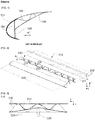
- the figure 1 schematically represents the section, in the xz plane, of a slat according to the prior art.
- the axis system shown is that of the airplane, the fuselage extends parallel to the x axis and the airfoil essentially along the y axis.
- Such a slat comprises an extrados skin (110) extending from the leading edge (beak) to the trailing edge.
- This is, according to some embodiments, made up of several parts.
- a spar (120) is assembled to the extrados skin (110) to which ribs are linked.
- An inner skin (130) is linked to the upper surface skin (110) by means of a stiffening system (140) such as stringers, ribs, or even a honeycomb structure according to the method of production.
- a stiffening system such as stringers, ribs, or even a honeycomb structure according to the method of production.
- the slat is linked to the wing by means of one or more interface fittings (not shown) connected by means of arms or maneuver rails to mechanical or hydraulic actuator means to achieve the controlled relative displacement. of the slat in relation to the wing.
- the schematically represented structure figure 1 corresponds to an example of a metal construction, but the composite constructions of the prior art are similar.
- a slat In terms of rigidity, a slat must be rigid enough to withstand aerodynamic forces.
- the aerodynamic forces undergone by the slat are transferred to the airfoil via the interface fittings and the rails or maneuvering arms which must be dimensioned accordingly according to the number of fittings.
- connection of the slat with the wing comprises more than two fittings, which is frequent, the assembly is hyperstatic.
- This hyperstatism combined with the differences in deformation is responsible for half of the forces to which said fittings and the slat are subjected, the rest coming from the aerodynamic loading.
- leading edges of the airfoil elements are exposed to impacts, in particular to impacts with birds.
- the skin forms the leading edge nose, is linked to the spar and stiffened by straight ribs (150) perpendicular to the spar.
- straight ribs 150
- up to 18 ribs are thus distributed along the y axis between the spar and the skin forming the leading edge, thus forming a multiple box structure.
- each of these ribs (150) weighs approximately 200 grams, ie a total weight attributable to this stiffening of the order of 3.6 kg.
- the majority component of the speed of impact of an object or a bird on the leading edge is parallel to the x axis, and corresponds to the speed of movement of the aircraft.
- Multiplying the ribs in addition to increasing the mass, increases the rigidity of the slat and reduces its ability to follow the deformations of the wing, increasing the interface forces linked to the differences in deformation between the wing and the slat.
- the invention aims to solve the drawbacks of the prior art and relates to this end a leading edge nose of a wing element of an aircraft, said aircraft defining a reference comprising a main fuselage axis x and a y span axis, the wing element providing lift along a z axis, comprising a skin forming the leading edge nose, a spar linked to said skin and a stiffening structure linked on the leading edge side to said spar and to the skin, in which the stiffening structure consists of a formed sheet comprising a plurality of bosses distributed along the length of the leading edge, said bosses extending between the spar and the internal face of the skin and in which the bosses form domes comprising a zone in contact with the skin and tangent to the latter, the hollows between the bosses being in contact with the spar and tangent to the latter.
- this stiffening structure makes it possible to distribute the impact energy over a larger area, limiting the risks of degradation of the spar, but
- the invention is implemented according to the embodiments and the variants set out below, which are to be considered individually or according to any technically operative combination.
- said spout is a movable leading edge or slat spout.
- the stiffening provided by the structure which is the subject of the invention is less than the same impact absorption capacity, thus favoring the monitoring of the deformations of the wing and limiting the impacts. strain incompatibility constraints.
- the sides of the bosses form an angle of less than 90 ° with respect to the surface of the spar and to the surface of the skin.
- the inclination of the sides of the bosses promotes the absorption of impact energy both by the stiffening plate and by the skin forming the leading edge nose.
- the stiffening structure consists of a composite material with continuous fibers in a thermoplastic matrix. This embodiment makes it possible to lighten the structure, by taking advantage of the better distribution of impact energy to allow a construction in composite material.
- the skin forming the nose and the spar are also made of a composite material with continuous fibers and a polymer matrix, and the stiffening structure is linked to the spar and to the skin by welding.
- This embodiment allows a saving in mass facilitates the assemblies.
- the pitch of the bosses is variable over the length of the leading edge nose.
- Figure 2 corresponding for example to the leading edge of a slat, the structure of a leading edge according to the invention, comprises a spar (210) of substantially U-shaped section, and a skin (220), in partial representation in this figure, forming the leading edge.
- the skin is extended as a single piece or in several assembled parts, on the upper surface side and the lower surface side.
- the spar (210) comprises a web (211) extending in the yz plane according to this embodiment and flanges (212) on either side of the web.
- the spar (210) and the skin (220) are linked by the flanges (212) of the spar on the upper and lower surfaces by riveting or by welding depending on the embodiments.
- the spar (210) and the skin (220) are made of a metallic material, for example an aluminum alloy or are made of a composite with continuous reinforcement in a thermosetting or thermoplastic polymer matrix.
- a stiffening structure (230) extends between the skin (220) and the spar (210) it is fixed on the one hand to the web (211) of the spar and on the other hand to the inner face of the skin .
- the stiffening structure (230) is a sheet comprising a plurality of bosses (231), distributed along the length, here the y axis, of the leading edge.
- Each boss (231) forms a dome comprising, on the skin side, a zone (232) tangent to the inner surface of the skin, and in the hollow between two bumps, a zone (233) tangent to the surface of the core (211) of the spar.
- None of the sides of the domes constituting the bosses (231) is parallel to the normal to the web of the spar, so that no surface of said dome is parallel to the main component of the speed vector, directed essentially according to the x axis, of an object impacting the leading edge.
- the stiffening structure comprises 9 domes (231) distributed at a regular pitch along the y axis. It advantageously replaces 9 straight ribs between the spar and the leading edge skin.
- the pitch of the bosses is variable and preferably increases along the y axis as it moves away from the root of the element. airfoil so as to adapt the stiffening to the rigidity of said airfoil element.
- the stiffening structure consists of a sheet formed from an aluminum alloy. Such a shape is obtained by hydroforming, superplastic forming or even by incremental forming.
- the sheet has a thickness of 1 mm and weighs approximately 500 grams, thus representing a gain of 1.3 kg compared to a solution of the prior art using 9 straight ribs of 200 grams each.
- the stiffening structure (230) consists of a composite material comprising a continuous reinforcement, for example in the form of carbon fibers, in a thermoplastic polymer matrix, for example of polyetheretherketone (PEEK).
- a continuous reinforcement for example in the form of carbon fibers
- a thermoplastic polymer matrix for example of polyetheretherketone (PEEK).
- thermoplastic polymer matrix provides superior impact resistance compared to a thermosetting matrix.
- the stiffening structure (230) is advantageously assembled to the spar (210) and to the skin (220) by welding, these also being of composite structure.
- Welding is carried out by ultrasound or by bringing the assembly to be assembled to an appropriate temperature in a tool. If one of the skin or of the spar consists of a composite with a thermosetting matrix, a thermoplastic film capable of bonding with the polymer constituting the matrix of this element is deposited beforehand on the surfaces corresponding to the assembly zones.
- this film is deposited by an additive manufacturing process according to a method as described in the document EP 3,242,790 .
- the pitch of the bosses as well as the angles of their flanks are chosen so as to facilitate the passage of a fiber placement head for their production.
- leading edge structure allows both: a gain in weight, better impact resistance and stiffening better preserving the deformation compatibility between the leading edge and the wing element when this leading edge is mobile.
- the structure that is the subject of the invention opens up the possibility of producing a leading edge according to a composite construction capable of meeting the impact resistance requirements.
Landscapes
- Engineering & Computer Science (AREA)
- Aviation & Aerospace Engineering (AREA)
- Mechanical Engineering (AREA)
- Laminated Bodies (AREA)
Claims (6)
- Vorderkantenleiste eines Flügelelements eines Flugzeugs, wobei das Flugzeug eine Markierung definiert, umfassend eine Rumpf-Hauptachse x und eine Spannweitenachse y, wobei das Flügelelement ein Tragfähigkeit gemäß eine Achse z aufweist, umfassend eine die Vorderkantenleiste formende Schale (220), einen mit der Schale verbundenen Längsträger (210) und eine an der Seite der Vorderkantenleiste mit dem Längsträger und der Schale verbundene Versteifungsstruktur (230), wobei die Versteifungsstruktur (230) aus einem geformten Blech besteht, aus einer Vielzahl von Buckeln (231) bestehend, verteilt gemäß der Länge der Vorderkante, wobei sich die Buckel zwischen dem Längsträger und der Innenseite der Schale erstrecken, dadurch gekennzeichnet, dass die Buckel (231) Kuppeln formen, umfassend einen Bereich (232) in Kontakt mit der Schale und diese tangierend, wobei die Hohlräume (233) zwischen den Buckeln in Kontakt mit dem Längsträger (210) sind und diesen tangieren.
- Vorderkantenleiste nach Anspruch 1, in welcher die Leiste eine mobile Vorderkantenleiste oder -lamelle ist.
- Vorderkantenleiste nach Anspruch 1, in welcher die Flanken der Kuppeln (231) im Verhältnis zu der Oberfläche des Längsträgers und der Oberfläche der Schale, mit denen sie in Kontakt sind, einen Winkel von weniger als 90° bilden.
- Vorderkantenleiste nach Anspruch 1, in welcher die Versteifungsstruktur (230) aus einem Verbundmaterial aus durchgehenden Fasern in einer thermoplastischen Matrix besteht.
- Vorderkantenleiste nach Anspruch 4, in welcher die die Leiste formende Schale (220) und der Längsträger (210) aus einem Verbundmaterial aus durchgehenden Fasern in einer Polymermatrix bestehen, und in welcher die Versteifungsstruktur (230) mit dem Längsträger und der Schale durch Verschweißung verbunden ist.
- Vorderkantenleiste nach Anspruch 1, in welcher der Schritt der Verteilung der Kuppeln (231) entlang der Länge der Vorderkantenleiste variabel ist.
Applications Claiming Priority (1)
| Application Number | Priority Date | Filing Date | Title |
|---|---|---|---|
| FR1874356A FR3091263A1 (fr) | 2018-12-28 | 2018-12-28 | Bec de bord d’attaque à structure optimisée |
Publications (2)
| Publication Number | Publication Date |
|---|---|
| EP3674205A1 EP3674205A1 (de) | 2020-07-01 |
| EP3674205B1 true EP3674205B1 (de) | 2021-05-05 |
Family
ID=66690612
Family Applications (1)
| Application Number | Title | Priority Date | Filing Date |
|---|---|---|---|
| EP19202335.6A Active EP3674205B1 (de) | 2018-12-28 | 2019-10-09 | Vorflügel mit optimierter struktur |
Country Status (3)
| Country | Link |
|---|---|
| US (1) | US11260956B2 (de) |
| EP (1) | EP3674205B1 (de) |
| FR (1) | FR3091263A1 (de) |
Families Citing this family (2)
| Publication number | Priority date | Publication date | Assignee | Title |
|---|---|---|---|---|
| EP4303122A1 (de) * | 2022-07-07 | 2024-01-10 | Airbus Operations GmbH | Flügel für ein flugzeug |
| WO2025229479A1 (en) * | 2024-04-29 | 2025-11-06 | Leonardo S.P.A. | Leading edge system for an aircraft, provided with an assembly for absorbing impacts |
Family Cites Families (15)
| Publication number | Priority date | Publication date | Assignee | Title |
|---|---|---|---|---|
| US5366177A (en) * | 1992-10-05 | 1994-11-22 | Rockwell International Corporation | Laminar flow control apparatus for aerodynamic surfaces |
| JP3647612B2 (ja) * | 1997-07-24 | 2005-05-18 | 富士重工業株式会社 | 航空機の前縁構造及びその製造方法 |
| JP3973474B2 (ja) * | 2002-04-05 | 2007-09-12 | 日本飛行機株式会社 | 航空機翼前縁部の製造方法 |
| US20040237763A1 (en) * | 2003-06-02 | 2004-12-02 | Ashok Bhatnagar | Corrugated ballistic armor |
| DE602005002144D1 (de) * | 2004-05-13 | 2007-10-04 | Airbus Gmbh | Flugzeugbauteil, insbesondere flügel |
| DE102004029485B4 (de) * | 2004-06-18 | 2007-05-31 | Eads Deutschland Gmbh | Impuls-absorbierendes Struktur-Bauteil |
| DE102007038634B3 (de) * | 2007-08-16 | 2008-07-31 | Eads Deutschland Gmbh | Impuls-absorbierendes Struktur-Bauteil |
| GB0720387D0 (en) * | 2007-10-18 | 2007-11-28 | Airbus Uk Ltd | Panel with impact protection membrane |
| GB0900494D0 (en) * | 2009-01-14 | 2009-02-11 | Airbus Uk Ltd | Aerofoil Structure |
| US10556670B2 (en) * | 2010-08-15 | 2020-02-11 | The Boeing Company | Laminar flow panel |
| DE102011101303A1 (de) * | 2011-05-12 | 2012-11-15 | Eads Deutschland Gmbh | Schlagschutzplatte für Fahrzeuge, insbesondere Luftfahrzeuge |
| US9708030B1 (en) * | 2011-12-08 | 2017-07-18 | The Boeing Company | Impact-energy tolerant method and structures |
| JP6238168B2 (ja) * | 2014-02-04 | 2017-11-29 | 三菱重工業株式会社 | 複合材構造 |
| FR3031471A1 (fr) * | 2015-01-09 | 2016-07-15 | Daher Aerospace | Procede pour la fabrication d’un piece composite complexe, notamment a matrice thermoplastique et piece obtenue par un tel procede |
| GB201522327D0 (en) * | 2015-12-17 | 2016-02-03 | Airbus Operations Ltd | Wing structure |
-
2018
- 2018-12-28 FR FR1874356A patent/FR3091263A1/fr not_active Withdrawn
-
2019
- 2019-10-09 EP EP19202335.6A patent/EP3674205B1/de active Active
- 2019-12-26 US US16/727,189 patent/US11260956B2/en active Active
Also Published As
| Publication number | Publication date |
|---|---|
| FR3091263A1 (fr) | 2020-07-03 |
| US11260956B2 (en) | 2022-03-01 |
| EP3674205A1 (de) | 2020-07-01 |
| US20200207458A1 (en) | 2020-07-02 |
Similar Documents
| Publication | Publication Date | Title |
|---|---|---|
| BE1015867A3 (fr) | Ensemble de bord d'attaque d'un element de voilure d'aeronef et element de voilure equipee d'au moins un tel ensemble. | |
| EP2653377B1 (de) | Aerodynamische Tragfläche eines Luftfahrzeugs, und mit einer solchen aerodynamischen Tragfläche ausgestattetes Luftfahrzeug | |
| EP2242683B1 (de) | Monolothische, selbstversteifende und schwenkbare verbundplatte, insbesondere für ein mobiles flugzeugbauteil | |
| EP2363342B1 (de) | Blatt mit adaptiver Verdrehung und Rotor mit einem solchen Blatt | |
| WO2022018357A1 (fr) | Turbomachine d'aeronef comportant des aubes d'helice a calage variable | |
| WO2022208002A1 (fr) | Aube comprenant une structure en matériau composite et procédé de fabrication associé | |
| FR2993942A1 (fr) | Aube composite de turbomachine a renfort structurel | |
| EP3674205B1 (de) | Vorflügel mit optimierter struktur | |
| EP3521173B1 (de) | Einheit für luftfahrzeug, die eine primärstruktur einer aufhängesäule umfasst, die an einem fahrwerkskasten mithilfe einer verschraubten verbindung befestigt ist | |
| EP3356650A1 (de) | Schaufel mit einer eintrittskantenabschirmung und verfahren zur herstellung dieser schaufel | |
| EP2818408B1 (de) | Rotorblatt mit verminderter Torsionssteifigkeit, und mit diesem Blatt ausgestatteter Rotor | |
| CA2951757C (fr) | Procede d'assemblage d'un ensemble de pieces composites et ensemble obtenu par un tel procede | |
| EP2692631B1 (de) | Spant eines Luftfahrzeugs mit verjüngtem Abschnitt | |
| EP3670331B1 (de) | Tragfläche mit einem beweglichen element | |
| EP1961658B1 (de) | Rotorblatt versehen mit einem Radialabschnitt und mindestens einem gepfeilten Abschnitt vorher und/oder hinterher | |
| FR3069185A1 (fr) | Profil aerodynamique a noyau creux oblong arrondi en materiau composite renforce par un textile a fibres unidirectionnelles | |
| EP3287363B1 (de) | Tragflächenerweiterung für einen flügel eines luftfahrzeugs | |
| EP1768898B1 (de) | Bewegliche vorderkantenklappe für einen hauptflügel der tragflächen eines flugzeugs | |
| EP4061702B1 (de) | Aerodynamisches element mit zwei aerodynamischen teilen, die eine ansteigende profilverbindung bilden | |
| FR3085414A1 (fr) | Aube de turbomachine comportant une liaison au renfort structurel a inserts et evidements | |
| WO2025062088A1 (fr) | Turbomachine d'aeronef comportant des aubes d'helice a calage variable |
Legal Events
| Date | Code | Title | Description |
|---|---|---|---|
| PUAI | Public reference made under article 153(3) epc to a published international application that has entered the european phase |
Free format text: ORIGINAL CODE: 0009012 |
|
| STAA | Information on the status of an ep patent application or granted ep patent |
Free format text: STATUS: REQUEST FOR EXAMINATION WAS MADE |
|
| 17P | Request for examination filed |
Effective date: 20191009 |
|
| AK | Designated contracting states |
Kind code of ref document: A1 Designated state(s): AL AT BE BG CH CY CZ DE DK EE ES FI FR GB GR HR HU IE IS IT LI LT LU LV MC MK MT NL NO PL PT RO RS SE SI SK SM TR |
|
| AX | Request for extension of the european patent |
Extension state: BA ME |
|
| GRAP | Despatch of communication of intention to grant a patent |
Free format text: ORIGINAL CODE: EPIDOSNIGR1 |
|
| STAA | Information on the status of an ep patent application or granted ep patent |
Free format text: STATUS: GRANT OF PATENT IS INTENDED |
|
| INTG | Intention to grant announced |
Effective date: 20201125 |
|
| GRAS | Grant fee paid |
Free format text: ORIGINAL CODE: EPIDOSNIGR3 |
|
| GRAA | (expected) grant |
Free format text: ORIGINAL CODE: 0009210 |
|
| STAA | Information on the status of an ep patent application or granted ep patent |
Free format text: STATUS: THE PATENT HAS BEEN GRANTED |
|
| AK | Designated contracting states |
Kind code of ref document: B1 Designated state(s): AL AT BE BG CH CY CZ DE DK EE ES FI FR GB GR HR HU IE IS IT LI LT LU LV MC MK MT NL NO PL PT RO RS SE SI SK SM TR |
|
| REG | Reference to a national code |
Ref country code: GB Ref legal event code: FG4D Free format text: NOT ENGLISH |
|
| REG | Reference to a national code |
Ref country code: CH Ref legal event code: EP |
|
| REG | Reference to a national code |
Ref country code: AT Ref legal event code: REF Ref document number: 1389508 Country of ref document: AT Kind code of ref document: T Effective date: 20210515 |
|
| REG | Reference to a national code |
Ref country code: IE Ref legal event code: FG4D Free format text: LANGUAGE OF EP DOCUMENT: FRENCH |
|
| REG | Reference to a national code |
Ref country code: DE Ref legal event code: R096 Ref document number: 602019004469 Country of ref document: DE |
|
| REG | Reference to a national code |
Ref country code: NL Ref legal event code: FP |
|
| REG | Reference to a national code |
Ref country code: LT Ref legal event code: MG9D |
|
| REG | Reference to a national code |
Ref country code: AT Ref legal event code: MK05 Ref document number: 1389508 Country of ref document: AT Kind code of ref document: T Effective date: 20210505 |
|
| PG25 | Lapsed in a contracting state [announced via postgrant information from national office to epo] |
Ref country code: HR Free format text: LAPSE BECAUSE OF FAILURE TO SUBMIT A TRANSLATION OF THE DESCRIPTION OR TO PAY THE FEE WITHIN THE PRESCRIBED TIME-LIMIT Effective date: 20210505 Ref country code: LT Free format text: LAPSE BECAUSE OF FAILURE TO SUBMIT A TRANSLATION OF THE DESCRIPTION OR TO PAY THE FEE WITHIN THE PRESCRIBED TIME-LIMIT Effective date: 20210505 Ref country code: FI Free format text: LAPSE BECAUSE OF FAILURE TO SUBMIT A TRANSLATION OF THE DESCRIPTION OR TO PAY THE FEE WITHIN THE PRESCRIBED TIME-LIMIT Effective date: 20210505 Ref country code: AT Free format text: LAPSE BECAUSE OF FAILURE TO SUBMIT A TRANSLATION OF THE DESCRIPTION OR TO PAY THE FEE WITHIN THE PRESCRIBED TIME-LIMIT Effective date: 20210505 Ref country code: BG Free format text: LAPSE BECAUSE OF FAILURE TO SUBMIT A TRANSLATION OF THE DESCRIPTION OR TO PAY THE FEE WITHIN THE PRESCRIBED TIME-LIMIT Effective date: 20210805 |
|
| PG25 | Lapsed in a contracting state [announced via postgrant information from national office to epo] |
Ref country code: PL Free format text: LAPSE BECAUSE OF FAILURE TO SUBMIT A TRANSLATION OF THE DESCRIPTION OR TO PAY THE FEE WITHIN THE PRESCRIBED TIME-LIMIT Effective date: 20210505 Ref country code: LV Free format text: LAPSE BECAUSE OF FAILURE TO SUBMIT A TRANSLATION OF THE DESCRIPTION OR TO PAY THE FEE WITHIN THE PRESCRIBED TIME-LIMIT Effective date: 20210505 Ref country code: NO Free format text: LAPSE BECAUSE OF FAILURE TO SUBMIT A TRANSLATION OF THE DESCRIPTION OR TO PAY THE FEE WITHIN THE PRESCRIBED TIME-LIMIT Effective date: 20210805 Ref country code: PT Free format text: LAPSE BECAUSE OF FAILURE TO SUBMIT A TRANSLATION OF THE DESCRIPTION OR TO PAY THE FEE WITHIN THE PRESCRIBED TIME-LIMIT Effective date: 20210906 Ref country code: RS Free format text: LAPSE BECAUSE OF FAILURE TO SUBMIT A TRANSLATION OF THE DESCRIPTION OR TO PAY THE FEE WITHIN THE PRESCRIBED TIME-LIMIT Effective date: 20210505 Ref country code: SE Free format text: LAPSE BECAUSE OF FAILURE TO SUBMIT A TRANSLATION OF THE DESCRIPTION OR TO PAY THE FEE WITHIN THE PRESCRIBED TIME-LIMIT Effective date: 20210505 Ref country code: IS Free format text: LAPSE BECAUSE OF FAILURE TO SUBMIT A TRANSLATION OF THE DESCRIPTION OR TO PAY THE FEE WITHIN THE PRESCRIBED TIME-LIMIT Effective date: 20210905 Ref country code: GR Free format text: LAPSE BECAUSE OF FAILURE TO SUBMIT A TRANSLATION OF THE DESCRIPTION OR TO PAY THE FEE WITHIN THE PRESCRIBED TIME-LIMIT Effective date: 20210806 |
|
| PG25 | Lapsed in a contracting state [announced via postgrant information from national office to epo] |
Ref country code: ES Free format text: LAPSE BECAUSE OF FAILURE TO SUBMIT A TRANSLATION OF THE DESCRIPTION OR TO PAY THE FEE WITHIN THE PRESCRIBED TIME-LIMIT Effective date: 20210505 Ref country code: EE Free format text: LAPSE BECAUSE OF FAILURE TO SUBMIT A TRANSLATION OF THE DESCRIPTION OR TO PAY THE FEE WITHIN THE PRESCRIBED TIME-LIMIT Effective date: 20210505 Ref country code: SK Free format text: LAPSE BECAUSE OF FAILURE TO SUBMIT A TRANSLATION OF THE DESCRIPTION OR TO PAY THE FEE WITHIN THE PRESCRIBED TIME-LIMIT Effective date: 20210505 Ref country code: CZ Free format text: LAPSE BECAUSE OF FAILURE TO SUBMIT A TRANSLATION OF THE DESCRIPTION OR TO PAY THE FEE WITHIN THE PRESCRIBED TIME-LIMIT Effective date: 20210505 Ref country code: DK Free format text: LAPSE BECAUSE OF FAILURE TO SUBMIT A TRANSLATION OF THE DESCRIPTION OR TO PAY THE FEE WITHIN THE PRESCRIBED TIME-LIMIT Effective date: 20210505 Ref country code: RO Free format text: LAPSE BECAUSE OF FAILURE TO SUBMIT A TRANSLATION OF THE DESCRIPTION OR TO PAY THE FEE WITHIN THE PRESCRIBED TIME-LIMIT Effective date: 20210505 Ref country code: SM Free format text: LAPSE BECAUSE OF FAILURE TO SUBMIT A TRANSLATION OF THE DESCRIPTION OR TO PAY THE FEE WITHIN THE PRESCRIBED TIME-LIMIT Effective date: 20210505 |
|
| REG | Reference to a national code |
Ref country code: DE Ref legal event code: R097 Ref document number: 602019004469 Country of ref document: DE |
|
| PLBE | No opposition filed within time limit |
Free format text: ORIGINAL CODE: 0009261 |
|
| STAA | Information on the status of an ep patent application or granted ep patent |
Free format text: STATUS: NO OPPOSITION FILED WITHIN TIME LIMIT |
|
| 26N | No opposition filed |
Effective date: 20220208 |
|
| PG25 | Lapsed in a contracting state [announced via postgrant information from national office to epo] |
Ref country code: IS Free format text: LAPSE BECAUSE OF FAILURE TO SUBMIT A TRANSLATION OF THE DESCRIPTION OR TO PAY THE FEE WITHIN THE PRESCRIBED TIME-LIMIT Effective date: 20210905 Ref country code: AL Free format text: LAPSE BECAUSE OF FAILURE TO SUBMIT A TRANSLATION OF THE DESCRIPTION OR TO PAY THE FEE WITHIN THE PRESCRIBED TIME-LIMIT Effective date: 20210505 |
|
| PG25 | Lapsed in a contracting state [announced via postgrant information from national office to epo] |
Ref country code: MC Free format text: LAPSE BECAUSE OF FAILURE TO SUBMIT A TRANSLATION OF THE DESCRIPTION OR TO PAY THE FEE WITHIN THE PRESCRIBED TIME-LIMIT Effective date: 20210505 |
|
| PG25 | Lapsed in a contracting state [announced via postgrant information from national office to epo] |
Ref country code: LU Free format text: LAPSE BECAUSE OF NON-PAYMENT OF DUE FEES Effective date: 20211009 Ref country code: IT Free format text: LAPSE BECAUSE OF FAILURE TO SUBMIT A TRANSLATION OF THE DESCRIPTION OR TO PAY THE FEE WITHIN THE PRESCRIBED TIME-LIMIT Effective date: 20210505 |
|
| REG | Reference to a national code |
Ref country code: CH Ref legal event code: PL |
|
| PG25 | Lapsed in a contracting state [announced via postgrant information from national office to epo] |
Ref country code: CY Free format text: LAPSE BECAUSE OF FAILURE TO SUBMIT A TRANSLATION OF THE DESCRIPTION OR TO PAY THE FEE WITHIN THE PRESCRIBED TIME-LIMIT Effective date: 20210505 |
|
| PG25 | Lapsed in a contracting state [announced via postgrant information from national office to epo] |
Ref country code: LI Free format text: LAPSE BECAUSE OF NON-PAYMENT OF DUE FEES Effective date: 20221031 Ref country code: HU Free format text: LAPSE BECAUSE OF FAILURE TO SUBMIT A TRANSLATION OF THE DESCRIPTION OR TO PAY THE FEE WITHIN THE PRESCRIBED TIME-LIMIT; INVALID AB INITIO Effective date: 20191009 Ref country code: CH Free format text: LAPSE BECAUSE OF NON-PAYMENT OF DUE FEES Effective date: 20221031 |
|
| PG25 | Lapsed in a contracting state [announced via postgrant information from national office to epo] |
Ref country code: MK Free format text: LAPSE BECAUSE OF FAILURE TO SUBMIT A TRANSLATION OF THE DESCRIPTION OR TO PAY THE FEE WITHIN THE PRESCRIBED TIME-LIMIT Effective date: 20210505 |
|
| PG25 | Lapsed in a contracting state [announced via postgrant information from national office to epo] |
Ref country code: MT Free format text: LAPSE BECAUSE OF FAILURE TO SUBMIT A TRANSLATION OF THE DESCRIPTION OR TO PAY THE FEE WITHIN THE PRESCRIBED TIME-LIMIT Effective date: 20210505 |
|
| PGFP | Annual fee paid to national office [announced via postgrant information from national office to epo] |
Ref country code: DE Payment date: 20241030 Year of fee payment: 6 |
|
| PGFP | Annual fee paid to national office [announced via postgrant information from national office to epo] |
Ref country code: BE Payment date: 20241031 Year of fee payment: 6 |
|
| PGFP | Annual fee paid to national office [announced via postgrant information from national office to epo] |
Ref country code: GB Payment date: 20241029 Year of fee payment: 6 |
|
| PGFP | Annual fee paid to national office [announced via postgrant information from national office to epo] |
Ref country code: FR Payment date: 20241029 Year of fee payment: 6 |
|
| PGFP | Annual fee paid to national office [announced via postgrant information from national office to epo] |
Ref country code: IE Payment date: 20241029 Year of fee payment: 6 |
|
| PGFP | Annual fee paid to national office [announced via postgrant information from national office to epo] |
Ref country code: NL Payment date: 20251030 Year of fee payment: 7 |