EP3674205B1 - Bec de bord d'attaque à structure optimisée - Google Patents
Bec de bord d'attaque à structure optimisée Download PDFInfo
- Publication number
- EP3674205B1 EP3674205B1 EP19202335.6A EP19202335A EP3674205B1 EP 3674205 B1 EP3674205 B1 EP 3674205B1 EP 19202335 A EP19202335 A EP 19202335A EP 3674205 B1 EP3674205 B1 EP 3674205B1
- Authority
- EP
- European Patent Office
- Prior art keywords
- skin
- spar
- leading
- slat
- bosses
- Prior art date
- Legal status (The legal status is an assumption and is not a legal conclusion. Google has not performed a legal analysis and makes no representation as to the accuracy of the status listed.)
- Active
Links
- 239000002131 composite material Substances 0.000 claims description 16
- 239000011159 matrix material Substances 0.000 claims description 10
- 229920001169 thermoplastic Polymers 0.000 claims description 6
- 239000000835 fiber Substances 0.000 claims description 5
- 238000003466 welding Methods 0.000 claims description 5
- 229920000642 polymer Polymers 0.000 claims description 3
- 239000004416 thermosoftening plastic Substances 0.000 claims description 3
- 238000009826 distribution Methods 0.000 claims description 2
- 229910052751 metal Inorganic materials 0.000 claims description 2
- 239000002184 metal Substances 0.000 claims description 2
- 238000010276 construction Methods 0.000 description 6
- 238000010521 absorption reaction Methods 0.000 description 3
- 238000004519 manufacturing process Methods 0.000 description 3
- 239000000463 material Substances 0.000 description 3
- 239000007769 metal material Substances 0.000 description 3
- 229920001187 thermosetting polymer Polymers 0.000 description 3
- 229910000838 Al alloy Inorganic materials 0.000 description 2
- 239000004696 Poly ether ether ketone Substances 0.000 description 2
- 230000015556 catabolic process Effects 0.000 description 2
- 238000006731 degradation reaction Methods 0.000 description 2
- 238000006073 displacement reaction Methods 0.000 description 2
- 238000000034 method Methods 0.000 description 2
- 229920002530 polyetherether ketone Polymers 0.000 description 2
- 230000002787 reinforcement Effects 0.000 description 2
- 229920000049 Carbon (fiber) Polymers 0.000 description 1
- 239000000654 additive Substances 0.000 description 1
- 230000000996 additive effect Effects 0.000 description 1
- 230000000712 assembly Effects 0.000 description 1
- 238000000429 assembly Methods 0.000 description 1
- 210000003323 beak Anatomy 0.000 description 1
- 239000004917 carbon fiber Substances 0.000 description 1
- 238000006243 chemical reaction Methods 0.000 description 1
- 230000032798 delamination Effects 0.000 description 1
- 238000009792 diffusion process Methods 0.000 description 1
- 230000003116 impacting effect Effects 0.000 description 1
- 238000012544 monitoring process Methods 0.000 description 1
- 230000035515 penetration Effects 0.000 description 1
- 230000021715 photosynthesis, light harvesting Effects 0.000 description 1
- 239000004033 plastic Substances 0.000 description 1
- 238000004513 sizing Methods 0.000 description 1
- 238000002604 ultrasonography Methods 0.000 description 1
Images
Classifications
-
- B—PERFORMING OPERATIONS; TRANSPORTING
- B64—AIRCRAFT; AVIATION; COSMONAUTICS
- B64C—AEROPLANES; HELICOPTERS
- B64C3/00—Wings
- B64C3/26—Construction, shape, or attachment of separate skins, e.g. panels
-
- B—PERFORMING OPERATIONS; TRANSPORTING
- B64—AIRCRAFT; AVIATION; COSMONAUTICS
- B64C—AEROPLANES; HELICOPTERS
- B64C3/00—Wings
- B64C3/28—Leading or trailing edges attached to primary structures, e.g. forming fixed slots
-
- B—PERFORMING OPERATIONS; TRANSPORTING
- B64—AIRCRAFT; AVIATION; COSMONAUTICS
- B64C—AEROPLANES; HELICOPTERS
- B64C3/00—Wings
- B64C3/18—Spars; Ribs; Stringers
- B64C3/185—Spars
-
- B—PERFORMING OPERATIONS; TRANSPORTING
- B64—AIRCRAFT; AVIATION; COSMONAUTICS
- B64C—AEROPLANES; HELICOPTERS
- B64C9/00—Adjustable control surfaces or members, e.g. rudders
- B64C9/14—Adjustable control surfaces or members, e.g. rudders forming slots
- B64C9/22—Adjustable control surfaces or members, e.g. rudders forming slots at the front of the wing
- B64C9/24—Adjustable control surfaces or members, e.g. rudders forming slots at the front of the wing by single flap
-
- B—PERFORMING OPERATIONS; TRANSPORTING
- B29—WORKING OF PLASTICS; WORKING OF SUBSTANCES IN A PLASTIC STATE IN GENERAL
- B29L—INDEXING SCHEME ASSOCIATED WITH SUBCLASS B29C, RELATING TO PARTICULAR ARTICLES
- B29L2031/00—Other particular articles
- B29L2031/30—Vehicles, e.g. ships or aircraft, or body parts thereof
- B29L2031/3076—Aircrafts
- B29L2031/3082—Fuselages
-
- B—PERFORMING OPERATIONS; TRANSPORTING
- B29—WORKING OF PLASTICS; WORKING OF SUBSTANCES IN A PLASTIC STATE IN GENERAL
- B29L—INDEXING SCHEME ASSOCIATED WITH SUBCLASS B29C, RELATING TO PARTICULAR ARTICLES
- B29L2031/00—Other particular articles
- B29L2031/30—Vehicles, e.g. ships or aircraft, or body parts thereof
- B29L2031/3076—Aircrafts
- B29L2031/3085—Wings
-
- B—PERFORMING OPERATIONS; TRANSPORTING
- B32—LAYERED PRODUCTS
- B32B—LAYERED PRODUCTS, i.e. PRODUCTS BUILT-UP OF STRATA OF FLAT OR NON-FLAT, e.g. CELLULAR OR HONEYCOMB, FORM
- B32B2605/00—Vehicles
- B32B2605/18—Aircraft
-
- B—PERFORMING OPERATIONS; TRANSPORTING
- B64—AIRCRAFT; AVIATION; COSMONAUTICS
- B64C—AEROPLANES; HELICOPTERS
- B64C1/00—Fuselages; Constructional features common to fuselages, wings, stabilising surfaces or the like
- B64C1/06—Frames; Stringers; Longerons ; Fuselage sections
- B64C1/12—Construction or attachment of skin panels
-
- B—PERFORMING OPERATIONS; TRANSPORTING
- B64—AIRCRAFT; AVIATION; COSMONAUTICS
- B64C—AEROPLANES; HELICOPTERS
- B64C1/00—Fuselages; Constructional features common to fuselages, wings, stabilising surfaces or the like
- B64C2001/0054—Fuselage structures substantially made from particular materials
- B64C2001/0072—Fuselage structures substantially made from particular materials from composite materials
-
- B—PERFORMING OPERATIONS; TRANSPORTING
- B64—AIRCRAFT; AVIATION; COSMONAUTICS
- B64C—AEROPLANES; HELICOPTERS
- B64C3/00—Wings
- B64C3/18—Spars; Ribs; Stringers
- B64C3/187—Ribs
Definitions
- the invention relates to an aircraft wing leading edge slat such as a leading edge tilting slat, or "slat", the structure of which of the slat is optimized.
- slat leading edge tilting slat
- the invention relates to a stiffening structure of such a leading edge nose.
- Wing leading edge slats are present on an aircraft both on the horizontal planes, wings and horizontal fin planes, and on the vertical planes such as on the fin.
- the slats present on an aircraft wing are tilting leading edges which make it possible, by their controlled movement, to modify the aerodynamic flow around the wing and to modify its lift at a given speed.
- a civil transport aircraft generally comprises 3 to 5 slats distributed on the leading edges of the wings, from the root of the wing to the tip, which follow the evolution of the section of the wing between its two ends. .
- a slat is thus a bearing surface of the wing which can recover, at a given wingspan position, up to 30% of the total lift of the wing section.
- the figure 1 schematically represents the section, in the xz plane, of a slat according to the prior art.
- the axis system shown is that of the airplane, the fuselage extends parallel to the x axis and the airfoil essentially along the y axis.
- Such a slat comprises an extrados skin (110) extending from the leading edge (beak) to the trailing edge.
- This is, according to some embodiments, made up of several parts.
- a spar (120) is assembled to the extrados skin (110) to which ribs are linked.
- An inner skin (130) is linked to the upper surface skin (110) by means of a stiffening system (140) such as stringers, ribs, or even a honeycomb structure according to the method of production.
- a stiffening system such as stringers, ribs, or even a honeycomb structure according to the method of production.
- the slat is linked to the wing by means of one or more interface fittings (not shown) connected by means of arms or maneuver rails to mechanical or hydraulic actuator means to achieve the controlled relative displacement. of the slat in relation to the wing.
- the schematically represented structure figure 1 corresponds to an example of a metal construction, but the composite constructions of the prior art are similar.
- a slat In terms of rigidity, a slat must be rigid enough to withstand aerodynamic forces.
- the aerodynamic forces undergone by the slat are transferred to the airfoil via the interface fittings and the rails or maneuvering arms which must be dimensioned accordingly according to the number of fittings.
- connection of the slat with the wing comprises more than two fittings, which is frequent, the assembly is hyperstatic.
- This hyperstatism combined with the differences in deformation is responsible for half of the forces to which said fittings and the slat are subjected, the rest coming from the aerodynamic loading.
- leading edges of the airfoil elements are exposed to impacts, in particular to impacts with birds.
- the skin forms the leading edge nose, is linked to the spar and stiffened by straight ribs (150) perpendicular to the spar.
- straight ribs 150
- up to 18 ribs are thus distributed along the y axis between the spar and the skin forming the leading edge, thus forming a multiple box structure.
- each of these ribs (150) weighs approximately 200 grams, ie a total weight attributable to this stiffening of the order of 3.6 kg.
- the majority component of the speed of impact of an object or a bird on the leading edge is parallel to the x axis, and corresponds to the speed of movement of the aircraft.
- Multiplying the ribs in addition to increasing the mass, increases the rigidity of the slat and reduces its ability to follow the deformations of the wing, increasing the interface forces linked to the differences in deformation between the wing and the slat.
- the invention aims to solve the drawbacks of the prior art and relates to this end a leading edge nose of a wing element of an aircraft, said aircraft defining a reference comprising a main fuselage axis x and a y span axis, the wing element providing lift along a z axis, comprising a skin forming the leading edge nose, a spar linked to said skin and a stiffening structure linked on the leading edge side to said spar and to the skin, in which the stiffening structure consists of a formed sheet comprising a plurality of bosses distributed along the length of the leading edge, said bosses extending between the spar and the internal face of the skin and in which the bosses form domes comprising a zone in contact with the skin and tangent to the latter, the hollows between the bosses being in contact with the spar and tangent to the latter.
- this stiffening structure makes it possible to distribute the impact energy over a larger area, limiting the risks of degradation of the spar, but
- the invention is implemented according to the embodiments and the variants set out below, which are to be considered individually or according to any technically operative combination.
- said spout is a movable leading edge or slat spout.
- the stiffening provided by the structure which is the subject of the invention is less than the same impact absorption capacity, thus favoring the monitoring of the deformations of the wing and limiting the impacts. strain incompatibility constraints.
- the sides of the bosses form an angle of less than 90 ° with respect to the surface of the spar and to the surface of the skin.
- the inclination of the sides of the bosses promotes the absorption of impact energy both by the stiffening plate and by the skin forming the leading edge nose.
- the stiffening structure consists of a composite material with continuous fibers in a thermoplastic matrix. This embodiment makes it possible to lighten the structure, by taking advantage of the better distribution of impact energy to allow a construction in composite material.
- the skin forming the nose and the spar are also made of a composite material with continuous fibers and a polymer matrix, and the stiffening structure is linked to the spar and to the skin by welding.
- This embodiment allows a saving in mass facilitates the assemblies.
- the pitch of the bosses is variable over the length of the leading edge nose.
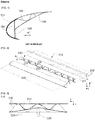
- Figure 2 corresponding for example to the leading edge of a slat, the structure of a leading edge according to the invention, comprises a spar (210) of substantially U-shaped section, and a skin (220), in partial representation in this figure, forming the leading edge.
- the skin is extended as a single piece or in several assembled parts, on the upper surface side and the lower surface side.
- the spar (210) comprises a web (211) extending in the yz plane according to this embodiment and flanges (212) on either side of the web.
- the spar (210) and the skin (220) are linked by the flanges (212) of the spar on the upper and lower surfaces by riveting or by welding depending on the embodiments.
- the spar (210) and the skin (220) are made of a metallic material, for example an aluminum alloy or are made of a composite with continuous reinforcement in a thermosetting or thermoplastic polymer matrix.
- a stiffening structure (230) extends between the skin (220) and the spar (210) it is fixed on the one hand to the web (211) of the spar and on the other hand to the inner face of the skin .
- the stiffening structure (230) is a sheet comprising a plurality of bosses (231), distributed along the length, here the y axis, of the leading edge.
- Each boss (231) forms a dome comprising, on the skin side, a zone (232) tangent to the inner surface of the skin, and in the hollow between two bumps, a zone (233) tangent to the surface of the core (211) of the spar.
- None of the sides of the domes constituting the bosses (231) is parallel to the normal to the web of the spar, so that no surface of said dome is parallel to the main component of the speed vector, directed essentially according to the x axis, of an object impacting the leading edge.
- the stiffening structure comprises 9 domes (231) distributed at a regular pitch along the y axis. It advantageously replaces 9 straight ribs between the spar and the leading edge skin.
- the pitch of the bosses is variable and preferably increases along the y axis as it moves away from the root of the element. airfoil so as to adapt the stiffening to the rigidity of said airfoil element.
- the stiffening structure consists of a sheet formed from an aluminum alloy. Such a shape is obtained by hydroforming, superplastic forming or even by incremental forming.
- the sheet has a thickness of 1 mm and weighs approximately 500 grams, thus representing a gain of 1.3 kg compared to a solution of the prior art using 9 straight ribs of 200 grams each.
- the stiffening structure (230) consists of a composite material comprising a continuous reinforcement, for example in the form of carbon fibers, in a thermoplastic polymer matrix, for example of polyetheretherketone (PEEK).
- a continuous reinforcement for example in the form of carbon fibers
- a thermoplastic polymer matrix for example of polyetheretherketone (PEEK).
- thermoplastic polymer matrix provides superior impact resistance compared to a thermosetting matrix.
- the stiffening structure (230) is advantageously assembled to the spar (210) and to the skin (220) by welding, these also being of composite structure.
- Welding is carried out by ultrasound or by bringing the assembly to be assembled to an appropriate temperature in a tool. If one of the skin or of the spar consists of a composite with a thermosetting matrix, a thermoplastic film capable of bonding with the polymer constituting the matrix of this element is deposited beforehand on the surfaces corresponding to the assembly zones.
- this film is deposited by an additive manufacturing process according to a method as described in the document EP 3,242,790 .
- the pitch of the bosses as well as the angles of their flanks are chosen so as to facilitate the passage of a fiber placement head for their production.
- leading edge structure allows both: a gain in weight, better impact resistance and stiffening better preserving the deformation compatibility between the leading edge and the wing element when this leading edge is mobile.
- the structure that is the subject of the invention opens up the possibility of producing a leading edge according to a composite construction capable of meeting the impact resistance requirements.
Landscapes
- Engineering & Computer Science (AREA)
- Aviation & Aerospace Engineering (AREA)
- Mechanical Engineering (AREA)
- Laminated Bodies (AREA)
Description
- L'invention concerne un bec de bord d'attaque de voilure d'aéronef tel qu'un bec basculant de bord d'attaque, ou « slat », dont la structure du bec est optimisée.
- Plus particulièrement l'invention concerne une structure de raidissement d'un tel bec de bord d'attaque.
- Les becs de bord d'attaque de voilure sont présents sur un aéronef tant sur les plans horizontaux, ailes et plans horizontaux de dérive, que les plans verticaux tel que sur la dérive.
- Les slats présents sur une aile d'aéronef, sont des bords d'attaque basculants qui permettent, par leur déplacement contrôlé, de modifier l'écoulement aérodynamique autour de l'aile et d'en modifier la portance à une vitesse donnée.
- Un avion de transport civil comprend généralement 3 à 5 slats répartis sur les bords d'attaque des ailes, depuis l'emplanture de l'aile jusqu'au saumon, lesquels suivent l'évolution de la section de l'aile entre ses deux extrémités.
- Un slat est ainsi une surface portante de la voilure qui peut récupérer, à une position d'envergure donnée, jusqu'à 30 % de la portance totale de la section de voilure.
- La
figure 1 représente schématiquement la section, dans le plan x-z d'un slat selon l'art antérieur. Le système d'axe représenté est celui de l'avion le fuselage s'étend parallèlement à l'axe x et la voilure essentiellement selon l'axe y. - Un tel slat comprend une peau extrados (110) s'étendant depuis le bord d'attaque (bec) jusqu'au bord de fuite. Laquelle est, selon certains modes de réalisation, constituée de plusieurs parties.
- Un longeron (120) est assemblé à la peau extrados (110) auquel sont liées des nervures.
- Une peau intérieure (130) est liée à la peau d'extrados (110) par l'intermédiaire d'un système de raidissement (140) tel que des lisses, des nervures, voire une structure en nid d'abeille selon le mode de réalisation.
- Plusieurs nervures réparties selon l'axe y, sont liées au longeron et à la peau extrados réalisant une structure en caisson, tant du côté du bord d'attaque que du côté du bord de fuite.
- Le slat est lié à l'aile par l'intermédiaire d'une ou plusieurs ferrures d'interface (non représentées) connectées par l'intermédiaire de bras ou de rails de manœuvre à des moyens actionneur mécaniques ou hydrauliques pour réaliser le déplacement relatif contrôlé du slat par rapport à l'aile.
- La structure schématiquement représentée
figure 1 correspond à un exemple de construction métallique, mais les constructions en composite de l'art antérieur sont similaires. - Cette conception mécanique a peu évolué.
- En termes de rigidité, un slat doit être suffisamment rigide pour résister aux efforts aérodynamiques.
- Les efforts aérodynamiques subis par le slat sont transférés à la voilure via les ferrures d'interface et les rails ou bras de manœuvre qui doivent être dimensionnés en conséquence selon le nombre de ferrures.
- Lorsqu'un slat est lié à l'aile par plus de deux ferrures d'interface, les différences de déformée entre l'aile et le slat produisent des surcontraintes dans les ferrures d'interface et les éléments de manœuvre, d'autant plus importantes que le nombre de ferrures d'interface est élevé.
- En effet, lorsque la liaison du slat avec l'aile comprend plus de deux ferrures, ce qui est fréquent, le montage est hyperstatique. Cet hyperstatisme combiné aux différences de déformées est responsable de la moitié des efforts auxquels sont soumises lesdites ferrures et le slat, le reste provenant du chargement aérodynamique.
- Ce phénomène oblige à dimensionner les ferrures d'interface et les moyens de manœuvre, en conséquence ce qui a influence sur la masse, et augmente les risques de grippage ou de coincement, qui doivent être pris en compte dans le dimensionnement.
- Par ailleurs, les bords d'attaques des éléments de voilure sont exposés aux chocs, notamment aux chocs avec des oiseaux.
- Dans une conception classique telle que représentée
figure 1 , la peau format le bec de bord d'attaque, est liée au longeron et raidie par des nervures droites (150) perpendiculaires au longeron. Selon des exemples de réalisation jusqu'à 18 nervures sont ainsi réparties selon l'axe y entre le longeron et la peau formant le bord d'attaque, formant ainsi une structure en caissons multiples. - Selon un exemple de réalisation d'un slat, chacune de ces nervures (150) pèse environ 200 grammes soit un poids total imputable à ce raidissement de l'ordre de 3,6 kg.
- En cas de choc, sur le bec, ces nervures droites, très rigides génèrent un transfert direct de l'énergie d'impact vers le longeron.
- La composante majoritaire de la vitesse d'impact d'un objet ou d'un oiseau sur le bord d'attaque est parallèle à l'axe x, et correspond à la vitesse de déplacement de l'aéronef.
- De par la raideur importante des nervures (150) dans la direction x, ces nervures ne favorisent pas la diffusion de l'énergie d'impact. Le risque est un endommagement du longeron.
- Dans le cas où le longeron est endommagé, la tenue résiduelle de la structure après impact est remise en cause.
- Multiplier les nervures, outre l'augmentation de la masse, augmente la rigidité du slat et réduit sa capacité à suivre les déformations de l'aile, augmentant les efforts d'interface liés aux différences de déformation entre l'aile et le slat.
- De plus, cette solution architecturale de l'art antérieur est encore plus défavorable vis-à-vis de la tenue au choc dans le cas d'une construction réalisée en matériau composite, de type de matériau présentant une capacité d'absorption d'énergie à la rupture, à rigidité égale, inférieure à celle des matériaux métalliques.
- Le document
US 9,708,030 - L'invention vise à résoudre les inconvénients de l'art antérieur et concerne à cette fin un bec de bord d'attaque d'un élément de voilure d'un aéronef, ledit aéronef définissant un repère comprenant un axe principal de fuselage x et un axe d'envergure y, l'élément de voilure procurant une portance selon un axe z, comprenant une peau formant le bec de bord d'attaque, un longeron lié à ladite peau et une structure de raidissement liée côté bord d'attaque audit longeron et à la peau, dans lequel la structure de raidissement est constituée d'une tôle formée comprenant une pluralité de bossages répartis selon la longueur du bord d'attaque, lesdits bossages s'étendant entre le longeron et la face interne de la peau et dans lequel les bossages forment des dômes comportant une zone en contact avec la peau et tangent à celle-ci, les creux entre les bossages étant en contact avec le longeron et tangents à celui-ci. En comparaison de l'art antérieur, cette structure de raidissement permet de répartir l'énergie d'impact sur une plus grande surface, limitant les risques de dégradation du longeron, mais aussi dans un volume de matière plus important, rendant cette solution compatible avec une construction composite, tout en conservant une facilité d'assemblage.
- L'invention est mise en œuvre selon les modes de réalisation et les variantes exposés ci-après, lesquels sont à considérer individuellement ou selon toute combinaison techniquement opérante.
- Selon un exemple de réalisation, ledit bec est un bec mobile de bord d'attaque ou slat. Dans cet exemple de réalisation et en comparaison de l'art antérieur, le raidissement procuré par la structure objet de l'invention est inférieur à capacité d'absorption d'impact égal, favorisant ainsi le suivi des déformations de l'aile et limitant les contraintes d'incompatibilité de déformation.
- Avantageusement, les flancs des bossages forment un angle inférieur à 90° par rapport à la surface du longeron et à la surface de la peau. L'inclinaison des flancs des bossages favorise l'absorption de l'énergie d'impact tant par la tôle de raidissement que par la peau formant le bec de bord d'attaque.
- Selon un mode de réalisation, la structure de raidissement est constituée d'un matériau composite à fibres continues dans une matrice thermoplastique. Ce mode de réalisation permet d'alléger la structure, en tirant avantage de la meilleure répartition d'énergie d'impact pour permettre une construction en matériau composite.
- Avantageusement, la peau formant le bec et le longeron sont également constitués d'un matériau composite à fibres continues et à matrice polymère, et la structure de raidissement est liée au longeron et à la peau par soudure. Ce mode de réalisation permet un gain de masse facilite les assemblages.
- Selon un mode de réalisation particulier, le pas des bossages est variable sur la longueur du bec de bord d'attaque.
- L'invention est exposée ci-après selon ses modes de réalisation préférés, nullement limitatifs, et en référence aux
figures 1 à 3 dans lesquelles ; - [
fig. 1 ] lafigure 1 relative à l'art antérieur représente, selon une vue en section, un exemple schématique de réalisation d'un slat selon l'art antérieur ; - [
fig. 2 ] la figure représente selon une vue en perspective et en éclaté, un exemple de réalisation d'un bord d'attaque selon l'invention ; - [
fig. 3 ] et lafigure 3 représente schématiquement selon un plan de coupe AA représentéfigure 2 , la réponse de la structure de lafigure 2 au cours d'un impact, avec en pointillé la forme des éléments avant impact et en trait plein la déformation de ces éléments au cours de l'impact. -
Figure 2 , selon un exemple de réalisation, correspondant par exemple au bord d'attaque d'un slat, la structure d'un bord d'attaque selon l'invention, comprend un longeron (210) de section sensiblement en forme de U, et une peau (220), en représentation partielle sur cette figure, formant le bord d'attaque. La peau se prolonge d'une seule pièce ou en plusieurs parties assemblées, côté extrados et côté intrados. - Le longeron (210) comprend une âme (211) s'étendant dans le plan y-z selon ce mode de réalisation et des semelles (212) de part et d'autre de l'âme.
- Le longeron (210) et la peau (220) sont liés par les semelles (212) du longeron côtés extrados et intrados par rivetage ou par soudage selon les modes de réalisation.
- Selon les variantes de réalisation le longeron (210) et la peau (220) sont constitués d'un matériau métallique, par exemple un alliage d'aluminium ou sont constitués d'un composite à renfort continu dans une matrice polymère thermodurcissable ou thermoplastique.
- Une structure de raidissement (230) s'étend entre la peau (220) et le longeron (210) elle est fixée d'une part à l'âme (211) du longeron et d'autre part à la face intérieure de la peau.
- La structure de raidissement (230) est une tôle comprenant une pluralité de bossages (231), répartis sur la longueur, ici l'axe y, du bord d'attaque.
- Chaque bossage (231) forme un dôme comportant, côté peau, une zone (232) tangente à la surface intérieure de la peau, et au creux entre deux bosses, une zone (233) tangente à la surface de l'âme (211) du longeron.
- Aucun des flancs des dômes constituants les bossages (231) n'est parallèle à la normale à l'âme du longeron, de sorte qu'aucune surface desdits dôme n'est parallèle à la composante principale du vecteur vitesse, dirigé essentiellement selon l'axe x, d'un objet impactant le bord d'attaque.
- Selon cet exemple de réalisation, la structure de raidissement comporte 9 dômes (231) répartis selon un pas régulier le long de l'axe y. Elle remplace avantageusement 9 nervures droites entre le longeron et la peau de bord d'attaque.
- Alternativement, le pas des bossages est variable et préférentiellement augmente selon l'axe y en s'éloignant de l'emplanture de l'élément de voilure de sorte à adapter le raidissement à la rigidité dudit élément de voilure.
- Selon un exemple de réalisation, la structure de raidissement est constituée d'une tôle formée en alliage d'aluminium. Une telle forme est obtenue par hydroformage, formage superplastique ou encore par formage incrémental.
- A titre d'exemple non limitatif, la tôle a une épaisseur de 1 mm et pèse environ 500 grammes, représentant ainsi un gain de 1,3 kg par rapport à une solution de l'art antérieur mettant en œuvre 9 nervures droites de 200 grammes chacune.
- Selon un autre mode de réalisation la structure de raidissement (230) est constituée d'un matériau composite comportant un renfort continu, par exemple sous la forme de fibres de carbone, dans une matrice polymère thermoplastique par exemple en polyétheréthercétone (PEEK).
- L'utilisation d'une matrice polymère thermoplastique assure une tenue supérieure à l'impact en comparaison d'une matrice thermodurcissable.
- Selon cette configuration composite, la structure de raidissement (230) est avantageusement assemblée au longeron (210) et à la peau (220) par soudure, ceux-ci étant également de structure composite.
- La soudure est réalisée par ultrasons ou en portant l'ensemble à assembler à une température appropriée dans un outillage. Si l'un de la peau ou du longeron est constitué d'un composite à matrice thermodurcissable, un film thermoplastique apte à se lier avec le polymère constituant la matrice de cet élément est préalablement déposé sur les surfaces correspondant aux zones d'assemblage.
- Selon un exemple de réalisation ce film est déposé par un procédé de fabrication additive selon une méthode telle que décrite dans le document
EP 3 242 790 . - Selon cet exemple de réalisation de la structure de raidissement en matériau composite, le pas des bossages ainsi que les angles de leurs flancs sont choisis de sorte à faciliter le passage d'une tête de placement de fibres pour leur réalisation.
-
Figure 3 , en cas d'impact sur la structure objet de l'invention avec une direction d'impact (300) dont la composante principale est orientée selon l'axe x, la déformation de la peau (220) sollicite la déformation de plusieurs bossages de la structure de raidissement (230) répartissant ainsi l'énergie d'impact dans un volume de matière important et l'effort de réaction sur une surface importante du longeron (210) qui est ainsi préservé. - Du fait de l'inclinaison des flancs des bossages, plus la pénétration de l'impacteur selon x est importante et plus le nombre de bossages affectés par la déformation est important, augmentant d'autant plus les capacités de dissipation de l'énergie d'impact.
- La déformation plastique de la peau (220) et de la structure de raidissement (230) lorsque celles-ci sont constituées d'un matériau métallique, ou leur dégradation par délaminage lorsqu'elles sont constituées d'un matériau composite, seuille l'effort transmis au longeron sur une grande distance de déplacement de l'impacteur, quasiment jusqu'à ce que celui-ci atteigne le longeron.
- La description ci-avant montre que la structure de bord d'attaque selon l'invention permet à la fois : un gain de masse, une meilleure tenue à l'impact et un raidissement préservant mieux la compatibilité de déformation entre le bord d'attaque et l'élément de voilure lorsque ce bord d'attaque est mobile.
- De plus, la structure objet de l'invention ouvre la possibilité de réalisation d'un bord d'attaque selon une construction composite apte à répondre aux exigences de tenue au choc.
Claims (6)
- Bec de bord d'attaque d'un élément de voilure d'un aéronef, ledit aéronef définissant un repère comprenant un axe principal de fuselage x et un axe d'envergure y, l'élément de voilure procurant une portance selon un axe z, comprenant une peau (220) formant le bec de bord d'attaque, un longeron (210) lié à ladite peau et une structure de raidissement (230) liée côté bord d'attaque audit longeron et à la peau, la structure de raidissement (230) étant constituée d'une tôle formée comprenant une pluralité de bossages (231) répartis selon la longueur du bord d'attaque, lesdits bossages s'étendant entre le longeron et la face interne de la peau, caractérisé en ce que les bossages (231) forment des dômes comportant une zone (232) en contact avec la peau et tangent à celle-ci, les creux (233) entre les bossages étant en contact avec le longeron (210) et tangents à celui-ci.
- Bec de bord d'attaque selon la revendication 1, dans lequel ledit bec est un bec mobile de bord d'attaque ou slat.
- Bec de bord d'attaque selon la revendication 1, dans lequel les flancs des bossages (231) forment un angle inférieur à 90° par rapport à la surface du longeron et à la surface de la peau avec lesquels ils sont en contact.
- Bec de bord d'attaque selon la revendication 1, dans lequel la structure de raidissement (230) est constituée d'un matériau composite à fibres continues dans une matrice thermoplastique.
- Bec de bord d'attaque selon la revendication 4, dans lequel la peau (220) formant le bec et le longeron (210) sont constitués d'un matériau composite à fibres continues dans une matrice polymère, et dans lequel la structure de raidissement (230) est liée au longeron et à la peau par soudure.
- Bec de bord d'attaque selon la revendication 1, dans lequel le pas de répartition des bossages (231) est variable sur la longueur du bec de bord d'attaque.
Applications Claiming Priority (1)
| Application Number | Priority Date | Filing Date | Title |
|---|---|---|---|
| FR1874356A FR3091263A1 (fr) | 2018-12-28 | 2018-12-28 | Bec de bord d’attaque à structure optimisée |
Publications (2)
| Publication Number | Publication Date |
|---|---|
| EP3674205A1 EP3674205A1 (fr) | 2020-07-01 |
| EP3674205B1 true EP3674205B1 (fr) | 2021-05-05 |
Family
ID=66690612
Family Applications (1)
| Application Number | Title | Priority Date | Filing Date |
|---|---|---|---|
| EP19202335.6A Active EP3674205B1 (fr) | 2018-12-28 | 2019-10-09 | Bec de bord d'attaque à structure optimisée |
Country Status (3)
| Country | Link |
|---|---|
| US (1) | US11260956B2 (fr) |
| EP (1) | EP3674205B1 (fr) |
| FR (1) | FR3091263A1 (fr) |
Families Citing this family (1)
| Publication number | Priority date | Publication date | Assignee | Title |
|---|---|---|---|---|
| EP4303122A1 (fr) * | 2022-07-07 | 2024-01-10 | Airbus Operations GmbH | Aile pour un aéronef |
Family Cites Families (15)
| Publication number | Priority date | Publication date | Assignee | Title |
|---|---|---|---|---|
| US5366177A (en) * | 1992-10-05 | 1994-11-22 | Rockwell International Corporation | Laminar flow control apparatus for aerodynamic surfaces |
| JP3647612B2 (ja) * | 1997-07-24 | 2005-05-18 | 富士重工業株式会社 | 航空機の前縁構造及びその製造方法 |
| JP3973474B2 (ja) * | 2002-04-05 | 2007-09-12 | 日本飛行機株式会社 | 航空機翼前縁部の製造方法 |
| US20040237763A1 (en) * | 2003-06-02 | 2004-12-02 | Ashok Bhatnagar | Corrugated ballistic armor |
| DE602005002144D1 (de) * | 2004-05-13 | 2007-10-04 | Airbus Gmbh | Flugzeugbauteil, insbesondere flügel |
| DE102004029485B4 (de) * | 2004-06-18 | 2007-05-31 | Eads Deutschland Gmbh | Impuls-absorbierendes Struktur-Bauteil |
| DE102007038634B3 (de) * | 2007-08-16 | 2008-07-31 | Eads Deutschland Gmbh | Impuls-absorbierendes Struktur-Bauteil |
| GB0720387D0 (en) * | 2007-10-18 | 2007-11-28 | Airbus Uk Ltd | Panel with impact protection membrane |
| GB0900494D0 (en) * | 2009-01-14 | 2009-02-11 | Airbus Uk Ltd | Aerofoil Structure |
| US10556670B2 (en) * | 2010-08-15 | 2020-02-11 | The Boeing Company | Laminar flow panel |
| DE102011101303A1 (de) * | 2011-05-12 | 2012-11-15 | Eads Deutschland Gmbh | Schlagschutzplatte für Fahrzeuge, insbesondere Luftfahrzeuge |
| US9708030B1 (en) * | 2011-12-08 | 2017-07-18 | The Boeing Company | Impact-energy tolerant method and structures |
| JP6238168B2 (ja) * | 2014-02-04 | 2017-11-29 | 三菱重工業株式会社 | 複合材構造 |
| FR3031471A1 (fr) | 2015-01-09 | 2016-07-15 | Daher Aerospace | Procede pour la fabrication d’un piece composite complexe, notamment a matrice thermoplastique et piece obtenue par un tel procede |
| GB201522327D0 (en) * | 2015-12-17 | 2016-02-03 | Airbus Operations Ltd | Wing structure |
-
2018
- 2018-12-28 FR FR1874356A patent/FR3091263A1/fr not_active Withdrawn
-
2019
- 2019-10-09 EP EP19202335.6A patent/EP3674205B1/fr active Active
- 2019-12-26 US US16/727,189 patent/US11260956B2/en active Active
Also Published As
| Publication number | Publication date |
|---|---|
| US11260956B2 (en) | 2022-03-01 |
| EP3674205A1 (fr) | 2020-07-01 |
| US20200207458A1 (en) | 2020-07-02 |
| FR3091263A1 (fr) | 2020-07-03 |
Similar Documents
| Publication | Publication Date | Title |
|---|---|---|
| BE1015867A3 (fr) | Ensemble de bord d'attaque d'un element de voilure d'aeronef et element de voilure equipee d'au moins un tel ensemble. | |
| EP2363342B1 (fr) | Pale à vrillage adaptatif, et rotor muni d'une telle pale | |
| EP2653377B1 (fr) | Surface aérodynamique portante d'aéronef, et aéronef muni de ladite surface aérodynamique portante | |
| EP2242683B1 (fr) | Panneau composite monolithique auto-raidi et pivotant, notamment pour une partie mobile d'aeronef | |
| FR2993942A1 (fr) | Aube composite de turbomachine a renfort structurel | |
| WO2022018357A1 (fr) | Turbomachine d'aeronef comportant des aubes d'helice a calage variable | |
| EP2818408B1 (fr) | Pale à rigidité en torsion réduite et rotor muni d'une telle pale | |
| WO2017055727A1 (fr) | Aube comprenant un bouclier de bord d'attaque et procede de fabrication de l'aube | |
| EP3674205B1 (fr) | Bec de bord d'attaque à structure optimisée | |
| EP1768898B1 (fr) | Volet mobile de bord d'attaque d'une aile principale de la voilure d'un aeronef | |
| CA2951757C (fr) | Procede d'assemblage d'un ensemble de pieces composites et ensemble obtenu par un tel procede | |
| FR3069185A1 (fr) | Profil aerodynamique a noyau creux oblong arrondi en materiau composite renforce par un textile a fibres unidirectionnelles | |
| EP2692631B1 (fr) | Cadre de fuselage d'aéronef à section évolutive | |
| EP3521173B1 (fr) | Ensemble pour aeronef comprenant une structure primaire de mat d'accrochage fixee a un caisson de voilure a l'aide d'une liaison boulonnee | |
| EP4313574A1 (fr) | Aube comprenant une structure en matériau composite et procédé de fabrication associé | |
| EP3670331B1 (fr) | Elément de voilure avec un elément mobile | |
| EP1961658B1 (fr) | Pale de giravion pourvue d'un tronçon radial et d'au moins un tronçon en fléche avant et/ou arrière | |
| WO2022184997A1 (fr) | Aube comprenant une structure en matériau composite et procédé de fabrication associé | |
| EP3287363B1 (fr) | Extension de voilure pour une aile d'aeronef | |
| FR2991287A1 (fr) | Avion a voilure haubanee sans caisson central | |
| FR3085414A1 (fr) | Aube de turbomachine comportant une liaison au renfort structurel a inserts et evidements | |
| EP4061702B1 (fr) | Element aerodynamique comportant deux pieces aerodynamiques formant une jonction de profil ascendant |
Legal Events
| Date | Code | Title | Description |
|---|---|---|---|
| PUAI | Public reference made under article 153(3) epc to a published international application that has entered the european phase |
Free format text: ORIGINAL CODE: 0009012 |
|
| STAA | Information on the status of an ep patent application or granted ep patent |
Free format text: STATUS: REQUEST FOR EXAMINATION WAS MADE |
|
| 17P | Request for examination filed |
Effective date: 20191009 |
|
| AK | Designated contracting states |
Kind code of ref document: A1 Designated state(s): AL AT BE BG CH CY CZ DE DK EE ES FI FR GB GR HR HU IE IS IT LI LT LU LV MC MK MT NL NO PL PT RO RS SE SI SK SM TR |
|
| AX | Request for extension of the european patent |
Extension state: BA ME |
|
| GRAP | Despatch of communication of intention to grant a patent |
Free format text: ORIGINAL CODE: EPIDOSNIGR1 |
|
| STAA | Information on the status of an ep patent application or granted ep patent |
Free format text: STATUS: GRANT OF PATENT IS INTENDED |
|
| INTG | Intention to grant announced |
Effective date: 20201125 |
|
| GRAS | Grant fee paid |
Free format text: ORIGINAL CODE: EPIDOSNIGR3 |
|
| GRAA | (expected) grant |
Free format text: ORIGINAL CODE: 0009210 |
|
| STAA | Information on the status of an ep patent application or granted ep patent |
Free format text: STATUS: THE PATENT HAS BEEN GRANTED |
|
| AK | Designated contracting states |
Kind code of ref document: B1 Designated state(s): AL AT BE BG CH CY CZ DE DK EE ES FI FR GB GR HR HU IE IS IT LI LT LU LV MC MK MT NL NO PL PT RO RS SE SI SK SM TR |
|
| REG | Reference to a national code |
Ref country code: GB Ref legal event code: FG4D Free format text: NOT ENGLISH |
|
| REG | Reference to a national code |
Ref country code: CH Ref legal event code: EP |
|
| REG | Reference to a national code |
Ref country code: AT Ref legal event code: REF Ref document number: 1389508 Country of ref document: AT Kind code of ref document: T Effective date: 20210515 |
|
| REG | Reference to a national code |
Ref country code: IE Ref legal event code: FG4D Free format text: LANGUAGE OF EP DOCUMENT: FRENCH |
|
| REG | Reference to a national code |
Ref country code: DE Ref legal event code: R096 Ref document number: 602019004469 Country of ref document: DE |
|
| REG | Reference to a national code |
Ref country code: NL Ref legal event code: FP |
|
| REG | Reference to a national code |
Ref country code: LT Ref legal event code: MG9D |
|
| REG | Reference to a national code |
Ref country code: AT Ref legal event code: MK05 Ref document number: 1389508 Country of ref document: AT Kind code of ref document: T Effective date: 20210505 |
|
| PG25 | Lapsed in a contracting state [announced via postgrant information from national office to epo] |
Ref country code: HR Free format text: LAPSE BECAUSE OF FAILURE TO SUBMIT A TRANSLATION OF THE DESCRIPTION OR TO PAY THE FEE WITHIN THE PRESCRIBED TIME-LIMIT Effective date: 20210505 Ref country code: LT Free format text: LAPSE BECAUSE OF FAILURE TO SUBMIT A TRANSLATION OF THE DESCRIPTION OR TO PAY THE FEE WITHIN THE PRESCRIBED TIME-LIMIT Effective date: 20210505 Ref country code: FI Free format text: LAPSE BECAUSE OF FAILURE TO SUBMIT A TRANSLATION OF THE DESCRIPTION OR TO PAY THE FEE WITHIN THE PRESCRIBED TIME-LIMIT Effective date: 20210505 Ref country code: AT Free format text: LAPSE BECAUSE OF FAILURE TO SUBMIT A TRANSLATION OF THE DESCRIPTION OR TO PAY THE FEE WITHIN THE PRESCRIBED TIME-LIMIT Effective date: 20210505 Ref country code: BG Free format text: LAPSE BECAUSE OF FAILURE TO SUBMIT A TRANSLATION OF THE DESCRIPTION OR TO PAY THE FEE WITHIN THE PRESCRIBED TIME-LIMIT Effective date: 20210805 |
|
| PG25 | Lapsed in a contracting state [announced via postgrant information from national office to epo] |
Ref country code: PL Free format text: LAPSE BECAUSE OF FAILURE TO SUBMIT A TRANSLATION OF THE DESCRIPTION OR TO PAY THE FEE WITHIN THE PRESCRIBED TIME-LIMIT Effective date: 20210505 Ref country code: LV Free format text: LAPSE BECAUSE OF FAILURE TO SUBMIT A TRANSLATION OF THE DESCRIPTION OR TO PAY THE FEE WITHIN THE PRESCRIBED TIME-LIMIT Effective date: 20210505 Ref country code: NO Free format text: LAPSE BECAUSE OF FAILURE TO SUBMIT A TRANSLATION OF THE DESCRIPTION OR TO PAY THE FEE WITHIN THE PRESCRIBED TIME-LIMIT Effective date: 20210805 Ref country code: PT Free format text: LAPSE BECAUSE OF FAILURE TO SUBMIT A TRANSLATION OF THE DESCRIPTION OR TO PAY THE FEE WITHIN THE PRESCRIBED TIME-LIMIT Effective date: 20210906 Ref country code: RS Free format text: LAPSE BECAUSE OF FAILURE TO SUBMIT A TRANSLATION OF THE DESCRIPTION OR TO PAY THE FEE WITHIN THE PRESCRIBED TIME-LIMIT Effective date: 20210505 Ref country code: SE Free format text: LAPSE BECAUSE OF FAILURE TO SUBMIT A TRANSLATION OF THE DESCRIPTION OR TO PAY THE FEE WITHIN THE PRESCRIBED TIME-LIMIT Effective date: 20210505 Ref country code: IS Free format text: LAPSE BECAUSE OF FAILURE TO SUBMIT A TRANSLATION OF THE DESCRIPTION OR TO PAY THE FEE WITHIN THE PRESCRIBED TIME-LIMIT Effective date: 20210905 Ref country code: GR Free format text: LAPSE BECAUSE OF FAILURE TO SUBMIT A TRANSLATION OF THE DESCRIPTION OR TO PAY THE FEE WITHIN THE PRESCRIBED TIME-LIMIT Effective date: 20210806 |
|
| PG25 | Lapsed in a contracting state [announced via postgrant information from national office to epo] |
Ref country code: ES Free format text: LAPSE BECAUSE OF FAILURE TO SUBMIT A TRANSLATION OF THE DESCRIPTION OR TO PAY THE FEE WITHIN THE PRESCRIBED TIME-LIMIT Effective date: 20210505 Ref country code: EE Free format text: LAPSE BECAUSE OF FAILURE TO SUBMIT A TRANSLATION OF THE DESCRIPTION OR TO PAY THE FEE WITHIN THE PRESCRIBED TIME-LIMIT Effective date: 20210505 Ref country code: SK Free format text: LAPSE BECAUSE OF FAILURE TO SUBMIT A TRANSLATION OF THE DESCRIPTION OR TO PAY THE FEE WITHIN THE PRESCRIBED TIME-LIMIT Effective date: 20210505 Ref country code: CZ Free format text: LAPSE BECAUSE OF FAILURE TO SUBMIT A TRANSLATION OF THE DESCRIPTION OR TO PAY THE FEE WITHIN THE PRESCRIBED TIME-LIMIT Effective date: 20210505 Ref country code: DK Free format text: LAPSE BECAUSE OF FAILURE TO SUBMIT A TRANSLATION OF THE DESCRIPTION OR TO PAY THE FEE WITHIN THE PRESCRIBED TIME-LIMIT Effective date: 20210505 Ref country code: RO Free format text: LAPSE BECAUSE OF FAILURE TO SUBMIT A TRANSLATION OF THE DESCRIPTION OR TO PAY THE FEE WITHIN THE PRESCRIBED TIME-LIMIT Effective date: 20210505 Ref country code: SM Free format text: LAPSE BECAUSE OF FAILURE TO SUBMIT A TRANSLATION OF THE DESCRIPTION OR TO PAY THE FEE WITHIN THE PRESCRIBED TIME-LIMIT Effective date: 20210505 |
|
| REG | Reference to a national code |
Ref country code: DE Ref legal event code: R097 Ref document number: 602019004469 Country of ref document: DE |
|
| PLBE | No opposition filed within time limit |
Free format text: ORIGINAL CODE: 0009261 |
|
| STAA | Information on the status of an ep patent application or granted ep patent |
Free format text: STATUS: NO OPPOSITION FILED WITHIN TIME LIMIT |
|
| 26N | No opposition filed |
Effective date: 20220208 |
|
| PG25 | Lapsed in a contracting state [announced via postgrant information from national office to epo] |
Ref country code: IS Free format text: LAPSE BECAUSE OF FAILURE TO SUBMIT A TRANSLATION OF THE DESCRIPTION OR TO PAY THE FEE WITHIN THE PRESCRIBED TIME-LIMIT Effective date: 20210905 Ref country code: AL Free format text: LAPSE BECAUSE OF FAILURE TO SUBMIT A TRANSLATION OF THE DESCRIPTION OR TO PAY THE FEE WITHIN THE PRESCRIBED TIME-LIMIT Effective date: 20210505 |
|
| PG25 | Lapsed in a contracting state [announced via postgrant information from national office to epo] |
Ref country code: MC Free format text: LAPSE BECAUSE OF FAILURE TO SUBMIT A TRANSLATION OF THE DESCRIPTION OR TO PAY THE FEE WITHIN THE PRESCRIBED TIME-LIMIT Effective date: 20210505 |
|
| PG25 | Lapsed in a contracting state [announced via postgrant information from national office to epo] |
Ref country code: LU Free format text: LAPSE BECAUSE OF NON-PAYMENT OF DUE FEES Effective date: 20211009 Ref country code: IT Free format text: LAPSE BECAUSE OF FAILURE TO SUBMIT A TRANSLATION OF THE DESCRIPTION OR TO PAY THE FEE WITHIN THE PRESCRIBED TIME-LIMIT Effective date: 20210505 |
|
| REG | Reference to a national code |
Ref country code: CH Ref legal event code: PL |
|
| PG25 | Lapsed in a contracting state [announced via postgrant information from national office to epo] |
Ref country code: CY Free format text: LAPSE BECAUSE OF FAILURE TO SUBMIT A TRANSLATION OF THE DESCRIPTION OR TO PAY THE FEE WITHIN THE PRESCRIBED TIME-LIMIT Effective date: 20210505 |
|
| PG25 | Lapsed in a contracting state [announced via postgrant information from national office to epo] |
Ref country code: LI Free format text: LAPSE BECAUSE OF NON-PAYMENT OF DUE FEES Effective date: 20221031 Ref country code: HU Free format text: LAPSE BECAUSE OF FAILURE TO SUBMIT A TRANSLATION OF THE DESCRIPTION OR TO PAY THE FEE WITHIN THE PRESCRIBED TIME-LIMIT; INVALID AB INITIO Effective date: 20191009 Ref country code: CH Free format text: LAPSE BECAUSE OF NON-PAYMENT OF DUE FEES Effective date: 20221031 |
|
| PGFP | Annual fee paid to national office [announced via postgrant information from national office to epo] |
Ref country code: NL Payment date: 20231031 Year of fee payment: 5 |
|
| PGFP | Annual fee paid to national office [announced via postgrant information from national office to epo] |
Ref country code: GB Payment date: 20231027 Year of fee payment: 5 |
|
| PGFP | Annual fee paid to national office [announced via postgrant information from national office to epo] |
Ref country code: IE Payment date: 20231021 Year of fee payment: 5 Ref country code: FR Payment date: 20231027 Year of fee payment: 5 Ref country code: DE Payment date: 20231027 Year of fee payment: 5 |
|
| PGFP | Annual fee paid to national office [announced via postgrant information from national office to epo] |
Ref country code: BE Payment date: 20231031 Year of fee payment: 5 |
|
| PG25 | Lapsed in a contracting state [announced via postgrant information from national office to epo] |
Ref country code: MK Free format text: LAPSE BECAUSE OF FAILURE TO SUBMIT A TRANSLATION OF THE DESCRIPTION OR TO PAY THE FEE WITHIN THE PRESCRIBED TIME-LIMIT Effective date: 20210505 |
|
| PG25 | Lapsed in a contracting state [announced via postgrant information from national office to epo] |
Ref country code: MT Free format text: LAPSE BECAUSE OF FAILURE TO SUBMIT A TRANSLATION OF THE DESCRIPTION OR TO PAY THE FEE WITHIN THE PRESCRIBED TIME-LIMIT Effective date: 20210505 |