EP1768898B1 - Bewegliche vorderkantenklappe für einen hauptflügel der tragflächen eines flugzeugs - Google Patents
Bewegliche vorderkantenklappe für einen hauptflügel der tragflächen eines flugzeugs Download PDFInfo
- Publication number
- EP1768898B1 EP1768898B1 EP05761099A EP05761099A EP1768898B1 EP 1768898 B1 EP1768898 B1 EP 1768898B1 EP 05761099 A EP05761099 A EP 05761099A EP 05761099 A EP05761099 A EP 05761099A EP 1768898 B1 EP1768898 B1 EP 1768898B1
- Authority
- EP
- European Patent Office
- Prior art keywords
- leading edge
- ribs
- flap
- coating
- extrados
- Prior art date
- Legal status (The legal status is an assumption and is not a legal conclusion. Google has not performed a legal analysis and makes no representation as to the accuracy of the status listed.)
- Expired - Lifetime
Links
Images


Classifications
-
- B—PERFORMING OPERATIONS; TRANSPORTING
- B64—AIRCRAFT; AVIATION; COSMONAUTICS
- B64C—AEROPLANES; HELICOPTERS
- B64C9/00—Adjustable control surfaces or members, e.g. rudders
- B64C9/14—Adjustable control surfaces or members, e.g. rudders forming slots
- B64C9/22—Adjustable control surfaces or members, e.g. rudders forming slots at the front of the wing
-
- Y—GENERAL TAGGING OF NEW TECHNOLOGICAL DEVELOPMENTS; GENERAL TAGGING OF CROSS-SECTIONAL TECHNOLOGIES SPANNING OVER SEVERAL SECTIONS OF THE IPC; TECHNICAL SUBJECTS COVERED BY FORMER USPC CROSS-REFERENCE ART COLLECTIONS [XRACs] AND DIGESTS
- Y02—TECHNOLOGIES OR APPLICATIONS FOR MITIGATION OR ADAPTATION AGAINST CLIMATE CHANGE
- Y02T—CLIMATE CHANGE MITIGATION TECHNOLOGIES RELATED TO TRANSPORTATION
- Y02T50/00—Aeronautics or air transport
- Y02T50/40—Weight reduction
Definitions
- the present invention relates generally to a movable flap leading edge of a main wing of the wing of an aircraft, this flap comprising in particular an aerodynamic coating having a frontal zone, said area sensitive to bird strikes.
- This type of movable shutter is designed to limit the damage it could suffer following the impact of a bird in cruising flight, on the ground during operations of maneuvering the aircraft, or during phases take off and landing.
- this movable flap is intended to constitute all or part of the leading edge of a main wing of the wing of the aircraft.
- each of the two main wings of the wing is generally equipped with high-lift movable flaps, mounted on the leading edge and the trailing edge of the wing.
- the flaps are deployed for the landing and takeoff phases to increase the lift at low or medium speed.
- the movable flaps are retracted to limit the resistance to the advancement of the aircraft.
- the displacement of each shutter is effected by means of mechanisms housed in a front part of a main central portion of the wing, these mechanisms cooperating with ribs for introducing strut forces spaced along a longitudinal direction of edge driving, and in particular being dimensioned to maintain the flap in position during the various phases of flight, as well as to ensure the transmission of aerodynamic forces to this central central portion of the wing.
- Such a movable leading edge flap must be designed so as to be able to withstand the impact of a bird occurring on it during cruising flight, on the ground during operations of maneuvering the aircraft, or even during the take-off and landing phases.
- the component must be sufficiently strong so that the deterioration of the latter, generated during this type of impact, leads only to minimal and non-catastrophic consequences for the latter, and more generally for the entire aircraft.
- this frontal zone is also called “zone sensitive to the impacts of birds", insofar as it corresponds to the most critical zone of this aerodynamic coating in the event of impact of bird occurring on the latter.
- This frontal area of aerodynamic coating relatively little inclined relative to the vertical and extending in a limited way upwards and possibly downwards from a junction between an upper portion and a lower portion of the aerodynamic coating, is indeed described as sensitive because when it is impacted by a bird, the shock produces a very important energy mainly transmitted to the flap.
- the moving flaps must be made to support the energy of a bird's impact, which is proportional to the square of the speed of the aircraft.
- prior art is known movable leading edge flaps with structures designed to limit the destructive effects likely to be caused by a bird strike in the frontal area of the aerodynamic coating, but whose complexity and / or weight generates significant disadvantages in terms of cost and overall weight of the component.
- the mass of the flap is often penalized by the presence of a large number of ribs, which are distributed in force introduction ribs and shaped ribs which are all secured to the frontal area of the aerodynamic coating.
- the force introduction ribs are deemed necessary for the transmission of forces towards the main central portion of the wing, and also necessary to obtain a satisfactory overall strength.
- the shape ribs which strongly penalize the overall mass of the movable flap, are certainly also intended to ensure satisfactory overall strength, but above all present to allow maintenance of the shape of the outer contour of the movable flap, during the different phases. flight of the aircraft.
- a stiff primary structure without rib comprises two upper and lower sandwich panels connected by longitudinal members placed diagonally on the inside of the structure, and on the other hand substantially vertically close to the front portion of the structure. leading edge.
- This subassembly is fixed continuously at the rear to a central box of the wing, and at the front to an aerodynamic cowling forming at least partially the leading edge of this wing.
- the purpose of the invention is therefore to propose a movable leading edge flap of a main wing of the wing of an aircraft, comprising in particular an aerodynamic coating having a frontal zone, this flap at least partially overcoming the disadvantages mentioned above. above relative to the achievements of the prior art.
- the subject of the invention is a movable leading edge flap of a main wing of the wing of an aircraft, this flap comprising an aerodynamic covering having a frontal zone, an extrados portion as well as a portion intrados, and also comprising a plurality of force introduction ribs spaced along a longitudinal direction of leading edge.
- the force introduction ribs each have an upper portion and a lower portion respectively integral with said upper and lower portions of the aerodynamic coating, and each of these ribs also has a front portion spaced from the frontal area of the aerodynamic coating.
- the movable flap according to the invention incorporates force introduction ribs which are designed and positioned so that during a bird strike occurring on the zone frontal aerodynamic coating, it can deform significantly without these ribs do not oppose the deformation encountered.
- the front portion of each force introduction rib being located at a distance from the front zone of the coating, this coating is therefore able to deform freely in large proportions towards the interior of the flap.
- the aerodynamic coating can deform freely beyond the front portions of these ribs.
- the movable leading edge flap is designed so that the aerodynamic coating is able to deform to penetrate inside a space between two directly consecutive ribs, and without encountering any obstacle.
- the latter is then capable of deforming continuously in large proportions in the longitudinal direction of the leading edge, as well as towards the inside the mobile shutter.
- the elastically and plastically deformed coating ends up bearing against the front part of these ribs, through which the forces related to the impact can then pass.
- these ribs may contribute to absorbing some of the remaining impact energy, possibly in combination with a multicellular background.
- the forces passing through the force introduction ribs are transmitted to the main central portion of the wing, via fastening means belonging to these same ribs and to ensure the connection between the movable flap and mechanisms of displacement of the latter.
- another advantage of the invention lies in the fact that the shape of the ribs encountered in the prior art can be removed, they clearly preventing the aerodynamic coating to deform freely to absorb a portion of the shock energy.
- adequate sizing of the aerodynamic coating particularly with regard to its thickness, allows it to have a rigidity such that the presence of shaped ribs is effectively no longer required to maintain the shape. of this coating during the different flight phases of the aircraft.
- the leading edge moving flap is able to present a simplified and lightened design compared to those previously encountered, while being able to withstand the destructive effects that can be generated by the impact of a bird occurring on the frontal area.
- the mobile component according to the invention makes it possible to avoid the catastrophic consequences that such a shock would be likely to cause.
- the coating will therefore preferably be made in a ductile material providing such behavior, such as a metal material, for example aluminum or one of its alloys.
- a material of the type "Glare”, namely an aluminum laminate / glass fabric More generally, it is retained a ductile material that tolerates large elastoplastic deformations before rupture (more than 5%).
- the movable leading edge flap comprises a multicellular rear structure located in contact with and behind the force introduction ribs.
- the multicellular rear-structure takes part in the recovery of the forces created during a bird strike occurring on the aerodynamic coating, and thus contributes to ensuring a good transmission of forces through the different components of the movable flap. Indeed, throughout the deformation phase of the aerodynamic coating and to the contact of the latter with the front portions of the force introduction ribs, the intrinsic rigidity of the multicellular rear structure allows an introduction of forces in each of the ribs , as well as the passage of these forces to the mechanisms of movement of the movable flap, and therefore to the main central portion of the wing.
- the multicellular back-structure preferably made of composite materials, thus provides additional rigidity to the movable flap, which in particular makes it possible to provide this shutter with sufficient overall mechanical strength after the impact of a bird having driven deformation of the aerodynamic coating.
- this multicellular rear structure preferably continuously supports the aerodynamic coating, the sizing of this rear structure being adapted to allow large deformations of the aerodynamic coating.
- the multicellular rear-structure comprises an extrados portion assembled to the extrados portion of the aerodynamic coating, as well as a rear coating constituting a rear coating of the flap and being assembled to a rear portion of each of the force introduction ribs.
- this rear coating extends to a trailing edge of the upper portion of the multicellular rear structure.
- the upper portion of the multicellular rear-structure is continuously assembled to the upper portion of the aerodynamic coating, and extends to a trailing edge of the spout of the movable flap. leading edge.
- the rear coating of the rear structure is assembled continuously to the intrados portion of the aerodynamic coating.
- the two extrados portions assembled to one another continuously over the entire span of the leading edge flap, are also assembled on the upper part of each of the ribs. introduction of forces, the two extrados portions being for example arranged so as to overlap, while forming a continuous aerodynamic outer surface.
- the multicellular rear structure may comprise a set of boxes located between the rear cover and the upper portion of the multicellular rear structure, this set of boxes then being located at the rear of an upper rear portion of each of the ribs. effort introduction.
- This multicellular back-structure is in this case preferentially made of a single held by vacuum injection, (of the English "Resin Transfer Molding").
- honeycomb core situated between the rear coating and the extrados portion of the multicellular rear structure, this honeycomb core then being able to be located in contact with each other. an upper rear portion of each of the force introduction ribs.
- the movable flap of leading edge further comprises a lower stiffener extending in the longitudinal direction of the leading edge, this lower stiffener providing a connection between the intrados portion of the aerodynamic coating, and the rear coating of the multicellular back-structure.
- This lower stiffener advantageously has an L-shaped cross section, the rear part of each of the force introduction ribs resting on the lateral branch of the L, and the lower portion of the aerodynamic coating resting on the base of the L. configuration, the lateral branch of the L is interposed between the rear portion of each of the force introduction ribs, and the rear coating of the rear structure.
- the movable flap may also comprise an upper stiffener extending in the longitudinal direction of leading edge, this upper stiffener being in contact with the front part and the upper part of each of the ribs of introduction of efforts.
- this upper stiffener supported and assembled on the force introduction ribs is capable of ensuring the junction between the upper portion of the aerodynamic coating, and the upper portion of the multicellular rear structure.
- the moving edge flap is then designed such that the distance X1 is between one and a half times and twice the length X2.
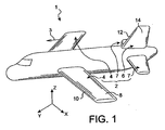
- front and rear are to be considered in relation to a direction of advancement of the aircraft encountered following the thrust exerted by the engines of the aircraft, this direction being represented schematically by the arrow 3.
- each of the two main wings 4 is capable of being equipped with at least one movable flap of the leading edge according to the invention, as will be explained in detail below for one of the two main wings 4.
- main wings 4 each comprise a main central portion 8 constituting almost the entire wing, and being located behind a leading edge 10.
- X is the longitudinal direction of the leading edge
- Y the direction oriented transversely to the leading edge 10 of the wing 4
- Z the vertical direction
- each of the two main wings 4 which can be achieved using at least one moving edge flap 16 object of the present invention, and four embodiments of which preferred will be described below.
- the movable leading edge flap 16 represented only schematically, can occupy a retracted / retracted position in which it marries the front portion of the main central portion 8 of the flange 4, as is shown in solid lines.
- the dotted lines represent the movable flap 16 in its fully deployed position where it is remote from the main central portion 8, this deployed position being adopted during the landing and takeoff phases in order to increase the lift to low or medium speed.
- the wing 4 comprises displacement mechanisms 17 integrated in the front part of the main central portion 8, these mechanisms 17 being well known to the skilled in the art and usually comprising rails.
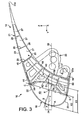
- a moving edge flap 16 is shown according to a first preferred embodiment of the present invention.
- the mobile flap 16 extends for example over substantially the entire length of the wing 4 concerned, of course along the longitudinal direction of the leading edge X, comparable to a wing direction 4.
- the main central portion 8 of the wing 4 has not been shown, but it can of course be carried out according to any configuration known to those skilled in the art.
- the movable flap of leading edge 16 comprises an aerodynamic coating 18, possibly made with the aid of several elements secured and extending in the direction X, and defining a lower portion 20 as well as an extrados portion 22.
- the coating 18 has a frontal area sensitive to bird strikes 24, this zone 24 being as described in the prior art part. More precisely, but always as an indication, it extends between a point A corresponding to the furthest point of the coating 18 in the cruising phase when the flap 16 is fully retracted (as represented on this figure 3 ), and a point B corresponding to the furthest point of the coating 18 in the landing phase when the flap 16 is fully deployed.
- the point A is on a geometric string 26 of the main wing 4, while the point B is on the extrados portion 22.
- the "geometric chord 26" is to be understood as being the line segment connecting the most forward point and the rearmost point of the section of this main wing 4, this section being taken according to any orthogonal plane.
- the rope 26 is the line segment connecting a point (the point A) establishing the front junction between the intrados and the extrados of the wing and a point (not shown) establishing the rear junction between these same intrados and extrados, always in any section of the wing 4 taken along a plane YZ.
- the flap 16 of the first preferred embodiment has a rear portion 19 which is entirely constituted by a multicellular structure 21.
- This multicellular structure 21 has an extrados portion 23, and a coating rear 28 which extends rearwardly to a trailing edge 23a of the upper portion 23.
- the rear coating 28 of the rear structure 21 is therefore intended to close the rear part of the flap 16, since it also extends to the level of the lower portion 20 of the coating 18, close to an edge of leak 20a thereof, as will be described later. It is specified that the rear coating 28, extending all along the flap 16 in the X direction, has known manner a forward curvature allowing it to marry a complementary geometry portion belonging to the central portion. main wing 4, and slide on it.
- the extrados portion 23 of the multicellular rear-structure 21 stops just at near a trailing edge of the latter, always so that these two portions 22, 23 jointly define a substantially continuous aerodynamic outer surface.
- the mechanical junction between the two extrados portions 22, 23 is then made using a doubler on which they are each assembled, as will be explained in more detail below.
- the extrados portion 23 of the multicellular rear-structure 21 could also extend forward until it straddles the upper portion 22 of the coating 18 to which this portion 23 is fixed, by example using conventional assembly means of the rivet type.
- the two extrados portions 22, 23 jointly forming the entire extrados of the flap 16 overlap so as to define a continuous aerodynamic outer surface.
- they also extend along the flap 16, in the X direction.
- the rear coating 28 and the extrados portion 23 are secured to two end ribs 32 closing on either side the space delimited by these same elements 23, 28 as well as by the coating 18, using conventional means and known to those skilled in the art.
- the multicellular rear-structure 21 also comprises a set of boxes 25 located between the rear coating 28 and the upper portion 23. More specifically, in this first preferred embodiment, the set of boxes 25 presents a plurality of boxes 27 which each extend in the direction X, preferably all along the flap 16. Each box 27 is delimited upwards by the extrados portion 23, downwards by the coating 28, and towards the front and rear by sails 29. In the example shown on the figures 2 and 3 there are three boxes 27 which follow one another from front to rear, the box 27 located at the rear being close to the trailing edge 23a. Naturally, the number of boxes 27 can be adapted according to the needs encountered.
- the boxes 27 are only at the rear of the rear structure 21.
- the front parts of the elements 23, 28 make it possible to make connections between the multicellular rear-structure 21 and the other constituent elements of the flap 16, such as the connection between the extrados portions 22 and 23 which has been explained above.
- the entire multicellular back-structure 21 is preferably made in one piece of composite materials based on carbon fibers, molded using the technique of vacuum injection, called RTM technique. 'English' Resin Transfer Molding "). This technique involves placing a carbon reinforcement in a mold, where it is impregnated with a synthetic resin under pressure and at high temperature. This technique is advantageous in that it makes it possible to obtain the complete shape of the multicellular rear-structure 21, in a reduced manufacturing time.
- the multicellular rear-structure 21 by separately making two skins of synthetic impregnated carbon frames and longitudinal sails of the same nature, then to assemble these various elements, by example by a bonding technique known to those skilled in the art.
- a bonding technique known to those skilled in the art.
- these different techniques there is that of bonding composites made of pre-impregnated materials, or that of welding thermoplastic resin composites.
- the flap 16 comprises a plurality of force introduction ribs 34, 40 spaced along the direction X, and therefore located between the end ribs 32.
- the ribs 34, 40 are preferably all oriented vertically according to the transverse direction Y, namely in a plane YZ. In addition, they are also preferably made according to the RTM technique, described above.
- two force introduction ribs 34 provided with attachment means 36 are provided to ensure the connection between the flap 16, and the movement mechanisms of the latter secured to the main central portion 8 of the wing 4.
- passages 38 are formed on the rear coating 28, so that the fastening means 36 can pass therethrough.
- an intermediate force introduction rib 40 is interposed between the two ribs 34, in order to increase the rigidity of the flap 16, and more specifically to impose on the latter, when the latter is in the retracted / retracted position, the same deformed as the whole of the main wing 4. Still in this retracted / retracted position, the intermediate force introduction rib 40 thus effectively allows, in the same way as the other ribs d introduction 34, to transmit forces to the main central portion 8 of the wing 4.
- this intermediate rib 40 differs from the ribs 34 only in that it does not bear fastening means 36, but a simple hook 37 intended to cooperate with the main central portion 8, building on it .
- this number of ribs can be adapted according to the conditions required for the support of the moving edge flap.
- these ribs 34, 40 assembled on the multicellular rear-structure 21 are provided so that the forces resulting from a bird's impact and which solicit this rear-structure 21 can pass to the movement mechanisms of the flap 16.
- the movable flap comprises in total only five transverse ribs, including three force introduction ribs 34, 40 allowing the deformation of the aerodynamic coating 18 when a bird's impact as will be explained hereinafter, and of which two end ribs 32.
- Each of the force introduction ribs 34, 40 has five distinct parts connected to each other. Indeed, as can be seen on rib 40 of the figure 3 , it comprises successively in the clockwise direction, a portion or front surface 42, an upper portion or surface 44, an upper rear portion or surface 46, a rear portion or surface 48, and finally a lower portion or surface 50. later, the cooperation between these different parts and the other constituent elements of the flap 16 will be described with reference to the rib 40, but it should be understood that it is the same for each of the force introduction ribs 34, 40.
- front portion 42 of the rib 40 is located opposite and at a distance from the frontal zone 24 of the aerodynamic lining 18, as is clearly shown on FIG. figure 3 .
- the coating 18 is therefore able to deform freely towards the inside of the flap 16, in an unoccupied space 43 delimited towards the rear, right of the rib 40, by the front portion 42 thereof. It is therefore possible to obtain a deformation of the coating 18 without the latter coming into contact with the force introduction ribs 34, 40, or with any other constituent element of the movable flap 16. In this way, a a substantial part of the shock energy can advantageously be absorbed during the free deformation of this coating 18, before the remaining impact energy is transmitted to the ribs 34, 40 and the multicellular rear-structure 21, then in a second time at the main central portion 8 of the wing 4 by means of the attachment means 36.
- the front portion 42 is provided with a notch opposite the front zone 24 and having a surface of curvature inverted with respect to that of this frontal zone 24, namely having a curvature backwards.
- This notch extends over substantially the entire front portion 42, and thus allows the coating 18 to see its curvature reverse during deformation, before coming into contact with the front portion 42, as shown by the dotted lines 18a of the figure 3 .
- the indentation made makes it possible to widen backwards the free space 43 in which the coating 18 is able to deform freely, and consequently allows greater deformation of this coating 18.
- the dashed 18a of the figure 3 represent the deformed coating 18 to the right of a force introduction rib 34, 40, it is understand that this coating 18 can deform further backwards between two directly consecutive ribs, since the space 43 is then no longer limited rearwardly by the front portions 42, but extends up to the set of boxes 25.
- the dotted line 18b of this figure 3 schematically represent the coating 18 deformed between two directly consecutive ribs in the X direction.
- the upper portion 44 of the rib 40 serves to support the extrados portions 22, 23, which are fixed thereto, by conventional means known to those skilled in the art. In addition, it is noted that it is at this upper portion 44 that the junction between the two extrados portions 22, 23 is made.
- the upper rear portion 46 of the rib 40 is located opposite the front sail 29 of the frontmost box 27, and possibly in contact with the same sail 29 so as to ensure a better transmission of the forces between the rib 40 and the rear multicellular structure 21.
- the rear part 48 marries the part of the rear coating 28 which is not used directly for the formation of the boxes 27, that is to say the front part of this coating.
- the rear portion 48 and the rear coating 28, which each have a curvature forward, are assembled by conventional fastening means known to those skilled in the art.
- the lower portions 50 of the force introduction ribs 34, 40 are interconnected by a lower stiffener 56 extending in the direction X, all along the flap 16.
- This stiffener 56 preferably made of aluminum or in one of its alloys, has an L-shaped cross section whose side branch has a front face in contact with the rear portions 48 of the force introduction ribs 34, 40, and a rear face in contact with the rear coating 28 of the rear structure 21.
- An alternative could also consist in providing that the elements 28 and 56 are made in one piece, which naturally provides a performance gain by reducing weight and the number of connections.
- the base of the L is in contact, at a lower face, with the lower portion 20 of the coating 18, near the trailing edge 20a of the latter.
- the lower stiffener 56 provides the mechanical connection between the lower portion 20 of the coating 18 and a lower portion of the rear coating 28, to which it is fixed by means of conventional means known to those skilled in the art.
- the fixing means for assembling the lower portion of the rear coating 28 on the lateral branch of the L ensure also fixing the same side branch on the rear portions 48 of the ribs 34, 40.
- an upper stiffener 58 preferably made of composite material, which also extends in the direction X, all along the flap 16.
- the stiffener 58 has a cross section in form of L.
- the upper stiffener 58 is assembled by conventional rivet-like means to the force introduction ribs 34, 40. More precisely, the lateral branch of the L is assembled on the upper portions 44 of the ribs 34, 40, while the base of this L is fixed on the front portions 42 of these same ribs 34, 40. Therefore, the upper stiffener 58 is therefore in contact with an upper front portion of each of the ribs introduction of efforts 34, 40.
- the upper face of the lateral branch of the L opposite that in contact with the ribs 34, 40, constitutes a support strip on which rest and are fixed each of the two extrados portions 22, 23, as is clearly visible on the figure 3 .
- the upper stiffener 58 then plays the role of "doubler" mentioned above, on which are fixedly mounted each of the two extrados portions 22, 23, for example by riveting and / or bonding.
- the upper stiffener 58 is preferably made of composite material, formed for example of a carbon fiber and a synthetic resin.
- the upper stiffener 58 also defines the portion of the coating 18 that can be deformed during a bird strike on the front zone 24. At the lower level of the flap, this function is provided by the junction between the front portion 42 and the lower portion 50 of the force introduction ribs 34, 40.
- the coating 18 must be able to deform continuously without breaking before seeing its curvature to reverse and then possibly come into contact with the force introduction ribs 34, 40.
- the coating will therefore preferably be made of a ductile material providing such behavior, such as a metallic material, for example the aluminum or one of its alloys.
- a material of the "Glare” type namely an aluminum laminate / glass cloth.
- the point C corresponds to the front bearing point of the coating 18 on the upper stiffener 58
- the point D corresponds to the front support point of the coating 18 on the lower part 50 of each of the force introduction ribs 34 40.
- a line d is shown passing through this medium E and being parallel to the string 26, the point F representing the point of intersection between the line d and the front zone 24, and the point G representing the point of intersection between this line d and the front portion 42 of the rib 40.
- X1 is noted the length of the line segment FG corresponding to a clearance depth
- X2 the length of the line segment EF.
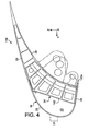
- flaps of leading edge 116, 216, 316 are respectively shown in second, third and fourth preferred embodiments of the present invention. These flaps 116, 216, 316 also extend for example over substantially the entire length of the wing 4 concerned, in the longitudinal direction of leading edge X.
- the ribs 34, 40 have a front portion 142 which takes the form of a not curved surface, but substantially flat and which extends parallel to the direction X. As visible on the figure 4 , the aforementioned surface extends upwardly towards the rear. As such, although it does not have notch, it is noted that the front portion 142 is still located sufficiently far away from the front zone 24, to allow a significant absorption of shock energy during the In addition, it is noted that the removal of the notch provides increased rigidity compared to that presented by the force introduction ribs of the first preferred embodiment.
- the flap 216 according to the third preferred embodiment of the present invention. Only the multicellular rear structure 21 provided at the rear portion 19 of the flap 216 differs from that disclosed in the first preferred embodiment.
- the multicellular rear-structure 21 has an extrados portion 23 and a rear coating 28 identical or similar to those described for the flap 16, but the set of boxes 25 is replaced by a honeycomb core 225 , made for example of synthetic material.
- the portion 23 and the coating 28, preferably made of carbon impregnated synthetic resin, together with the core 225 form a sandwich-type structure that increases the rigidity of the rear portion 19 of the shutter 216, and substantially reduce the overall mass of the latter.
- this third preferred embodiment of the present invention is particularly advantageous for large-scale shutters.
- the front of the honeycomb core 225 may advantageously be in plane contact with the portion upper rear 46 of each of the force introduction ribs 34, 40.
- an armature 227 between the upper rear portion 46 of each of the ribs 34, 40, and the honeycomb core 225. In this configuration, the armature 227 then extends according to the X direction over the full span of component 216.
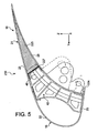
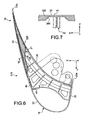
- a honeycomb core 325 located between the extrados portion 23 and the rear coating 28, and which has the particularity of having 360 passages oriented in the transverse direction Y and spaced in the direction X, as this is seen on the figure 7 (only one passage 360 being shown in this figure).
- Each passage 360 allows an associated rib 34, 40 to extend towards the rear of the flap 316 through the same core 325, for example near the trailing edge 23a.
- the core 325 can also be extended forward with respect to the solution of the third preferred embodiment.
- an upper part of the honeycomb core 325 extends for example up to near the junction between the extrados parts 22, 23.
- the core 325 covers most of the portion extrados 23 of the multicellular rear-structure 21.
- This fourth preferred embodiment offers the advantage of combining the intrinsic rigidity of a sandwich-type structure with the presence of large force introduction ribs, capable of introducing significant dynamic forces compared to the ribs of the sandwich.
- first two preferred embodiments By way of indication, this combination not only makes it possible to optimize the strength and the overall mass of a large flap, but also allows the widening of the depth of the notch provided for on the front portion 42 of each of the ribs. effort introduction 34, 40.
Landscapes
- Engineering & Computer Science (AREA)
- Aviation & Aerospace Engineering (AREA)
- Details Or Accessories Of Spraying Plant Or Apparatus (AREA)
- Wind Motors (AREA)
- Structures Of Non-Positive Displacement Pumps (AREA)
- Vibration Dampers (AREA)
- Specific Sealing Or Ventilating Devices For Doors And Windows (AREA)
- Air Filters, Heat-Exchange Apparatuses, And Housings Of Air-Conditioning Units (AREA)
- Aiming, Guidance, Guns With A Light Source, Armor, Camouflage, And Targets (AREA)
Claims (15)
- Bewegliche Vorderkantenklappe (16, 116, 216, 316) für einen Hauptflügel der Tragfläche eines Luftfahrzeugs, wobei die Klappe eine aerodynamische Verkleidung (18) umfasst, die eine frontale Zone (24) aufweist, einen Oberseitenabschnitt (22) sowie einen Unterseitenabschnitt (20), wobei die Klappe ferner eine Mehrzahl von Krafteinleitungsrippen (34, 40) umfasst, die entlang einer Längsrichtung der Vorderkante (X) beabstandet sind und jeweils über einen oberen Teil (44) und einen unteren Teil (50) verfügen, die mit dem Oberseiten- bzw. Unterseitenabschnitt (22, 20) der aerodynamischen Verkleidung (18) verbunden sind, dadurch gekennzeichnet, dass jede dieser Rippen (34, 40) ferner einen vorderen Teil (42, 142) aufweist, der von der frontalen Zone (24) der aerodynamischen Verkleidung (18) beabstandet ist.
- Bewegliche Vorderkantenklappe (16, 116, 216, 316) nach Anspruch 1, dadurch gekennzeichnet, dass sie eine vielzellige Rückstruktur (21) umfasst, die in Kontakt mit und an der Rückseite der Krafteinleitungsrippen (34, 40) angeordnet ist.
- Bewegliche Vorderkantenklappe (16, 116, 216, 316) nach Anspruch 2, dadurch gekennzeichnet, dass die vielzellige Rückstruktur (21) einen Oberseitenabschnitt (23) umfasst, der am Oberseitenabschnitt (22) der aerodynamischen Verkleidung (18) angebracht ist, sowie eine rückseitige Verkleidung (28), die eine rückseitige Verkleidung der Klappe bildet und an einem rückseitigen Teil (48) jeder der Krafteinleitungsrippen (34, 40) angebracht ist, wobei sich die rückseitige Verkleidung (28) bis zu einer Hinterkante (20a) des Oberseitenabschnitts (20) der vielzelligen Rückstruktur (21) erstreckt.
- Bewegliche Vorderkantenklappe (16, 116, 216, 316) nach Anspruch 3, dadurch gekennzeichnet, dass die zwei Oberseitenabschnitte (22, 23) am oberen Teil (44) jeder der Krafteinleitungsrippen (34,40) angebracht sind.
- Bewegliche Vorderkantenklappe (16, 116) nach Anspruch 3 oder nach Anspruch 4, dadurch gekennzeichnet, dass die vielzellige Rückstruktur (21) ferner eine Gruppe von Kästen (25) umfasst, die zwischen der rückseitigen Verkleidung (28) und dem Oberseitenabschnitt (23) der vielzelligen Struktur (21) angeordnet ist, wobei die Gruppe von Kästen (25) an der Rückseite eines rückseitigen oberen Teils (46) jeder der Krafteinleitungsrippen (34, 40) angeordnet ist.
- Bewegliche Vorderkantenklappe (16, 116) nach Anspruch 5, dadurch gekennzeichnet, dass die vielzellige Rückstruktur (21) in einem Stück durch Vakuumspritzgießen hergestellt ist.
- Bewegliche Vorderkantenklappe (216, 316) nach Anspruch 3 oder nach Anspruch 4, dadurch gekennzeichnet, dass die vielzellige Rückstruktur (21) ferner eine wabenförmige Seele (225, 325) umfasst, die zwischen der rückseitigen Verkleidung (28) und dem Oberseitenabschnitt (23) der vielzelligen Struktur (21) angeordnet ist.
- Bewegliche Vorderkantenklappe (16, 116, 216, 316) nach einem der Ansprüche 3 bis 7, dadurch gekennzeichnet, dass sie ferner eine untere Versteifung (56) umfasst, die sich entlang der Längsrichtung der Vorderkante (X) erstreckt, wobei die untere Versteifung (56) eine Verbindung zwischen dem Unterseitenabschnitt (20) der aerodynamischen Verkleidung (18) und der rückseitigen Verkleidung (28) der vielzelligen Rückstruktur (21) gewährleistet.
- Bewegliche Vorderkantenklappe (16, 116, 216, 316) nach Anspruch 8, dadurch gekennzeichnet, dass die untere Versteifung (56) einen L-förmigen Querschnitt aufweist, wobei der rückseitige Teil (48) jeder der Krafteinleitungsrippen (34, 40) auf dem seitlichen Arm des L ruht, und der Unterseitenabschnitt (20) der aerodynamischen Verkleidung (18) auf der Basis dieses L ruht.
- Bewegliche Vorderkantenklappe (16, 116, 216, 316) nach einem der vorhergehenden Ansprüche, dadurch gekennzeichnet, dass sie ferner eine obere Versteifung (58) umfasst, die sich entlang der Längsrichtung der Vorderkante (X) erstreckt, wobei die obere Versteifung (58) in Kontakt ist mit dem vorderen Teil (42) und dem oberen Teil (44) jeder der Krafteinleitungsrippen (34, 40).
- Bewegliche Vorderkantenklappe (16, 116, 216, 316) nach einem der vorhergehenden Ansprüche, dadurch gekennzeichnet, dass sie zwei Endrippen (32) umfasst.
- Bewegliche Vorderkantenklappe (16, 116, 216, 316) nach einem der vorhergehenden Ansprüche, dadurch gekennzeichnet, dass der vordere Teil (42) jeder der Krafteinleitungsrippen (34, 40) eine Einbuchtung aufweist.
- Bewegliche Vorderkantenklappe (16, 116, 216, 316) nach einem der vorhergehenden Ansprüche in Kombination mit den Ansprüchen 9 und 10, dadurch gekennzeichnet, dass in einem Querschnitt entlang einer beliebigen Ebene orthogonal zu der Richtung (X) bei Betrachtung eines Punkts (C) entsprechend einem vorderen Auflagepunkt der Verkleidung (18) auf der oberen Versteifung (58), eines Punkts (D) entsprechend einem vorderen Auflagepunkt der Verkleidung (18) auf dem unteren Teil (50) jeder Krafteinleitungsrippe (34, 40), eines Geradensegments (CD) und einer Mitte (E) desselben, einer Gerade (d), die durch diese Mitte (E) verläuft und parallel ist zu einer Sehne (26) des Tragflächenelements, eines Punkts (F), der einen Schnittpunkt zwischen der Gerade (d) und der frontalen Zone (24) darstellt, eines Punkts (G) entsprechend einem Schnittpunkt zwischen dieser Gerade (d) und dem vorderen Teil (42) der Rippe (40), eines Abstands (X1) entsprechend der Länge eines Geradensegments (FG), und eines Abstands (X2) entsprechend der Länge eines Geradensegments (EF), der Abstand (X1) dann zwischen eineinhalb Mal und zwei Mal der Länge (X2) enthalten ist.
- Bewegliche Vorderkantenklappe (16, 116, 216, 316) nach einem der vorhergehenden Ansprüche, dadurch gekennzeichnet, dass sie derart gestaltet ist, dass zwischen zwei beliebigen Krafteinleitungsrippen (34, 40), die in der Richtung (X) direkt aufeinander folgen, die aerodynamische Verkleidung (18) sich frei über die vorderen Teile (42) dieser Rippen hinaus verformen kann.
- Bewegliche Vorderkantenklappe (16, 116, 216, 316) nach einem der vorhergehenden Ansprüche, dadurch gekennzeichnet, dass die aerodynamische Verkleidung (18) mit Hilfe eines duktilen Materials hergestellt ist.
Applications Claiming Priority (2)
| Application Number | Priority Date | Filing Date | Title |
|---|---|---|---|
| BE2004/0342A BE1016117A3 (fr) | 2004-07-09 | 2004-07-09 | Volet mobile de bord d'attaque d'une aile principale de la voilure d'un aeronef. |
| PCT/EP2005/053253 WO2006010699A1 (fr) | 2004-07-09 | 2005-07-07 | Volet mobile de bord d'attaque d'une aile principale de la voilure d'un aeronef |
Publications (2)
| Publication Number | Publication Date |
|---|---|
| EP1768898A1 EP1768898A1 (de) | 2007-04-04 |
| EP1768898B1 true EP1768898B1 (de) | 2008-06-18 |
Family
ID=34923685
Family Applications (1)
| Application Number | Title | Priority Date | Filing Date |
|---|---|---|---|
| EP05761099A Expired - Lifetime EP1768898B1 (de) | 2004-07-09 | 2005-07-07 | Bewegliche vorderkantenklappe für einen hauptflügel der tragflächen eines flugzeugs |
Country Status (6)
| Country | Link |
|---|---|
| EP (1) | EP1768898B1 (de) |
| AT (1) | ATE398570T1 (de) |
| BE (1) | BE1016117A3 (de) |
| DE (1) | DE602005007608D1 (de) |
| ES (1) | ES2308518T3 (de) |
| WO (1) | WO2006010699A1 (de) |
Cited By (1)
| Publication number | Priority date | Publication date | Assignee | Title |
|---|---|---|---|---|
| US11383821B2 (en) | 2019-03-22 | 2022-07-12 | Airbus Operations Gmbh | Wing leading-edge device and a wing having such a wing leading-edge device |
Families Citing this family (6)
| Publication number | Priority date | Publication date | Assignee | Title |
|---|---|---|---|---|
| DE602006013236D1 (de) * | 2005-08-25 | 2010-05-12 | Gkn Aerospace Services Ltd | Vorflügel für eine Flugzeugtragfläche |
| US7753313B1 (en) * | 2006-09-19 | 2010-07-13 | The Boeing Company | Composite wing slat for aircraft |
| JP6782533B2 (ja) * | 2015-08-26 | 2020-11-11 | 三菱航空機株式会社 | 航空機の前縁構造体、航空機の翼及び航空機 |
| EP4140877B1 (de) * | 2019-01-18 | 2025-07-02 | Asco Industries NV | Vorflügel für einen flugzeugflügel, verfahren zur herstellung solch eines vorflügels |
| US11453477B2 (en) * | 2019-02-28 | 2022-09-27 | Airbus Operations Gmbh | Wing leading edge device and a wing having such a wing leading edge device |
| EP4147975B1 (de) * | 2021-09-08 | 2025-11-26 | Airbus Operations GmbH | Strömungskörper mit zwei in sehnenrichtung beabstandeten heizvorrichtungen |
Family Cites Families (5)
| Publication number | Priority date | Publication date | Assignee | Title |
|---|---|---|---|---|
| GB2324351A (en) * | 1997-04-18 | 1998-10-21 | British Aerospace | Reducing drag in aircraft wing assembly |
| BE1012781A3 (fr) * | 1999-07-09 | 2001-03-06 | Sonaca Sa | Procede d'assemblage d'un panneau souple sur une structure ouverte et installation pour la mise en oeuvre de ce procede. |
| ES2197727B1 (es) | 2000-07-27 | 2005-04-01 | Construcciones Aeronauticas, S.A. | Borde de ataque de superficies sustentadoras de aeronaves. |
| BE1014570A4 (fr) * | 2002-01-11 | 2004-01-13 | Sonaca Sa | Procede de fabrication d'une structure cannelee et structure obtenue par ce procede. |
| JP4057331B2 (ja) * | 2002-04-05 | 2008-03-05 | 日本飛行機株式会社 | 衝撃耐久構造体 |
-
2004
- 2004-07-09 BE BE2004/0342A patent/BE1016117A3/fr not_active IP Right Cessation
-
2005
- 2005-07-07 EP EP05761099A patent/EP1768898B1/de not_active Expired - Lifetime
- 2005-07-07 ES ES05761099T patent/ES2308518T3/es not_active Expired - Lifetime
- 2005-07-07 DE DE602005007608T patent/DE602005007608D1/de not_active Expired - Lifetime
- 2005-07-07 AT AT05761099T patent/ATE398570T1/de active
- 2005-07-07 WO PCT/EP2005/053253 patent/WO2006010699A1/fr not_active Ceased
Cited By (1)
| Publication number | Priority date | Publication date | Assignee | Title |
|---|---|---|---|---|
| US11383821B2 (en) | 2019-03-22 | 2022-07-12 | Airbus Operations Gmbh | Wing leading-edge device and a wing having such a wing leading-edge device |
Also Published As
| Publication number | Publication date |
|---|---|
| ES2308518T3 (es) | 2008-12-01 |
| EP1768898A1 (de) | 2007-04-04 |
| BE1016117A3 (fr) | 2006-03-07 |
| WO2006010699A1 (fr) | 2006-02-02 |
| DE602005007608D1 (de) | 2008-07-31 |
| ATE398570T1 (de) | 2008-07-15 |
Similar Documents
| Publication | Publication Date | Title |
|---|---|---|
| BE1015867A3 (fr) | Ensemble de bord d'attaque d'un element de voilure d'aeronef et element de voilure equipee d'au moins un tel ensemble. | |
| EP0346210B1 (de) | Faserverstärktes Spant, insbesondere eines Luftfahrzeugrumpfs, und sein Herstellungsverfahren | |
| EP2540620B1 (de) | Rotorblatt und Luftfahrzeug, ausgestattet mit einem derartigen Rotorblatt | |
| EP2706011B1 (de) | Laterale Antriebseinheit für Luftfahrzeug mit einem Triebwerksaufhängebogen | |
| CA2632913C (fr) | Procede de fabrication d'un fuselage d'aeronef en materiau composite | |
| EP1813527B1 (de) | Aufprallschutzstruktur aus Verbundwerkstoff und mit seitlicher Führung für Luftfahrzeuge | |
| FR2909359A1 (fr) | Avion a reacteurs disposes a l'arriere | |
| EP2242683B1 (de) | Monolothische, selbstversteifende und schwenkbare verbundplatte, insbesondere für ein mobiles flugzeugbauteil | |
| EP2653377B1 (de) | Aerodynamische Tragfläche eines Luftfahrzeugs, und mit einer solchen aerodynamischen Tragfläche ausgestattetes Luftfahrzeug | |
| CA2825876A1 (fr) | Aeronef a impact environnemental reduit | |
| WO2011007074A1 (fr) | Structure de bord d'attaque notamment pour entree d'air de nacelle de moteur d'aeronef | |
| FR3073824A1 (fr) | Ensemble pour aeronef comprenant une structure primaire de mat d'accrochage fixee a un caisson de voilure par des attaches partiellement enterrees dans la structure primaire | |
| EP1768898B1 (de) | Bewegliche vorderkantenklappe für einen hauptflügel der tragflächen eines flugzeugs | |
| FR2964426A1 (fr) | Aube mobile en materiau composite | |
| EP2595879B1 (de) | Verfahren und vorrichtung zur seitlichen stabilisierung eines flugzeugs | |
| FR3115016A1 (fr) | Hélice carénée d’un aéronef et aéronef | |
| EP3674205B1 (de) | Vorflügel mit optimierter struktur | |
| CA2757910C (fr) | Procede de fabrication d'un panneau structurant composite de bord de fuite pour un element d'un aeronef | |
| EP3287363B1 (de) | Tragflächenerweiterung für einen flügel eines luftfahrzeugs | |
| EP0776823A1 (de) | Rotorblätter eines Drehflügelflugzeuges mit Blitzschutzschild | |
| FR3069527A1 (fr) | Structure primaire a conception amelioree pour mat d'accrochage de moteur d'aeronef | |
| FR3020338A1 (fr) | Partie arriere d'aeronef pourvue d'une structure de support des moteurs de forme optimisee | |
| EP4463374A1 (de) | Bewegliche vorderkantenklappe mit mehreren kraftströmungswegen | |
| FR3154462A1 (fr) | Aube a calage variable pour une helice de turbomachine d’aeronef | |
| BE335501A (de) |
Legal Events
| Date | Code | Title | Description |
|---|---|---|---|
| PUAI | Public reference made under article 153(3) epc to a published international application that has entered the european phase |
Free format text: ORIGINAL CODE: 0009012 |
|
| 17P | Request for examination filed |
Effective date: 20061220 |
|
| AK | Designated contracting states |
Kind code of ref document: A1 Designated state(s): AT BE BG CH CY CZ DE DK EE ES FI FR GB GR HU IE IS IT LI LT LU LV MC NL PL PT RO SE SI SK TR |
|
| DAX | Request for extension of the european patent (deleted) | ||
| GRAP | Despatch of communication of intention to grant a patent |
Free format text: ORIGINAL CODE: EPIDOSNIGR1 |
|
| GRAS | Grant fee paid |
Free format text: ORIGINAL CODE: EPIDOSNIGR3 |
|
| GRAA | (expected) grant |
Free format text: ORIGINAL CODE: 0009210 |
|
| AK | Designated contracting states |
Kind code of ref document: B1 Designated state(s): AT BE BG CH CY CZ DE DK EE ES FI FR GB GR HU IE IS IT LI LT LU LV MC NL PL PT RO SE SI SK TR |
|
| REG | Reference to a national code |
Ref country code: GB Ref legal event code: FG4D Free format text: NOT ENGLISH |
|
| REF | Corresponds to: |
Ref document number: 602005007608 Country of ref document: DE Date of ref document: 20080731 Kind code of ref document: P |
|
| REG | Reference to a national code |
Ref country code: CH Ref legal event code: EP |
|
| REG | Reference to a national code |
Ref country code: IE Ref legal event code: FG4D Free format text: LANGUAGE OF EP DOCUMENT: FRENCH |
|
| REG | Reference to a national code |
Ref country code: SE Ref legal event code: TRGR |
|
| PG25 | Lapsed in a contracting state [announced via postgrant information from national office to epo] |
Ref country code: FI Free format text: LAPSE BECAUSE OF FAILURE TO SUBMIT A TRANSLATION OF THE DESCRIPTION OR TO PAY THE FEE WITHIN THE PRESCRIBED TIME-LIMIT Effective date: 20080618 Ref country code: SI Free format text: LAPSE BECAUSE OF FAILURE TO SUBMIT A TRANSLATION OF THE DESCRIPTION OR TO PAY THE FEE WITHIN THE PRESCRIBED TIME-LIMIT Effective date: 20080618 |
|
| PG25 | Lapsed in a contracting state [announced via postgrant information from national office to epo] |
Ref country code: LV Free format text: LAPSE BECAUSE OF FAILURE TO SUBMIT A TRANSLATION OF THE DESCRIPTION OR TO PAY THE FEE WITHIN THE PRESCRIBED TIME-LIMIT Effective date: 20080618 Ref country code: PL Free format text: LAPSE BECAUSE OF FAILURE TO SUBMIT A TRANSLATION OF THE DESCRIPTION OR TO PAY THE FEE WITHIN THE PRESCRIBED TIME-LIMIT Effective date: 20080618 |
|
| REG | Reference to a national code |
Ref country code: ES Ref legal event code: FG2A Ref document number: 2308518 Country of ref document: ES Kind code of ref document: T3 |
|
| PG25 | Lapsed in a contracting state [announced via postgrant information from national office to epo] |
Ref country code: IS Free format text: LAPSE BECAUSE OF FAILURE TO SUBMIT A TRANSLATION OF THE DESCRIPTION OR TO PAY THE FEE WITHIN THE PRESCRIBED TIME-LIMIT Effective date: 20081018 Ref country code: CZ Free format text: LAPSE BECAUSE OF FAILURE TO SUBMIT A TRANSLATION OF THE DESCRIPTION OR TO PAY THE FEE WITHIN THE PRESCRIBED TIME-LIMIT Effective date: 20080618 Ref country code: LT Free format text: LAPSE BECAUSE OF FAILURE TO SUBMIT A TRANSLATION OF THE DESCRIPTION OR TO PAY THE FEE WITHIN THE PRESCRIBED TIME-LIMIT Effective date: 20080618 |
|
| REG | Reference to a national code |
Ref country code: IE Ref legal event code: FD4D |
|
| PG25 | Lapsed in a contracting state [announced via postgrant information from national office to epo] |
Ref country code: RO Free format text: LAPSE BECAUSE OF FAILURE TO SUBMIT A TRANSLATION OF THE DESCRIPTION OR TO PAY THE FEE WITHIN THE PRESCRIBED TIME-LIMIT Effective date: 20080618 Ref country code: PT Free format text: LAPSE BECAUSE OF FAILURE TO SUBMIT A TRANSLATION OF THE DESCRIPTION OR TO PAY THE FEE WITHIN THE PRESCRIBED TIME-LIMIT Effective date: 20081118 Ref country code: SK Free format text: LAPSE BECAUSE OF FAILURE TO SUBMIT A TRANSLATION OF THE DESCRIPTION OR TO PAY THE FEE WITHIN THE PRESCRIBED TIME-LIMIT Effective date: 20080618 |
|
| PG25 | Lapsed in a contracting state [announced via postgrant information from national office to epo] |
Ref country code: MC Free format text: LAPSE BECAUSE OF NON-PAYMENT OF DUE FEES Effective date: 20080731 |
|
| NLV4 | Nl: lapsed or anulled due to non-payment of the annual fee |
Effective date: 20090201 |
|
| PLBE | No opposition filed within time limit |
Free format text: ORIGINAL CODE: 0009261 |
|
| STAA | Information on the status of an ep patent application or granted ep patent |
Free format text: STATUS: NO OPPOSITION FILED WITHIN TIME LIMIT |
|
| PG25 | Lapsed in a contracting state [announced via postgrant information from national office to epo] |
Ref country code: DK Free format text: LAPSE BECAUSE OF FAILURE TO SUBMIT A TRANSLATION OF THE DESCRIPTION OR TO PAY THE FEE WITHIN THE PRESCRIBED TIME-LIMIT Effective date: 20080618 Ref country code: BG Free format text: LAPSE BECAUSE OF FAILURE TO SUBMIT A TRANSLATION OF THE DESCRIPTION OR TO PAY THE FEE WITHIN THE PRESCRIBED TIME-LIMIT Effective date: 20080918 Ref country code: EE Free format text: LAPSE BECAUSE OF FAILURE TO SUBMIT A TRANSLATION OF THE DESCRIPTION OR TO PAY THE FEE WITHIN THE PRESCRIBED TIME-LIMIT Effective date: 20080618 |
|
| 26N | No opposition filed |
Effective date: 20090319 |
|
| NLXE | Nl: other communications concerning ep-patents (part 3 heading xe) |
Free format text: A REQUEST FOR RESTORATION TO THE PRIOR STATE (ARTICLE 23 OF THE PATENTS ACT 1995) HAS BEEN FILED ON 20090410 |
|
| NLXE | Nl: other communications concerning ep-patents (part 3 heading xe) |
Free format text: THE REQUEST FOR RESTORATION TO THE PRIOR STATE, AS PROVIDED FOR IN ARTICLE 23 OF THE PATENTS ACT 1995 (SEE PUBLICATION IN HEADING XE OF THE PATENT BULLETIN OF 20090602), HAS BEEN GRANTED; THE RESTORATION OF THE PATENT HAS BEEN ENTERED IN THE PATENT REGISTER. |
|
| PG25 | Lapsed in a contracting state [announced via postgrant information from national office to epo] |
Ref country code: BE Free format text: LAPSE BECAUSE OF NON-PAYMENT OF DUE FEES Effective date: 20080731 Ref country code: CY Free format text: LAPSE BECAUSE OF FAILURE TO SUBMIT A TRANSLATION OF THE DESCRIPTION OR TO PAY THE FEE WITHIN THE PRESCRIBED TIME-LIMIT Effective date: 20080618 Ref country code: LU Free format text: LAPSE BECAUSE OF NON-PAYMENT OF DUE FEES Effective date: 20080707 Ref country code: HU Free format text: LAPSE BECAUSE OF FAILURE TO SUBMIT A TRANSLATION OF THE DESCRIPTION OR TO PAY THE FEE WITHIN THE PRESCRIBED TIME-LIMIT Effective date: 20081219 |
|
| PG25 | Lapsed in a contracting state [announced via postgrant information from national office to epo] |
Ref country code: TR Free format text: LAPSE BECAUSE OF FAILURE TO SUBMIT A TRANSLATION OF THE DESCRIPTION OR TO PAY THE FEE WITHIN THE PRESCRIBED TIME-LIMIT Effective date: 20080618 |
|
| PG25 | Lapsed in a contracting state [announced via postgrant information from national office to epo] |
Ref country code: GR Free format text: LAPSE BECAUSE OF FAILURE TO SUBMIT A TRANSLATION OF THE DESCRIPTION OR TO PAY THE FEE WITHIN THE PRESCRIBED TIME-LIMIT Effective date: 20080919 |
|
| REG | Reference to a national code |
Ref country code: FR Ref legal event code: PLFP Year of fee payment: 12 |
|
| REG | Reference to a national code |
Ref country code: FR Ref legal event code: PLFP Year of fee payment: 13 |
|
| REG | Reference to a national code |
Ref country code: FR Ref legal event code: PLFP Year of fee payment: 14 |
|
| PGFP | Annual fee paid to national office [announced via postgrant information from national office to epo] |
Ref country code: AT Payment date: 20180620 Year of fee payment: 14 |
|
| REG | Reference to a national code |
Ref country code: CH Ref legal event code: PL |
|
| REG | Reference to a national code |
Ref country code: AT Ref legal event code: MM01 Ref document number: 398570 Country of ref document: AT Kind code of ref document: T Effective date: 20190707 |
|
| PG25 | Lapsed in a contracting state [announced via postgrant information from national office to epo] |
Ref country code: AT Free format text: LAPSE BECAUSE OF NON-PAYMENT OF DUE FEES Effective date: 20190707 |
|
| PG25 | Lapsed in a contracting state [announced via postgrant information from national office to epo] |
Ref country code: CH Free format text: LAPSE BECAUSE OF NON-PAYMENT OF DUE FEES Effective date: 20190731 Ref country code: LI Free format text: LAPSE BECAUSE OF NON-PAYMENT OF DUE FEES Effective date: 20190731 |
|
| PGFP | Annual fee paid to national office [announced via postgrant information from national office to epo] |
Ref country code: NL Payment date: 20240729 Year of fee payment: 20 |
|
| PGFP | Annual fee paid to national office [announced via postgrant information from national office to epo] |
Ref country code: DE Payment date: 20240729 Year of fee payment: 20 Ref country code: IE Payment date: 20240729 Year of fee payment: 20 |
|
| PGFP | Annual fee paid to national office [announced via postgrant information from national office to epo] |
Ref country code: GB Payment date: 20240730 Year of fee payment: 20 |
|
| PGFP | Annual fee paid to national office [announced via postgrant information from national office to epo] |
Ref country code: FR Payment date: 20240730 Year of fee payment: 20 |
|
| PGFP | Annual fee paid to national office [announced via postgrant information from national office to epo] |
Ref country code: ES Payment date: 20240911 Year of fee payment: 20 |
|
| PGFP | Annual fee paid to national office [announced via postgrant information from national office to epo] |
Ref country code: SE Payment date: 20240731 Year of fee payment: 20 Ref country code: IT Payment date: 20240729 Year of fee payment: 20 |
|
| REG | Reference to a national code |
Ref country code: DE Ref legal event code: R071 Ref document number: 602005007608 Country of ref document: DE |
|
| REG | Reference to a national code |
Ref country code: NL Ref legal event code: MK Effective date: 20250706 |
|
| REG | Reference to a national code |
Ref country code: ES Ref legal event code: FD2A Effective date: 20250728 |
|
| REG | Reference to a national code |
Ref country code: GB Ref legal event code: PE20 Expiry date: 20250706 |
|
| REG | Reference to a national code |
Ref country code: IE Ref legal event code: MK9A |
|
| REG | Reference to a national code |
Ref country code: SE Ref legal event code: EUG |
|
| PG25 | Lapsed in a contracting state [announced via postgrant information from national office to epo] |
Ref country code: ES Free format text: LAPSE BECAUSE OF EXPIRATION OF PROTECTION Effective date: 20250708 |
|
| PG25 | Lapsed in a contracting state [announced via postgrant information from national office to epo] |
Ref country code: IE Free format text: LAPSE BECAUSE OF EXPIRATION OF PROTECTION Effective date: 20250707 |