EP3674149A1 - Wischblattadapter mit integrierten fluidleitungen - Google Patents
Wischblattadapter mit integrierten fluidleitungen Download PDFInfo
- Publication number
- EP3674149A1 EP3674149A1 EP19218760.7A EP19218760A EP3674149A1 EP 3674149 A1 EP3674149 A1 EP 3674149A1 EP 19218760 A EP19218760 A EP 19218760A EP 3674149 A1 EP3674149 A1 EP 3674149A1
- Authority
- EP
- European Patent Office
- Prior art keywords
- wiper blade
- blade adapter
- fluid lines
- wiper
- seal cover
- Prior art date
- Legal status (The legal status is an assumption and is not a legal conclusion. Google has not performed a legal analysis and makes no representation as to the accuracy of the status listed.)
- Granted
Links
- 239000012530 fluid Substances 0.000 title claims abstract description 41
- 238000007789 sealing Methods 0.000 claims abstract description 14
- 238000002347 injection Methods 0.000 claims abstract description 6
- 239000007924 injection Substances 0.000 claims abstract description 6
- 239000004033 plastic Substances 0.000 claims abstract description 5
- 239000000463 material Substances 0.000 claims description 2
- 229920002725 thermoplastic elastomer Polymers 0.000 claims description 2
- 239000007788 liquid Substances 0.000 description 3
- 238000004140 cleaning Methods 0.000 description 2
- 238000001746 injection moulding Methods 0.000 description 2
- 238000004519 manufacturing process Methods 0.000 description 2
- 238000005406 washing Methods 0.000 description 2
- 238000003466 welding Methods 0.000 description 2
- 238000011161 development Methods 0.000 description 1
- 230000018109 developmental process Effects 0.000 description 1
- 238000009826 distribution Methods 0.000 description 1
- 238000003780 insertion Methods 0.000 description 1
- 230000037431 insertion Effects 0.000 description 1
- 238000000034 method Methods 0.000 description 1
- 239000002991 molded plastic Substances 0.000 description 1
- 238000004023 plastic welding Methods 0.000 description 1
- 238000012545 processing Methods 0.000 description 1
- 239000007921 spray Substances 0.000 description 1
- 238000012546 transfer Methods 0.000 description 1
Images

Classifications
-
- B—PERFORMING OPERATIONS; TRANSPORTING
- B60—VEHICLES IN GENERAL
- B60S—SERVICING, CLEANING, REPAIRING, SUPPORTING, LIFTING, OR MANOEUVRING OF VEHICLES, NOT OTHERWISE PROVIDED FOR
- B60S1/00—Cleaning of vehicles
- B60S1/02—Cleaning windscreens, windows or optical devices
- B60S1/04—Wipers or the like, e.g. scrapers
- B60S1/32—Wipers or the like, e.g. scrapers characterised by constructional features of wiper blade arms or blades
- B60S1/40—Connections between blades and arms
-
- B—PERFORMING OPERATIONS; TRANSPORTING
- B60—VEHICLES IN GENERAL
- B60S—SERVICING, CLEANING, REPAIRING, SUPPORTING, LIFTING, OR MANOEUVRING OF VEHICLES, NOT OTHERWISE PROVIDED FOR
- B60S1/00—Cleaning of vehicles
- B60S1/02—Cleaning windscreens, windows or optical devices
- B60S1/04—Wipers or the like, e.g. scrapers
- B60S1/32—Wipers or the like, e.g. scrapers characterised by constructional features of wiper blade arms or blades
- B60S1/38—Wiper blades
- B60S1/3848—Flat-type wiper blade, i.e. without harness
- B60S1/3849—Connectors therefor; Connection to wiper arm; Attached to blade
- B60S1/3862—Transport of liquid there through
-
- B—PERFORMING OPERATIONS; TRANSPORTING
- B60—VEHICLES IN GENERAL
- B60S—SERVICING, CLEANING, REPAIRING, SUPPORTING, LIFTING, OR MANOEUVRING OF VEHICLES, NOT OTHERWISE PROVIDED FOR
- B60S1/00—Cleaning of vehicles
- B60S1/02—Cleaning windscreens, windows or optical devices
- B60S1/04—Wipers or the like, e.g. scrapers
- B60S1/32—Wipers or the like, e.g. scrapers characterised by constructional features of wiper blade arms or blades
- B60S1/38—Wiper blades
- B60S1/3806—Means, or measures taken, for influencing the aerodynamic quality of the wiper blades
- B60S1/381—Spoilers mounted on the squeegee or on the vertebra
-
- B—PERFORMING OPERATIONS; TRANSPORTING
- B60—VEHICLES IN GENERAL
- B60S—SERVICING, CLEANING, REPAIRING, SUPPORTING, LIFTING, OR MANOEUVRING OF VEHICLES, NOT OTHERWISE PROVIDED FOR
- B60S1/00—Cleaning of vehicles
- B60S1/02—Cleaning windscreens, windows or optical devices
- B60S1/46—Cleaning windscreens, windows or optical devices using liquid; Windscreen washers
- B60S1/48—Liquid supply therefor
- B60S1/52—Arrangement of nozzles; Liquid spreading means
- B60S1/522—Arrangement of nozzles; Liquid spreading means moving liquid spreading means, e.g. arranged in wiper arms
- B60S1/524—Arrangement of nozzles; Liquid spreading means moving liquid spreading means, e.g. arranged in wiper arms arranged in wiper blades
Definitions
- the invention relates to a wiper blade adapter with integrated fluid lines according to the preamble of the independent claim.
- a wiper blade is connected to a wiper arm via a wiper blade adapter to enable the wiper blade to be mounted on the vehicle and changed.
- the wiper blade adapter serves to transfer the lateral managers from the wiper arm to the wiper blade during the wiping movement.
- a wiper blade adapter often enables a rotary movement so that the wiper blade can adapt to the inclination and curvature of the window during the wiping movement.
- Two-part designs are known in which the wiper blade adapter comprises a swivel joint, but also designs in which the connection to the wiper arm takes place on an axis which enables rotation and can be releasably placed on the receiving elements of the wiper arm.
- wiper blades are also known which have nozzles for applying a cleaning fluid to a window and in which fluid feed lines are led to the wiper arm through the wiper blade adapter and can be detachably connected to the wiper blade adapter.
- the supply of the nozzles in the wiper blade for example in the end regions of the wiper blade, requires a distributor fluid line along the wiper blade.
- the adapter has horizontal outlet fluid lines which are connected to such distributor fluid lines, for example formed in a spoiler.
- a fluid line is fed from the wiper arm in the upper area of the wiper blade adapter. For this there is an essentially horizontal inflow fluid line with connections in the wiper blade adapter.
- the wiper blade adapter is now produced as one component by plastic injection molding and the fluid lines within the wiper blade adapter are integrated into this plastic injection molded part connecting channels must be provided between these lower outlet fluid lines and the upper inlet fluid line or lines.
- cores are provided on the tool, which have to be pulled out during demolding.
- connection channels on one side, either below or above, on which they are connected to the outlet fluid lines or inlet fluid lines, are open after manufacture and have to be sealed.
- connection device for connecting a wiper blade to a wiper arm, which has at least means for a fixed connection to the wiper blade and connection means for the wiper arm. Furthermore, the connecting device comprises a line for a washing liquid with a plurality of spray openings for applying washing liquid to the pane.
- a connection channel is described between a supply line and a distribution line, which has a sleeve at its lower end. This arises from the fact that the opening of the connecting channel has to be sealed during production, for example by ultrasonic welding or the insertion of a sealing ball.
- a connecting element for a wiper blade is known that is also a hydraulic connecting element.
- the connecting element has an internal line in order to conduct the liquid from an inlet arranged horizontally at the top to a lower distributor line.
- the connecting element is divided in the plane of these internal lines, which are arranged vertically, in order to be able to produce it.
- the parts can be joined by ultrasonic welding or joint overmolding.
- the wiper blade adapter with the features of main claim 1 has the advantage that the seal cover covers all openings of the connecting channels as a component and, if used, seals all in one assembly step.
- openings in the connecting channels are formed which are not desired, but cannot be avoided because essentially, for example on an upper side and apart from a slight angular deviation, inlet fluid lines aligned parallel to a window surface are connected to distributor fluid lines which are also aligned but are located further down have to.
- the connection channels required for this must be formed in the injection molding tool with the aid of a core, which is pulled out to one side when the Demolding leaves an undesirable opening.
- the sealing elements advantageously consist of sealing plugs, in particular of molded thermoplastic elastomer materials. A particularly reliable seal can be achieved in this way.
- the seal cover is arranged on an upper side. It is also conceivable to use a seal cover on the underside. Particularly advantageously, however, there is better space on the upper side for using the seal cover.
- the seal cover can advantageously have two spring clips that are free on one side on opposite sides in each case, which can snap into locking lugs of the wiper blade adapter and press the seal cover onto the openings. This results in a very simple fastening during assembly and a defined contact pressure, which ensures the sealing of the openings.
- the seal cover can be a molded plastic part and the spring clips can be molded on.
- the sealing cover is positioned in a guided manner between two wall sections and the latching lugs are arranged in the wall sections.
- a total of four connecting channels can connect two inflow fluid lines and four distributor fluid lines.
- the Fig. 1 shows a wiper blade adapter 1 on a wiper blade 2 which has a spoiler 3, in which there is in turn a fluid line.
- a distributor fluid line 4 is connected to this and nozzles are formed on the edge of the wiper blade 2, with which cleaning fluid 5 can be sprayed onto a pane, as indicated in the drawing.
- a head 6 of a wiper arm is placed on the wiper blade adapter 1, two fluid lines 7 of the wiper arm being connected to inflow fluid lines 8 of the wiper blade adapter 3 at the same time.
- the Fig. 2 shows the wiper blade adapter 1 with the inflow fluid lines 8 and the distributor fluid lines 4, which are connected by connecting channels 9. Openings 10 result on the upper side of the connecting channels 9.
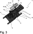
- the Fig. 3 shows the wiper blade adapter 1 with a seal cover 11 and the inlet fluid lines 8, the distributor fluid lines 4 and the connecting channels 9 and the openings 10.
- Two wall sections 12 have latching lugs 13 and the seal cover 11 spring clips 14 which snap into the latching lugs 13 when the seal cover 11 is pressed between the wall sections 12 into their mounting position above the openings 10. This locking connection keeps the seal cover 11 in the assembly position.
- sealing plug 15 as sealing elements 16
- the sealing cover 11 seals all openings 10 in the assembly position.
Landscapes
- Engineering & Computer Science (AREA)
- Mechanical Engineering (AREA)
- Water Supply & Treatment (AREA)
- Physics & Mathematics (AREA)
- Fluid Mechanics (AREA)
- Quality & Reliability (AREA)
- Injection Moulding Of Plastics Or The Like (AREA)
- Moulds For Moulding Plastics Or The Like (AREA)
Abstract
Description
- Die Erfindung betrifft einen Wischblattadapter mit integrierten Fluidleitungen nach der Gattung des unabhängigen Anspruchs.
- Ein Wischblatt wird mit einem Wischarm über einen Wischblattadapter verbunden, um die Montage des Wischblattes am Fahrzeug und das Wechseln zu ermöglichen. Der Wischblattadapter dient dazu, die seitlichen Führungskräfte von dem Wischarm bei der Wischbewegung auf das Wischblatt zu übertragen. Zusätzlich ermöglicht ein Wischblattadapter häufig eine Drehbewegung, damit sich das Wischblatt der Neigung und Krümmung der Scheibe während der Wischbewegung anpassen kann. Dabei sind zweiteilige Ausführungen bekannt, bei denen der Wischblattadapter ein Drehgelenk umfasst, aber auch Ausführungen, bei denen die Verbindung mit dem Wischarm an einer Achse erfolgt, die eine Drehung ermöglicht und auf die Aufnahmeelemente des Wischarms lösbar aufgesetzt werden können.
- Im Stand der Technik sind weiter Wischblätter bekannt, die Düsen zur Ausbringung eines Reinigungsfluids auf eine Scheibe aufweisen und bei denen durch den Wischblattadapter Fluidzuleitungen zum Wischarm geführt werden und an dem Wischblattadapter lösbar verbunden werden können. Die Versorgung der Düsen in dem Wischblatt, beispielsweise in den Endbereichen des Wischblattes, erfordert dabei eine Verteilerfluidleitung längs des Wischblattes. Der Adapter besitzt in diesem Fall waagrechte Auslassfluidleitungen, die mit solchen Verteilerfluidleitungen, beispielsweise ausgeformt in einem Spoiler, verbunden werden. Zugleich wird im oberen Bereich des Wischblattadapters aus dem Wischarm eine Fluidleitung zugeführt. Für diese befindet sich eine im Wesentlichen waagrecht liegende Zuflussfluidleitung mit Anschlüssen in dem Wischblattadapter. Wenn nun der Wischblattadapter als ein Bauteil durch Kunststoffspritzguss hergestellt wird und die Fluidleitungen innerhalb des Wischblattadapters in dieses Kunststoffspritzgussteil integriert werden, müssen Verbindungskanäle zwischen diesen unteren Auslassfluidleitungen und der oder den oberen Zuflussfluidleitungen vorgesehen werden. Bei bekannten und in großer Serie angewandten Verfahren zur Herstellung solcher Hohlkanäle in Spritzgussteilen werden jedoch Kerne an dem Werkzeug vorgesehen, die beim Entformen herausgezogen werden müssen. Dies führt dazu, dass die Verbindungskanäle an einer Seite, entweder unten oder oben, an der sie mit den Auslassfluidleitungen oder Zuflussfluidleitungen verbunden sind nach der Herstellung offen sind und abgedichtet werden müssen.
- Aus der
US 2015/0217731 A1 ist eine Verbindungsvorrichtung zur Verbindung eines Wischblattes mit einem Wischarm bekannt, die zumindest Mittel zur festen Verbindung mit dem Wischblatt und Anschlussmittel für den Wischarm aufweist. Weiterhin umfasst die Verbindungsvorrichtung eine Leitung für eine Waschflüssigkeit mit einer Mehrzahl von Sprühöffnungen zum Aufbringen von Waschflüssigkeit auf die Scheibe. In einem Ausführungsbeispiel ist zwischen einer Zuleitung und einer Verteilerleitung ein Verbindungskanal beschrieben, der an seinem unteren Ende eine Muffe aufweist. Diese entsteht dadurch, dass bei der Produktion die Öffnung des Verbindungskanals versiegelt werden muss, beispielsweise durch Ultraschallschweißen oder Einsetzen eines Dichtungsballs. - Aus der
US 2011/0107541 A1 ist ein Verbindungselement für ein Wischblatt bekannt, dass auch ein hydraulisches Verbindungselement ist. Das Verbindungselement weist eine interne Leitung auf, um von einem oben waagrecht angeordneten Einlass die Flüssigkeit zu einer unteren Verteilerleitung zu leiten. Dabei ist das Verbindungselement in einem Ausführungsbeispiel in der Ebene dieser internen Leitungen, die senkrecht angeordnet sind, geteilt, um dieses herstellen zu können. Die Teile können durch Ultraschallschweißen oder gemeinsames Überspritzen verbunden werden. - Der Wischblattadapter mit den Merkmalen des Hauptanspruchs 1 hat den Vorteil, dass die Dichtungsabdeckung alle Öffnungen der Verbindungskanäle als ein Bauteil gemeinsam überdeckt und, wenn sie eingesetzt wird, in einem Montageschritt alle abdichtet. Beim Entformen des Wischblattadapters aus der Spritzgussform entstehen Öffnungen der Verbindungskanäle die nicht erwünscht sind, sich jedoch nicht vermeiden lassen da im Wesentlichen beispielsweise an einer Oberseite und bis auf eine geringe Winkelabweichung parallel zu einer Scheibenfläche ausgerichtete Zuflussfluidleitungen mit ebenso ausgerichteten, jedoch weiter untenliegenden Verteilerfluidleitungen verbunden werden müssen. Die hierfür erforderlichen Verbindungskanäle müssen im Spritzgusswerkzeug unter Zuhilfenahme eines Kerns gebildet werden, der beim Herausziehen nach einer Seite beim Entformen eine unerwünschte Öffnung hinterlässt. Durch den Einsatz einer Dichtungsabdeckung kann auf kostengünstige Weise mit kurzer Montagezeit und in einem Montageschritt eine Abdichtung aller Öffnungen erfolgen, die zuverlässig ist. Insbesondere ergeben sich Kostenvorteile gegenüber einem weiteren Bearbeitungsschritt, indem beispielsweise durch Kunststoffschweißen mit größerem Zeitaufwand die Öffnungen einzelnen verschlossen werden müssten.
- Durch die in den Unteransprüchen aufgeführten Maßnahmen ergeben sich weiterhin vorteilhafte Weiterbildungen und Verbesserungen der in dem Hauptanspruch angegebenen Merkmale.
- Vorteilhaft bestehen die Dichtungselemente aus Verschlussstopfen, insbesondere aus angespritzten thermoplastischen Elastomermaterialien. Dadurch kann eine besonders zuverlässige Abdichtung erreicht werden.
- In einer Ausgestaltung ist die Dichtungsabdeckung an einer Oberseite angeordnet. Es ist auch denkbar, eine Dichtungsabdeckung an der Unterseite einzusetzen. Besonders vorteilhaft ergeben sich jedoch an der Oberseite bessere Platzverhältnisse zum Einsatz der Dichtungsabdeckung.
- Vorteilhaft kann die Dichtungsabdeckung zwei jeweils zu gegenüberliegenden Seiten hin einseitig freie Federbügel aufweist, die in Rastnasen des Wischblattadapters einrasten können und die Dichtungsabdeckung auf die Öffnungen drücken. Dies ergibt eine sehr einfache Befestigung bei der Montage und eine definierte Anpresskraft, die die Abdichtung der Öffnungen sicherstellt.
- Die Dichtungsabdeckung kann ein Kunststoffspritzteil und die Federbügel können angeformt sein.
- In einer vorteilhaften Ausgestaltung ist die Dichtungsabdeckung zwischen zwei Wandabschnitten geführt positioniert und sind in den Wandabschnitten die Rastnasen angeordnet.
- In einer Ausgestaltung können insgesamt vier Verbindungskanäle zwei Zuflussfluidleitungen und vier Verteilerfluidleitungen verbinden.
- Ausführungsbeispiele sind in den Zeichnungen dargestellt und in der nachfolgenden Beschreibung näher erläutert. Es zeigen:
- Fig. 1
- einen Wischblattadapter an einem Wischblatt,
- Fig. 2
- den Wischblattadapter und
- Fig. 3
- den Wischblattadapter mit einer Dichtungsabdeckung.
- Die
Fig. 1 zeigt einen Wischblattadapter 1 an einem Wischblatt 2 der einen Spoiler 3 hat, in dem sich wiederum eine Fluidleitung befindet. Ein Verteilerfluidleitung 4 ist mit dieser verbunden und an der Kante des Wischblattes 2 sind Düsen ausgebildet, mit denen Reinigungsfluid 5 auf eine Scheibe gespritzt werden kann, wie in der Zeichnung angedeutet. In der Darstellung ist auf den Wischblattadapter 1 ein Kopf 6 eines Wischarms aufgesetzt, wobei zugleich zwei Fluidleitungen 7 des Wischarms an Zuflussfluidleitungen 8 des Wischblattadapters 3 angeschlossen sind. - Die
Fig. 2 zeigt den Wischblattadapter 1 mit den Zuflussfluidleitungen 8 und den Verteilerfluidleitungen 4, die durch Verbindungskanäle 9 verbunden sind. An der Oberseite der Verbindungskanäle 9 ergeben sich Öffnungen 10. - Die
Fig. 3 zeigt den Wischblattadapter 1 mit einer Dichtungsabdeckung 11 und den Zuflussfluidleitungen 8, den Verteilerfluidleitungen 4 und den Verbindungskanälen 9 sowie den Öffnungen 10. Zwei Wandabschnitte 12 weisen Rastnasen 13 auf und die Dichtungsabdeckung 11 Federbügel 14, die in die Rastnasen 13 einrasten, wenn die Dichtungsabdeckung 11 zwischen den Wandabschnitten 12 in ihre Montageposition über den Öffnungen 10 gedrückt wird. Durch diese Rastverbindung wird die Dichtungsabdeckung 11 in der Montageposition gehalten. Durch Verschlussstopfen 15 als Dichtungselemente 16 dichtet die Dichtungsabdeckung 11 alle Öffnungen 10 in der Montageposition ab.
Claims (7)
- Wischblattadapter mit integrierten Fluidleitungen (4,8,9), der zur Verbindung eines Wischblattes (2) mit einem Wischarm dient, wobei der Wischblattadapter (1) als Spritzgussteil aus einem Kunststoff hergestellt ist und eine oder mehrere Verteilerfluidleitungen (4) und weiterhin eine oder mehrere Zuflussfluidleitungen (8) für einen Anschluss an eine Fluidleitung (7) eines Wischarms aufweist, sowie mindestens zwei Verbindungskanälen (9) zwischen Zuflussfluidleitungen (8) und Verteilerfluidleitungen (4),
dadurch gekennzeichnet,
dass auf einer Seite die Verbindungskanäle (9) eine Öffnung (10) ins Freie aufweisen, eine Dichtungsabdeckung (11) alle Öffnungen (10) als getrenntes Bauteil gemeinsam überdeckt und mit Dichtungselementen (16) abdichtet. - Wischblattadapter nach Anspruch 1,
dadurch gekennzeichnet,
dass die Dichtungselemente (16) aus Verschlussstopfen (15) bestehen, insbesondere aus angespritzten thermoplastischen Elastomermaterialien. - Wischblattadapter nach Anspruch 1 oder 2,
dadurch gekennzeichnet,
dass die Dichtungsabdeckung (11) an einer Oberseite angeordnet ist. - Wischblattadapter nach einem der vorhergehenden Ansprüche,
dadurch gekennzeichnet,
dass die Dichtungsabdeckung (11) zwei jeweils zu gegenüberliegenden Seiten hin einseitig freie Federbügel (14) aufweist, die in Rastnasen (13) des Wischblattadapters (1) einrasten können und die Dichtungsabdeckung (11) auf die Öffnungen (10) drücken. - Wischblattadapter nach Anspruch 4,
dadurch gekennzeichnet,
dass die Dichtungsabdeckung (11) ein Kunststoffspritzteil ist und die Federbügel (14) angeformt sind. - Wischblattadapter nach Anspruch 4 oder 5,
dadurch gekennzeichnet,
dass die Dichtungsabdeckung (11) zwischen zwei Wandabschnitten (12) geführt positioniert ist und in den Wandabschnitten (12) die Rastnasen (12) angeordnet sind. - Wischblattadapter nach einem der vorhergehenden Ansprüche,
dadurch gekennzeichnet,
dass insgesamt vier Verbindungskanäle (9) zwei Zuflussfluidleitungen (8) und vier Verteilerfluidleitungen (4) verbinden.
Applications Claiming Priority (1)
| Application Number | Priority Date | Filing Date | Title |
|---|---|---|---|
| DE102018251762.2A DE102018251762A1 (de) | 2018-12-28 | 2018-12-28 | Wischblattadapter mit integrierten Fluidleitungen |
Publications (2)
| Publication Number | Publication Date |
|---|---|
| EP3674149A1 true EP3674149A1 (de) | 2020-07-01 |
| EP3674149B1 EP3674149B1 (de) | 2021-08-18 |
Family
ID=69005274
Family Applications (1)
| Application Number | Title | Priority Date | Filing Date |
|---|---|---|---|
| EP19218760.7A Active EP3674149B1 (de) | 2018-12-28 | 2019-12-20 | Wischblattadapter mit integrierten fluidleitungen |
Country Status (3)
| Country | Link |
|---|---|
| EP (1) | EP3674149B1 (de) |
| CN (1) | CN111376870A (de) |
| DE (1) | DE102018251762A1 (de) |
Citations (5)
| Publication number | Priority date | Publication date | Assignee | Title |
|---|---|---|---|---|
| US20110107541A1 (en) | 2008-07-15 | 2011-05-12 | Valeo Systemes D'essuyage | Hydraulic connector, particularly for motor vehicle windscreen wiper system |
| DE102010025688A1 (de) * | 2010-06-30 | 2012-01-05 | Valeo Wischersysteme Gmbh | Wischblatt zum Reinigen von Fahrzeugscheiben |
| FR2962091A1 (fr) * | 2010-06-30 | 2012-01-06 | Valeo Systemes Dessuyage | Connecteur d'essuie-glace multifonctions |
| EP2692598A1 (de) * | 2012-08-02 | 2014-02-05 | Valeo Systèmes d'Essuyage | Verbindungsvorrichtung zwischen einem Wischerarm und einem Scheibenwischerelement |
| US20150217731A1 (en) | 2012-08-02 | 2015-08-06 | Valeo Systèmes d'Essuyage | Device for connecting a wiper arm and a wiper blade together including an area arranged to receive a plurality of spray openings |
Family Cites Families (5)
| Publication number | Priority date | Publication date | Assignee | Title |
|---|---|---|---|---|
| DE102010052314A1 (de) * | 2010-11-16 | 2012-05-16 | Daimler Ag | Wischblattanordnung und Verbindungsanordnung mit einer Wischblattanordnung und einem Wischarm |
| DE102011050104B4 (de) * | 2011-05-04 | 2024-05-29 | Valeo Systèmes d'Essuyage | Wischblatt für Scheiben von Kraftfahrzeugen |
| DE102013104900A1 (de) * | 2013-05-13 | 2014-11-13 | Valeo Systèmes d'Essuyage | Wischarm für eine Scheibenwischanlage eines Kraftfahrzeugs, Wischblatt sowie Wischvorrichtung |
| DE102015114928A1 (de) * | 2015-09-07 | 2017-03-09 | Valeo Systèmes d'Essuyage | Reinigungseinrichtung zum Reinigen von Fahrzeugscheiben und Wischvorrichtung |
| DE102015226527A1 (de) * | 2015-12-22 | 2017-06-22 | Robert Bosch Gmbh | Wischervorrichtung |
-
2018
- 2018-12-28 DE DE102018251762.2A patent/DE102018251762A1/de active Pending
-
2019
- 2019-12-20 EP EP19218760.7A patent/EP3674149B1/de active Active
- 2019-12-27 CN CN201911379836.6A patent/CN111376870A/zh active Pending
Patent Citations (5)
| Publication number | Priority date | Publication date | Assignee | Title |
|---|---|---|---|---|
| US20110107541A1 (en) | 2008-07-15 | 2011-05-12 | Valeo Systemes D'essuyage | Hydraulic connector, particularly for motor vehicle windscreen wiper system |
| DE102010025688A1 (de) * | 2010-06-30 | 2012-01-05 | Valeo Wischersysteme Gmbh | Wischblatt zum Reinigen von Fahrzeugscheiben |
| FR2962091A1 (fr) * | 2010-06-30 | 2012-01-06 | Valeo Systemes Dessuyage | Connecteur d'essuie-glace multifonctions |
| EP2692598A1 (de) * | 2012-08-02 | 2014-02-05 | Valeo Systèmes d'Essuyage | Verbindungsvorrichtung zwischen einem Wischerarm und einem Scheibenwischerelement |
| US20150217731A1 (en) | 2012-08-02 | 2015-08-06 | Valeo Systèmes d'Essuyage | Device for connecting a wiper arm and a wiper blade together including an area arranged to receive a plurality of spray openings |
Also Published As
| Publication number | Publication date |
|---|---|
| CN111376870A (zh) | 2020-07-07 |
| DE102018251762A1 (de) | 2020-07-02 |
| EP3674149B1 (de) | 2021-08-18 |
Similar Documents
| Publication | Publication Date | Title |
|---|---|---|
| DE102004056835B4 (de) | Wischblatt | |
| EP1998987A1 (de) | Wischblatt | |
| WO2011032818A1 (de) | Filtereinrichtung | |
| EP2990621B1 (de) | Verschlusseinrichtung | |
| DE2410733A1 (de) | Scheibenwaschanlage | |
| DE202015006287U1 (de) | Wasserablaufmechanismus mit rotierendem Wasserablauf und mit Wasserauslassöffnungen zur Realisierung von verschiedenen Wasserablaufsfunktionen versehener Wasserablaufmechanismus | |
| EP3717312A1 (de) | Wischarmsprühvorrichtung | |
| DE112006003924T5 (de) | Lotionspumpe | |
| EP1373709B1 (de) | Kraftstoff-einspritzvorrichtung für brennkraftmaschinen, insbesondere common-rail-injektor, mit einem rücklaufanschluss | |
| DE102016116563A1 (de) | Abgedichtetes gehäuselement sowie abgedichtetes gehäuse und herstellungsverfahren | |
| WO2020074317A1 (de) | Anbauteil für einen wischerarm | |
| EP3897999B1 (de) | Zerstäubersystem mit einem silikon-düsenfeld | |
| DE102013103279A1 (de) | Wischarm für eine Scheibenwischanlage eines Kraftfahrzeugs, Wischblatt und Wischeinrichtung | |
| EP3674149B1 (de) | Wischblattadapter mit integrierten fluidleitungen | |
| DE102015005136A1 (de) | Filtervorrichtung | |
| EP2314364A1 (de) | Filtereinrichtung | |
| EP2314438A1 (de) | Düsenanordnung, Formplatte sowie Verfahren zur Montage einer Düsenvorrichtung | |
| DE202013001405U1 (de) | Regelventileinsatz | |
| DE102015209025B4 (de) | Kugelhahn und Verfahren zu dessen Herstellung | |
| DE102013112712B4 (de) | Wischblatt zum Reinigen einer Fahrzeugscheibe, Verfahren zur Montage eines Wischblatts, Wischvorrichtung und Versorgungselement für eine Waschflüssigkeit | |
| DE4230958C2 (de) | Verfahren zur Herstellung einer Düse | |
| EP2409772A1 (de) | Brausekopfelement für eine Handbrause | |
| DE7613454U1 (de) | Rueckschlagventil | |
| EP3405325A1 (de) | Werkzeug zum anspritzen eines formteils an ein extrudat | |
| EP4271595A1 (de) | System, umfassend ein wischblatt und einen wischarm |
Legal Events
| Date | Code | Title | Description |
|---|---|---|---|
| PUAI | Public reference made under article 153(3) epc to a published international application that has entered the european phase |
Free format text: ORIGINAL CODE: 0009012 |
|
| STAA | Information on the status of an ep patent application or granted ep patent |
Free format text: STATUS: THE APPLICATION HAS BEEN PUBLISHED |
|
| AK | Designated contracting states |
Kind code of ref document: A1 Designated state(s): AL AT BE BG CH CY CZ DE DK EE ES FI FR GB GR HR HU IE IS IT LI LT LU LV MC MK MT NL NO PL PT RO RS SE SI SK SM TR |
|
| AX | Request for extension of the european patent |
Extension state: BA ME |
|
| STAA | Information on the status of an ep patent application or granted ep patent |
Free format text: STATUS: REQUEST FOR EXAMINATION WAS MADE |
|
| 17P | Request for examination filed |
Effective date: 20210111 |
|
| RBV | Designated contracting states (corrected) |
Designated state(s): AL AT BE BG CH CY CZ DE DK EE ES FI FR GB GR HR HU IE IS IT LI LT LU LV MC MK MT NL NO PL PT RO RS SE SI SK SM TR |
|
| GRAP | Despatch of communication of intention to grant a patent |
Free format text: ORIGINAL CODE: EPIDOSNIGR1 |
|
| STAA | Information on the status of an ep patent application or granted ep patent |
Free format text: STATUS: GRANT OF PATENT IS INTENDED |
|
| INTG | Intention to grant announced |
Effective date: 20210525 |
|
| GRAS | Grant fee paid |
Free format text: ORIGINAL CODE: EPIDOSNIGR3 |
|
| GRAA | (expected) grant |
Free format text: ORIGINAL CODE: 0009210 |
|
| STAA | Information on the status of an ep patent application or granted ep patent |
Free format text: STATUS: THE PATENT HAS BEEN GRANTED |
|
| AK | Designated contracting states |
Kind code of ref document: B1 Designated state(s): AL AT BE BG CH CY CZ DE DK EE ES FI FR GB GR HR HU IE IS IT LI LT LU LV MC MK MT NL NO PL PT RO RS SE SI SK SM TR |
|
| REG | Reference to a national code |
Ref country code: GB Ref legal event code: FG4D Free format text: NOT ENGLISH |
|
| REG | Reference to a national code |
Ref country code: CH Ref legal event code: EP |
|
| REG | Reference to a national code |
Ref country code: DE Ref legal event code: R096 Ref document number: 502019002081 Country of ref document: DE |
|
| REG | Reference to a national code |
Ref country code: IE Ref legal event code: FG4D Free format text: LANGUAGE OF EP DOCUMENT: GERMAN Ref country code: AT Ref legal event code: REF Ref document number: 1421377 Country of ref document: AT Kind code of ref document: T Effective date: 20210915 |
|
| REG | Reference to a national code |
Ref country code: LT Ref legal event code: MG9D |
|
| REG | Reference to a national code |
Ref country code: NL Ref legal event code: MP Effective date: 20210818 |
|
| PG25 | Lapsed in a contracting state [announced via postgrant information from national office to epo] |
Ref country code: RS Free format text: LAPSE BECAUSE OF FAILURE TO SUBMIT A TRANSLATION OF THE DESCRIPTION OR TO PAY THE FEE WITHIN THE PRESCRIBED TIME-LIMIT Effective date: 20210818 Ref country code: SE Free format text: LAPSE BECAUSE OF FAILURE TO SUBMIT A TRANSLATION OF THE DESCRIPTION OR TO PAY THE FEE WITHIN THE PRESCRIBED TIME-LIMIT Effective date: 20210818 Ref country code: ES Free format text: LAPSE BECAUSE OF FAILURE TO SUBMIT A TRANSLATION OF THE DESCRIPTION OR TO PAY THE FEE WITHIN THE PRESCRIBED TIME-LIMIT Effective date: 20210818 Ref country code: BG Free format text: LAPSE BECAUSE OF FAILURE TO SUBMIT A TRANSLATION OF THE DESCRIPTION OR TO PAY THE FEE WITHIN THE PRESCRIBED TIME-LIMIT Effective date: 20211118 Ref country code: LT Free format text: LAPSE BECAUSE OF FAILURE TO SUBMIT A TRANSLATION OF THE DESCRIPTION OR TO PAY THE FEE WITHIN THE PRESCRIBED TIME-LIMIT Effective date: 20210818 Ref country code: FI Free format text: LAPSE BECAUSE OF FAILURE TO SUBMIT A TRANSLATION OF THE DESCRIPTION OR TO PAY THE FEE WITHIN THE PRESCRIBED TIME-LIMIT Effective date: 20210818 Ref country code: HR Free format text: LAPSE BECAUSE OF FAILURE TO SUBMIT A TRANSLATION OF THE DESCRIPTION OR TO PAY THE FEE WITHIN THE PRESCRIBED TIME-LIMIT Effective date: 20210818 Ref country code: PT Free format text: LAPSE BECAUSE OF FAILURE TO SUBMIT A TRANSLATION OF THE DESCRIPTION OR TO PAY THE FEE WITHIN THE PRESCRIBED TIME-LIMIT Effective date: 20211220 Ref country code: NO Free format text: LAPSE BECAUSE OF FAILURE TO SUBMIT A TRANSLATION OF THE DESCRIPTION OR TO PAY THE FEE WITHIN THE PRESCRIBED TIME-LIMIT Effective date: 20211118 |
|
| PG25 | Lapsed in a contracting state [announced via postgrant information from national office to epo] |
Ref country code: PL Free format text: LAPSE BECAUSE OF FAILURE TO SUBMIT A TRANSLATION OF THE DESCRIPTION OR TO PAY THE FEE WITHIN THE PRESCRIBED TIME-LIMIT Effective date: 20210818 Ref country code: LV Free format text: LAPSE BECAUSE OF FAILURE TO SUBMIT A TRANSLATION OF THE DESCRIPTION OR TO PAY THE FEE WITHIN THE PRESCRIBED TIME-LIMIT Effective date: 20210818 Ref country code: GR Free format text: LAPSE BECAUSE OF FAILURE TO SUBMIT A TRANSLATION OF THE DESCRIPTION OR TO PAY THE FEE WITHIN THE PRESCRIBED TIME-LIMIT Effective date: 20211119 |
|
| PG25 | Lapsed in a contracting state [announced via postgrant information from national office to epo] |
Ref country code: NL Free format text: LAPSE BECAUSE OF FAILURE TO SUBMIT A TRANSLATION OF THE DESCRIPTION OR TO PAY THE FEE WITHIN THE PRESCRIBED TIME-LIMIT Effective date: 20210818 |
|
| PG25 | Lapsed in a contracting state [announced via postgrant information from national office to epo] |
Ref country code: DK Free format text: LAPSE BECAUSE OF FAILURE TO SUBMIT A TRANSLATION OF THE DESCRIPTION OR TO PAY THE FEE WITHIN THE PRESCRIBED TIME-LIMIT Effective date: 20210818 |
|
| REG | Reference to a national code |
Ref country code: DE Ref legal event code: R097 Ref document number: 502019002081 Country of ref document: DE |
|
| PG25 | Lapsed in a contracting state [announced via postgrant information from national office to epo] |
Ref country code: SM Free format text: LAPSE BECAUSE OF FAILURE TO SUBMIT A TRANSLATION OF THE DESCRIPTION OR TO PAY THE FEE WITHIN THE PRESCRIBED TIME-LIMIT Effective date: 20210818 Ref country code: SK Free format text: LAPSE BECAUSE OF FAILURE TO SUBMIT A TRANSLATION OF THE DESCRIPTION OR TO PAY THE FEE WITHIN THE PRESCRIBED TIME-LIMIT Effective date: 20210818 Ref country code: RO Free format text: LAPSE BECAUSE OF FAILURE TO SUBMIT A TRANSLATION OF THE DESCRIPTION OR TO PAY THE FEE WITHIN THE PRESCRIBED TIME-LIMIT Effective date: 20210818 Ref country code: EE Free format text: LAPSE BECAUSE OF FAILURE TO SUBMIT A TRANSLATION OF THE DESCRIPTION OR TO PAY THE FEE WITHIN THE PRESCRIBED TIME-LIMIT Effective date: 20210818 Ref country code: CZ Free format text: LAPSE BECAUSE OF FAILURE TO SUBMIT A TRANSLATION OF THE DESCRIPTION OR TO PAY THE FEE WITHIN THE PRESCRIBED TIME-LIMIT Effective date: 20210818 Ref country code: AL Free format text: LAPSE BECAUSE OF FAILURE TO SUBMIT A TRANSLATION OF THE DESCRIPTION OR TO PAY THE FEE WITHIN THE PRESCRIBED TIME-LIMIT Effective date: 20210818 |
|
| PLBE | No opposition filed within time limit |
Free format text: ORIGINAL CODE: 0009261 |
|
| STAA | Information on the status of an ep patent application or granted ep patent |
Free format text: STATUS: NO OPPOSITION FILED WITHIN TIME LIMIT |
|
| 26N | No opposition filed |
Effective date: 20220519 |
|
| PG25 | Lapsed in a contracting state [announced via postgrant information from national office to epo] |
Ref country code: MC Free format text: LAPSE BECAUSE OF FAILURE TO SUBMIT A TRANSLATION OF THE DESCRIPTION OR TO PAY THE FEE WITHIN THE PRESCRIBED TIME-LIMIT Effective date: 20210818 Ref country code: IT Free format text: LAPSE BECAUSE OF FAILURE TO SUBMIT A TRANSLATION OF THE DESCRIPTION OR TO PAY THE FEE WITHIN THE PRESCRIBED TIME-LIMIT Effective date: 20210818 |
|
| PG25 | Lapsed in a contracting state [announced via postgrant information from national office to epo] |
Ref country code: SI Free format text: LAPSE BECAUSE OF FAILURE TO SUBMIT A TRANSLATION OF THE DESCRIPTION OR TO PAY THE FEE WITHIN THE PRESCRIBED TIME-LIMIT Effective date: 20210818 |
|
| REG | Reference to a national code |
Ref country code: BE Ref legal event code: MM Effective date: 20211231 |
|
| PG25 | Lapsed in a contracting state [announced via postgrant information from national office to epo] |
Ref country code: LU Free format text: LAPSE BECAUSE OF NON-PAYMENT OF DUE FEES Effective date: 20211220 Ref country code: IE Free format text: LAPSE BECAUSE OF NON-PAYMENT OF DUE FEES Effective date: 20211220 |
|
| PG25 | Lapsed in a contracting state [announced via postgrant information from national office to epo] |
Ref country code: BE Free format text: LAPSE BECAUSE OF NON-PAYMENT OF DUE FEES Effective date: 20211231 |
|
| PG25 | Lapsed in a contracting state [announced via postgrant information from national office to epo] |
Ref country code: CY Free format text: LAPSE BECAUSE OF FAILURE TO SUBMIT A TRANSLATION OF THE DESCRIPTION OR TO PAY THE FEE WITHIN THE PRESCRIBED TIME-LIMIT Effective date: 20210818 |
|
| PG25 | Lapsed in a contracting state [announced via postgrant information from national office to epo] |
Ref country code: HU Free format text: LAPSE BECAUSE OF FAILURE TO SUBMIT A TRANSLATION OF THE DESCRIPTION OR TO PAY THE FEE WITHIN THE PRESCRIBED TIME-LIMIT; INVALID AB INITIO Effective date: 20191220 |
|
| REG | Reference to a national code |
Ref country code: CH Ref legal event code: PL |
|
| PG25 | Lapsed in a contracting state [announced via postgrant information from national office to epo] |
Ref country code: LI Free format text: LAPSE BECAUSE OF NON-PAYMENT OF DUE FEES Effective date: 20221231 Ref country code: CH Free format text: LAPSE BECAUSE OF NON-PAYMENT OF DUE FEES Effective date: 20221231 |
|
| PGFP | Annual fee paid to national office [announced via postgrant information from national office to epo] |
Ref country code: FR Payment date: 20231219 Year of fee payment: 5 |
|
| PG25 | Lapsed in a contracting state [announced via postgrant information from national office to epo] |
Ref country code: MK Free format text: LAPSE BECAUSE OF FAILURE TO SUBMIT A TRANSLATION OF THE DESCRIPTION OR TO PAY THE FEE WITHIN THE PRESCRIBED TIME-LIMIT Effective date: 20210818 |
|
| PGFP | Annual fee paid to national office [announced via postgrant information from national office to epo] |
Ref country code: DE Payment date: 20240227 Year of fee payment: 5 |