EP3674085A1 - Image forming device and image forming control method - Google Patents
Image forming device and image forming control method Download PDFInfo
- Publication number
- EP3674085A1 EP3674085A1 EP19212774.4A EP19212774A EP3674085A1 EP 3674085 A1 EP3674085 A1 EP 3674085A1 EP 19212774 A EP19212774 A EP 19212774A EP 3674085 A1 EP3674085 A1 EP 3674085A1
- Authority
- EP
- European Patent Office
- Prior art keywords
- recording
- image forming
- width direction
- drive data
- recording medium
- Prior art date
- Legal status (The legal status is an assumption and is not a legal conclusion. Google has not performed a legal analysis and makes no representation as to the accuracy of the status listed.)
- Withdrawn
Links
Images




Classifications
-
- B—PERFORMING OPERATIONS; TRANSPORTING
- B41—PRINTING; LINING MACHINES; TYPEWRITERS; STAMPS
- B41J—TYPEWRITERS; SELECTIVE PRINTING MECHANISMS, i.e. MECHANISMS PRINTING OTHERWISE THAN FROM A FORME; CORRECTION OF TYPOGRAPHICAL ERRORS
- B41J2/00—Typewriters or selective printing mechanisms characterised by the printing or marking process for which they are designed
- B41J2/005—Typewriters or selective printing mechanisms characterised by the printing or marking process for which they are designed characterised by bringing liquid or particles selectively into contact with a printing material
- B41J2/01—Ink jet
- B41J2/135—Nozzles
- B41J2/145—Arrangement thereof
- B41J2/155—Arrangement thereof for line printing
-
- B—PERFORMING OPERATIONS; TRANSPORTING
- B41—PRINTING; LINING MACHINES; TYPEWRITERS; STAMPS
- B41J—TYPEWRITERS; SELECTIVE PRINTING MECHANISMS, i.e. MECHANISMS PRINTING OTHERWISE THAN FROM A FORME; CORRECTION OF TYPOGRAPHICAL ERRORS
- B41J29/00—Details of, or accessories for, typewriters or selective printing mechanisms not otherwise provided for
- B41J29/38—Drives, motors, controls or automatic cut-off devices for the entire printing mechanism
- B41J29/393—Devices for controlling or analysing the entire machine ; Controlling or analysing mechanical parameters involving printing of test patterns
-
- B—PERFORMING OPERATIONS; TRANSPORTING
- B41—PRINTING; LINING MACHINES; TYPEWRITERS; STAMPS
- B41J—TYPEWRITERS; SELECTIVE PRINTING MECHANISMS, i.e. MECHANISMS PRINTING OTHERWISE THAN FROM A FORME; CORRECTION OF TYPOGRAPHICAL ERRORS
- B41J11/00—Devices or arrangements of selective printing mechanisms, e.g. ink-jet printers or thermal printers, for supporting or handling copy material in sheet or web form
- B41J11/007—Conveyor belts or like feeding devices
-
- B—PERFORMING OPERATIONS; TRANSPORTING
- B41—PRINTING; LINING MACHINES; TYPEWRITERS; STAMPS
- B41J—TYPEWRITERS; SELECTIVE PRINTING MECHANISMS, i.e. MECHANISMS PRINTING OTHERWISE THAN FROM A FORME; CORRECTION OF TYPOGRAPHICAL ERRORS
- B41J11/00—Devices or arrangements of selective printing mechanisms, e.g. ink-jet printers or thermal printers, for supporting or handling copy material in sheet or web form
- B41J11/008—Controlling printhead for accurately positioning print image on printing material, e.g. with the intention to control the width of margins
-
- B—PERFORMING OPERATIONS; TRANSPORTING
- B41—PRINTING; LINING MACHINES; TYPEWRITERS; STAMPS
- B41J—TYPEWRITERS; SELECTIVE PRINTING MECHANISMS, i.e. MECHANISMS PRINTING OTHERWISE THAN FROM A FORME; CORRECTION OF TYPOGRAPHICAL ERRORS
- B41J2/00—Typewriters or selective printing mechanisms characterised by the printing or marking process for which they are designed
- B41J2/005—Typewriters or selective printing mechanisms characterised by the printing or marking process for which they are designed characterised by bringing liquid or particles selectively into contact with a printing material
- B41J2/01—Ink jet
- B41J2/015—Ink jet characterised by the jet generation process
- B41J2/04—Ink jet characterised by the jet generation process generating single droplets or particles on demand
- B41J2/045—Ink jet characterised by the jet generation process generating single droplets or particles on demand by pressure, e.g. electromechanical transducers
- B41J2/04501—Control methods or devices therefor, e.g. driver circuits, control circuits
- B41J2/04505—Control methods or devices therefor, e.g. driver circuits, control circuits aiming at correcting alignment
-
- B—PERFORMING OPERATIONS; TRANSPORTING
- B41—PRINTING; LINING MACHINES; TYPEWRITERS; STAMPS
- B41J—TYPEWRITERS; SELECTIVE PRINTING MECHANISMS, i.e. MECHANISMS PRINTING OTHERWISE THAN FROM A FORME; CORRECTION OF TYPOGRAPHICAL ERRORS
- B41J2/00—Typewriters or selective printing mechanisms characterised by the printing or marking process for which they are designed
- B41J2/005—Typewriters or selective printing mechanisms characterised by the printing or marking process for which they are designed characterised by bringing liquid or particles selectively into contact with a printing material
- B41J2/01—Ink jet
- B41J2/015—Ink jet characterised by the jet generation process
- B41J2/04—Ink jet characterised by the jet generation process generating single droplets or particles on demand
- B41J2/045—Ink jet characterised by the jet generation process generating single droplets or particles on demand by pressure, e.g. electromechanical transducers
- B41J2/04501—Control methods or devices therefor, e.g. driver circuits, control circuits
- B41J2/04508—Control methods or devices therefor, e.g. driver circuits, control circuits aiming at correcting other parameters
-
- B—PERFORMING OPERATIONS; TRANSPORTING
- B41—PRINTING; LINING MACHINES; TYPEWRITERS; STAMPS
- B41J—TYPEWRITERS; SELECTIVE PRINTING MECHANISMS, i.e. MECHANISMS PRINTING OTHERWISE THAN FROM A FORME; CORRECTION OF TYPOGRAPHICAL ERRORS
- B41J2/00—Typewriters or selective printing mechanisms characterised by the printing or marking process for which they are designed
- B41J2/005—Typewriters or selective printing mechanisms characterised by the printing or marking process for which they are designed characterised by bringing liquid or particles selectively into contact with a printing material
- B41J2/01—Ink jet
- B41J2/015—Ink jet characterised by the jet generation process
- B41J2/04—Ink jet characterised by the jet generation process generating single droplets or particles on demand
- B41J2/045—Ink jet characterised by the jet generation process generating single droplets or particles on demand by pressure, e.g. electromechanical transducers
- B41J2/04501—Control methods or devices therefor, e.g. driver circuits, control circuits
- B41J2/04581—Control methods or devices therefor, e.g. driver circuits, control circuits controlling heads based on piezoelectric elements
-
- B—PERFORMING OPERATIONS; TRANSPORTING
- B41—PRINTING; LINING MACHINES; TYPEWRITERS; STAMPS
- B41J—TYPEWRITERS; SELECTIVE PRINTING MECHANISMS, i.e. MECHANISMS PRINTING OTHERWISE THAN FROM A FORME; CORRECTION OF TYPOGRAPHICAL ERRORS
- B41J2/00—Typewriters or selective printing mechanisms characterised by the printing or marking process for which they are designed
- B41J2/005—Typewriters or selective printing mechanisms characterised by the printing or marking process for which they are designed characterised by bringing liquid or particles selectively into contact with a printing material
- B41J2/01—Ink jet
- B41J2/07—Ink jet characterised by jet control
- B41J2/11—Ink jet characterised by jet control for ink spray
-
- B—PERFORMING OPERATIONS; TRANSPORTING
- B41—PRINTING; LINING MACHINES; TYPEWRITERS; STAMPS
- B41J—TYPEWRITERS; SELECTIVE PRINTING MECHANISMS, i.e. MECHANISMS PRINTING OTHERWISE THAN FROM A FORME; CORRECTION OF TYPOGRAPHICAL ERRORS
- B41J2/00—Typewriters or selective printing mechanisms characterised by the printing or marking process for which they are designed
- B41J2/005—Typewriters or selective printing mechanisms characterised by the printing or marking process for which they are designed characterised by bringing liquid or particles selectively into contact with a printing material
- B41J2/01—Ink jet
- B41J2/21—Ink jet for multi-colour printing
- B41J2/2132—Print quality control characterised by dot disposition, e.g. for reducing white stripes or banding
-
- B—PERFORMING OPERATIONS; TRANSPORTING
- B41—PRINTING; LINING MACHINES; TYPEWRITERS; STAMPS
- B41J—TYPEWRITERS; SELECTIVE PRINTING MECHANISMS, i.e. MECHANISMS PRINTING OTHERWISE THAN FROM A FORME; CORRECTION OF TYPOGRAPHICAL ERRORS
- B41J2/00—Typewriters or selective printing mechanisms characterised by the printing or marking process for which they are designed
- B41J2/005—Typewriters or selective printing mechanisms characterised by the printing or marking process for which they are designed characterised by bringing liquid or particles selectively into contact with a printing material
- B41J2/01—Ink jet
- B41J2/21—Ink jet for multi-colour printing
- B41J2/2132—Print quality control characterised by dot disposition, e.g. for reducing white stripes or banding
- B41J2/2146—Print quality control characterised by dot disposition, e.g. for reducing white stripes or banding for line print heads
-
- B—PERFORMING OPERATIONS; TRANSPORTING
- B41—PRINTING; LINING MACHINES; TYPEWRITERS; STAMPS
- B41J—TYPEWRITERS; SELECTIVE PRINTING MECHANISMS, i.e. MECHANISMS PRINTING OTHERWISE THAN FROM A FORME; CORRECTION OF TYPOGRAPHICAL ERRORS
- B41J2202/00—Embodiments of or processes related to ink-jet or thermal heads
- B41J2202/01—Embodiments of or processes related to ink-jet heads
- B41J2202/20—Modules
Definitions
- the present invention relates to an image forming device and an image forming control method.
- image forming devices each of which causes multiple nozzles to eject ink to make the ink attach onto a recording medium and records an image (including three-dimensional structures, film formation not having colors, and the like) on the recording medium.
- image forming devices include a single pass type image forming device which records an image without performing scanning of nozzles by moving the recording medium relative to the nozzles in a predetermined direction and arranging the nozzles over the recordable width of the recording medium in a width direction crossing the predetermined direction, in order to meet the requirements of high speed and high accuracy.
- JP 2009-51066A discloses a technique of adjusting the use range of nozzles in each of the blocks according to the relative position of the block by assembling adjacent blocks to overlap each other a little in the width direction.
- An object of the present invention is to provide an image forming device and an image forming control method which can suppress the degradation of image quality and perform the recording operation more easily.
- an image forming device reflecting one aspect of the present invention includes: a conveyance section that conveys a recording medium; an obtaining section that obtains movement information of the recording medium which is conveyed; a recording operation section that has a plurality of recording elements which perform a recording operation; and a controller.
- the plurality of recording elements are divided into a plurality of element groups, each of the element groups having a plurality of recording elements, the plurality of element groups perform image formation in respective recording ranges that are different in a width direction which is orthogonal to a movement direction of the conveyed recording medium in a plane parallel to the recording medium, recording ranges that are adjacent in the width direction among the recording ranges partially overlap in the width direction, setting is performed to drive data related to the recording operation so that a recording element does not perform the recording operation, the recording element corresponding to a predetermined range from an end in the width direction in each of the recording ranges, for each of the element groups, the controller changes a correspondence relationship between the drive data and the recording elements so that the drive data, to which the setting is performed and which is associated with each drive element, is associated with each of the recording elements at positions according to a positional shift amount in the width direction of the recording medium, the positional shift amount being obtained based on the movement information for each position in the movement direction, and the predetermined range is determined to be equal to
- the conveyance section has a placement member on which the recording medium is placed, and the positional shift amount is obtained based on the movement information related to meandering during movement of the placement member.
- the placement member is an endless belt.
- an index indicating a reference position is provided to the placement member, and the obtaining section obtains the movement information of the recording medium based on a detection result of the index.
- the controller when drive data corresponding to a part of the recording elements does not exist by change of the correspondence relationship, the controller adds data not causing the part of the recording elements to perform the recording operation as the drive data corresponding to the part of the recording elements.
- the controller deletes the part of the drive data.
- the image forming device includes a plurality of first storages corresponding to the respective element groups, wherein the drive data is stored in the plurality of first storages for ranges respectively corresponding to the recording ranges of the element groups, and the drive data is processed in parallel.
- the first storages are provided on respective separate substrates.
- the image forming device includes a second storage that stores reference data indicating a pattern of the periodical change of the positional shift amount, wherein the controller obtains the positional shift amount based on the movement information by using the reference data.
- the same reference data is retained so as to correspond to each of the element groups of the recording operation section.
- the controller has individual controllers corresponding to the respective element groups, and the movement information is synchronized and input to the individual controllers.
- the obtaining section has an encoder that measures a conveyance movement amount by the conveyance section.
- the image forming device includes a plurality of recording operation sections, each of the recording operation sections being the recording operation section, wherein the plurality of recording operation sections are arranged at positions that are different in the movement direction of the conveyed recording medium, and at least a part of the recording operation sections performs the recording operation with a color different from a color of a recording operation section other than the part of the recording operation sections.
- an image forming control method reflecting one aspect of the present invention is an image forming control method of an image forming device including: a conveyance section that conveys a recording medium; an obtaining section that obtains movement information of the recording medium which is conveyed; and a recording operation section that has a plurality of recording elements which perform a recording operation, wherein the plurality of recording elements are divided into a plurality of element groups, each of the element groups having a plurality of recording elements, the plurality of element groups perform image formation in respective recording ranges that are different in a width direction which is orthogonal to a movement direction of the conveyed recording medium in a plane parallel to the recording medium, and recording ranges that are adjacent in the width direction among the recording ranges partially overlap in the width direction, the image forming control method including: an initial setting step that is performing setting to drive data related to the recording operation so that a recording element does not perform the recording operation, the recording element corresponding to a
- FIG. 1 is the entire perspective view of an inkjet recording device 100 which is the embodiment of an image forming device of the present invention.
- the inkjet recording device 100 has a plurality of, eight in the embodiment, line heads, and can perform recording of a color image by ejecting the ink with the single pass method.
- the inkjet recording device 100 includes: a conveyance section 10; recording operation sections 20; an ink supplying section 30; a conveyance detecting section 41; an image detecting section 42, and the like.
- the conveyance section 10 includes: a drive roller 11; a conveyance driving section 12, a conveyance belt 14 (placement member); and the like.
- the conveyance driving section 12 has a rotation motor which causes the drive roller 11 to perform a rotation operation at a predetermined speed.
- the conveyance belt 14, which is endless, is wound around the drive roller 11 in addition to following rollers not shown in the drawings, and the conveyance belt 14 performs a rotary movement by the rotation of the drive roller 11.
- the conveyance section 10 places the recording medium in a predetermined range on the conveyance surface, and conveys the recording medium in the rotary movement direction (movement direction of the recording medium at the time of conveyance, that is, conveyance direction) in accordance with the rotary movement of the conveyance belt 14.
- the type of the recording medium is not especially limited, the recording medium in the embodiment is a continuous fabric or the like.
- a roll type fabric is sequentially rolled out to be placed on the conveyance surface, and can be conveyed.
- Each of the recording operation sections 20 includes a carriage 22, a carriage elevation section 23, and the like.
- a set number (eight, in the embodiment) of the recording operation sections 20 are provided (a plurality of recording operation sections 20 are provided), the set number corresponding to the color number of inks.
- Each of the carriages 22 is arranged above (in the height direction) the conveyance surface of the recording medium by the conveyance section 10 so as to extend in a direction crossing the conveyance direction of the conveyance by the conveyance section 10, which is the width direction orthogonal to the conveyance direction in the embodiment, in the plane parallel to the conveyance surface.
- a head unit 21 (see FIG.
- each of the eight (a plurality of) head units 21, may be determined as needed according to the recording resolution, the size of the recording medium which can be recorded by the inkjet recording device 100, and the like.
- the plurality of carriages 22, that is, the recording operation sections 20 are provided at positions which are different from each other in the conveyance direction.
- Each of the carriages 22 is provided so as to be able to change the position in the height direction by the carriage elevation section 23, and the distance from the conveyance surface to the head unit 21 is changed in accordance with the movement of the carriage 22.
- the ink is ejected from the nozzles by the recording elements 26 performing the recording operation (ejecting the ink), and thereby an image is recorded (formed) on the recording medium.
- the carriage elevation section 23 changes the distance of the carriage 22 from the conveyance surface.
- the carriage elevation section 23 includes elevation motors 232, electromagnetic brakes 233, beam members 234, supporting sections 235, and the like.
- Two beam members 234 are provided in nearly parallel in the direction crossing the conveyance direction (orthogonal to the conveyance direction in the embodiment, that is, width direction) above the conveyance belt 14 (conveyance surface side of the recording medium).
- the supporting sections 235 are respectively fixed to both of the ends of the beam members 234.
- the elevation motors 232, the electromagnetic brakes 233 and the carriage 22 are attached to the supporting sections 235.
- the carriage 22 is positioned by moving up or down in accordance with the operations of the elevation motors 232 and electromagnetic brakes 233 which are driven on the basis of the control signal from the controller 50 (see FIG. 3 ).
- the elevation motors 232 move the carriage 22 at a predetermined elevation speed.
- the elevation motors 232 for example, servomotors or stepping motors are used.
- the electromagnetic brakes 233 maintain the fixed state of the carriage 22.
- the fixed state is released according to the drive signal, and thereby the movement of the carriage 22 by the elevation motors 232 becomes possible temporarily. That is, in a normal state including the time of disconnection of the power supply, the electromagnetic brakes 233 fix the carriage 22.
- the electromagnetic brakes 233 for example, disc brakes are used.
- the ink supplying section 30 contains inks of respective colors used in the image formation, and supplies the inks to the head units 21.
- ink storing tanks 31 of the respective colors are arranged in a dedicated rack 32, and connected to the head units 21 which eject the inks of the respective colors via a piping such as a tube.
- the inks of the respective colors are not especially limited. However, in the embodiment, the colors of the inks are eight colors which are different from each other, and include C (cyan), M (magenta), Y (yellow) and K (black).
- inks of P (pink), S (sky), G (gray) and O (orange) (at least a part of the inks is an ink(s) of a color(s) different from the ink(s) other than the part of the inks) can be further supplied.
- the inks of the respective colors are ejected as respective minute dots and attached to the recording medium by the nozzles of the head units 21 to which the respective inks were supplied.
- a mixed color image expressed by the densities corresponding to the number of minute dots, the size of dots (droplet amount) and the like and a combination thereof is formed.
- the colors of inks which are stored in the ink storing tank 31 and supplied to the head units 21 may be exchangeable.
- the conveyance detecting section 41 is located on the upstream side in the conveyance direction of the recording operation sections 20, and detects an origin sign O of the conveyance belt 14 (index indicating the reference position; see FIG. 6 ), and outputs the detection signal.
- the origin sign O is provided at a specific position in the rotary movement direction at a predetermined distance from an end in the width direction of the endless conveyance belt 14.
- the conveyance detecting section 41 detects the origin sign O for each rotation of the conveyance belt 14, and outputs the timing. If necessary, the conveyance detecting section 41 may be able to measure and output the position in the width direction of the origin sign O (which may be a relative position from the reference position).
- the origin sign O may be a sign of a color different from the color of the other portion or may be a hole provided in the conveyance belt 14, for example.
- the conveyance detecting section 41 may be a sensor which reads the origin sign O or obtains the detected intensity of the reflected light.
- the conveyance detecting section 41 may be a through-beam type light sensor or the like which penetrates the hole part and detects the incident light on the opposite side.
- the light is not limited to visible light, and may be infrared light and the like.
- the conveyance detecting section 41 may be able to directly detect and identify the position (end) or the like in the width direction of the recording medium.
- the image detecting section 42 is provided on the downstream side in the conveyance direction of the recording operation sections 20, and images and reads the surface of the recording medium on which an image was formed by the recording operation sections 20 (or which passed without image formation).
- the image detecting section 42 may include a lighting part not shown in the drawings. The lighting part irradiates the surface to be imaged by the image detecting section 42 (surface of recording medium) nearly evenly.
- the image detecting section 42 includes a one dimensional imaging sensor, for example.
- a plurality of imaging elements are arranged at least over the width of the conveyance belt 14 in the width direction.
- the recording medium is moved in the conveyance direction by the operation of the conveyance section 10, and thereby the image detecting section 42 can perform two dimensional imaging on the recording medium.
- the imaging sensor the CCD sensor (Charge Coupled Device), the CMOS sensor (Complementary Metal Oxide Semiconductor) and the like are used.
- Each of these imaging sensors performs, with the imaging elements, the imaging operation of outputting the electric charge amount and the voltage corresponding to the light amount input to the light receiving element from the surface of the recording medium via an optical system (lens).
- the imaging sensor can perform imaging at each wavelength band (a plurality of wavelength bands) of RGB, and the color read image can be obtained by the image detecting section 42.
- the image detecting section 42 may be used to specify after-mentioned meandering information 63 and 255 in advance (for example, detection of a change pattern of shift amount in the width direction of a straight line in the conveyance direction formed on the recording medium).
- the conveyance detecting section 41 and the image detecting section 42 may be able to change the distance from the conveyance surface similarly to the carriage 22.
- FIG. 2 is a bottom surface view showing the surface facing the conveyance surface in the head unit 21.
- each of the head units 21 has a same shape and a same configuration, the description here will be made for any arbitrary one of the head units 21.
- each of the recording heads 211 there is provided a nozzle array in which nozzle openings 27a of a plurality of nozzles 27 are arrayed in the width direction at a predetermined nozzle pitch.
- the positions of nozzle openings 27a may be different in the conveyance direction as long as the nozzle openings 27a are arrayed at a predetermined interval in the width direction.
- nozzle openings 27a The number and size of nozzle openings 27a shown in this drawing is shown for explanation, and the number of nozzle openings 27a is actually larger than the number shown in the drawing, and the size of the nozzle openings 27a is sufficiently small compared to the width of the arrangement range in the width direction of the nozzle openings 27a.
- the eight recording heads 211 included in one head unit 21 are arranged in a staggered manner at different positions.
- the arrangement ranges in the width direction of nozzle openings 27a in the respective recording heads 211 are located at positions different from each other, and the image formation can be performed in recording ranges different from each other according to these arrangement ranges.
- the ends of the arrangement ranges in the width direction of the nozzle openings 27a in adjacent recording heads 211 are a little overlapping with each other.
- the head unit 21 is configured to be able to eject the ink from the plurality of nozzles which are divided into each of the recording heads 211 at the above nozzle pitch over the entire width (both ends may have a little margin) of the recording medium M in the width direction by combination of the recording ranges in the width direction of the respective eight recording heads 211.
- FIG. 3 is a block diagram showing the functional configuration of the inkjet recording device 100.
- the inkjet recording device 100 includes the conveyance section 10, the recording operation sections 20, the detecting section 40 (obtaining section), a controller 50, a storage 60, a communicating section 70, a display 81, an operation receiving section 82, a bus 90 and the like.
- the conveyance section 10 has the above-mentioned conveyance driving section 12.
- the detecting section 40 includes the above-mentioned conveyance detecting section 41 and the image detecting section 42.
- Each of the recording operation sections 20 includes a carriage driving section 24, a head driving section 25, and the like.
- the carriage driving section 24 outputs a drive signal to the above-mentioned elevation motor 232, the electromagnetic brake 233 and the like, and operates or fixes them.
- the electromechanical conversion element 252 and the nozzle 27 are included in the recording element 26.
- the head driving section 25 includes a recording controller 251 (individual controller).
- the recording controller 251 outputs a drive signal causing the pressure change of the ink in the ink flow path communicated with each of the nozzles 27 in the recording head 211 on the basis of the control of the controller 50.
- the electromechanical conversion element 252 in the embodiment, piezoelectric element
- the electromechanical conversion element 252 causes deformation according to the applied voltage, that is, the output voltage of the drive signal, and thereby deforms the ink flow path, especially the pressure chamber, the pressure chamber being formed by determining the size and shape for causing the pressure change appropriately.
- the drive signal one or a plurality of voltage waveform patterns are determined in advance, whether to output the drive signal in the voltage waveform pattern to the electromechanical conversion element 252 corresponding to each of the nozzles is determined according to the control signal and drive data (halftone image data) from the controller 50.
- the ink which was pushed out from the nozzle opening 27a by the deformation operation of the electromechanical conversion element 252 (recording operation of the recording element 26) by the drive signal is separated from the ink in the ink flow path by an appropriate amount, and ejected as ink droplets.
- the output period of the drive signal may be fixed at a single period, or minute adjustment may be allowed. Alternatively, the output period of the drive signal may be determined to be changeable according to the conveyance speed of the recording medium by the conveyance section 10 and the resolution in the conveyance direction of the image.
- the recording controller 251 in the embodiment is provided so as to correspond to each of the plurality of (eight) recording heads 211, and independently operates on the basis of the synchronization signal from an encoder 43 and the conveyance detecting section 41.
- the recording controller 251 controls the recording operation of each of the recording heads 211 at the output period of the drive signal on the basis of the drive data of the image range to be recorded by the nozzles of the corresponding recording head 211.
- the controller 50 and the recording controller 251 are included in a controller in the embodiment of the present invention.
- the detecting section 40 has an encoder 43 in addition to the above-mentioned conveyance detecting section 41 and the image detecting section 42.
- the encoder 43 detects the rotation of drive motor or drive roller 11 of the conveyance driving section 12, and outputs a signal corresponding to the rotation direction for each rotation of a predetermined angle.
- the interval from the previous signal output indicates the rotation speed, that is, the conveyance speed of the recording medium.
- the position in the rotation direction of the conveyance belt 14 and the position of the recording medium which is conveyed are specified by the detection timing of the origin sign by the conveyance detecting section 41 and the number of signal outputs from the encoder 43.
- the detection signal of the conveyance detecting section 41 and the signal for each predetermined angle of the encoder 43 and the like are obtained as movement information of the conveyance belt 14 and the recording medium which is placed on the conveyance belt 14.
- the controller 50 integrally controls the entire operation of the inkjet recording device 100.
- the controller 50 includes a CPU 51 (Central Processing Unit), a RAM 52 (Random Access Memory) and the like.
- the controller 50 performs various types of processing for image formation based on the image data, status signal and clock signal of each component.
- the controller 50 performs operation adjustment of the ink ejection from each of the nozzles 27 and the like, detection of the failure state of the ejection operation and processing to treat the failure, and processing such as detection and adjustment of degradation of image quality.
- the CPU 51 is a hardware processor which performs various types of arithmetic processing, and performs control of conveyance of the recording medium, supply of the ink, ejection of the ink, the reading operation of the formed image and the like.
- the CPU 51 performs calculation and control for each of the above processing in accordance with the program which was read from the storage 60.
- the RAM 52 provides a working memory space to the CPU 51 and stores temporary data.
- the storage region of temporary data may be divided into the RAM 52 and the DRAM region of the storage 60 as needed.
- the storage 60 stores the program 61, various types of setting data, and job data 65 for image forming instruction, and the like.
- the job data 65 includes recording target image data, the processed data of the recording target image data, information for operation setting, and the like.
- the program 61 includes a specification program of ejection failure nozzle generating the ink ejection failure, various types of image processing programs, an assignment setting program in the overlapping range of the arrangement ranges of nozzles 27 in the recording heads 211, and the like.
- the setting data includes an ejection failure nozzle list 62 indicating the positions of nozzles (ejection failure nozzles) generating the ejection failure of the ink, meandering information 63 indicating the change pattern of periodical positional shift amount in the width direction of the recording medium, an assignment setting 64 indicating the selection pattern of nozzles which can eject the ink in the overlapping range in adjacent recording heads 211, and the like.
- meandering information 63 indicating the change pattern of periodical positional shift amount in the width direction of the recording medium
- an assignment setting 64 indicating the selection pattern of nozzles which can eject the ink in the overlapping range in adjacent recording heads 211, and the like.
- a plurality of pieces of meandering information 63 may be retained according to the mode of meandering appearing in the inkjet recording device 100, the setting value of parameters to depend on, and the like.
- the storage 60 in the embodiment includes a volatile memory such as a DRAM and a nonvolatile memory.
- the temporary data such as job data and processing data is stored in the volatile memory and processed at a high speed.
- the temporary data may be deleted after the image recording operation is finished.
- the programs, setting data and the like are retained by the nonvolatile memory, and are retained even while the electric power is not supplied to the inkjet recording device 100.
- a part of the programs and setting data for example, initial data and a basic program may be stored in a ROM or the like which cannot be deleted or rewritten instead of the nonvolatile memory.
- the communicating section 70 is a communication interface which controls the communication operation with external equipment.
- the communication interface includes, for example, one or a plurality of network cards corresponding to various communication protocols such as a LAN card.
- the communicating section 70 can obtain image data of the recording target from the external equipment and job data including the setting for image formation, and transmit status information and the like to the external equipment.
- the display 81 displays the status of the inkjet recording device 100, the operation menu and the like on the display screen according to the control signal from the controller 50.
- the display screen a liquid crystal screen or the like is used, for example.
- the display 81 may include an LED lamp or the like which provides an alarm regarding whether or not the electric power is supplied and/or errors.
- the operation receiving section 82 receives user's operation and outputs to the controller 50.
- the operation receiving section 82 has a touch sensor or the like, for example.
- the touch sensor may be provided to be superposed on the display screen of the display 81 and used as a touch panel.
- the controller 50 outputs the information on the position and type of the touch operation which was detected by the touch sensor to the controller 50.
- the operation receiving section 82 may have a push button switch and/or a keypad.
- the bus 90 is a path which electrically connects the controller 50 and each configuration which transmits/receives a signal to/from the controller 50, and transmits the signal.
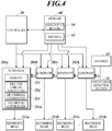
- FIG. 4 is a view showing the configuration for processing of image data.
- Each of the head units 21 of the inkjet recording device 100 is provided with substrates 201a to 201h (also collectively referred to as substrates 201) respectively corresponding to the recording heads 211a to 211h.
- the recording controllers 251 corresponding to respective recording heads 211a to 211h are provided on the respective substrates 201, and the processing operations can be performed in parallel to each other.
- the substrates 201 are respectively provided with memories 253 (first storages). Since the configurations of the substrates 201b to 201h are same as the configuration of the substrate 201a, the description thereof is omitted here.
- Each of the substrates 201 receives input of the drive data (halftone image data) related to the ink ejection from each of the nozzles 27 (associated with each of the nozzles 27) on the basis of the job data 65 stored in the storage 60.
- the drive data is two dimensionally arranged in accordance with the arrangement order in the width direction of the recording element 26 (nozzle 27) and the drive period order of the ink ejection (that is, position in the conveyance direction).
- the drive data is divided in the width direction for each of the recording ranges of the recording heads 211, and sent to the memory 253 of each of the substrates 201. That is, the drive operations of the respective recording heads 211 are independently performed on the basis of the respective separate pieces of data (divided drive data).
- the divided drive data is generated so as to overlap with each other for the portion where the arrangement ranges of nozzle openings 27a (recording ranges of image) overlap with each other in the width direction.
- the entire halftone image data in the conveyance direction (two-dimensional arrangement data divided in the width direction) is sent to the substrate 201, and while a part or all of the image is formed a specified number of times, the data which was sent to the substrate 201 is stored in the memory 253.
- Each of the substrates 201a to 201h stores the ejection failure nozzle list 254 and the meandering information 255 (reference data). Each piece of the meandering information 255 is same as the meandering information 63 stored in the storage 60.
- the ejection failure nozzle list 254 may be same as the ejection failure nozzle list 62 or may be only the list of ejection failure nozzles in each of the recording heads 211a to 211h corresponding to the respective substrates 201a to 201h.
- the ejection failure nozzle list 254 and the meandering information 255 are stored and retained in a volatile memory such as a DRAM (second storage).
- the above corresponding data of the ejection failure nozzle list 254 and meandering information 255 are transmitted from the storage 60, and stored and retained during the operation of the inkjet recording device 100.
- the ejection failure nozzle list 254 and meandering information 255 may be stored continuously in a nonvolatile memory and the like unless the update data is received.
- the detection signals of the conveyance detecting section 41 and the encoder 43 are in cascade connection in series (in chains) to the substrates 201a to 201h, and the detection signals are obtained (input) in synchronization.
- the controller 50 assigns the drive data to one of the recording heads 211. This assignment is performed separately or collectively to the portion which is mechanically assigned to one of the recording heads 211 and to the portion which is assigned at an appropriate ejection distribution rate on the basis of the assignment setting 64. All pieces of drive data corresponding to the nozzles of the recording head 211 to which the drive data was not assigned are set to non-ejection so as not to eject the ink regardless of the original drive data.
- the recording controller 251 performs adjustment so that the image formation is continued at a correct position on the recording medium by shifting (changing) the correspondence relationship between one-dimensional data (line data) in the width direction and the nozzles (recording elements 26) which are arranged in order in the width direction at each drive period (each of the above predetermined timings) of the obtained divided drive data.
- the conveyance belt 14 generates a little meandering according to the accuracy and the like of each of the components such as the drive roller 11.
- the conveyance belt 14 has a little periodical change in the width direction of each position in the rotary movement direction on the conveyance belt 14 when the conveyance belt 14 moves in the rotary movement direction.
- the recording medium can generate a periodical change of position in the width direction on the basis of the meandering of this conveyance belt 14.
- the position of conveyance belt 14 is specified by the detection timing of the origin sign by the conveyance detecting section 41 and the movement amount of the conveyance belt 14 (that is, conveyance movement amount of the recording medium, and movement speed) by the detection signal of encoder 43.
- the phase of this periodical change at a desired position and timing is specified on the basis of the movement information of the recording medium, thereby the meandering information 255 storing this periodical change is referred to (used), and the positional shift amount in the width direction related to the meandering is specified.
- the recording controller 251 shifts the correspondence relationship between the drive data and the nozzles 27 by the amount corresponding to the positional shift amount in the width direction, for each line unit extending in the width direction.
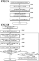
- FIGS. 5A and 5B are flowcharts showing the processing procedures of the drive image.
- FIG. 5A is a flowchart showing the control procedure of drive image division processing by the controller 50.
- FIG. 5B is a flowchart showing the control procedure of drive image output processing by each of the recording controllers 251. These processing is included in an image forming control method in the embodiment.
- the drive image division processing is started after generation of the halftone image as image data for drive in the controller 50.
- the controller 50 obtains the halftone image (step S101).
- the controller 50 sets the recording range (arrangement range of nozzles 27) in each of the substrates 201 to the halftone image (step S102).
- the recording ranges are determined to overlap with each other in the substrates 201 corresponding to the respective recording heads 211 for the above-mentioned overlapping range.
- the controller 50 performs assignment processing of the overlapping range by using the assignment setting 64.
- the controller 50 divides the drive data into the data ranges corresponding to the recording ranges corresponding to the respective substrates 201 so that each range has the above-mentioned overlapping range (after the assignment processing) (step S103; initial setting step).
- the controller 50 outputs the drive data (divided drive data) which was divided to each of the substrates 201 (step S104).
- the controller 50 then ends the drive image division processing.
- the drive image output processing by the recording controller 251 of each of the substrates 201 is started in response to the input of divided drive data to the memory 253.
- the recording controller 251 obtains the divided drive data and reads the obtained data (step S201).
- the recording controller 251 obtains the positional information and speed information of the conveyance belt 14 (collectively, movement information of the recording medium) on the basis of the synchronization signal from the encoder 43 and the like.
- the recording controller 251 obtains the positional shift amount (meandering amount) in the width direction of the recording medium at the position where the ink attaches to the recording medium and at a timing when the ink attaches to the recording medium (which may be generally the ejection timing from each of the nozzles 27), the ink being ejected from each of the nozzles 27 according to the line data (line (raster) data extending in the width direction at the predetermined position in the conveyance direction) which is output to the recording head 211 next (step S202).
- line data line (raster) data extending in the width direction at the predetermined position in the conveyance direction
- the recording controller 251 performs correction of shifting the line data for each of the nozzles 27 (recording elements 26) (that is, correspondence relationship with each of the nozzles 27) for the amount of the number of nozzles corresponding to the obtained positional shift amount (step S203).
- the processing of these steps S202 and S203 forms an adjusting step in the embodiment.
- the recording controller 251 refers to the ejection failure nozzle list 254, and determines whether or not the ink is set to be ejected from the ejection failure nozzle which is set. If the ink is set to be ejected from the ejection failure nozzle, the recording controller 251 performs ejection failure complementary processing of complementing the ejection of the ejection failure nozzle with another nozzle (step S204).
- the recording controller 251 outputs the drive data of the line, to which the above processing was performed, to each of the recording heads 211 a predetermined time before the ejection operation (step S205).
- the recording controller 251 determines whether the output of all the number of lines (total number of lines) of the output target is finished (step S206).
- the total number of lines corresponds to the number of all the lines when a part or all of the divided drive data is output a specified number of times (the output range may be changed for each output time). If it is determined that the output of the total number of lines is finished (step S206; YES), the recording controller 251 ends the drive image output processing. If it is determined that the output of the total number of lines is not finished (step S206; NO), the recording controller 251 determines whether the output of all the lines at the present output is finished (step S207).
- step S207; NO If it is determined that the output of all the lines at the present output is not finished (step S207; NO), the processing of recording controller 251 returns to step S202. If it is determined that the output of all the lines is finished (step S207; YES), the recording controller 251 returns the next output line to the first line of the divided drive data (step S208). Then, the processing of recording controller 251 returns to step S202.
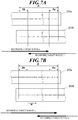
- FIGS. 6A, 6B , 7A and 7B are views for explaining the shift of image data (drive data) in response to the meandering.
- the meandering period L and the amplitude Wm on the spatial structure are determined according to the characteristics, arrangement and the like on the above structure ( FIG. 6A ).
- the periodical change (positional shift) in the width direction of the conveyance belt 14 by these meandering period L and amplitude Wm can be the sum of the component moving in accordance with the rotary movement of the conveyance belt 14 and/or the component vibrating at each position on the conveyance belt 14 (predetermined position in a system of moving in accordance with the rotary movement of the conveyance belt 14).
- the parameter of periodical change according to them is tested and retained in advance.
- the phase of this positional shift is measured and obtained at a predetermined point of time.
- the distance or the like is retained in advance.
- the positional shift amount (for example, value with the nozzle pitch as unit) in each phase in the meandering period L is associated with the phase and/or the position at each predetermined phase interval (or positional interval in the rotary movement direction of the conveyance belt 14), and stored and retained as the meandering information 63, 255.
- the phase at the ink attachment timing at the ink attachment position from the nozzle 27 based on the drive data (line data) is estimated (in the embodiment, specified in a little error range) on the basis of at least a part of the above parameter, the interval between the position Xi which is the ink attachment position and the detection position X0 by the conveyance detecting section 41, the detection result by the conveyance detecting section 41 (conveyance speed, and detection timing of the origin sign O and position in the width direction where the detection result was obtained), and the like.
- the necessary detection contents are determined in advance and can be obtained (in the embodiment, the conveyance speed by the encoder 43 and the above detection result by the conveyance detecting section 41 are obtained).
- the correspondence relationship between the line data and the nozzles 27 is shifted (changed) so as to offset the positional shift amount according to the estimated phase (so that each drive data is associated with the nozzles 27 at the positions according to the positional shift amount).
- the width of each of the regions Da and Db is equal to the amplitude Wm, that is, the maximum value (maximum width) of the positional shift amount, but the width may be larger than the above maximum width in the range of having the total width equal to or less than the width of the overlapping range D (each being equal to or less than half the width of the overlapping range D)).
- the nozzles of the recording head 211a are set not to eject the ink (not to cause the recording elements to perform the recording operation). All the inks for the region Da are set to be ejected from the nozzles of the recording head 211b.
- the nozzles of the recording head 211b are set not to eject the ink (not to cause the recording elements to perform the recording operation). All the inks for the region Db are set to be ejected from the nozzles of the recording head 211a.
- assignment is performed with the assignment setting 64 so that the ink is ejected complementarily from each nozzle 27 of one of the recording heads 211a and 211b as usual.
- the ejection distribution rate which is the rate of assignment to allow the ink ejection is determined to gradually increase as the nozzle is located away from the end of the arrangement range (image recording range).
- the specific method of this assignment may be determined by an appropriate method which is conventionally known.
- the setting not to eject the ink from the nozzles 27 of regions Da and Db is performed separately from the assignment setting 64. However, the setting not to eject the ink may be included in the assignment setting 64.
- the image of the line is recorded at the correct position by determining whether the ink is allowed to be ejected from each of the nozzles 27 as set in the original line data (for example, the ink is allowed to be ejected from the nozzles shown in black in the drawing, whether to actually eject the ink from each nozzle which is allowed to eject the ink is determined by the original drive data (halftone image data), in the overlapping range D, one of the recording heads 211a and 211b is complementarily set to be able to eject the ink).
- the recording target range a and the recording target range b on the recording medium are shifted to the right by the width W with respect to the recording ranges by the recording heads 211a and 211b. If the ink is ejected by the original line data in this state, the recording position on the recording medium of the image on this line is shifted to the left by the width W. Accordingly, in the embodiment, the setting related to whether the ink is allowed to be ejected from each nozzle is shifted to the right by the number of nozzles corresponding to the width W.
- the nozzles located in the region Da of the width nearly equal to the amplitude Wm from the right end of the recording head 211a are set not to eject the ink.
- the drive data for the portion which is set not to eject the ink protrudes from the portion corresponding to the nozzles 27 of the recording head 211a and disappears (part of the drive data is deleted).
- the drive data for the nozzles of the recording heads 211a and 211b in this region Da is shifted from the left (central side of the overlapping range D).
- the complemental ejection is performed, that is, the abnormality such as a missing part is not generated in the formed image.
- the nozzles (a part of drive elements) located in the region Db of the width nearly equal to the amplitude Wm from the left end of the recording head 211b the corresponding drive data does not exist due to the shift.
- the drive data which sets not to eject the ink, is added to each of the nozzles.
- the drive data of nozzles in the region Db in the recording head 211a the data which was originally out of the overlapping range is shifted from the left side.
- all of the inks are ejected from the nozzles 27 in the recording head 211a. Accordingly, also in this region Db, the abnormality such as missing of the ink ejection is not generated.
- a margin (region where the image is not formed) of the width corresponding to the amplitude Wm may be provided on both ends in the width direction of the line head (head unit 21) in advance.
- FIGS. 8A and 8B are views for explaining the complementary operation of the ink ejection failure nozzle.
- the complementary operation is performed for a case where an ejection failure occurs in each nozzle to which the ink ejection was finally assigned after the positions (line data), which are allowed to or not allowed to eject the ink, were shifted according to the meandering.
- the nozzle 27f1 is the ejection failure nozzle, it is not necessary to perform complementary processing on this line since this nozzle 27f1 is originally set not to eject the ink (not allowed to eject the ink).
- the nozzle 27f1 is set to be able to eject the ink.
- the complementary processing is performed not to eject the ink from this nozzle 27f1 and to eject the ink from another nozzle if necessary, that is, in a case where the nozzle 27f1 is actually set to eject the ink according to the original drive data (halftone image data).
- the assignment may be simply changed to the nozzle at the same position in the width direction of the recording head 211b.
- this nozzle 27f2 is necessarily the nozzle which is allowed to eject the ink. Accordingly, in a case where this nozzle 27f2 is actually set to eject the ink, the nozzle 27c2 adjacent to this nozzle 27f2 or the like instead of the nozzle 27f2 is set to eject the ink complementarily.
- the complementary ink ejection from the nozzle 27c2 is not limited to the same timing as the timing when the nozzle 27f2 is originally set to eject the ink, that is, not limited to within the same line data.
- the complementary ink ejection from the nozzle 27c2 may be transferred to the next ink ejection timing, that is, the next line data.
- the inkjet recording device 100 in the embodiment includes: a conveyance section 10 that conveys a recording medium; a detecting section 40 that obtains movement information of the recording medium which is conveyed; a recording operation section 20 that has a plurality of recording elements 26 (including nozzles 27 and electromechanical conversion elements 252) which perform a recording operation; and a controller 50.
- the plurality of recording elements 26 are divided into a plurality of recording heads 211, each of the recording heads 211 having a plurality of recording elements 26.
- the plurality of recording heads 211 perform image formation in respective recording ranges that are different in a width direction which is orthogonal to a movement direction of the conveyed recording medium (rotary movement direction of the conveyance belt 14 in a state in which the recording medium is placed) in a plane parallel to the recording medium. Recording ranges that are adjacent in the width direction among the recording ranges partially overlap in the width direction. Setting is performed to drive data related to the recording operation so that a recording element(s) 26 does not perform the recording operation, the recording element(s) 26 corresponding to a predetermined range from an end in the width direction of the recording range.
- the controller 50 changes (shifts) a correspondence relationship between the drive data and the recording elements 26 so that the drive data, to which the setting is performed and which is associated with each of the drive elements 26, is associated with each of the recording element(s) 26 at position(s) according to a positional shift amount in the width direction of the recording medium, the positional shift amount being obtained based on the movement information for each position in the movement direction (conveyance direction) of the recording medium.
- the predetermined range is determined to be equal to or more than a maximum width (amplitude Wm) of a periodical change of the positional shift amount.
- the data not causing the recording operation in the width which is equal to or more than the amplitude Wm in such a way, in a case where the positional shift within the amplitude Wm is generated, all pieces of drive data losing the corresponding nozzles 27 (recording elements 26) by the shift of the correspondence relationship is the data which does not cause any nozzle to perform the recording operation. That is, the data which causes the recording operation is not missed. Therefore, according to the inkjet recording device 100, the divided drive data which is divided for each of the recording heads 211 is individually processed, and white streaks or the like due to the data missing are not generated. Thus, it is possible to perform the recording operation more easily while suppressing the degradation of image quality.
- the conveyance section 10 has a conveyance belt 14 on which the recording medium is placed.
- the positional shift amount is obtained based on the movement information related to meandering during movement of the conveyance belt 14.
- the placement member on which the recording medium is placed is an endless conveyance belt 14.
- a continuous conveyance belt 14 By conveying the recording medium by using a continuous conveyance belt 14 in such a way, it is possible to stably convey especially a continuous medium.
- the rotary length of the conveyance belt 14 is long and a periodical positional shift such as meandering easily occurs. Accordingly, by performing the correction to the positional shift as mentioned above as needed, it is possible to form a stable image easily and continuously.
- An origin sign O is provided to the conveyance belt 14, and the detecting section 40 (conveyance detecting section 41) obtains the movement information of the recording medium based on a detection result of the origin sign O.
- the meandering period is one over a predetermined number (one divided by a predetermined number) of the conveyance belt length or the like, especially in a case where a positional shift of such a period easily occurs in the continuous conveyance belt 14 or the like, by specifying the position in the rotary movement direction on the conveyance belt 14 with the position of the origin sign O as a reference, it is possible to specify the phase of periodical positional shift easily and accurately.
- the positional shift amount corresponding to the phase is easily specified, the correction corresponding to the positional shift amount is performed rapidly, and thus it is possible to easily suppress the shift of the image forming position and reduce the degradation of image quality.
- the controller 50 When drive data corresponding to a part of the recording elements 26 does not exist by change (shift) of the correspondence relationship between the recording elements 26 (nozzles 27) and the drive data, the controller 50 adds data not causing the part of the recording elements 26 to perform the recording operation as the drive data for the portion not having the drive data (the part of the recording elements 26).
- the drive data causing the recording operation in another overlapping recording head 211 is shifted into the portion losing the drive data.
- the controller 50 deletes the part of the drive data. That is, it is not necessary to transmit the data which protrudes from the drive data of the image forming range of one recording head 211 to the drive data of another recording head 211 which is adjacent in the width direction, and it is sufficient to merely delete the data. Since the drive data out of the image forming range is only the data which does not cause the recording operation, the image missing is not generated. Thus, in the inkjet recording device 100, it is possible to form an appropriate image handling the periodical positional shift (meandering) with simple processing while reducing the degradation of image quality.
- the drive data is stored in the memories 253 for ranges respectively corresponding to the recording ranges of the recording heads 211, and these pieces of data for the respective recording heads 211 are processed in parallel.
- the data is separated in a hardware manner and stored and processed, in the inkjet recording device 100, it is possible to form an image of an appropriate image quality easily at a high speed from the image data related to a long line head without generating problems such as restriction of the processing speed due to the limitation of data transferring speed and the increase in the processing load of the recording controller 251.
- the memories 253 are provided on respective separate substrates 201a to 201h. By completely separating the hardware in such a way, it is possible to perform assembly with each of the recording heads 211 as a set. Thus, the structure can be easily obtained flexibly according to the number of recording heads 211, and the versatility is high. Since the processing is completely independent by the unit of substrate, it is possible to prepare the data with enough time before the actual image formation.
- the inkjet recording device 100 includes a volatile memory such as a DRAM that stores meandering information 255 indicating a pattern of the periodical change of the positional shift amount of the recording medium.
- the controller 50 obtains the positional shift amount based on the movement information by using the meandering information 255.
- the same meandering information 255 is retained so as to correspond to each of the recording heads 211 of each recording operation section 20 (head unit 21). Thus, it is possible to surely avoid the generation of shift of the correction amount between the recording heads 211. Since it becomes easy to generate the meandering information 255 and output the meandering information 255 to each of the substrates 201, the work is not troublesome.
- the controller 50 has recording controllers 251 corresponding to the respective recording heads 211, and the movement information based on the detection result of the detecting section 40 is synchronized and input to the recording controllers 251. That is, since it is possible to align the timings of parallel processing of the data respectively corresponding to the plurality of recording heads 211, it is possible to perform the correction of positional shift related to the meandering with a same reference easily and appropriately without complicating the timing control of the processing. Thus, in the inkjet recording device 100, it is possible to prevent the distortion of raster image, data missing and the like of each line, and stably and continuously form an image which does not have the distortion or color shift.
- the detecting section 40 has an encoder 43 that measures a movement amount (conveyance movement amount) in the conveyance direction of the conveyance belt 14 by the conveyance section 10.
- a movement amount conveyance movement amount
- By detecting the rotation mount of the drive roller 11 or the like it is possible to accurately obtain the position of recording medium and the conveyance speed in real time.
- the inkjet recording device 100 includes a plurality of recording operation sections 20, each of the recording operation sections being the above recording operation section 20.
- the plurality of recording operation sections 20 are arranged at positions that are different in the movement direction of the conveyed recording medium, and at least a part of the recording operation sections 20 perform(s) the recording operation with a color(s) different from a color(s) of the recording operation section(s) 20 other than the part of the recording operation sections 20, and the color image can be output.
- the positional shift (color shift) between the colors appear in a systematic manner and easily becomes noticeable if there is such a large periodical positional shift which is equal to or more than the interval of the plurality of head units 21 as corresponding to the rotary length of the conveyance belt 14.
- even a slight color shift easily becomes noticeable depending on the texture in the fabric, the degradation of image quality is effectively suppressed with easy processing.
- the image forming control method in the embodiment includes: an initial setting step that is performing setting to drive data related to a recording operation so that a recording element does not perform a recording operation, the recording element corresponding to a predetermined range from an end in a width direction in a recording range; and an adjusting step that is changing, for each of the recording heads 211, a correspondence relationship between the drive data and a recording element so that the drive data, which is associated with each drive element 26, is associated with each of the recording elements 26 at positions according to a positional shift amount in a width direction of a recording medium, the positional shift amount being obtained based on the movement information for each position in the movement direction (conveyance direction) of the recording medium.
- the predetermined range is determined to be equal to or more than the maximum width of a periodical change of the positional shift amount.
- the substrate 201 is provided to each of the recording heads 211 as a unit, and the drive data is separately stored and processed.
- the drive data may be stored and processed by the head module as a unit (element group).
- the conveyance detecting section 41 may detect not only the origin sign O but also the position in the width direction of a reference line in the conveyance direction of the conveyance belt 14. By obtaining this position, it is possible to measure the positional shift amount in the width direction of the conveyance belt 14 in real time.
- the information on this positional shift amount is sent to each of the recording controllers 251.
- Each of the recording controllers 251 specifies the positional shift amount of the recording medium which is assumed at a predetermined timing, and shifts the image data in accordance with the positional shift amount. In a case where the positional shift amount of the recording medium is obtained directly or indirectly in real time, the meandering information 255 may not be used.
- the signal of encoder 43 is obtained to specify the accurate conveyance speed.
- the conveyance speed may be fixed without obtaining the value of encoder 43, and the phase shift amount may be corrected periodically (approximately one period of the conveyance belt 14, for example) by the detection result of the conveyance detecting section 41 or the like.
- meanderings of a plurality of periods may overlap.
- the proportion between the plurality of periods is an integer or the like, it is sufficient that the meandering information 63, 255 is generated on the basis of a long period.
- the meandering information may be separately generated and added. That is, the entire change amount combining the individual periodical changes may not be completely and periodically repeated.
- the memory 253 and the recording controller 251a are completely separated in each of the substrates in a hardware manner.
- the memory 253 and the recording controller 251a may not be completely divided in a hardware manner.
- the data related to the plurality of recording heads 211 may be stored and processed on a single substrate. Even in a case where the memory 253 and the recording controller 251a are divided in a hardware manner, the memories 253 and the recording controllers 251 a may not be provided on different substrates 201. Even in these cases, the processing of data related to the overlapping range D of adjacent recording heads 211 is not complicated, and it is possible to perform the recording operation more easily while suppressing the degradation of image quality.
- the same meandering information 255 is stored in different substrates 201a to 201h.
- different meandering information 255 having a different phase according to the difference in position in the conveyance direction of each of the recording heads arranged in a staggered manner or the like may be stored.
- meandering information 255 of a different phase may be stored according to the position in the conveyance direction.
- the endless conveyance belt 14 is used.
- the placement member on which the recording medium is placed does not need to be endless.
- the placement member may be other members which possibly generate meandering such as a member which is provided intermittently.
- the generation factor, generation range and the like of the meandering are not limited as long as the periodical positional shift amount in the width direction is a pattern which can be specified (estimated) in advance in a range facing the ink attachment position from the head unit 21.
- the signals from the conveyance detecting section 41 and the encoder 43 are synchronized and transmitted to the recording controllers 251 via a signal line which connects the substrates 201 in cascade connection.
- the cascade connection is not necessary as long as the synchronization and parallel input are possible.
- an inkjet recording device 100 which has a plurality of head units 21 at different positions in the conveyance direction (rotary movement direction of the conveyance belt 14), and ejects inks of different colors.
- One or a plurality of head units 21 may eject only the ink of a single color.
- the recording medium is paper medium or the like
- the embodiment has been described by taking, as an example, an inkjet recording device which includes multiple sets as recording elements, each of the sets being a set of nozzle 27 and electromechanical conversion element 252 corresponding to the nozzle 27.
- the present invention is not limited to this as long as the device has a line head structure in which the multiple recording elements are arranged so as to be divided into a plurality of recording heads (head modules, element groups), and the arrangement ranges of recording elements (recording ranges) in the respective element groups partially overlap.
- the present invention may be applied to an LED printer using LED elements.
Landscapes
- Engineering & Computer Science (AREA)
- Quality & Reliability (AREA)
- Ink Jet (AREA)
- Particle Formation And Scattering Control In Inkjet Printers (AREA)
Abstract
An image forming device (100) and an image forming control method of the image forming device including: a conveyance section (10); an obtaining section (40); a recording operation section (20) having recording elements (26); and a controller (50, 251), wherein the recording elements are divided into element groups (211), which perform image formation in recording ranges different in a width direction, recording ranges adjacent in the width direction partially overlap, drive data is set so that a recording element corresponding to a predetermined range (Da, Db) from an end in the width direction in each recording range does not perform the recording operation, for each element group, the controller changes a correspondence relationship between the drive data and the recording elements so that the drive data associated with each drive element (26) is associated with each recording element at positions according to a positional shift amount (W) in the width direction of the recording medium, which is obtained based on movement information for each position in the movement direction, and the predetermined range is determined to be equal to or more than a maximum width (Wm) of a periodical change of the positional shift amount.
Description
- The present invention relates to an image forming device and an image forming control method.
- There are image forming devices each of which causes multiple nozzles to eject ink to make the ink attach onto a recording medium and records an image (including three-dimensional structures, film formation not having colors, and the like) on the recording medium. Such image forming devices include a single pass type image forming device which records an image without performing scanning of nozzles by moving the recording medium relative to the nozzles in a predetermined direction and arranging the nozzles over the recordable width of the recording medium in a width direction crossing the predetermined direction, in order to meet the requirements of high speed and high accuracy.
- As for the single pass type image forming device, there is known a technique of using line heads arranging nozzles over the recordable width by arranging a plurality of blocks (element groups) in a width direction, each of the blocks arranging a plurality of nozzles. However, this case has a problem that it is difficult to sufficiently suppress the shift of relative positions between the blocks at the time of assembly. With respect to this,
JP 2009-51066A - However, there is a case where the image recording medium does not move accurately straight in the desired direction, periodical positional shift in the width direction occurs and the image quality is degraded, depending on the conveyance accuracy of the conveyance section which conveys the recording medium. When the image forming positions are corrected in response to this positional shift, the conventional techniques cannot suppress the degradation of image quality since the data corresponding to each of the blocks is not sufficient or goes out and cannot be recorded. On the other hand, there has been a problem that transmitting data between the blocks is troublesome.
- An object of the present invention is to provide an image forming device and an image forming control method which can suppress the degradation of image quality and perform the recording operation more easily.
- To achieve at least one of the abovementioned objects, according to an aspect of the present invention, an image forming device reflecting one aspect of the present invention includes: a conveyance section that conveys a recording medium; an obtaining section that obtains movement information of the recording medium which is conveyed; a recording operation section that has a plurality of recording elements which perform a recording operation; and a controller. The plurality of recording elements are divided into a plurality of element groups, each of the element groups having a plurality of recording elements, the plurality of element groups perform image formation in respective recording ranges that are different in a width direction which is orthogonal to a movement direction of the conveyed recording medium in a plane parallel to the recording medium, recording ranges that are adjacent in the width direction among the recording ranges partially overlap in the width direction, setting is performed to drive data related to the recording operation so that a recording element does not perform the recording operation, the recording element corresponding to a predetermined range from an end in the width direction in each of the recording ranges, for each of the element groups, the controller changes a correspondence relationship between the drive data and the recording elements so that the drive data, to which the setting is performed and which is associated with each drive element, is associated with each of the recording elements at positions according to a positional shift amount in the width direction of the recording medium, the positional shift amount being obtained based on the movement information for each position in the movement direction, and the predetermined range is determined to be equal to or more than a maximum width of a periodical change of the positional shift amount.
- In the image forming device, the conveyance section has a placement member on which the recording medium is placed, and the positional shift amount is obtained based on the movement information related to meandering during movement of the placement member.
- In the image forming device, the placement member is an endless belt.
- In the image forming device, an index indicating a reference position is provided to the placement member, and the obtaining section obtains the movement information of the recording medium based on a detection result of the index.
- In the image forming device, when drive data corresponding to a part of the recording elements does not exist by change of the correspondence relationship, the controller adds data not causing the part of the recording elements to perform the recording operation as the drive data corresponding to the part of the recording elements.
- In the image forming device, when a recording element corresponding to part of the drive data does not exist by change of the correspondence relationship, the controller deletes the part of the drive data.
- The image forming device includes a plurality of first storages corresponding to the respective element groups, wherein the drive data is stored in the plurality of first storages for ranges respectively corresponding to the recording ranges of the element groups, and the drive data is processed in parallel.
- In the image forming device, the first storages are provided on respective separate substrates.
- The image forming device includes a second storage that stores reference data indicating a pattern of the periodical change of the positional shift amount, wherein the controller obtains the positional shift amount based on the movement information by using the reference data.
- In the image forming device, the same reference data is retained so as to correspond to each of the element groups of the recording operation section.
- In the image forming device, the controller has individual controllers corresponding to the respective element groups, and the movement information is synchronized and input to the individual controllers.
- In the image forming device, the obtaining section has an encoder that measures a conveyance movement amount by the conveyance section.
- The image forming device includes a plurality of recording operation sections, each of the recording operation sections being the recording operation section, wherein the plurality of recording operation sections are arranged at positions that are different in the movement direction of the conveyed recording medium, and at least a part of the recording operation sections performs the recording operation with a color different from a color of a recording operation section other than the part of the recording operation sections.
- To achieve at least one of the abovementioned objects, according to another aspect of the present invention, an image forming control method reflecting one aspect of the present invention is an image forming control method of an image forming device including: a conveyance section that conveys a recording medium; an obtaining section that obtains movement information of the recording medium which is conveyed; and a recording operation section that has a plurality of recording elements which perform a recording operation, wherein the plurality of recording elements are divided into a plurality of element groups, each of the element groups having a plurality of recording elements, the plurality of element groups perform image formation in respective recording ranges that are different in a width direction which is orthogonal to a movement direction of the conveyed recording medium in a plane parallel to the recording medium, and recording ranges that are adjacent in the width direction among the recording ranges partially overlap in the width direction, the image forming control method including: an initial setting step that is performing setting to drive data related to the recording operation so that a recording element does not perform the recording operation, the recording element corresponding to a predetermined range from an end in the width direction in each of the recording ranges; and an adjusting step that is changing, for each of the element groups, a correspondence relationship between the drive data and the recording elements so that the drive data, to which the setting is performed and which is associated with each drive element, is associated with each of the recording elements at positions according to a positional shift amount in the width direction of the recording medium, the positional shift amount being obtained based on the movement information for each position in the movement direction, wherein the predetermined range is determined to be equal to or more than a maximum width of a periodical change of the positional shift amount.
- The advantages and features provided by one or more embodiments of the invention will become more fully understood from the detailed description given hereinbelow and the appended drawings which are given by way of illustration only, and thus are no intended as a definition of the limits of the present invention, wherein:
-
FIG. 1 is an entire perspective view of an inkjet recording device which is an embodiment of an image forming device of the present invention; -
FIG. 2 is a bottom view showing a surface facing a conveyance surface of a head unit; -
FIG. 3 is a block diagram showing the functional configuration of the inkjet recording device; -
FIG. 4 is a view showing the configuration related to processing of image data; -
FIG. 5A is a flowchart showing a procedure of drive image division processing; -
FIG. 5B is a flowchart showing a procedure of drive image output processing; -
FIG. 6A is a view for explaining a shift of image data in response to meandering; -
FIG. 6B is a view for explaining a shift of image data in response to meandering; -
FIG. 7A is a view for explaining a shift of image data in response to meandering; -
FIG. 7B is a view for explaining a shift of image data in response to meandering; -
FIG. 8A is a view for explaining a complementary operation of the ink ejection failure nozzle; and -
FIG. 8B is a view for explaining a complementary operation of the ink ejection failure nozzle. - An embodiment of the present invention will be described on the basis of the drawings. However, the scope of the invention is not limited to the disclosed embodiments.
-
FIG. 1 is the entire perspective view of aninkjet recording device 100 which is the embodiment of an image forming device of the present invention. - The
inkjet recording device 100 has a plurality of, eight in the embodiment, line heads, and can perform recording of a color image by ejecting the ink with the single pass method. Theinkjet recording device 100 includes: aconveyance section 10;recording operation sections 20; anink supplying section 30; aconveyance detecting section 41; animage detecting section 42, and the like. - The
conveyance section 10 includes: adrive roller 11; aconveyance driving section 12, a conveyance belt 14 (placement member); and the like. Theconveyance driving section 12 has a rotation motor which causes thedrive roller 11 to perform a rotation operation at a predetermined speed. Theconveyance belt 14, which is endless, is wound around thedrive roller 11 in addition to following rollers not shown in the drawings, and theconveyance belt 14 performs a rotary movement by the rotation of thedrive roller 11. With the outer surface of thisconveyance belt 14 as the conveyance surface, theconveyance section 10 places the recording medium in a predetermined range on the conveyance surface, and conveys the recording medium in the rotary movement direction (movement direction of the recording medium at the time of conveyance, that is, conveyance direction) in accordance with the rotary movement of theconveyance belt 14. Though the type of the recording medium is not especially limited, the recording medium in the embodiment is a continuous fabric or the like. For example, a roll type fabric is sequentially rolled out to be placed on the conveyance surface, and can be conveyed. - Each of the
recording operation sections 20 includes acarriage 22, acarriage elevation section 23, and the like. A set number (eight, in the embodiment) of therecording operation sections 20 are provided (a plurality ofrecording operation sections 20 are provided), the set number corresponding to the color number of inks. Each of thecarriages 22 is arranged above (in the height direction) the conveyance surface of the recording medium by theconveyance section 10 so as to extend in a direction crossing the conveyance direction of the conveyance by theconveyance section 10, which is the width direction orthogonal to the conveyance direction in the embodiment, in the plane parallel to the conveyance surface. A head unit 21 (seeFIG. 2 ; line head) is fixed to each of thecarriages 22 so as to be able to eject the ink droplets from the openings of nozzles (nozzle openings 27a; seeFIG. 2 ) over the entire width (recordable width in the width direction, a little margin may be provided to both ends or one end) of the recording medium which is conveyed. The number (two or more) of the recording elements 26 (seeFIG. 3 ), which are nozzles here, the ink flow paths (ink chambers) and the structures to eject the ink from the respective nozzles (after-mentionedelectromechanical conversion elements 252; seeFIG. 3 ), which are included in each of the eight (a plurality of)head units 21, may be determined as needed according to the recording resolution, the size of the recording medium which can be recorded by theinkjet recording device 100, and the like. The plurality ofcarriages 22, that is, therecording operation sections 20 are provided at positions which are different from each other in the conveyance direction. Each of thecarriages 22 is provided so as to be able to change the position in the height direction by thecarriage elevation section 23, and the distance from the conveyance surface to thehead unit 21 is changed in accordance with the movement of thecarriage 22. The ink is ejected from the nozzles by therecording elements 26 performing the recording operation (ejecting the ink), and thereby an image is recorded (formed) on the recording medium. - The
carriage elevation section 23 changes the distance of thecarriage 22 from the conveyance surface. Thecarriage elevation section 23 includeselevation motors 232,electromagnetic brakes 233,beam members 234, supportingsections 235, and the like. - Two
beam members 234 are provided in nearly parallel in the direction crossing the conveyance direction (orthogonal to the conveyance direction in the embodiment, that is, width direction) above the conveyance belt 14 (conveyance surface side of the recording medium). The supportingsections 235 are respectively fixed to both of the ends of thebeam members 234. Theelevation motors 232, theelectromagnetic brakes 233 and thecarriage 22 are attached to the supportingsections 235. - The
carriage 22 is positioned by moving up or down in accordance with the operations of theelevation motors 232 andelectromagnetic brakes 233 which are driven on the basis of the control signal from the controller 50 (seeFIG. 3 ). - The
elevation motors 232 move thecarriage 22 at a predetermined elevation speed. As theelevation motors 232, for example, servomotors or stepping motors are used. - The
electromagnetic brakes 233 maintain the fixed state of thecarriage 22. The fixed state is released according to the drive signal, and thereby the movement of thecarriage 22 by theelevation motors 232 becomes possible temporarily. That is, in a normal state including the time of disconnection of the power supply, theelectromagnetic brakes 233 fix thecarriage 22. As theelectromagnetic brakes 233, for example, disc brakes are used. - The
ink supplying section 30 contains inks of respective colors used in the image formation, and supplies the inks to thehead units 21. In the embodiment,ink storing tanks 31 of the respective colors are arranged in adedicated rack 32, and connected to thehead units 21 which eject the inks of the respective colors via a piping such as a tube. The inks of the respective colors are not especially limited. However, in the embodiment, the colors of the inks are eight colors which are different from each other, and include C (cyan), M (magenta), Y (yellow) and K (black). For example, inks of P (pink), S (sky), G (gray) and O (orange) (at least a part of the inks is an ink(s) of a color(s) different from the ink(s) other than the part of the inks) can be further supplied. The inks of the respective colors are ejected as respective minute dots and attached to the recording medium by the nozzles of thehead units 21 to which the respective inks were supplied. A mixed color image expressed by the densities corresponding to the number of minute dots, the size of dots (droplet amount) and the like and a combination thereof is formed. The colors of inks which are stored in theink storing tank 31 and supplied to thehead units 21 may be exchangeable. - The
conveyance detecting section 41 is located on the upstream side in the conveyance direction of therecording operation sections 20, and detects an origin sign O of the conveyance belt 14 (index indicating the reference position; seeFIG. 6 ), and outputs the detection signal. The origin sign O is provided at a specific position in the rotary movement direction at a predetermined distance from an end in the width direction of theendless conveyance belt 14. Theconveyance detecting section 41 detects the origin sign O for each rotation of theconveyance belt 14, and outputs the timing. If necessary, theconveyance detecting section 41 may be able to measure and output the position in the width direction of the origin sign O (which may be a relative position from the reference position). The origin sign O may be a sign of a color different from the color of the other portion or may be a hole provided in theconveyance belt 14, for example. Theconveyance detecting section 41 may be a sensor which reads the origin sign O or obtains the detected intensity of the reflected light. In a case where a hole part is provided as the origin sign O, theconveyance detecting section 41 may be a through-beam type light sensor or the like which penetrates the hole part and detects the incident light on the opposite side. The light is not limited to visible light, and may be infrared light and the like. Theconveyance detecting section 41 may be able to directly detect and identify the position (end) or the like in the width direction of the recording medium. - The
image detecting section 42 is provided on the downstream side in the conveyance direction of therecording operation sections 20, and images and reads the surface of the recording medium on which an image was formed by the recording operation sections 20 (or which passed without image formation). Theimage detecting section 42 may include a lighting part not shown in the drawings. The lighting part irradiates the surface to be imaged by the image detecting section 42 (surface of recording medium) nearly evenly. - The
image detecting section 42 includes a one dimensional imaging sensor, for example. In the one dimensional imaging sensor in the embodiment, a plurality of imaging elements are arranged at least over the width of theconveyance belt 14 in the width direction. The recording medium is moved in the conveyance direction by the operation of theconveyance section 10, and thereby theimage detecting section 42 can perform two dimensional imaging on the recording medium. As the imaging sensor, the CCD sensor (Charge Coupled Device), the CMOS sensor (Complementary Metal Oxide Semiconductor) and the like are used. Each of these imaging sensors performs, with the imaging elements, the imaging operation of outputting the electric charge amount and the voltage corresponding to the light amount input to the light receiving element from the surface of the recording medium via an optical system (lens). In the embodiment, the imaging sensor can perform imaging at each wavelength band (a plurality of wavelength bands) of RGB, and the color read image can be obtained by theimage detecting section 42. Theimage detecting section 42 may be used to specify after-mentionedmeandering information - The
conveyance detecting section 41 and theimage detecting section 42 may be able to change the distance from the conveyance surface similarly to thecarriage 22. -
FIG. 2 is a bottom surface view showing the surface facing the conveyance surface in thehead unit 21. - Since each of the
head units 21 has a same shape and a same configuration, the description here will be made for any arbitrary one of thehead units 21. - In the embodiment, eight
recording heads 211a to 211h (element groups; hereinafter, a part or all of the recording heads are also collectively described as the recording heads 211) are fixed to thehead unit 21. On the bottom surface of each of the recording heads 211, there is provided a nozzle array in whichnozzle openings 27a of a plurality ofnozzles 27 are arrayed in the width direction at a predetermined nozzle pitch. The positions ofnozzle openings 27a may be different in the conveyance direction as long as thenozzle openings 27a are arrayed at a predetermined interval in the width direction. The number and size ofnozzle openings 27a shown in this drawing is shown for explanation, and the number ofnozzle openings 27a is actually larger than the number shown in the drawing, and the size of thenozzle openings 27a is sufficiently small compared to the width of the arrangement range in the width direction of thenozzle openings 27a. - The eight recording heads 211 included in one
head unit 21 are arranged in a staggered manner at different positions. In accordance with this, the arrangement ranges in the width direction ofnozzle openings 27a in the respective recording heads 211 are located at positions different from each other, and the image formation can be performed in recording ranges different from each other according to these arrangement ranges. The ends of the arrangement ranges in the width direction of thenozzle openings 27a in adjacent recording heads 211 (that is, recording ranges by the recording heads 211) are a little overlapping with each other. Accordingly, thehead unit 21 is configured to be able to eject the ink from the plurality of nozzles which are divided into each of the recording heads 211 at the above nozzle pitch over the entire width (both ends may have a little margin) of the recording medium M in the width direction by combination of the recording ranges in the width direction of the respective eight recording heads 211. -
FIG. 3 is a block diagram showing the functional configuration of theinkjet recording device 100. - The
inkjet recording device 100 includes theconveyance section 10, therecording operation sections 20, the detecting section 40 (obtaining section), acontroller 50, astorage 60, a communicatingsection 70, adisplay 81, anoperation receiving section 82, abus 90 and the like. Theconveyance section 10 has the above-mentionedconveyance driving section 12. The detectingsection 40 includes the above-mentionedconveyance detecting section 41 and theimage detecting section 42. - Each of the
recording operation sections 20 includes acarriage driving section 24, ahead driving section 25, and the like. Thecarriage driving section 24 outputs a drive signal to the above-mentionedelevation motor 232, theelectromagnetic brake 233 and the like, and operates or fixes them. As mentioned above, theelectromechanical conversion element 252 and thenozzle 27 are included in therecording element 26. - The
head driving section 25 includes a recording controller 251 (individual controller). Therecording controller 251 outputs a drive signal causing the pressure change of the ink in the ink flow path communicated with each of thenozzles 27 in the recording head 211 on the basis of the control of thecontroller 50. As the configuration causing the pressure change, for example, the electromechanical conversion element 252 (in the embodiment, piezoelectric element) is used. Theelectromechanical conversion element 252 causes deformation according to the applied voltage, that is, the output voltage of the drive signal, and thereby deforms the ink flow path, especially the pressure chamber, the pressure chamber being formed by determining the size and shape for causing the pressure change appropriately. As the drive signal, one or a plurality of voltage waveform patterns are determined in advance, whether to output the drive signal in the voltage waveform pattern to theelectromechanical conversion element 252 corresponding to each of the nozzles is determined according to the control signal and drive data (halftone image data) from thecontroller 50. The ink which was pushed out from thenozzle opening 27a by the deformation operation of the electromechanical conversion element 252 (recording operation of the recording element 26) by the drive signal is separated from the ink in the ink flow path by an appropriate amount, and ejected as ink droplets. The output period of the drive signal may be fixed at a single period, or minute adjustment may be allowed. Alternatively, the output period of the drive signal may be determined to be changeable according to the conveyance speed of the recording medium by theconveyance section 10 and the resolution in the conveyance direction of the image. - The
recording controller 251 in the embodiment is provided so as to correspond to each of the plurality of (eight) recording heads 211, and independently operates on the basis of the synchronization signal from anencoder 43 and theconveyance detecting section 41. Therecording controller 251 controls the recording operation of each of the recording heads 211 at the output period of the drive signal on the basis of the drive data of the image range to be recorded by the nozzles of the corresponding recording head 211. - The
controller 50 and therecording controller 251 are included in a controller in the embodiment of the present invention. - The detecting
section 40 has anencoder 43 in addition to the above-mentionedconveyance detecting section 41 and theimage detecting section 42. Theencoder 43 detects the rotation of drive motor or driveroller 11 of theconveyance driving section 12, and outputs a signal corresponding to the rotation direction for each rotation of a predetermined angle. The interval from the previous signal output indicates the rotation speed, that is, the conveyance speed of the recording medium. The position in the rotation direction of theconveyance belt 14 and the position of the recording medium which is conveyed are specified by the detection timing of the origin sign by theconveyance detecting section 41 and the number of signal outputs from theencoder 43. The detection signal of theconveyance detecting section 41 and the signal for each predetermined angle of theencoder 43 and the like are obtained as movement information of theconveyance belt 14 and the recording medium which is placed on theconveyance belt 14. - The
controller 50 integrally controls the entire operation of theinkjet recording device 100. Thecontroller 50 includes a CPU 51 (Central Processing Unit), a RAM 52 (Random Access Memory) and the like. Thecontroller 50 performs various types of processing for image formation based on the image data, status signal and clock signal of each component. Thecontroller 50 performs operation adjustment of the ink ejection from each of thenozzles 27 and the like, detection of the failure state of the ejection operation and processing to treat the failure, and processing such as detection and adjustment of degradation of image quality. - The
CPU 51 is a hardware processor which performs various types of arithmetic processing, and performs control of conveyance of the recording medium, supply of the ink, ejection of the ink, the reading operation of the formed image and the like. TheCPU 51 performs calculation and control for each of the above processing in accordance with the program which was read from thestorage 60. - The
RAM 52 provides a working memory space to theCPU 51 and stores temporary data. The storage region of temporary data may be divided into theRAM 52 and the DRAM region of thestorage 60 as needed. - The
storage 60 stores theprogram 61, various types of setting data, andjob data 65 for image forming instruction, and the like. Thejob data 65 includes recording target image data, the processed data of the recording target image data, information for operation setting, and the like. Theprogram 61 includes a specification program of ejection failure nozzle generating the ink ejection failure, various types of image processing programs, an assignment setting program in the overlapping range of the arrangement ranges ofnozzles 27 in the recording heads 211, and the like. The setting data includes an ejectionfailure nozzle list 62 indicating the positions of nozzles (ejection failure nozzles) generating the ejection failure of the ink, meanderinginformation 63 indicating the change pattern of periodical positional shift amount in the width direction of the recording medium, an assignment setting 64 indicating the selection pattern of nozzles which can eject the ink in the overlapping range in adjacent recording heads 211, and the like. A plurality of pieces of meanderinginformation 63 may be retained according to the mode of meandering appearing in theinkjet recording device 100, the setting value of parameters to depend on, and the like. - The
storage 60 in the embodiment includes a volatile memory such as a DRAM and a nonvolatile memory. The temporary data such as job data and processing data is stored in the volatile memory and processed at a high speed. The temporary data may be deleted after the image recording operation is finished. The programs, setting data and the like are retained by the nonvolatile memory, and are retained even while the electric power is not supplied to theinkjet recording device 100. A part of the programs and setting data, for example, initial data and a basic program may be stored in a ROM or the like which cannot be deleted or rewritten instead of the nonvolatile memory. - The communicating
section 70 is a communication interface which controls the communication operation with external equipment. The communication interface includes, for example, one or a plurality of network cards corresponding to various communication protocols such as a LAN card. On the basis of the control by thecontroller 50, the communicatingsection 70 can obtain image data of the recording target from the external equipment and job data including the setting for image formation, and transmit status information and the like to the external equipment. - The
display 81 displays the status of theinkjet recording device 100, the operation menu and the like on the display screen according to the control signal from thecontroller 50. As the display screen, a liquid crystal screen or the like is used, for example. Thedisplay 81 may include an LED lamp or the like which provides an alarm regarding whether or not the electric power is supplied and/or errors. - The
operation receiving section 82 receives user's operation and outputs to thecontroller 50. Theoperation receiving section 82 has a touch sensor or the like, for example. The touch sensor may be provided to be superposed on the display screen of thedisplay 81 and used as a touch panel. Thecontroller 50 outputs the information on the position and type of the touch operation which was detected by the touch sensor to thecontroller 50. Theoperation receiving section 82 may have a push button switch and/or a keypad. - The
bus 90 is a path which electrically connects thecontroller 50 and each configuration which transmits/receives a signal to/from thecontroller 50, and transmits the signal. - Next, the flow and processing of image data will be described more specifically.
-
FIG. 4 is a view showing the configuration for processing of image data. - Each of the
head units 21 of theinkjet recording device 100 is provided withsubstrates 201a to 201h (also collectively referred to as substrates 201) respectively corresponding to therecording heads 211a to 211h. As mentioned above, therecording controllers 251 corresponding torespective recording heads 211a to 211h are provided on the respective substrates 201, and the processing operations can be performed in parallel to each other. The substrates 201 are respectively provided with memories 253 (first storages). Since the configurations of the substrates 201b to 201h are same as the configuration of thesubstrate 201a, the description thereof is omitted here. - Each of the substrates 201 receives input of the drive data (halftone image data) related to the ink ejection from each of the nozzles 27 (associated with each of the nozzles 27) on the basis of the
job data 65 stored in thestorage 60. The drive data is two dimensionally arranged in accordance with the arrangement order in the width direction of the recording element 26 (nozzle 27) and the drive period order of the ink ejection (that is, position in the conveyance direction). The drive data is divided in the width direction for each of the recording ranges of the recording heads 211, and sent to thememory 253 of each of the substrates 201. That is, the drive operations of the respective recording heads 211 are independently performed on the basis of the respective separate pieces of data (divided drive data). The divided drive data is generated so as to overlap with each other for the portion where the arrangement ranges ofnozzle openings 27a (recording ranges of image) overlap with each other in the width direction. In the embodiment, the entire halftone image data in the conveyance direction (two-dimensional arrangement data divided in the width direction) is sent to the substrate 201, and while a part or all of the image is formed a specified number of times, the data which was sent to the substrate 201 is stored in thememory 253. - Each of the
substrates 201a to 201h stores the ejectionfailure nozzle list 254 and the meandering information 255 (reference data). Each piece of themeandering information 255 is same as the meanderinginformation 63 stored in thestorage 60. The ejectionfailure nozzle list 254 may be same as the ejectionfailure nozzle list 62 or may be only the list of ejection failure nozzles in each of therecording heads 211a to 211h corresponding to therespective substrates 201a to 201h. In the embodiment, the ejectionfailure nozzle list 254 and themeandering information 255 are stored and retained in a volatile memory such as a DRAM (second storage). Each time theinkjet recording device 100 is activated and each time an update is requested explicitly, the above corresponding data of the ejectionfailure nozzle list 254 andmeandering information 255 are transmitted from thestorage 60, and stored and retained during the operation of theinkjet recording device 100. Alternatively, the ejectionfailure nozzle list 254 andmeandering information 255 may be stored continuously in a nonvolatile memory and the like unless the update data is received. - The detection signals of the
conveyance detecting section 41 and theencoder 43 are in cascade connection in series (in chains) to thesubstrates 201a to 201h, and the detection signals are obtained (input) in synchronization. - When the drive data is divided, as for the overlapping range in the width direction of the arrangement ranges (recording ranges of formed image) of
nozzles 27 in adjacent recording heads 211, thecontroller 50 assigns the drive data to one of the recording heads 211. This assignment is performed separately or collectively to the portion which is mechanically assigned to one of the recording heads 211 and to the portion which is assigned at an appropriate ejection distribution rate on the basis of the assignment setting 64. All pieces of drive data corresponding to the nozzles of the recording head 211 to which the drive data was not assigned are set to non-ejection so as not to eject the ink regardless of the original drive data. - In each of the substrates 201, according to the meandering (periodical positional shift in the width direction) of the recording medium, the
recording controller 251 performs adjustment so that the image formation is continued at a correct position on the recording medium by shifting (changing) the correspondence relationship between one-dimensional data (line data) in the width direction and the nozzles (recording elements 26) which are arranged in order in the width direction at each drive period (each of the above predetermined timings) of the obtained divided drive data. Theconveyance belt 14 generates a little meandering according to the accuracy and the like of each of the components such as thedrive roller 11. That is, theconveyance belt 14 has a little periodical change in the width direction of each position in the rotary movement direction on theconveyance belt 14 when theconveyance belt 14 moves in the rotary movement direction. The recording medium can generate a periodical change of position in the width direction on the basis of the meandering of thisconveyance belt 14. In each of thesubstrates 201a to 201h, the position ofconveyance belt 14 is specified by the detection timing of the origin sign by theconveyance detecting section 41 and the movement amount of the conveyance belt 14 (that is, conveyance movement amount of the recording medium, and movement speed) by the detection signal ofencoder 43. The phase of this periodical change at a desired position and timing is specified on the basis of the movement information of the recording medium, thereby the meanderinginformation 255 storing this periodical change is referred to (used), and the positional shift amount in the width direction related to the meandering is specified. Therecording controller 251 shifts the correspondence relationship between the drive data and thenozzles 27 by the amount corresponding to the positional shift amount in the width direction, for each line unit extending in the width direction. - Thereafter, complementary processing of distributing the ink ejection, which is assigned to the ejection failure nozzle, to a nozzle around the ejection failure nozzle on the basis of the ejection
failure nozzle list 62. The drive data after complementary processing is sent to therecording head 211a at an appropriate timing according to the clock signal, and causes theelectromechanical conversion elements 252 to perform the deformation operation. -
FIGS. 5A and 5B are flowcharts showing the processing procedures of the drive image. -
FIG. 5A is a flowchart showing the control procedure of drive image division processing by thecontroller 50.FIG. 5B is a flowchart showing the control procedure of drive image output processing by each of therecording controllers 251. These processing is included in an image forming control method in the embodiment. - The drive image division processing is started after generation of the halftone image as image data for drive in the
controller 50. Thecontroller 50 obtains the halftone image (step S101). Thecontroller 50 sets the recording range (arrangement range of nozzles 27) in each of the substrates 201 to the halftone image (step S102). The recording ranges are determined to overlap with each other in the substrates 201 corresponding to the respective recording heads 211 for the above-mentioned overlapping range. - The
controller 50 performs assignment processing of the overlapping range by using the assignment setting 64. Thecontroller 50 divides the drive data into the data ranges corresponding to the recording ranges corresponding to the respective substrates 201 so that each range has the above-mentioned overlapping range (after the assignment processing) (step S103; initial setting step). Thecontroller 50 outputs the drive data (divided drive data) which was divided to each of the substrates 201 (step S104). Thecontroller 50 then ends the drive image division processing. - The drive image output processing by the
recording controller 251 of each of the substrates 201 is started in response to the input of divided drive data to thememory 253. Therecording controller 251 obtains the divided drive data and reads the obtained data (step S201). Therecording controller 251 obtains the positional information and speed information of the conveyance belt 14 (collectively, movement information of the recording medium) on the basis of the synchronization signal from theencoder 43 and the like. On the basis of these information and themeandering information 255, therecording controller 251 obtains the positional shift amount (meandering amount) in the width direction of the recording medium at the position where the ink attaches to the recording medium and at a timing when the ink attaches to the recording medium (which may be generally the ejection timing from each of the nozzles 27), the ink being ejected from each of thenozzles 27 according to the line data (line (raster) data extending in the width direction at the predetermined position in the conveyance direction) which is output to the recording head 211 next (step S202). - The
recording controller 251 performs correction of shifting the line data for each of the nozzles 27 (recording elements 26) (that is, correspondence relationship with each of the nozzles 27) for the amount of the number of nozzles corresponding to the obtained positional shift amount (step S203). The processing of these steps S202 and S203 forms an adjusting step in the embodiment. Therecording controller 251 refers to the ejectionfailure nozzle list 254, and determines whether or not the ink is set to be ejected from the ejection failure nozzle which is set. If the ink is set to be ejected from the ejection failure nozzle, therecording controller 251 performs ejection failure complementary processing of complementing the ejection of the ejection failure nozzle with another nozzle (step S204). Therecording controller 251 outputs the drive data of the line, to which the above processing was performed, to each of the recording heads 211 a predetermined time before the ejection operation (step S205). - The
recording controller 251 determines whether the output of all the number of lines (total number of lines) of the output target is finished (step S206). The total number of lines corresponds to the number of all the lines when a part or all of the divided drive data is output a specified number of times (the output range may be changed for each output time). If it is determined that the output of the total number of lines is finished (step S206; YES), therecording controller 251 ends the drive image output processing. If it is determined that the output of the total number of lines is not finished (step S206; NO), therecording controller 251 determines whether the output of all the lines at the present output is finished (step S207). If it is determined that the output of all the lines at the present output is not finished (step S207; NO), the processing ofrecording controller 251 returns to step S202. If it is determined that the output of all the lines is finished (step S207; YES), therecording controller 251 returns the next output line to the first line of the divided drive data (step S208). Then, the processing ofrecording controller 251 returns to step S202. - Next, the meandering correction and the complementation of ejection failure in the drive image output processing will be described.
-
FIGS. 6A, 6B ,7A and 7B are views for explaining the shift of image data (drive data) in response to the meandering. - As mentioned above, the meandering period L and the amplitude Wm on the spatial structure (maximum movement amount in the width direction is twice the amplitude (2Wm)) are determined according to the characteristics, arrangement and the like on the above structure (
FIG. 6A ). At the position Xi of onehead unit 21, the periodical change (positional shift) in the width direction of theconveyance belt 14 by these meandering period L and amplitude Wm can be the sum of the component moving in accordance with the rotary movement of theconveyance belt 14 and/or the component vibrating at each position on the conveyance belt 14 (predetermined position in a system of moving in accordance with the rotary movement of the conveyance belt 14). The parameter of periodical change according to them is tested and retained in advance. In a case where positional shift of the recording medium to theconveyance belt 14 further periodically exists, the phase of this positional shift is measured and obtained at a predetermined point of time. Alternatively, if it is determined by the distance between the position XL at which the recording medium is placed on theconveyance belt 14 and the detection position X0 by theconveyance detecting section 41, or the like, the distance or the like is retained in advance. The positional shift amount (for example, value with the nozzle pitch as unit) in each phase in the meandering period L (relative position from the position which is a reference) is associated with the phase and/or the position at each predetermined phase interval (or positional interval in the rotary movement direction of the conveyance belt 14), and stored and retained as the meanderinginformation - The phase at the ink attachment timing at the ink attachment position from the
nozzle 27 based on the drive data (line data) is estimated (in the embodiment, specified in a little error range) on the basis of at least a part of the above parameter, the interval between the position Xi which is the ink attachment position and the detection position X0 by theconveyance detecting section 41, the detection result by the conveyance detecting section 41 (conveyance speed, and detection timing of the origin sign O and position in the width direction where the detection result was obtained), and the like. The necessary detection contents are determined in advance and can be obtained (in the embodiment, the conveyance speed by theencoder 43 and the above detection result by theconveyance detecting section 41 are obtained). As for the line data corresponding to the ink attachment timing related to the estimated (specified) positional shift amount in the drive data which is assigned to thememory 253 of the substrate 201 related to each of the recording heads 211, the correspondence relationship between the line data and thenozzles 27 is shifted (changed) so as to offset the positional shift amount according to the estimated phase (so that each drive data is associated with thenozzles 27 at the positions according to the positional shift amount). - When the line data is shifted for each of the recording heads 211, transmission of drive data between the substrates 201 corresponding to adjacent recording heads 211 is not performed. Thus, the drive data protrudes from the shifted one end, and the other end has no drive data. These one end and the other end can be reversed depending on the direction of the shift. In the embodiment, all pieces of the drive data which possibly protrude from these recording ranges are set to non-ejection so that the ink is not ejected from the
nozzles 27. - As shown in
FIG. 6B , at both ends of the overlapping range D of the arrangement ranges of nozzles (image recording ranges) in adjacent recording heads 211 (in the embodiment, recording heads 211a and 211b), there are determined in advance regions Da and Db (predetermined ranges) corresponding to the amplitude Wm (in the embodiment, the width of each of the regions Da and Db is equal to the amplitude Wm, that is, the maximum value (maximum width) of the positional shift amount, but the width may be larger than the above maximum width in the range of having the total width equal to or less than the width of the overlapping range D (each being equal to or less than half the width of the overlapping range D)). In the region Da which is the end of therecording head 211a, the nozzles of therecording head 211a are set not to eject the ink (not to cause the recording elements to perform the recording operation). All the inks for the region Da are set to be ejected from the nozzles of therecording head 211b. In the region Db which is the end of therecording head 211b, the nozzles of therecording head 211b are set not to eject the ink (not to cause the recording elements to perform the recording operation). All the inks for the region Db are set to be ejected from the nozzles of therecording head 211a. As for the central portion of the overlapping region D excluding the regions Da and Db, assignment is performed with the assignment setting 64 so that the ink is ejected complementarily from eachnozzle 27 of one of the recording heads 211a and 211b as usual. In the embodiment, the ejection distribution rate which is the rate of assignment to allow the ink ejection is determined to gradually increase as the nozzle is located away from the end of the arrangement range (image recording range). The specific method of this assignment may be determined by an appropriate method which is conventionally known. In the embodiment, the setting not to eject the ink from thenozzles 27 of regions Da and Db is performed separately from the assignment setting 64. However, the setting not to eject the ink may be included in the assignment setting 64. - As shown in
FIG. 7A , in a case where the desired recording target range a of recording by therecording head 211a on the recording medium completely overlaps with the recording range of therecording head 211a (the same applies to the recording target range b corresponding to therecording head 211b), that is, in a case where the positional shift amount of the recording medium is zero, the image of the line is recorded at the correct position by determining whether the ink is allowed to be ejected from each of thenozzles 27 as set in the original line data (for example, the ink is allowed to be ejected from the nozzles shown in black in the drawing, whether to actually eject the ink from each nozzle which is allowed to eject the ink is determined by the original drive data (halftone image data), in the overlapping range D, one of the recording heads 211a and 211b is complementarily set to be able to eject the ink). On the other hand, as shown inFIG. 7B , in a case where the recording medium is shifted by the amount of width W (in the embodiment, nearly equal to the amplitude Wm) to the right side in the drawing by the meandering of theconveyance belt 14, the recording target range a and the recording target range b on the recording medium are shifted to the right by the width W with respect to the recording ranges by the recording heads 211a and 211b. If the ink is ejected by the original line data in this state, the recording position on the recording medium of the image on this line is shifted to the left by the width W. Accordingly, in the embodiment, the setting related to whether the ink is allowed to be ejected from each nozzle is shifted to the right by the number of nozzles corresponding to the width W. - In this case, as mentioned above, in the original line data before the shift, the nozzles located in the region Da of the width nearly equal to the amplitude Wm from the right end of the
recording head 211a are set not to eject the ink. Thus, the drive data for the portion which is set not to eject the ink protrudes from the portion corresponding to thenozzles 27 of therecording head 211a and disappears (part of the drive data is deleted). The drive data for the nozzles of the recording heads 211a and 211b in this region Da is shifted from the left (central side of the overlapping range D). Thus, the complemental ejection is performed, that is, the abnormality such as a missing part is not generated in the formed image. - As for the nozzles (a part of drive elements) located in the region Db of the width nearly equal to the amplitude Wm from the left end of the
recording head 211b, the corresponding drive data does not exist due to the shift. Thus, the drive data, which sets not to eject the ink, is added to each of the nozzles. As for the drive data of nozzles in the region Db in therecording head 211a, the data which was originally out of the overlapping range is shifted from the left side. Thus, in this region Db, all of the inks are ejected from thenozzles 27 in therecording head 211a. Accordingly, also in this region Db, the abnormality such as missing of the ink ejection is not generated. - That is, by this setting, it is not necessary to transmit information between adjacent recording heads 211 when the positions which are allowed to or not allowed to eject the ink are shifted.
- The above processing cannot treat both ends of the recording range in the entire line head which is not the overlapping portion. Accordingly, when the halftone image is created by the
controller 50, a margin (region where the image is not formed) of the width corresponding to the amplitude Wm may be provided on both ends in the width direction of the line head (head unit 21) in advance. -
FIGS. 8A and 8B are views for explaining the complementary operation of the ink ejection failure nozzle. - In the
inkjet recording device 100, the complementary operation is performed for a case where an ejection failure occurs in each nozzle to which the ink ejection was finally assigned after the positions (line data), which are allowed to or not allowed to eject the ink, were shifted according to the meandering. - As shown in
FIG. 8A , in a case where the nozzle 27f1 is the ejection failure nozzle, it is not necessary to perform complementary processing on this line since this nozzle 27f1 is originally set not to eject the ink (not allowed to eject the ink). On the other hand, as shown inFIG. 8B , in a case where the shift corresponding to the width W (positional shift amount) is performed, the nozzle 27f1 is set to be able to eject the ink. Thus, the complementary processing is performed not to eject the ink from this nozzle 27f1 and to eject the ink from another nozzle if necessary, that is, in a case where the nozzle 27f1 is actually set to eject the ink according to the original drive data (halftone image data). In this case, for example, the assignment may be simply changed to the nozzle at the same position in the width direction of therecording head 211b. - In a case where the nozzle 27f2 out of the range of overlapping range D is the ejection failure nozzle, this nozzle 27f2 is necessarily the nozzle which is allowed to eject the ink. Accordingly, in a case where this nozzle 27f2 is actually set to eject the ink, the nozzle 27c2 adjacent to this nozzle 27f2 or the like instead of the nozzle 27f2 is set to eject the ink complementarily. In this case, the complementary ink ejection from the nozzle 27c2 is not limited to the same timing as the timing when the nozzle 27f2 is originally set to eject the ink, that is, not limited to within the same line data. The complementary ink ejection from the nozzle 27c2 may be transferred to the next ink ejection timing, that is, the next line data.
- As described above, the
inkjet recording device 100 in the embodiment includes: aconveyance section 10 that conveys a recording medium; a detectingsection 40 that obtains movement information of the recording medium which is conveyed; arecording operation section 20 that has a plurality of recording elements 26 (includingnozzles 27 and electromechanical conversion elements 252) which perform a recording operation; and acontroller 50. The plurality ofrecording elements 26 are divided into a plurality of recording heads 211, each of the recording heads 211 having a plurality ofrecording elements 26. The plurality of recording heads 211 perform image formation in respective recording ranges that are different in a width direction which is orthogonal to a movement direction of the conveyed recording medium (rotary movement direction of theconveyance belt 14 in a state in which the recording medium is placed) in a plane parallel to the recording medium. Recording ranges that are adjacent in the width direction among the recording ranges partially overlap in the width direction. Setting is performed to drive data related to the recording operation so that a recording element(s) 26 does not perform the recording operation, the recording element(s) 26 corresponding to a predetermined range from an end in the width direction of the recording range. For each of the recording heads 211, thecontroller 50 changes (shifts) a correspondence relationship between the drive data and therecording elements 26 so that the drive data, to which the setting is performed and which is associated with each of thedrive elements 26, is associated with each of the recording element(s) 26 at position(s) according to a positional shift amount in the width direction of the recording medium, the positional shift amount being obtained based on the movement information for each position in the movement direction (conveyance direction) of the recording medium. The predetermined range is determined to be equal to or more than a maximum width (amplitude Wm) of a periodical change of the positional shift amount. - By arranging the data not causing the recording operation in the width which is equal to or more than the amplitude Wm in such a way, in a case where the positional shift within the amplitude Wm is generated, all pieces of drive data losing the corresponding nozzles 27 (recording elements 26) by the shift of the correspondence relationship is the data which does not cause any nozzle to perform the recording operation. That is, the data which causes the recording operation is not missed. Therefore, according to the
inkjet recording device 100, the divided drive data which is divided for each of the recording heads 211 is individually processed, and white streaks or the like due to the data missing are not generated. Thus, it is possible to perform the recording operation more easily while suppressing the degradation of image quality. - Especially in a case where a same image is formed a plurality of times, by separating the generation of drive data from the correction related to the meandering and performing only the correction related to the meandering at a latest timing on the basis of the detection data of the detecting
section 40 or the like, it is not necessary to generate the drive data having a different phase of meandering from first and transmit/receive the drive data each time the image is formed, and it is possible to reduce the processing load effectively. - The
conveyance section 10 has aconveyance belt 14 on which the recording medium is placed. The positional shift amount is obtained based on the movement information related to meandering during movement of theconveyance belt 14. - In such a way, by detecting and using the meandering state of the
conveyance belt 14, it becomes easy to specify the positional shift amount of the recording medium generated by the meandering of theconveyance belt 14. Especially, in a case where the end of the medium cannot be divided by a clear line such as a case of using a fabric, the processing related to the correction of the positional shift becomes easy since it is difficult to specify the positional shift amount of the recording medium itself. - The placement member on which the recording medium is placed is an
endless conveyance belt 14. By conveying the recording medium by using acontinuous conveyance belt 14 in such a way, it is possible to stably convey especially a continuous medium. However, the rotary length of theconveyance belt 14 is long and a periodical positional shift such as meandering easily occurs. Accordingly, by performing the correction to the positional shift as mentioned above as needed, it is possible to form a stable image easily and continuously. - An origin sign O is provided to the
conveyance belt 14, and the detecting section 40 (conveyance detecting section 41) obtains the movement information of the recording medium based on a detection result of the origin sign O. - In a case where the meandering period is one over a predetermined number (one divided by a predetermined number) of the conveyance belt length or the like, especially in a case where a positional shift of such a period easily occurs in the
continuous conveyance belt 14 or the like, by specifying the position in the rotary movement direction on theconveyance belt 14 with the position of the origin sign O as a reference, it is possible to specify the phase of periodical positional shift easily and accurately. Thus, the positional shift amount corresponding to the phase is easily specified, the correction corresponding to the positional shift amount is performed rapidly, and thus it is possible to easily suppress the shift of the image forming position and reduce the degradation of image quality. - When drive data corresponding to a part of the
recording elements 26 does not exist by change (shift) of the correspondence relationship between the recording elements 26 (nozzles 27) and the drive data, thecontroller 50 adds data not causing the part of therecording elements 26 to perform the recording operation as the drive data for the portion not having the drive data (the part of the recording elements 26). The drive data causing the recording operation in another overlapping recording head 211 is shifted into the portion losing the drive data. Thus, by simply setting not to perform the recording operation, it is not necessary to obtain the drive data corresponding to another recording head 211, and it is possible to form an image without a missing part of the recording operation with simple processing. - When a recording element(s) 26 corresponding to part of the drive data does not exist by change (shift) of the correspondence relationship between the recording elements 26 (nozzles 27) and the drive data, the
controller 50 deletes the part of the drive data. That is, it is not necessary to transmit the data which protrudes from the drive data of the image forming range of one recording head 211 to the drive data of another recording head 211 which is adjacent in the width direction, and it is sufficient to merely delete the data. Since the drive data out of the image forming range is only the data which does not cause the recording operation, the image missing is not generated. Thus, in theinkjet recording device 100, it is possible to form an appropriate image handling the periodical positional shift (meandering) with simple processing while reducing the degradation of image quality. - There are provided a plurality of
memories 253 corresponding to the respective recording heads 211. The drive data is stored in thememories 253 for ranges respectively corresponding to the recording ranges of the recording heads 211, and these pieces of data for the respective recording heads 211 are processed in parallel. In such a way, since the data is separated in a hardware manner and stored and processed, in theinkjet recording device 100, it is possible to form an image of an appropriate image quality easily at a high speed from the image data related to a long line head without generating problems such as restriction of the processing speed due to the limitation of data transferring speed and the increase in the processing load of therecording controller 251. - The
memories 253 are provided on respectiveseparate substrates 201a to 201h. By completely separating the hardware in such a way, it is possible to perform assembly with each of the recording heads 211 as a set. Thus, the structure can be easily obtained flexibly according to the number of recording heads 211, and the versatility is high. Since the processing is completely independent by the unit of substrate, it is possible to prepare the data with enough time before the actual image formation. - The
inkjet recording device 100 includes a volatile memory such as a DRAM that storesmeandering information 255 indicating a pattern of the periodical change of the positional shift amount of the recording medium. Thecontroller 50 obtains the positional shift amount based on the movement information by using themeandering information 255. - That is, by storing table data or the like so as to obtain the actual positional shift amount according to the movement information (conveyance speed) of the recording medium, the positional information of the
conveyance belt 14, and the like, it is possible to suppress the increase in load of calculating the positional shift amount, and obtain the positional shift amount promptly. - The same
meandering information 255 is retained so as to correspond to each of the recording heads 211 of each recording operation section 20 (head unit 21). Thus, it is possible to surely avoid the generation of shift of the correction amount between the recording heads 211. Since it becomes easy to generate themeandering information 255 and output themeandering information 255 to each of the substrates 201, the work is not troublesome. - The
controller 50 hasrecording controllers 251 corresponding to the respective recording heads 211, and the movement information based on the detection result of the detectingsection 40 is synchronized and input to therecording controllers 251. That is, since it is possible to align the timings of parallel processing of the data respectively corresponding to the plurality of recording heads 211, it is possible to perform the correction of positional shift related to the meandering with a same reference easily and appropriately without complicating the timing control of the processing. Thus, in theinkjet recording device 100, it is possible to prevent the distortion of raster image, data missing and the like of each line, and stably and continuously form an image which does not have the distortion or color shift. - The detecting
section 40 has anencoder 43 that measures a movement amount (conveyance movement amount) in the conveyance direction of theconveyance belt 14 by theconveyance section 10. By detecting the rotation mount of thedrive roller 11 or the like, it is possible to accurately obtain the position of recording medium and the conveyance speed in real time. Thus, it is possible to specify the positional shift amount and perform the correction corresponding to the positional shift amount at an accurate timing according to the ink ejection timing. Therefore, in theinkjet recording device 100, it is possible to prevent the positional shift more accurately, and output an image of a high image quality not having the distortion or color shift much. - The
inkjet recording device 100 includes a plurality ofrecording operation sections 20, each of the recording operation sections being the aboverecording operation section 20. The plurality ofrecording operation sections 20 are arranged at positions that are different in the movement direction of the conveyed recording medium, and at least a part of therecording operation sections 20 perform(s) the recording operation with a color(s) different from a color(s) of the recording operation section(s) 20 other than the part of therecording operation sections 20, and the color image can be output. - In such a way, in a case where the
head units 21 of a plurality of colors are provided to be separate from each other at positions which are different in the conveyance direction (rotary movement direction of the conveyance belt 14) and perform the recording operation with the different colors, the positional shift (color shift) between the colors appear in a systematic manner and easily becomes noticeable if there is such a large periodical positional shift which is equal to or more than the interval of the plurality ofhead units 21 as corresponding to the rotary length of theconveyance belt 14. Thus, it is possible to effectively suppress the color shift and reduce the degradation of image quality by the above correction. Especially, since even a slight color shift easily becomes noticeable depending on the texture in the fabric, the degradation of image quality is effectively suppressed with easy processing. - The image forming control method in the embodiment includes: an initial setting step that is performing setting to drive data related to a recording operation so that a recording element does not perform a recording operation, the recording element corresponding to a predetermined range from an end in a width direction in a recording range; and an adjusting step that is changing, for each of the recording heads 211, a correspondence relationship between the drive data and a recording element so that the drive data, which is associated with each
drive element 26, is associated with each of therecording elements 26 at positions according to a positional shift amount in a width direction of a recording medium, the positional shift amount being obtained based on the movement information for each position in the movement direction (conveyance direction) of the recording medium. The predetermined range is determined to be equal to or more than the maximum width of a periodical change of the positional shift amount. - By including such an image forming control method, it is possible to appropriately divide the drive data according to the recording head 211 and efficiently process the data while suppressing the degradation of image quality in a case where a long image is formed with a line head having a plurality of recording heads 211 arranged therein.
- The present invention is not limited to the above embodiment, and various modifications can be made.
- For example, in the embodiment, the substrate 201 is provided to each of the recording heads 211 as a unit, and the drive data is separately stored and processed. However, in a head module having a plurality of recording heads 211, in a case where the arrangement ranges of
nozzles 27 in the plurality of recording heads 211 are integrally determined (in a case where a single recording range is determined), for example, in a case where the nozzles in two respective recording heads 211 are arranged alternately in the width direction, the drive data may be stored and processed by the head module as a unit (element group). - The
conveyance detecting section 41 may detect not only the origin sign O but also the position in the width direction of a reference line in the conveyance direction of theconveyance belt 14. By obtaining this position, it is possible to measure the positional shift amount in the width direction of theconveyance belt 14 in real time. The information on this positional shift amount is sent to each of therecording controllers 251. Each of therecording controllers 251 specifies the positional shift amount of the recording medium which is assumed at a predetermined timing, and shifts the image data in accordance with the positional shift amount. In a case where the positional shift amount of the recording medium is obtained directly or indirectly in real time, the meanderinginformation 255 may not be used. - In the embodiment, the signal of
encoder 43 is obtained to specify the accurate conveyance speed. However, in a case where the change in the conveyance speed is sufficiently small compared to the degree of change in the positional shift amount per time corresponding to the amplitude and the meandering period of theconveyance belt 14, the conveyance speed may be fixed without obtaining the value ofencoder 43, and the phase shift amount may be corrected periodically (approximately one period of theconveyance belt 14, for example) by the detection result of theconveyance detecting section 41 or the like. - In the embodiment, only the meandering of a single period exists. However, meanderings of a plurality of periods may overlap. In a case where the proportion between the plurality of periods is an integer or the like, it is sufficient that the meandering
information - In the embodiment, the
memory 253 and therecording controller 251a are completely separated in each of the substrates in a hardware manner. However, thememory 253 and therecording controller 251a may not be completely divided in a hardware manner. The data related to the plurality of recording heads 211 may be stored and processed on a single substrate. Even in a case where thememory 253 and therecording controller 251a are divided in a hardware manner, thememories 253 and therecording controllers 251 a may not be provided on different substrates 201. Even in these cases, the processing of data related to the overlapping range D of adjacent recording heads 211 is not complicated, and it is possible to perform the recording operation more easily while suppressing the degradation of image quality. - In the embodiment, the same
meandering information 255 is stored indifferent substrates 201a to 201h. However, differentmeandering information 255 having a different phase according to the difference in position in the conveyance direction of each of the recording heads arranged in a staggered manner or the like may be stored. In each of the substrates 201 belonging todifferent head units 21, meanderinginformation 255 of a different phase may be stored according to the position in the conveyance direction. - In the embodiment, the
endless conveyance belt 14 is used. However, the placement member on which the recording medium is placed does not need to be endless. The placement member may be other members which possibly generate meandering such as a member which is provided intermittently. There may be a state in which the recording medium generates the meandering due to the conveyance direction subtly changing at each operation of transmitting the recording medium by a plurality of rollers. The generation factor, generation range and the like of the meandering are not limited as long as the periodical positional shift amount in the width direction is a pattern which can be specified (estimated) in advance in a range facing the ink attachment position from thehead unit 21. - In the embodiment, the signals from the
conveyance detecting section 41 and theencoder 43 are synchronized and transmitted to therecording controllers 251 via a signal line which connects the substrates 201 in cascade connection. However, the cascade connection is not necessary as long as the synchronization and parallel input are possible. - The embodiment has been described for an
inkjet recording device 100 which has a plurality ofhead units 21 at different positions in the conveyance direction (rotary movement direction of the conveyance belt 14), and ejects inks of different colors. One or a plurality ofhead units 21 may eject only the ink of a single color. In this case, for example, in a case where the recording medium is paper medium or the like, even a slight positional shift and image distortion in a single color image, especially the image having a clear outline such as a character and a drawing, are noticeable. Thus, it is possible to effectively suppress these positional shift and distortion and easily reduce the degradation of image quality. - The embodiment has been described by taking, as an example, an inkjet recording device which includes multiple sets as recording elements, each of the sets being a set of
nozzle 27 andelectromechanical conversion element 252 corresponding to thenozzle 27. However, the present invention is not limited to this as long as the device has a line head structure in which the multiple recording elements are arranged so as to be divided into a plurality of recording heads (head modules, element groups), and the arrangement ranges of recording elements (recording ranges) in the respective element groups partially overlap. For example, the present invention may be applied to an LED printer using LED elements. - As for the other specific details such as the specific configurations, structures, processing contents and processing procedures shown in the embodiment, modifications can be made as needed within the scope of the present invention.
- Although embodiments of the present invention have been described and illustrated in detail, the disclosed embodiments are made for purposes of illustration and example only and not limitation. The scope of the present invention should be interpreted by terms of the appended claims.
Claims (14)
- An image forming device (100) comprising:a conveyance section (10) that conveys a recording medium;an obtaining section (40) that obtains movement information of the recording medium which is conveyed;a recording operation section (20) that has a plurality of recording elements (26) which perform a recording operation; anda controller (50, 251), whereinthe plurality of recording elements are divided into a plurality of element groups (211), each of the element groups having a plurality of recording elements,the plurality of element groups perform image formation in respective recording ranges that are different in a width direction which is orthogonal to a movement direction of the conveyed recording medium in a plane parallel to the recording medium,recording ranges that are adjacent in the width direction among the recording ranges partially overlap in the width direction,setting is performed to drive data related to the recording operation so that a recording element does not perform the recording operation, the recording element corresponding to a predetermined range (Da, Db) from an end in the width direction in each of the recording ranges,for each of the element groups, the controller changes a correspondence relationship between the drive data and the recording elements so that the drive data, to which the setting is performed and which is associated with each drive element (26), is associated with each of the recording elements at positions according to a positional shift amount (W) in the width direction of the recording medium, the positional shift amount being obtained based on the movement information for each position in the movement direction, andthe predetermined range is determined to be equal to or more than a maximum width (Wm) of a periodical change of the positional shift amount.
- The image forming device according to claim 1, wherein
the conveyance section has a placement member (14) on which the recording medium is placed, and
the positional shift amount is obtained based on the movement information related to meandering during movement of the placement member. - The image forming device according to claim 2, wherein the placement member is an endless belt.
- The image forming device according to claim 2 or 3, wherein
an index (O) indicating a reference position is provided to the placement member, and
the obtaining section obtains the movement information of the recording medium based on a detection result of the index. - The image forming device according to any one of claims 1 to 4, wherein, when drive data corresponding to a part of the recording elements does not exist by change of the correspondence relationship, the controller adds data not causing the part of the recording elements to perform the recording operation as the drive data corresponding to the part of the recording elements.
- The image forming device according to any one of claims 1 to 5, wherein, when a recording element corresponding to part of the drive data does not exist by change of the correspondence relationship, the controller deletes the part of the drive data.
- The image forming device according to any one of claims 1 to 6, comprising a plurality of first storages (253) corresponding to the respective element groups, wherein the drive data is stored in the plurality of first storages for ranges respectively corresponding to the recording ranges of the element groups, and the drive data is processed in parallel.
- The image forming device according to claim 7, wherein the first storages are provided on respective separate substrates.
- The image forming device according to any one of claims 1 to 8, comprising a second storage that stores reference data (255) indicating a pattern of the periodical change of the positional shift amount, wherein the controller obtains the positional shift amount based on the movement information by using the reference data.
- The image forming device according to claim 9, wherein the same reference data is retained so as to correspond to each of the element groups of the recording operation section.
- The image forming device according to any one of claims 1 to 10, wherein
the controller has individual controllers (251) corresponding to the respective element groups, and
the movement information is synchronized and input to the individual controllers. - The image forming device according to any one of claims 1 to 11, wherein the obtaining section has an encoder that measures a conveyance movement amount by the conveyance section.
- The image forming device according to any one of claims 1 to 12, comprising a plurality of recording operation sections, each of the recording operation sections being the recording operation section, wherein the plurality of recording operation sections are arranged at positions that are different in the movement direction of the conveyed recording medium, and at least a part of the recording operation sections performs the recording operation with a color different from a color of a recording operation section other than the part of the recording operation sections.
- An image forming control method of an image forming device (100) including: a conveyance section (10) that conveys a recording medium; an obtaining section (40) that obtains movement information of the recording medium which is conveyed; and a recording operation section (20) that has a plurality of recording elements (26) which perform a recording operation, wherein the plurality of recording elements are divided into a plurality of element groups (211), each of the element groups having a plurality of recording elements, the plurality of element groups perform image formation in respective recording ranges that are different in a width direction which is orthogonal to a movement direction of the conveyed recording medium in a plane parallel to the recording medium, and recording ranges that are adjacent in the width direction among the recording ranges partially overlap in the width direction, the image forming control method comprising:an initial setting step that is performing setting to drive data related to the recording operation so that a recording element does not perform the recording operation, the recording element corresponding to a predetermined range (Da, Db) from an end in the width direction in each of the recording ranges; andan adjusting step that is changing, for each of the element groups, a correspondence relationship between the drive data and the recording elements so that the drive data, to which the setting is performed and which is associated with each drive element (26), is associated with each of the recording elements at positions according to a positional shift amount (W) in the width direction of the recording medium, the positional shift amount being obtained based on the movement information for each position in the movement direction, whereinthe predetermined range is determined to be equal to or more than a maximum width (Wm) of a periodical change of the positional shift amount.
Applications Claiming Priority (1)
| Application Number | Priority Date | Filing Date | Title |
|---|---|---|---|
| JP2018246434A JP7205223B2 (en) | 2018-12-28 | 2018-12-28 | Image forming apparatus and image forming control method |
Publications (1)
| Publication Number | Publication Date |
|---|---|
| EP3674085A1 true EP3674085A1 (en) | 2020-07-01 |
Family
ID=68762530
Family Applications (1)
| Application Number | Title | Priority Date | Filing Date |
|---|---|---|---|
| EP19212774.4A Withdrawn EP3674085A1 (en) | 2018-12-28 | 2019-12-02 | Image forming device and image forming control method |
Country Status (3)
| Country | Link |
|---|---|
| EP (1) | EP3674085A1 (en) |
| JP (1) | JP7205223B2 (en) |
| CN (1) | CN111497473B (en) |
Cited By (1)
| Publication number | Priority date | Publication date | Assignee | Title |
|---|---|---|---|---|
| EP4563361A1 (en) * | 2023-11-30 | 2025-06-04 | Ricoh Company, Ltd. | Liquid discharge apparatus, liquid discharge method, and carrier medium |
Families Citing this family (1)
| Publication number | Priority date | Publication date | Assignee | Title |
|---|---|---|---|---|
| JP7718265B2 (en) * | 2021-12-23 | 2025-08-05 | コニカミノルタ株式会社 | Image forming device |
Citations (5)
| Publication number | Priority date | Publication date | Assignee | Title |
|---|---|---|---|---|
| JP2009051066A (en) | 2007-08-26 | 2009-03-12 | Sony Corp | Discharge condition adjusting device, droplet discharging device, discharge condition adjusting method and program |
| US20090315949A1 (en) * | 2008-06-20 | 2009-12-24 | Canon Kabushiki Kaisha | Method of manufacturing print head and print head |
| US20100295886A1 (en) * | 2009-05-21 | 2010-11-25 | Olympus Corporation | Image recording apparatus and controlling method thereof |
| US20110012949A1 (en) * | 2009-07-20 | 2011-01-20 | Enge James M | Printing method for reducing stitch error between overlapping jetting modules |
| EP2995463A1 (en) * | 2014-09-11 | 2016-03-16 | SCREEN Holdings Co., Ltd. | Printing apparatus and printing method |
Family Cites Families (12)
| Publication number | Priority date | Publication date | Assignee | Title |
|---|---|---|---|---|
| JPWO2002090117A1 (en) * | 2001-05-09 | 2004-08-19 | 松下電器産業株式会社 | INK JET DEVICE, INK JET INK, AND METHOD OF MANUFACTURING ELECTRONIC COMPONENT USING THE SAME |
| JP4635426B2 (en) * | 2003-10-22 | 2011-02-23 | ブラザー工業株式会社 | Image forming apparatus |
| JP4254798B2 (en) * | 2006-04-13 | 2009-04-15 | セイコーエプソン株式会社 | Printing apparatus and method for determining ink ejection method |
| JP2010149329A (en) * | 2008-12-24 | 2010-07-08 | Seiko Epson Corp | Method for manufacturing fluid jetting apparatus and method for setting correction value for fluid jetting apparatus |
| US8356871B2 (en) * | 2009-06-24 | 2013-01-22 | Canon Kabushiki Kaisha | Inkjet printer, inkjet printing method and program |
| JP5587055B2 (en) * | 2010-06-24 | 2014-09-10 | キヤノン株式会社 | Image processing apparatus and image processing method |
| EP2518664B1 (en) * | 2011-04-27 | 2018-09-12 | Canon Kabushiki Kaisha | Inkjet printing apparatus and print data generating method |
| JP5924358B2 (en) * | 2014-03-13 | 2016-05-25 | コニカミノルタ株式会社 | Image forming apparatus |
| US9227439B1 (en) * | 2014-06-18 | 2016-01-05 | Eastman Kodak Company | Printers having encoders for monitoring paper misalignments |
| WO2017006975A1 (en) * | 2015-07-08 | 2017-01-12 | コニカミノルタ株式会社 | Image-reading device and inkjet recording device |
| US20180147834A1 (en) * | 2016-11-28 | 2018-05-31 | Semes Co., Ltd. | Printing Method Using An Ink Jet Head Unit |
| CN108016145B (en) * | 2017-11-22 | 2019-06-21 | 杭州宏华数码科技股份有限公司 | Conduction band type inkjet printing machine and its driving error compensation method |
-
2018
- 2018-12-28 JP JP2018246434A patent/JP7205223B2/en active Active
-
2019
- 2019-12-02 EP EP19212774.4A patent/EP3674085A1/en not_active Withdrawn
- 2019-12-27 CN CN201911377028.6A patent/CN111497473B/en active Active
Patent Citations (5)
| Publication number | Priority date | Publication date | Assignee | Title |
|---|---|---|---|---|
| JP2009051066A (en) | 2007-08-26 | 2009-03-12 | Sony Corp | Discharge condition adjusting device, droplet discharging device, discharge condition adjusting method and program |
| US20090315949A1 (en) * | 2008-06-20 | 2009-12-24 | Canon Kabushiki Kaisha | Method of manufacturing print head and print head |
| US20100295886A1 (en) * | 2009-05-21 | 2010-11-25 | Olympus Corporation | Image recording apparatus and controlling method thereof |
| US20110012949A1 (en) * | 2009-07-20 | 2011-01-20 | Enge James M | Printing method for reducing stitch error between overlapping jetting modules |
| EP2995463A1 (en) * | 2014-09-11 | 2016-03-16 | SCREEN Holdings Co., Ltd. | Printing apparatus and printing method |
Cited By (1)
| Publication number | Priority date | Publication date | Assignee | Title |
|---|---|---|---|---|
| EP4563361A1 (en) * | 2023-11-30 | 2025-06-04 | Ricoh Company, Ltd. | Liquid discharge apparatus, liquid discharge method, and carrier medium |
Also Published As
| Publication number | Publication date |
|---|---|
| JP7205223B2 (en) | 2023-01-17 |
| JP2020104435A (en) | 2020-07-09 |
| CN111497473A (en) | 2020-08-07 |
| CN111497473B (en) | 2022-03-22 |
Similar Documents
| Publication | Publication Date | Title |
|---|---|---|
| US8888217B2 (en) | Inkjet recording apparatus and method, and abnormal nozzle determination method | |
| KR102293444B1 (en) | Printers and computer-implemented processors for controlling printers | |
| US8322814B2 (en) | Inkjet recording apparatus and method, and abnormal nozzle detection method | |
| US7628465B2 (en) | Image recording apparatus and image recording method | |
| US9227442B2 (en) | Printing apparatus and registration adjustment method | |
| JP6021872B2 (en) | Recording apparatus and recording position adjusting method | |
| WO2001092015A1 (en) | Determination of value of adjustment for recording position variation in printing using two types of inspection pattern | |
| US9981463B2 (en) | Method for manufacturing liquid discharging apparatus, liquid discharging apparatus, and device driver | |
| US9302471B2 (en) | Liquid droplet discharging method and liquid droplet discharging apparatus | |
| JP6878843B2 (en) | Inkjet device | |
| US20170064142A1 (en) | Method for correcting density irregularity, printing apparatus, and imaging module | |
| EP3674085A1 (en) | Image forming device and image forming control method | |
| JP7192544B2 (en) | Recording position correction method, image recording device and recording position correction program | |
| JP2010069636A (en) | Method for correction | |
| JP7206904B2 (en) | Image forming apparatus and image data processing method | |
| TW201409240A (en) | Droplet deposition apparatus | |
| JP2010094875A (en) | Correction method | |
| US20090237689A1 (en) | Concentration correcting method | |
| US8342630B2 (en) | Recording apparatus and recording position adjustment method | |
| JP7293732B2 (en) | Inkjet recording apparatus and complementary setting method for defective ejection nozzles | |
| JP4857535B2 (en) | Printing apparatus, computer program, printing system, printing control apparatus, and printing method | |
| JP2017109479A (en) | Device for discharging liquid and adjustment chart creation method | |
| JP2016117180A (en) | Liquid discharge method | |
| JP2020055301A (en) | Liquid ejection device, liquid ejection method, and program | |
| JP6929660B2 (en) | Method for determining the amount of transport of a recording device and recording medium |
Legal Events
| Date | Code | Title | Description |
|---|---|---|---|
| PUAI | Public reference made under article 153(3) epc to a published international application that has entered the european phase |
Free format text: ORIGINAL CODE: 0009012 |
|
| STAA | Information on the status of an ep patent application or granted ep patent |
Free format text: STATUS: THE APPLICATION HAS BEEN PUBLISHED |
|
| AK | Designated contracting states |
Kind code of ref document: A1 Designated state(s): AL AT BE BG CH CY CZ DE DK EE ES FI FR GB GR HR HU IE IS IT LI LT LU LV MC MK MT NL NO PL PT RO RS SE SI SK SM TR |
|
| AX | Request for extension of the european patent |
Extension state: BA ME |
|
| STAA | Information on the status of an ep patent application or granted ep patent |
Free format text: STATUS: THE APPLICATION IS DEEMED TO BE WITHDRAWN |
|
| 18D | Application deemed to be withdrawn |
Effective date: 20210112 |