EP3674077A1 - Verbundstrukturen mit diskontinuierlichen verbindungslinien - Google Patents
Verbundstrukturen mit diskontinuierlichen verbindungslinien Download PDFInfo
- Publication number
- EP3674077A1 EP3674077A1 EP19208276.6A EP19208276A EP3674077A1 EP 3674077 A1 EP3674077 A1 EP 3674077A1 EP 19208276 A EP19208276 A EP 19208276A EP 3674077 A1 EP3674077 A1 EP 3674077A1
- Authority
- EP
- European Patent Office
- Prior art keywords
- bond
- layer
- bonding
- composite
- bonding agent
- Prior art date
- Legal status (The legal status is an assumption and is not a legal conclusion. Google has not performed a legal analysis and makes no representation as to the accuracy of the status listed.)
- Granted
Links
Images


Classifications
-
- B—PERFORMING OPERATIONS; TRANSPORTING
- B32—LAYERED PRODUCTS
- B32B—LAYERED PRODUCTS, i.e. PRODUCTS BUILT-UP OF STRATA OF FLAT OR NON-FLAT, e.g. CELLULAR OR HONEYCOMB, FORM
- B32B7/00—Layered products characterised by the relation between layers; Layered products characterised by the relative orientation of features between layers, or by the relative values of a measurable parameter between layers, i.e. products comprising layers having different physical, chemical or physicochemical properties; Layered products characterised by the interconnection of layers
- B32B7/04—Interconnection of layers
- B32B7/12—Interconnection of layers using interposed adhesives or interposed materials with bonding properties
- B32B7/14—Interconnection of layers using interposed adhesives or interposed materials with bonding properties applied in spaced arrangements, e.g. in stripes
-
- B—PERFORMING OPERATIONS; TRANSPORTING
- B32—LAYERED PRODUCTS
- B32B—LAYERED PRODUCTS, i.e. PRODUCTS BUILT-UP OF STRATA OF FLAT OR NON-FLAT, e.g. CELLULAR OR HONEYCOMB, FORM
- B32B5/00—Layered products characterised by the non- homogeneity or physical structure, i.e. comprising a fibrous, filamentary, particulate or foam layer; Layered products characterised by having a layer differing constitutionally or physically in different parts
- B32B5/02—Layered products characterised by the non- homogeneity or physical structure, i.e. comprising a fibrous, filamentary, particulate or foam layer; Layered products characterised by having a layer differing constitutionally or physically in different parts characterised by structural features of a fibrous or filamentary layer
-
- B—PERFORMING OPERATIONS; TRANSPORTING
- B32—LAYERED PRODUCTS
- B32B—LAYERED PRODUCTS, i.e. PRODUCTS BUILT-UP OF STRATA OF FLAT OR NON-FLAT, e.g. CELLULAR OR HONEYCOMB, FORM
- B32B37/00—Methods or apparatus for laminating, e.g. by curing or by ultrasonic bonding
- B32B37/12—Methods or apparatus for laminating, e.g. by curing or by ultrasonic bonding characterised by using adhesives
- B32B37/1284—Application of adhesive
- B32B37/1292—Application of adhesive selectively, e.g. in stripes, in patterns
-
- B—PERFORMING OPERATIONS; TRANSPORTING
- B32—LAYERED PRODUCTS
- B32B—LAYERED PRODUCTS, i.e. PRODUCTS BUILT-UP OF STRATA OF FLAT OR NON-FLAT, e.g. CELLULAR OR HONEYCOMB, FORM
- B32B5/00—Layered products characterised by the non- homogeneity or physical structure, i.e. comprising a fibrous, filamentary, particulate or foam layer; Layered products characterised by having a layer differing constitutionally or physically in different parts
- B32B5/22—Layered products characterised by the non- homogeneity or physical structure, i.e. comprising a fibrous, filamentary, particulate or foam layer; Layered products characterised by having a layer differing constitutionally or physically in different parts characterised by the presence of two or more layers which are next to each other and are fibrous, filamentary, formed of particles or foamed
- B32B5/24—Layered products characterised by the non- homogeneity or physical structure, i.e. comprising a fibrous, filamentary, particulate or foam layer; Layered products characterised by having a layer differing constitutionally or physically in different parts characterised by the presence of two or more layers which are next to each other and are fibrous, filamentary, formed of particles or foamed one layer being a fibrous or filamentary layer
- B32B5/26—Layered products characterised by the non- homogeneity or physical structure, i.e. comprising a fibrous, filamentary, particulate or foam layer; Layered products characterised by having a layer differing constitutionally or physically in different parts characterised by the presence of two or more layers which are next to each other and are fibrous, filamentary, formed of particles or foamed one layer being a fibrous or filamentary layer another layer next to it also being fibrous or filamentary
-
- B—PERFORMING OPERATIONS; TRANSPORTING
- B32—LAYERED PRODUCTS
- B32B—LAYERED PRODUCTS, i.e. PRODUCTS BUILT-UP OF STRATA OF FLAT OR NON-FLAT, e.g. CELLULAR OR HONEYCOMB, FORM
- B32B7/00—Layered products characterised by the relation between layers; Layered products characterised by the relative orientation of features between layers, or by the relative values of a measurable parameter between layers, i.e. products comprising layers having different physical, chemical or physicochemical properties; Layered products characterised by the interconnection of layers
- B32B7/02—Physical, chemical or physicochemical properties
-
- B—PERFORMING OPERATIONS; TRANSPORTING
- B32—LAYERED PRODUCTS
- B32B—LAYERED PRODUCTS, i.e. PRODUCTS BUILT-UP OF STRATA OF FLAT OR NON-FLAT, e.g. CELLULAR OR HONEYCOMB, FORM
- B32B7/00—Layered products characterised by the relation between layers; Layered products characterised by the relative orientation of features between layers, or by the relative values of a measurable parameter between layers, i.e. products comprising layers having different physical, chemical or physicochemical properties; Layered products characterised by the interconnection of layers
- B32B7/04—Interconnection of layers
- B32B7/12—Interconnection of layers using interposed adhesives or interposed materials with bonding properties
-
- B—PERFORMING OPERATIONS; TRANSPORTING
- B64—AIRCRAFT; AVIATION; COSMONAUTICS
- B64F—GROUND OR AIRCRAFT-CARRIER-DECK INSTALLATIONS SPECIALLY ADAPTED FOR USE IN CONNECTION WITH AIRCRAFT; DESIGNING, MANUFACTURING, ASSEMBLING, CLEANING, MAINTAINING OR REPAIRING AIRCRAFT, NOT OTHERWISE PROVIDED FOR; HANDLING, TRANSPORTING, TESTING OR INSPECTING AIRCRAFT COMPONENTS, NOT OTHERWISE PROVIDED FOR
- B64F5/00—Designing, manufacturing, assembling, cleaning, maintaining or repairing aircraft, not otherwise provided for; Handling, transporting, testing or inspecting aircraft components, not otherwise provided for
- B64F5/10—Manufacturing or assembling aircraft, e.g. jigs therefor
-
- B—PERFORMING OPERATIONS; TRANSPORTING
- B32—LAYERED PRODUCTS
- B32B—LAYERED PRODUCTS, i.e. PRODUCTS BUILT-UP OF STRATA OF FLAT OR NON-FLAT, e.g. CELLULAR OR HONEYCOMB, FORM
- B32B2250/00—Layers arrangement
- B32B2250/02—2 layers
-
- B—PERFORMING OPERATIONS; TRANSPORTING
- B32—LAYERED PRODUCTS
- B32B—LAYERED PRODUCTS, i.e. PRODUCTS BUILT-UP OF STRATA OF FLAT OR NON-FLAT, e.g. CELLULAR OR HONEYCOMB, FORM
- B32B2605/00—Vehicles
- B32B2605/18—Aircraft
Definitions
- the present disclosure relates generally to systems and methods for bonding composite structures. More particularly, the disclosure relates to systems and methods for intermittent or discontinuous bond lines of secondary adhesive bonds to inhibit dis-bond propagation in bonded composite structures, such as composite aircraft structural members. The result is improved durability and damage tolerance (D&DT) for the aircraft structural member.
- D&DT durability and damage tolerance
- Modern aerial vehicles increasingly rely on composite structures, as an alternative to heavier steel and weaker polymer materials. Aircraft components and surfaces are subject to inflight loading that generate stresses and strains on various structural components. Moreover, environmental factors can cause additional damage over time, such as extreme heat and cold temperature swings, humidity, salt damage associated with marine environments, and contamination by aircraft fluids (i.e., fuel, oil, hydraulic fluid, de-icing fluid, cleaning chemicals, toilet residue, galley spillage, etc.).
- aircraft fluids i.e., fuel, oil, hydraulic fluid, de-icing fluid, cleaning chemicals, toilet residue, galley spillage, etc.
- the present disclosure provides a multi-layer composite structure designed to mitigate the occurrence and/or propagation of dis-bonding between composite laminates.
- the multi-layer composite structure employs a bonding agent arranged in an intermittent bonding pattern configured to arrest propagation of fractures from spreading between isolated bonding agents.
- a multi-layer composite structure comprises: a first composite fiber layer; a second composite fiber layer; and a bonding agent disposed between the first and second composite fiber layers, wherein the bonding agent forms a first bond and a second bond between the first composite fiber layer and the second composite fiber layer, the first and second bonds being separated from one another by a gap, and wherein the gap is arranged to isolate dis-bonding of the first bond from propagating to the second bond.
- the gap is air filled.
- the gap comprises a non-adhesive material.
- the first composite layer and the second composite layer comprise a woven fiber material.
- the discontinuities comprise a separation at an interfacial region between the bonding agent and the first composite layer.
- the bonding agent forms a fillet profile at interfacial regions between the first and second composite fiber layers.
- the separation at the interfacial region delaminates the first composite layer from the second composite layer.
- the first bond defines a first strip and the second bond defines a second strip, which may be parallel to one another.
- the first bond and the second bond have equal widths.
- the first bond and the second bond have unequal widths.
- the multi-layer composite structure further comprises a third bond, wherein the third bond is separated from the second bond by a second gap.
- the gap has a first gap width and the second gap has a second gap width different from the first gap width.
- the third strip is parallel to the second strip.
- the first, second, and third bonds have equal widths.
- the first, second, and third bonds each have unequal widths.
- the gap has a width that is 20-25% or approximately 20-25% of a width of the first bond or the second bond.
- the gap width is 0.75 to 1.25 inches (1.9 to 3.2 cm), or approximately 0.75 to 1.25 inches (1.9 to 3.2 cm), and the width of the first bond or the second bond is 4 to 6 inches (10 to 15 cm) or approximately 4 to 6 inches (10 to 15 cm).
- one of the first bond or the second bond defines a square, a circular, or a triangular shape.
- the multi-layer composite structure is a component of an aerial vehicle.
- a method of forming a multi-layer composite structure comprises: preparing a first surface of a first composite fiber layer for bonding; preparing a second surface of a second composite fiber layer for bonding; applying a bonding agent as a first bond to the first surface or the second surface; applying a bonding agent as a second bond to the first surface or the second surface; and bonding the first composite fiber layer and the second composite fiber layer by contacting the first bond and the second bond to each of the first surface and the second surface, wherein the first and second bonds are arranged to be separated by a gap configured to isolate dis-bonding of the first bond from propagating to the second bond.
- the method further comprises forming the first bond and the second bond in parallel strips between the first and second composite layers.
- the gap has a width 20-25% or approximately 20-25% the width of the first bond or the second bond.
- the gap width is 0.75 to 1.25 inches (1.9 to 3.2 cm) or approximately 0.75 to 1.25 inches (1.9 to 3.2 cm), and the width of the first bond or the second bond is 4 to 6 inches (10 to 15 cm) or approximately 4 to 6 inches (10 to 15 cm).
- the multi-layer composite structure is formed for incorporation into an aircraft structure.
- the first bond and the second bond have equal widths.
- the first bond and the second bond have unequal widths.
- the method further comprises the step of applying a bonding agent as a third bond to the first surface or the second surface prior to the step of bonding the first composite layer and the second composite layer.
- the third bond is separated from the second bond by a second gap.
- the gap has a first gap width and the second gap has a second gap width different from the first gap width.
- the first, second, and third bonds have equal widths.
- the first, second, and third bonds each have unequal widths.
- one of the first bond or the second bond defines a square, a circular, or a triangular shape.
- the present disclosure is directed to systems and methods of a bonded multi-layer composite structure that employs a bonding agent that is arranged to form bonds having an intermittent bonding pattern. More particularly, the arrangement of the bonding pattern is configured to mitigate fracture between the bonds of the bonding agent and an adjacent layer ( e.g., at interfacial regions between layers). Thus, the bonding pattern mitigates the potential for dis-bonding of bonded laminates of the multi-layer composite structure by separating the individual bonds via zones. The zones (e.g., separations or gaps) discourage straight fracture of the bonded materials at the interfacial regions between layers by mitigating risk of dis-bond propagation to adjacent bonds.
- the zones e.g., separations or gaps
- an object of the present disclosure is to implement a lightweight, robust bond between composite materials that mitigates dis-bond propagation.
- D&DT Durability and Damage Tolerance
- a delamination is failure in a laminated material, often between layers of a composite, which leads to separation of the composite layers ( i.e., substrates or plies). Delamination failure can be of several types, such as a fracture within the adhesive or resin, a fracture within the reinforcement, or de-bonding of the resin from the reinforcement.
- some examples of the present disclosure provide a multi-layer bonded composite structure that employs a bonding agent that is arranged to form bonds having an intermittent bonding pattern, the arrangement of the bonding pattern configured to mitigate the possibility for fracture of layers of the bonded composite at interfacial regions between layers.
- the introduction of intermittent or discontinuous bond lines for secondary adhesive bonds endeavors to inhibit bond line dis-bond propagation, by isolating any weaknesses and/or shortfalls of the bond to an individual bonding element, thereby providing improved D&DT.
- the intermittent or discontinuous bond lines allow for the isolation of imperfections that could occur during the manufacturing process or lifetime of the vehicle.
- any dis-bond that may initiate through a bonded section will terminate at the gap, thereby preventing propagation along the bond line.
- the edges of a bond may exhibit a higher peel strength in part due to the formation of a fillet at the edges of the interfacial region(s) between the layers.
- the use of the bond pattern mitigates the potential for dis-bonding of bonded layers of a composite structure by separating individual bonds via voids.
- the voids e.g., separations or gaps
- independent bonds are isolated from propagation of fractures that exist in other bonded regions between layers.
- Some examples of the present disclosure therefore offer an economical bonding technique for fabricating a lightweight composite structure (e.g., during the fabrication of a multi-layer composite structure) and/or for embedding a composite structure on (or adhering to) the surface of a pre-fabricated composite structure.
- the addition of this capability provides additional structural benefits such as structural strength, stiffness, impact resistance, and durability depending on the materials selected and layup configuration of components.
- the bonding techniques disclosed herein provide increased dis-bonding-resistance/delamination resistance in a multi-layer composite structure, by, inter alia, providing a gap between adjacently located bonding elements within the pattern.
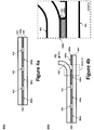
- Figure 1a illustrates a lengthwise cross-sectional view of a multi-layer composite structure 100 comprising a first composite layer 102 (e.g., a substrate, such as a composite fiber layer) bonded to a second composite layer 104 by a bonding agent 106 (e.g., an adhesive, resin, epoxy).
- the bonding agent 106 is arranged into strip-shaped bonds 106a, 106b, 106c, 106n (or beads) that are separated from one another by zones 112 free of a bonding agent 106. Examples of such zones 112 include gaps, voids, regions, etc.
- an adjacent bond e.g., bond 106b
- an adjacent bond is isolated from such dis-bonding via one or more zones 112 such that the adjacent bond remains intact/structurally sound.
- isolating a first bond 106a from a second bond 106b (e.g., an adjacent bond, as illustrated) via one or more zones 112 mitigates the risk dis-bonding at a first bond 106a from propagating to the adjacent bond, in this case the second bond 106; thereby maintaining the integrity of the adjacent bond.
- a bonding agent 106 may be applied to a surface of one or both of the first and second layers 102, 104 to form bonds.
- the bonding agent 106 may be applied to form bonds of different sizes and/or dimensions at different locations.
- the bonding agent 106 may be applied to form a first bond 106a, a second bond 106b, a third bond 106c, .... an nth bond 106n, which may be strip-shaped.
- the first and second layers 102, 104 can then be forced together ( e.g., using weight/pressure) and bonded with the bonding agent 106 positioned therebetween.
- the zones 112 may be air-filled and or filled with a non-adhesive material or vacuumed. This may be done to remove tolerance between the layers and/or prevent unintended debris, moisture, etc., from migrating into the zones 112.
- the zones 112 may be used to house conductors (e.g., electrical conductors to convey electrical power) or to pass fluid (e.g., air/gas).
- zone 112 may be occupied by a bonding agent distinct (e.g., a different type of bonding agent) from bonding agent 116.
- the composite layers 102, 104 may be, for example, a dry composite material, carbon pre-impregnated resin systems ("pre-preg", i.e., composite fibers having uncured matrix material already present), or any other suitable composite material ply. Therefore, in at least one example, the composite layers 102, 104 may be composite fiber layers. While two structural layers 102, 104 are illustrated, one of skill in the art would appreciate that additional layers may be employed as desired for a particular application. Thus, the use of two layers 102, 104 is merely illustrative and the present disclosure should not be construed as limited to a multi-layer composite structure having only two layers.
- the multi-layer composite structure 100 may be co-cured (e.g., the layers create the composite structure as the layers are built up and cured together), and/or co-bonded (e.g., additional layers are bonded to a pre-fabricated structure, e.g., with a resin or other adhesive) with another composite structure (e.g., an existing or pre-manufactured composite piece of an aircraft, for example).
- co-cured e.g., the layers create the composite structure as the layers are built up and cured together
- co-bonded e.g., additional layers are bonded to a pre-fabricated structure, e.g., with a resin or other adhesive
- another composite structure e.g., an existing or pre-manufactured composite piece of an aircraft, for example.
- Figure 1b illustrates a view of the first composite layer 102 prior to bonding to the second composite layer 104 by bonding agent 106.
- the bonding agent 106 has been applied in a strip-shaped pattern of bonds 106a, 106b, 106c, 106n that defines discrete zones 112 where the bonding agent 106 is absent/omitted.
- the bonding agent 106 can be applied in strips spanning the length of layer 104, but can be applied in any suitable pattern that provides sufficient bonding area between layers 102, 104, while maintaining a desired number of zones 112. Further, although illustrated as applied to layer 104, bonding agent 106 can be applied to layer 102 in addition to or as alternative to layer 104.
- zones 112 can vary, dependent on a variety of factors that include, without limitation, type of material of the layers 102, 104, type of bonding agent 106, surface treatments, manufacturing process, desired distance between layers 102, 104, weight, overall required strength of the multi-layer composite structure, etc.
- the width of each zone 112 is 20 to 25 percent the width of the strip of bonding agent 106 ( e.g., a zone to agent ratio of 1:4 - 1:5, although other ratios are contemplated, including those between 1:1 and 1:10).
- each zone 112 may have a width in the range of 0.5 inches to 2 inches (1.3 cm to 5 cm) whereas the width of the bonding agent 106 may be between 2 inches to 10 inches (5 cm to 25 cm). In examples, each zone 112 may have a width in the range of 0.75 inches to 1.25 inches (1.9 cm to 3.2 cm), and the width of the bonding agent 106 may be between 4 inches to 6 inches (10 cm to 15 cm). Therefore, larger and smaller relative dimensions are considered while maintaining the spirit of the disclosure.
- the disclosed bonding patterns have increased stress-bearing capacity of a multi-layer composite structure compared to conventional composites (i.e., complete adhesive coverage).
- the increased stress-bearing capacity of multi-layer composite structure is attributable to the relationships among the respective bond elements, as well as the shape and/or orientation thereof.
- Figure 2a illustrates a lengthwise cross-sectional view of a conventional multi-layer structure 200a comprising a first layer 202a bonded to a second layer 204a by a sheet/layer of bonding agent 206a (e.g., an adhesive bond) along the entire length between the two layers 202a, 204a.
- bonding agent 206a e.g., an adhesive bond
- multi-layer structures typically result in a structure that is stronger than the sum of the individual layers, a failure in the bond can weaken or undo the multi-layer structural integrity.
- dis-bonding and delamination are a common failure of layered materials, such as multi-layer structure 200a.
- Dis-bonding at adhesively bonded interfaces can be caused by a variety of defects.
- increased porosity at a bond can weaken the interfacial integrity between the bonding agent and a composite layer, which can be caused by gases within the bonding agent or adhesive.
- Voids within the bonding agent at a bond may be caused by air entrapment during application of the adhesive, or by insufficient amounts of adhesive being applied to the bonded surfaces.
- Improper or incorrect curing of the adhesive may occur at various locations during application as a result of contaminants or poor mixing of the adhesive's constituent parts. Further, these or other causes can result in cracks in the adhesive, following curing and thermal shrinkage during manufacture, creating brittle or weak bonds. Coupled with the stress on the bonded layers due to the constant and varied forces experienced during flight, a weak bond could fail ( e.g., dis-bond).
- Damage to the structure 200a can occur as a result of repeated exposure to stress or impact, causing layers 202a, 204a to separate with significant loss of mechanical toughness.
- Dis-bonding in adhesive bonds between layers can take on a variety of forms. Example failures in bonding, or dis-bonds, are illustrated in connection with Figures 2 through 3 .
- a multi-layer structure 200b may comprise a first layer 202b, a second layer 202b, and bonding agent 206b.
- dis-bonding has occurred at an interfacial region 208b between the first layer 202b and the bonding agent 206b.
- the first layer 202b has shifted in the direction 210 as a result of the dis-bonding. This is possible as, once an area of the bond is damaged (e.g. discontinuities), the effect may propagate along the interfacial region 208b between the bonding agent 206b and the first layer 202b.
- an initial break/separation at interfacial region 208b may allow the dis-bond to continue along the entire length of the interface.
- Figure 2c shows another type of dis-bonding, where interfacial region 208c has delaminated from first layer 202c to cause a raised portion 216.
- a void 212 has been created as the first layer 202c expands in the direction 214 away from the interfacial region 208c.
- the void 212 could propagate along the length of the bonding agent and outwardly towards the edges.
- Figure 3a illustrates another length wise cross-sectional view of an example multi-layer structure 300a comprising a first layer 302 bonded to a second layer 304 by a bonding agent 306, which was formed as a continuous sheet.
- a defect has occurred at the interfacial region 308 between the first layer 302 and the bonding agent 306.
- dis-bonding tends to propagate along the interface 308, as shown in Figure 3b .
- the first layer 302 is shown separating from the bonding agent 306 as the dis-bonding propagates in direction 310b.
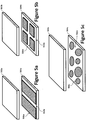
- FIGs 4a and 4b illustrate an example of improved multi-layer composite structures 400a, 400b, which is similar to the multi-layer composite structures 100 described with reference to Figure 1a .
- the multi-layer composite structure 400a includes a first composite layer 402 bonded to a second composite layer 404 by a bonding agent 406 that is arranged into a predetermined bonding pattern.
- the bonding agent 406 is arranged into strip-shaped bonds that are separated from one another by zones 412.
- the bonding agent 406 may be applied to form a first bond 406a, a second bond 406b, a third bond 406c, .... an nth bond 406n; each is illustrated as separated by a zone 412.
- a defect at a first interfacial region 408a of the first bond 406a can cause dis-bonding between the first composite layer 402 and bonding agent 406.
- the second bond 406b at a second interfacial region 408b remains intact.
- the interfacial regions are represented via the dotted line between the composite layers 402, 404 and the bond 406b formed from bonding agent 406.
- the increased strength at the interfacial region can be attributed at least in part to the fillet 414 formed along the length of the edges of the upper and lower interfacial regions between the bond 406b and the composite layers 402, 404.
- the fillet 414 is demonstrated, in Detail A of Figure 4b , as the bonding agent forming an overlay of contacts between the bonding agent 406 and the layers 402, 404 (i.e., interfacial regions). As illustrated in this example, the fillet 414 may form a concave profile about the edges of the bond 406b when viewed in cross-sectional view. Thus, the separation of bonding agents 406 by zones 412 arrests the propagation of defects that can cause dis-bonding of a multi-layer composite structure.
- the bonding agent may be arranged to form bonds of a variety bonding patterns (e.g., strip-shaped bonds 506a, square-shaped bonds 506b, round-shaped bonds 506c, combinations thereof, etc.) to unite sheets of the layered material along the entirety of the length, or along a portion of the length or width of each layer.
- the bonding agent can also be used to bond intermittent portions of layers in a particular configuration, such as defined in terms of length and/or width.
- the bonding agent can further be used to bond portions of various layers according to more than one configuration.
- the bonding agent can yet further be used to bond layers along a defined length of the material.
- the bonding agent can be applied in a variety of different functional bonding patterns.
- the edges of each bonding element of the bond pattern are defined generally by the geometry of the individual layers and/or the desired shape of a completed multi-layer composite structure.
- bonding agent 506a has been applied in a pattern that creates discrete zones 512a where the bonding agent 506a is omitted. As shown, the bonding agent 506a is applied in strips spanning the length of layer 504a, but can be applied in any suitable pattern that provides sufficient bonding area between layers 502a and 504a, while maintaining zones 512a.
- the bonding pattern By designing the bonding pattern so that the adjacent (next closest) bond is separated by a gap defined by the bonding pattern, substantial portions of stress experienced by the multi-layer composite structure are mitigated. Thus, the amount of stress dissipated and/or absorbed at each bonding element is improved.
- Such spacing of the bonding elements from each other provides for distribution of stresses across each layer to a plurality of bonding elements, thereby enhancing distribution of the stress over a relatively larger number of bond elements, as well as over a relatively larger area of the material being bonded, while maintaining the dis-bonding preventive structure disclosed herein.
- Figure 6 illustrates a method 600 of forming a multi-layer composite structure, such as the multi-layer composite structures disclosed with respect to Figures 4a through 5c .
- a surface of a first composite fiber layer (e.g., a first substrate) may be prepared for bonding.
- the preparation may include etching, sanding, or otherwise mechanically modifying a property of the surface, such as with sodium ammonia or sodium naphthalene, so as to facilitate adhesion of the layers using bonding agents, adhesives, commercial-grade epoxies, etc.
- a surface of a second composite fiber layer may be prepared for bonding in a manner similar to that of the first composite fiber layer.
- a bonding agent may be prepared in accordance with the manufacturer's recommendation for the desired bonding agent.
- a hardener Part B
- Part A the resin
- Part A the resin
- Part A the resin
- Part A the resin and hardener
- a bonding agent may be applied as a first bond to one or both surfaces.
- a bonding agent is applied as a second bond to one or both surfaces, the second bond being arranged relative to the first bond such that a gap separates the two bonds.
- the two bonds are isolated from one another by a void, such that discontinuities (e.g., dis-bonding) that may exist in either bond will be prevented from propagating to the other bond.
- the bonding agent is applied in a predefined amount and arrangement (e.g., small, lengthwise beads), such that, upon compression between the first and second layers, a gap remains between the adjacent bonds.
- the first composite layer and the second composite layer may be bonded together by contacting the first surface and the second surface.
- the two layers are adhered together, and the bonding agent is allowed to cure for a duration of time needed to bond to a strength suitable to satisfy aircraft standards.
- forming the multi-layer composite structure by method 600 may include composite layers that are laid up (co-bonded or co-cured; e.g., impregnated during manufacturing of the composite structure, co-cured) with another composite material or structure and, once cured, becomes part of the composite structure (e.g., a spar, wing, etc.).
- the material e.g., a liquid epoxy
- the material used to fabricate the composite structure may also be used as a bonding agent to bond the one or more layers.
- epoxy and Bis-Maleimide (BM) pre-impregnated resin systems are two suitable composite matrices for aircraft structures.
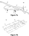
- FIGS. 7a and 7b illustrate an example fixed-wing aerial vehicle 700.
- the fixed wing aircraft 700 may comprise an airframe 702 (e.g., a fuselage or chassis), landing gear 704, and one or more thrust generators 706 to provide lift or thrust (e.g., a turbine, a motor or engine operatively coupled with a propeller, etc.), and one or more fixed wings 708.
- the one or more fixed wings 708 may be coupled to the airframe 702.
- the fixed wing aircraft 700 may instead be configured as a blended-wing or flying-wing configuration, for example.
- Figure 7b depicts a section of an example aircraft wing 708.
- the aircraft wing 708 generally comprises spars 710 (e.g., a main spar), ribs 712, and wing panels 714.
- spars 710 e.g., a main spar
- ribs 712 e.g., a main spar
- wing panels 714 e.g., a multi-layer bonded composite structure that employs a bonding agent in an intermittent bonding pattern.
Landscapes
- Engineering & Computer Science (AREA)
- Manufacturing & Machinery (AREA)
- Transportation (AREA)
- Aviation & Aerospace Engineering (AREA)
- Laminated Bodies (AREA)
Applications Claiming Priority (1)
| Application Number | Priority Date | Filing Date | Title |
|---|---|---|---|
| US16/228,236 US20200198295A1 (en) | 2018-12-20 | 2018-12-20 | Composite Structures With Discontinuous Bond Lines |
Publications (2)
| Publication Number | Publication Date |
|---|---|
| EP3674077A1 true EP3674077A1 (de) | 2020-07-01 |
| EP3674077B1 EP3674077B1 (de) | 2022-07-13 |
Family
ID=68531425
Family Applications (1)
| Application Number | Title | Priority Date | Filing Date |
|---|---|---|---|
| EP19208276.6A Active EP3674077B1 (de) | 2018-12-20 | 2019-11-11 | Verbundstrukturen mit diskontinuierlichen verbindungslinien |
Country Status (3)
| Country | Link |
|---|---|
| US (1) | US20200198295A1 (de) |
| EP (1) | EP3674077B1 (de) |
| CN (1) | CN111347729B (de) |
Families Citing this family (2)
| Publication number | Priority date | Publication date | Assignee | Title |
|---|---|---|---|---|
| EP4138525A1 (de) * | 2021-08-17 | 2023-02-22 | Airbus S.A.S. | Verfahren zur herstellung eines paneels mit integrierter elektronik |
| CN114742192A (zh) * | 2022-03-03 | 2022-07-12 | 珠海全球时代科技有限公司 | 不易折断的可降解环保卡片及其制备方法 |
Citations (2)
| Publication number | Priority date | Publication date | Assignee | Title |
|---|---|---|---|---|
| EP1138475A2 (de) * | 2000-03-31 | 2001-10-04 | Uni-Charm Corporation | Verbundwerkstoff und Verfahren zu seiner Herstellung |
| US20120244769A1 (en) * | 2011-03-25 | 2012-09-27 | Honeywell International Inc. | Methods to improve the process-ability of uni-directional composites |
Family Cites Families (3)
| Publication number | Priority date | Publication date | Assignee | Title |
|---|---|---|---|---|
| US4111081A (en) * | 1976-01-02 | 1978-09-05 | The Boeing Company | Low non-linearity factor sound attenuating laminate |
| CA2557572A1 (en) * | 2004-03-02 | 2005-09-09 | Toray Industries, Inc. | Epoxy resin composition for fiber-reinforced composite material, prepreg and fiber-reinforced composite material |
| US8524356B1 (en) * | 2009-03-09 | 2013-09-03 | The Boeing Company | Bonded patch having multiple zones of fracture toughness |
-
2018
- 2018-12-20 US US16/228,236 patent/US20200198295A1/en not_active Abandoned
-
2019
- 2019-11-11 EP EP19208276.6A patent/EP3674077B1/de active Active
- 2019-12-19 CN CN201911317973.7A patent/CN111347729B/zh active Active
Patent Citations (2)
| Publication number | Priority date | Publication date | Assignee | Title |
|---|---|---|---|---|
| EP1138475A2 (de) * | 2000-03-31 | 2001-10-04 | Uni-Charm Corporation | Verbundwerkstoff und Verfahren zu seiner Herstellung |
| US20120244769A1 (en) * | 2011-03-25 | 2012-09-27 | Honeywell International Inc. | Methods to improve the process-ability of uni-directional composites |
Also Published As
| Publication number | Publication date |
|---|---|
| CN111347729A (zh) | 2020-06-30 |
| CN111347729B (zh) | 2024-02-09 |
| EP3674077B1 (de) | 2022-07-13 |
| US20200198295A1 (en) | 2020-06-25 |
Similar Documents
| Publication | Publication Date | Title |
|---|---|---|
| CN103507941B (zh) | 复合材料帽形加筋件、复合材料帽形加筋压力腹板及其制造方法 | |
| EP2406062B1 (de) | Vorhersagbare geklebte nachbesserung von verbundstrukturen unter verwendung von massgeschneiderten flicken | |
| CA2754624C (en) | Tapered patch for predictable bonded rework of composite structures | |
| CN106184709B (zh) | 具有减小面积的半径填料的复合结构及其形成方法 | |
| JP6360672B2 (ja) | 複合材径フィラーとその形成方法 | |
| EP2406061B1 (de) | Vorhersagbare geklebte nachbesserung von verbundstrukturen | |
| EP2609008B1 (de) | Verbundflugzeugverbindung | |
| US8524356B1 (en) | Bonded patch having multiple zones of fracture toughness | |
| US9393768B2 (en) | Discretely tailored multi-zone bondline for fail-safe structural repair | |
| JP6587635B2 (ja) | テーパ状の接着設計を有する構造的な接合パッチ | |
| EP2345532B1 (de) | Längliche Konfiguration für Haftpatch | |
| EP3674077B1 (de) | Verbundstrukturen mit diskontinuierlichen verbindungslinien | |
| JP7356821B2 (ja) | 垂直補強材の共硬化方法 | |
| CN121133982A (zh) | 具有钛端部的复合面板 | |
| CN121139561A (zh) | 金属-复合材料接头 | |
| HK1165758B (en) | Tapered patch for predictable bonded rework of composite structures |
Legal Events
| Date | Code | Title | Description |
|---|---|---|---|
| PUAI | Public reference made under article 153(3) epc to a published international application that has entered the european phase |
Free format text: ORIGINAL CODE: 0009012 |
|
| STAA | Information on the status of an ep patent application or granted ep patent |
Free format text: STATUS: THE APPLICATION HAS BEEN PUBLISHED |
|
| AK | Designated contracting states |
Kind code of ref document: A1 Designated state(s): AL AT BE BG CH CY CZ DE DK EE ES FI FR GB GR HR HU IE IS IT LI LT LU LV MC MK MT NL NO PL PT RO RS SE SI SK SM TR |
|
| AX | Request for extension of the european patent |
Extension state: BA ME |
|
| STAA | Information on the status of an ep patent application or granted ep patent |
Free format text: STATUS: REQUEST FOR EXAMINATION WAS MADE |
|
| 17P | Request for examination filed |
Effective date: 20201223 |
|
| RBV | Designated contracting states (corrected) |
Designated state(s): AL AT BE BG CH CY CZ DE DK EE ES FI FR GB GR HR HU IE IS IT LI LT LU LV MC MK MT NL NO PL PT RO RS SE SI SK SM TR |
|
| GRAP | Despatch of communication of intention to grant a patent |
Free format text: ORIGINAL CODE: EPIDOSNIGR1 |
|
| STAA | Information on the status of an ep patent application or granted ep patent |
Free format text: STATUS: GRANT OF PATENT IS INTENDED |
|
| INTG | Intention to grant announced |
Effective date: 20220210 |
|
| GRAS | Grant fee paid |
Free format text: ORIGINAL CODE: EPIDOSNIGR3 |
|
| GRAA | (expected) grant |
Free format text: ORIGINAL CODE: 0009210 |
|
| STAA | Information on the status of an ep patent application or granted ep patent |
Free format text: STATUS: THE PATENT HAS BEEN GRANTED |
|
| AK | Designated contracting states |
Kind code of ref document: B1 Designated state(s): AL AT BE BG CH CY CZ DE DK EE ES FI FR GB GR HR HU IE IS IT LI LT LU LV MC MK MT NL NO PL PT RO RS SE SI SK SM TR |
|
| REG | Reference to a national code |
Ref country code: CH Ref legal event code: EP |
|
| REG | Reference to a national code |
Ref country code: DE Ref legal event code: R096 Ref document number: 602019016932 Country of ref document: DE |
|
| REG | Reference to a national code |
Ref country code: AT Ref legal event code: REF Ref document number: 1504067 Country of ref document: AT Kind code of ref document: T Effective date: 20220815 |
|
| REG | Reference to a national code |
Ref country code: IE Ref legal event code: FG4D |
|
| REG | Reference to a national code |
Ref country code: LT Ref legal event code: MG9D |
|
| REG | Reference to a national code |
Ref country code: NL Ref legal event code: MP Effective date: 20220713 |
|
| PG25 | Lapsed in a contracting state [announced via postgrant information from national office to epo] |
Ref country code: SE Free format text: LAPSE BECAUSE OF FAILURE TO SUBMIT A TRANSLATION OF THE DESCRIPTION OR TO PAY THE FEE WITHIN THE PRESCRIBED TIME-LIMIT Effective date: 20220713 Ref country code: RS Free format text: LAPSE BECAUSE OF FAILURE TO SUBMIT A TRANSLATION OF THE DESCRIPTION OR TO PAY THE FEE WITHIN THE PRESCRIBED TIME-LIMIT Effective date: 20220713 Ref country code: PT Free format text: LAPSE BECAUSE OF FAILURE TO SUBMIT A TRANSLATION OF THE DESCRIPTION OR TO PAY THE FEE WITHIN THE PRESCRIBED TIME-LIMIT Effective date: 20221114 Ref country code: NO Free format text: LAPSE BECAUSE OF FAILURE TO SUBMIT A TRANSLATION OF THE DESCRIPTION OR TO PAY THE FEE WITHIN THE PRESCRIBED TIME-LIMIT Effective date: 20221013 Ref country code: NL Free format text: LAPSE BECAUSE OF FAILURE TO SUBMIT A TRANSLATION OF THE DESCRIPTION OR TO PAY THE FEE WITHIN THE PRESCRIBED TIME-LIMIT Effective date: 20220713 Ref country code: LV Free format text: LAPSE BECAUSE OF FAILURE TO SUBMIT A TRANSLATION OF THE DESCRIPTION OR TO PAY THE FEE WITHIN THE PRESCRIBED TIME-LIMIT Effective date: 20220713 Ref country code: LT Free format text: LAPSE BECAUSE OF FAILURE TO SUBMIT A TRANSLATION OF THE DESCRIPTION OR TO PAY THE FEE WITHIN THE PRESCRIBED TIME-LIMIT Effective date: 20220713 Ref country code: FI Free format text: LAPSE BECAUSE OF FAILURE TO SUBMIT A TRANSLATION OF THE DESCRIPTION OR TO PAY THE FEE WITHIN THE PRESCRIBED TIME-LIMIT Effective date: 20220713 Ref country code: ES Free format text: LAPSE BECAUSE OF FAILURE TO SUBMIT A TRANSLATION OF THE DESCRIPTION OR TO PAY THE FEE WITHIN THE PRESCRIBED TIME-LIMIT Effective date: 20220713 |
|
| REG | Reference to a national code |
Ref country code: AT Ref legal event code: MK05 Ref document number: 1504067 Country of ref document: AT Kind code of ref document: T Effective date: 20220713 |
|
| PG25 | Lapsed in a contracting state [announced via postgrant information from national office to epo] |
Ref country code: PL Free format text: LAPSE BECAUSE OF FAILURE TO SUBMIT A TRANSLATION OF THE DESCRIPTION OR TO PAY THE FEE WITHIN THE PRESCRIBED TIME-LIMIT Effective date: 20220713 Ref country code: IS Free format text: LAPSE BECAUSE OF FAILURE TO SUBMIT A TRANSLATION OF THE DESCRIPTION OR TO PAY THE FEE WITHIN THE PRESCRIBED TIME-LIMIT Effective date: 20221113 Ref country code: HR Free format text: LAPSE BECAUSE OF FAILURE TO SUBMIT A TRANSLATION OF THE DESCRIPTION OR TO PAY THE FEE WITHIN THE PRESCRIBED TIME-LIMIT Effective date: 20220713 Ref country code: GR Free format text: LAPSE BECAUSE OF FAILURE TO SUBMIT A TRANSLATION OF THE DESCRIPTION OR TO PAY THE FEE WITHIN THE PRESCRIBED TIME-LIMIT Effective date: 20221014 |
|
| REG | Reference to a national code |
Ref country code: DE Ref legal event code: R097 Ref document number: 602019016932 Country of ref document: DE |
|
| PG25 | Lapsed in a contracting state [announced via postgrant information from national office to epo] |
Ref country code: SM Free format text: LAPSE BECAUSE OF FAILURE TO SUBMIT A TRANSLATION OF THE DESCRIPTION OR TO PAY THE FEE WITHIN THE PRESCRIBED TIME-LIMIT Effective date: 20220713 Ref country code: RO Free format text: LAPSE BECAUSE OF FAILURE TO SUBMIT A TRANSLATION OF THE DESCRIPTION OR TO PAY THE FEE WITHIN THE PRESCRIBED TIME-LIMIT Effective date: 20220713 Ref country code: DK Free format text: LAPSE BECAUSE OF FAILURE TO SUBMIT A TRANSLATION OF THE DESCRIPTION OR TO PAY THE FEE WITHIN THE PRESCRIBED TIME-LIMIT Effective date: 20220713 Ref country code: CZ Free format text: LAPSE BECAUSE OF FAILURE TO SUBMIT A TRANSLATION OF THE DESCRIPTION OR TO PAY THE FEE WITHIN THE PRESCRIBED TIME-LIMIT Effective date: 20220713 Ref country code: AT Free format text: LAPSE BECAUSE OF FAILURE TO SUBMIT A TRANSLATION OF THE DESCRIPTION OR TO PAY THE FEE WITHIN THE PRESCRIBED TIME-LIMIT Effective date: 20220713 |
|
| PLBE | No opposition filed within time limit |
Free format text: ORIGINAL CODE: 0009261 |
|
| STAA | Information on the status of an ep patent application or granted ep patent |
Free format text: STATUS: NO OPPOSITION FILED WITHIN TIME LIMIT |
|
| PG25 | Lapsed in a contracting state [announced via postgrant information from national office to epo] |
Ref country code: SK Free format text: LAPSE BECAUSE OF FAILURE TO SUBMIT A TRANSLATION OF THE DESCRIPTION OR TO PAY THE FEE WITHIN THE PRESCRIBED TIME-LIMIT Effective date: 20220713 Ref country code: EE Free format text: LAPSE BECAUSE OF FAILURE TO SUBMIT A TRANSLATION OF THE DESCRIPTION OR TO PAY THE FEE WITHIN THE PRESCRIBED TIME-LIMIT Effective date: 20220713 |
|
| 26N | No opposition filed |
Effective date: 20230414 |
|
| P01 | Opt-out of the competence of the unified patent court (upc) registered |
Effective date: 20230516 |
|
| PG25 | Lapsed in a contracting state [announced via postgrant information from national office to epo] |
Ref country code: MC Free format text: LAPSE BECAUSE OF FAILURE TO SUBMIT A TRANSLATION OF THE DESCRIPTION OR TO PAY THE FEE WITHIN THE PRESCRIBED TIME-LIMIT Effective date: 20220713 Ref country code: AL Free format text: LAPSE BECAUSE OF FAILURE TO SUBMIT A TRANSLATION OF THE DESCRIPTION OR TO PAY THE FEE WITHIN THE PRESCRIBED TIME-LIMIT Effective date: 20220713 |
|
| REG | Reference to a national code |
Ref country code: CH Ref legal event code: PL |
|
| REG | Reference to a national code |
Ref country code: BE Ref legal event code: MM Effective date: 20221130 |
|
| PG25 | Lapsed in a contracting state [announced via postgrant information from national office to epo] |
Ref country code: LI Free format text: LAPSE BECAUSE OF NON-PAYMENT OF DUE FEES Effective date: 20221130 Ref country code: CH Free format text: LAPSE BECAUSE OF NON-PAYMENT OF DUE FEES Effective date: 20221130 |
|
| PG25 | Lapsed in a contracting state [announced via postgrant information from national office to epo] |
Ref country code: SI Free format text: LAPSE BECAUSE OF FAILURE TO SUBMIT A TRANSLATION OF THE DESCRIPTION OR TO PAY THE FEE WITHIN THE PRESCRIBED TIME-LIMIT Effective date: 20220713 Ref country code: LU Free format text: LAPSE BECAUSE OF NON-PAYMENT OF DUE FEES Effective date: 20221111 |
|
| PG25 | Lapsed in a contracting state [announced via postgrant information from national office to epo] |
Ref country code: IE Free format text: LAPSE BECAUSE OF NON-PAYMENT OF DUE FEES Effective date: 20221111 |
|
| PG25 | Lapsed in a contracting state [announced via postgrant information from national office to epo] |
Ref country code: BE Free format text: LAPSE BECAUSE OF NON-PAYMENT OF DUE FEES Effective date: 20221130 |
|
| PG25 | Lapsed in a contracting state [announced via postgrant information from national office to epo] |
Ref country code: IT Free format text: LAPSE BECAUSE OF FAILURE TO SUBMIT A TRANSLATION OF THE DESCRIPTION OR TO PAY THE FEE WITHIN THE PRESCRIBED TIME-LIMIT Effective date: 20220713 |
|
| PG25 | Lapsed in a contracting state [announced via postgrant information from national office to epo] |
Ref country code: HU Free format text: LAPSE BECAUSE OF FAILURE TO SUBMIT A TRANSLATION OF THE DESCRIPTION OR TO PAY THE FEE WITHIN THE PRESCRIBED TIME-LIMIT; INVALID AB INITIO Effective date: 20191111 |
|
| PG25 | Lapsed in a contracting state [announced via postgrant information from national office to epo] |
Ref country code: CY Free format text: LAPSE BECAUSE OF FAILURE TO SUBMIT A TRANSLATION OF THE DESCRIPTION OR TO PAY THE FEE WITHIN THE PRESCRIBED TIME-LIMIT Effective date: 20220713 |
|
| PG25 | Lapsed in a contracting state [announced via postgrant information from national office to epo] |
Ref country code: MK Free format text: LAPSE BECAUSE OF FAILURE TO SUBMIT A TRANSLATION OF THE DESCRIPTION OR TO PAY THE FEE WITHIN THE PRESCRIBED TIME-LIMIT Effective date: 20220713 |
|
| PG25 | Lapsed in a contracting state [announced via postgrant information from national office to epo] |
Ref country code: BG Free format text: LAPSE BECAUSE OF FAILURE TO SUBMIT A TRANSLATION OF THE DESCRIPTION OR TO PAY THE FEE WITHIN THE PRESCRIBED TIME-LIMIT Effective date: 20220713 |
|
| PG25 | Lapsed in a contracting state [announced via postgrant information from national office to epo] |
Ref country code: MT Free format text: LAPSE BECAUSE OF FAILURE TO SUBMIT A TRANSLATION OF THE DESCRIPTION OR TO PAY THE FEE WITHIN THE PRESCRIBED TIME-LIMIT Effective date: 20220713 |
|
| PG25 | Lapsed in a contracting state [announced via postgrant information from national office to epo] |
Ref country code: TR Free format text: LAPSE BECAUSE OF FAILURE TO SUBMIT A TRANSLATION OF THE DESCRIPTION OR TO PAY THE FEE WITHIN THE PRESCRIBED TIME-LIMIT Effective date: 20220713 |
|
| PGFP | Annual fee paid to national office [announced via postgrant information from national office to epo] |
Ref country code: DE Payment date: 20251128 Year of fee payment: 7 |
|
| PGFP | Annual fee paid to national office [announced via postgrant information from national office to epo] |
Ref country code: GB Payment date: 20251127 Year of fee payment: 7 |
|
| PGFP | Annual fee paid to national office [announced via postgrant information from national office to epo] |
Ref country code: FR Payment date: 20251125 Year of fee payment: 7 |