EP3673880A1 - Vorrichtung zur herstellung von absorbierenden hygieneartikeln mit einer perforationsvorrichtung einer bahn und verfahren - Google Patents
Vorrichtung zur herstellung von absorbierenden hygieneartikeln mit einer perforationsvorrichtung einer bahn und verfahren Download PDFInfo
- Publication number
- EP3673880A1 EP3673880A1 EP19209501.6A EP19209501A EP3673880A1 EP 3673880 A1 EP3673880 A1 EP 3673880A1 EP 19209501 A EP19209501 A EP 19209501A EP 3673880 A1 EP3673880 A1 EP 3673880A1
- Authority
- EP
- European Patent Office
- Prior art keywords
- web
- mantle
- protruding
- roller
- protruding pattern
- Prior art date
- Legal status (The legal status is an assumption and is not a legal conclusion. Google has not performed a legal analysis and makes no representation as to the accuracy of the status listed.)
- Granted
Links
Images

Classifications
-
- A—HUMAN NECESSITIES
- A61—MEDICAL OR VETERINARY SCIENCE; HYGIENE
- A61F—FILTERS IMPLANTABLE INTO BLOOD VESSELS; PROSTHESES; DEVICES PROVIDING PATENCY TO, OR PREVENTING COLLAPSING OF, TUBULAR STRUCTURES OF THE BODY, e.g. STENTS; ORTHOPAEDIC, NURSING OR CONTRACEPTIVE DEVICES; FOMENTATION; TREATMENT OR PROTECTION OF EYES OR EARS; BANDAGES, DRESSINGS OR ABSORBENT PADS; FIRST-AID KITS
- A61F13/00—Bandages or dressings; Absorbent pads
- A61F13/15—Absorbent pads, e.g. sanitary towels, swabs or tampons for external or internal application to the body; Supporting or fastening means therefor; Tampon applicators
- A61F13/15577—Apparatus or processes for manufacturing
- A61F13/15707—Mechanical treatment, e.g. notching, twisting, compressing, shaping
-
- A—HUMAN NECESSITIES
- A61—MEDICAL OR VETERINARY SCIENCE; HYGIENE
- A61F—FILTERS IMPLANTABLE INTO BLOOD VESSELS; PROSTHESES; DEVICES PROVIDING PATENCY TO, OR PREVENTING COLLAPSING OF, TUBULAR STRUCTURES OF THE BODY, e.g. STENTS; ORTHOPAEDIC, NURSING OR CONTRACEPTIVE DEVICES; FOMENTATION; TREATMENT OR PROTECTION OF EYES OR EARS; BANDAGES, DRESSINGS OR ABSORBENT PADS; FIRST-AID KITS
- A61F13/00—Bandages or dressings; Absorbent pads
- A61F13/15—Absorbent pads, e.g. sanitary towels, swabs or tampons for external or internal application to the body; Supporting or fastening means therefor; Tampon applicators
- A61F13/15577—Apparatus or processes for manufacturing
- A61F13/15707—Mechanical treatment, e.g. notching, twisting, compressing, shaping
- A61F13/15731—Treating webs, e.g. for giving them a fibrelike appearance, e.g. by embossing
-
- A—HUMAN NECESSITIES
- A61—MEDICAL OR VETERINARY SCIENCE; HYGIENE
- A61F—FILTERS IMPLANTABLE INTO BLOOD VESSELS; PROSTHESES; DEVICES PROVIDING PATENCY TO, OR PREVENTING COLLAPSING OF, TUBULAR STRUCTURES OF THE BODY, e.g. STENTS; ORTHOPAEDIC, NURSING OR CONTRACEPTIVE DEVICES; FOMENTATION; TREATMENT OR PROTECTION OF EYES OR EARS; BANDAGES, DRESSINGS OR ABSORBENT PADS; FIRST-AID KITS
- A61F13/00—Bandages or dressings; Absorbent pads
- A61F13/15—Absorbent pads, e.g. sanitary towels, swabs or tampons for external or internal application to the body; Supporting or fastening means therefor; Tampon applicators
- A61F13/51—Absorbent pads, e.g. sanitary towels, swabs or tampons for external or internal application to the body; Supporting or fastening means therefor; Tampon applicators characterised by the outer layers of the pads
- A61F13/511—Topsheet, i.e. the permeable cover or layer facing the skin
- A61F13/512—Topsheet, i.e. the permeable cover or layer facing the skin characterised by its apertures, e.g. perforations
-
- A—HUMAN NECESSITIES
- A61—MEDICAL OR VETERINARY SCIENCE; HYGIENE
- A61F—FILTERS IMPLANTABLE INTO BLOOD VESSELS; PROSTHESES; DEVICES PROVIDING PATENCY TO, OR PREVENTING COLLAPSING OF, TUBULAR STRUCTURES OF THE BODY, e.g. STENTS; ORTHOPAEDIC, NURSING OR CONTRACEPTIVE DEVICES; FOMENTATION; TREATMENT OR PROTECTION OF EYES OR EARS; BANDAGES, DRESSINGS OR ABSORBENT PADS; FIRST-AID KITS
- A61F13/00—Bandages or dressings; Absorbent pads
- A61F13/15—Absorbent pads, e.g. sanitary towels, swabs or tampons for external or internal application to the body; Supporting or fastening means therefor; Tampon applicators
- A61F13/51—Absorbent pads, e.g. sanitary towels, swabs or tampons for external or internal application to the body; Supporting or fastening means therefor; Tampon applicators characterised by the outer layers of the pads
- A61F13/511—Topsheet, i.e. the permeable cover or layer facing the skin
- A61F13/513—Topsheet, i.e. the permeable cover or layer facing the skin characterised by its function or properties, e.g. stretchability, breathability, rewet, visual effect; having areas of different permeability
- A61F13/51394—Topsheet, i.e. the permeable cover or layer facing the skin characterised by its function or properties, e.g. stretchability, breathability, rewet, visual effect; having areas of different permeability creating a visual effect, e.g. having a printed or coloured topsheet, printed or coloured sub-layer but being visible from the topsheet, other than embossing for purposes of bonding, wicking, acquisition, leakage-prevention
-
- B—PERFORMING OPERATIONS; TRANSPORTING
- B26—HAND CUTTING TOOLS; CUTTING; SEVERING
- B26F—PERFORATING; PUNCHING; CUTTING-OUT; STAMPING-OUT; SEVERING BY MEANS OTHER THAN CUTTING
- B26F1/00—Perforating; Punching; Cutting-out; Stamping-out; Apparatus therefor
- B26F1/02—Perforating by punching, e.g. with relatively-reciprocating punch and bed
- B26F1/06—Perforating by punching, e.g. with relatively-reciprocating punch and bed with punching tools moving with the work
- B26F1/10—Roller type punches
-
- A—HUMAN NECESSITIES
- A61—MEDICAL OR VETERINARY SCIENCE; HYGIENE
- A61F—FILTERS IMPLANTABLE INTO BLOOD VESSELS; PROSTHESES; DEVICES PROVIDING PATENCY TO, OR PREVENTING COLLAPSING OF, TUBULAR STRUCTURES OF THE BODY, e.g. STENTS; ORTHOPAEDIC, NURSING OR CONTRACEPTIVE DEVICES; FOMENTATION; TREATMENT OR PROTECTION OF EYES OR EARS; BANDAGES, DRESSINGS OR ABSORBENT PADS; FIRST-AID KITS
- A61F13/00—Bandages or dressings; Absorbent pads
- A61F13/15—Absorbent pads, e.g. sanitary towels, swabs or tampons for external or internal application to the body; Supporting or fastening means therefor; Tampon applicators
- A61F13/15577—Apparatus or processes for manufacturing
- A61F2013/15821—Apparatus or processes for manufacturing characterized by the apparatus for manufacturing
- A61F2013/15934—Apparatus or processes for manufacturing characterized by the apparatus for manufacturing for making non-woven
Definitions
- Embodiments of the present invention relate to an apparatus for producing sanitary absorbent articles comprising at least one perforating device of at least one web intended for making sanitary absorbent articles, such as diapers, diaper-pants, incontinence pads, sanitary pads, or other articles intended to absorb bodily fluids.
- Embodiments of the present invention relate to a perforating device usable in an apparatus for producing sanitary absorbent articles having portions provided with one or more perforated patterns in relation to the desired production requirements.
- perforated pattern of a web and/or of a portion of sanitary absorbent article means a spatially delimited zone wherein holes spaced apart are present.
- the present invention also relates to a perforating process implemented in an apparatus for producing sanitary absorbent articles comprising at least one perforating device capable of making perforated patterns on at least one web intended for making sanitary absorbent articles.
- That known solution involves high costs, requires lengthy times for loading in line and for supplying, and necessitates large warehouse spaces and numbers of personnel.
- webs are made having a plurality of continuous holes constituting a single perforated pattern which extends for the whole length of the web.
- Such solutions provide for the use of a calender provided with one or more pairs of rollers on which a plurality of needles, or protruding elements are present, suitable for perforating the web while it passes through the calender itself.
- extension of the web means the extension of the web in the sense of its length, that is to say, along the machine direction if the web is advanced with its longitudinal axis along the machine direction.
- the holes made in the web with the known solutions may have unwanted elliptical shapes and/or lacerated and/or stretched portions, or in the worst cases the web may even remain accidentally caught in the perforating device.
- One aim of the present invention is to supply an apparatus for producing sanitary absorbent articles comprising a perforating device capable of making perforated patterns spaced apart along the extension of the web directly in line and with high production rates.
- a further aim of the present invention is to supply an apparatus for producing sanitary absorbent articles comprising a perforating device capable of making in line perforated patterns in a web which are precise and without imperfections so as to obtain sanitary absorbent articles corresponding to design expectations.
- It is also an aim of the present invention to supply an apparatus for producing sanitary absorbent articles comprising a perforating device capable of guaranteeing high performance and stability, that is to say, such that it does not require frequent interventions by operators.
- possible embodiments of the present invention relate to an apparatus for producing sanitary absorbent articles comprising at least one perforating device of at least one web intended for making sanitary absorbent articles.
- the perforating device comprises a first roller and a second roller respectively provided with a first mantle and a second mantle and between which, in use, the web passes.
- the first roller and the second roller are configured to rotate in opposite directions respectively around a first axis of rotation at a first velocity and around a second axis of rotation, parallel to the first axis of rotation, at a second velocity different from the first velocity.
- the first mantle comprises a first protruding pattern and the second mantle comprises at least a first zone, wherein a second protruding pattern is present, and at least a second zone without protruding patterns.
- the second zone is adjacent to the first zone along a circumference of the second mantle.
- the second protruding pattern is configured, in use, to temporally engage the web with the first protruding pattern without interpenetrating the latter for locally perforating the web.
- the perforating device allows the obtainment of perforated patterns spaced apart along the extension of the web directly in line and rapidly while the web passes through the pair of rollers.
- the web is locally perforated in correspondence with the engagement zones of the protruding patterns with the web.
- the fibres of the web are spaced apart and/or locally removed to form the holes of which the perforated patterns are composed.
- the joint action of the protruding patterns also allows the fibres of the web to be fixed in correspondence with the edge of the holes so that they keep the shape even after the disengagement of the protruding patterns.
- rollers directly in line renders the production apparatuses capable of making sanitary absorbent articles provided with perforated patterns with high production rates, simultaneously guaranteeing high stability in the processes.
- the perforating device allows the web to be perforated intermittently, that is to say, in phase, starting from a web without holes, while it passes through the pair of rollers.
- the perforating device therefore allows the use of different webs and making of the holes when necessary along the advancement path of the web in the apparatus so as to be able to design portions of the apparatus in a unique way for performing processing on non-perforated webs which may even be different from each other.
- the mechanical properties of the non-perforated webs allow simplification of the processing units of the production apparatus and therefore keeping the designs dedicated to perforated webs only in the portions of the apparatus downstream of the perforating device.
- first mantle having a first protruding pattern with a second mantle having portions with a second protruding pattern and zones without protruding patterns guarantees a high stability of the intermittent perforating process since engagement of the protruding patterns with each other is guaranteed.
- the second mantle may comprise a plurality of first zones and a plurality of second zones arranged alternately along a circumference of the second mantle.
- the first protruding pattern may have a protruding profile inclined by an angle of inclination with respect to the first axis of rotation equal to or less than 90°.
- the second protruding pattern may have a protruding profile inclined by an angle of inclination with respect to the second axis of rotation equal to or less than 90°.
- the first protruding pattern and the second protruding pattern may have the same protruding profile inclined so that, in use, the respective inclined protruding profiles of the first protruding pattern and of the second protruding pattern intersect each other in localized zones of the web to locally perforate it.
- the maximum distance between the second axis of rotation and the second zone may be less than the maximum distance between the second axis of rotation and the first zone.
- the perforating device may comprise at least one spacer member coupled with the first roller and/or with the second roller and configured, in use, to keep the first protruding pattern spaced apart from the surface of the second zone of the second mantle by a distance equal to the distance between the surface of the second zone of the second mantle and the outermost end of the second protruding pattern.
- the perimeter of the first zone may be shaped in relation to the perimeter of the perforated pattern to be made on the web.
- the production apparatus may comprise a printing unit placed upstream of the perforating device and configured to print a plurality of graphic patterns spaced apart along the extension of the web.
- the perforating device is configured to make holes in correspondence with the graphic patterns so as to make a plurality of perforated graphic patterns spaced apart along the extension of the web.
- the first roller and/or the second roller are coupled with heating means configured to heat the first roller and/or the second roller for perforating, in use, the web heating it locally.
- the present invention also relates to a process for perforating at least one web intended for making sanitary absorbent articles implemented in an apparatus for producing sanitary absorbent articles comprising at least one perforating device as in any of the embodiments of the present invention.
- the perforating process may provide to:
- the perforating process may provide that the advancing velocity is comprised between the first velocity and the second velocity.
- the perforating process may provide that the advancing velocity is equal to the first velocity or to the second velocity.
- the perforating process may provide that the first protruding pattern and the second protruding pattern have a protruding profile inclined at the same angle of inclination with respect to the corresponding axis of rotation, wherein the process may provide to perforate the web in correspondence with the intersections of the inclined protruding profiles of the first protruding pattern and of the second protruding pattern.
- the perforating process may provide that the second zone does not touch the web while the latter passes between the first roller and the second roller.
- the perforating process may provide to print a plurality of graphic patterns spaced apart on the web before making the perforated patterns.
- the perforating process may provide to make the perforated patterns in correspondence with the graphic patterns.
- the perforating process may provide to make a plurality of embossing on the web after having made the perforated patterns.
- the perforating process may provide that the web is a composite web comprising a first layer of non-woven fabric, a second layer of non-woven fabric and at least one elastic element placed between the first layer and the second layer.
- the perforating process may provide to locally weld the first layer and the second layer together while the elastic element is tensioned.
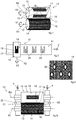
- Embodiments described herein, with reference to the figures, relate to a perforating device 10 of at least one web 11 intended for making sanitary absorbent articles.
- the perforating device 10 is configured to make perforated patterns 20 spaced apart along the extension of the web 11, wherein the perforated patterns 20 are provided with holes spaced apart.
- the web 11 may comprise a plurality of perforated patterns 20 having desired shapes and dimensions in relation to the perforating device 10 and to the operating parameters of the later.
- the perforating device 10 may comprise a first roller 12 and a second roller 13 respectively provided with a first mantle 14 and a second mantle 15 and between which, in use, the web 11 passes.
- the first roller 12 and the second roller 13 may be configured to rotate in opposite directions respectively around a first axis of rotation R1 at a first velocity V1 and around a second axis of rotation R2, parallel to the first axis of rotation R1, at a second velocity V2 different from the first velocity V1.
- the web 11 to be advanced through the two mantles 14 and 15 along a desired direction. Moreover, the different velocity of the two rollers 12 and 13 allows a plurality of localized holes to be made on the web 11.
- the first roller 12 and the second roller 13 may rotate by means of a movement member.
- the movement member may comprise a motor, an actuator and/or another movement system if necessary provided with means for the transmission and/or conversion of the motion.
- the rollers 12 and 13 may rotate in a coordinated way by means of a common movement member suitable for making both rollers rotate in a coordinated way.
- the first mantle 14 may comprise a first protruding pattern 16.
- the first protruding pattern 16 may comprise a plurality of protrusions towards the outside of the first mantle 14.
- the first protruding pattern 16 may comprise a helical profile, that is to say, a continuous protrusion wrapped around the first roller 12 with a desired space between the coils.
- the helical profile may comprise a plurality of protrusions wrapped around the first roller 12 with a desired space between the coils.
- the first mantle 14 may comprise at least one zone without protruding patterns adjacent to the first protruding pattern 16 along a circumference of the first mantle 14.
- the circumference may be defined as the perimeter of a section of the first mantle 14 orthogonal to the longitudinal axis of the first roller 12.
- the latter may be connected to the surface of the first mantle 14.
- the second mantle 15 may comprise at least a first zone 17, wherein a second protruding pattern 18 is present, and at least a second zone 19 without protruding patterns and adjacent to the first zone 17 along a circumference of the second mantle 15.
- the circumference may be defined as the perimeter of a section of the second mantle 15 orthogonal to the longitudinal axis of the second roller 13.
- the second protruding pattern 18 may comprise a plurality of protrusions towards the outside of the second mantle 15.
- the second protruding pattern 18 may comprise an inclined profile, that is to say, a plurality of protrusions placed on the second roller 13 with a desired space between them and delimited by the perimeter of the first zone 17.
- the second protruding pattern 18 may be connected to the surface of the second mantle 15.
- the second protruding pattern 18 may be configured, in use, to temporally engage the web 11 with the first protruding pattern 16 without interpenetrating the latter for locally perforating the web 11.
- the protrusions of the first protruding pattern 16 make contact with the protrusions of the second protruding pattern 18 without meshing with each other, that is to say, without the former positioning themselves between two consecutive protrusions of the latter.
- the web 11 is perforated following the contact and the relative movement of the first protruding pattern 16 with the second protruding pattern 18, that is to say, while the web 11 is placed between the protrusions of the first protruding pattern 16 and of the second protruding pattern 18 and the latter move with different velocities.
- the holes are made following the dragging at different velocities between the protrusions of the first protruding pattern 16 and of the second protruding pattern 18, that is to say, the fibres of which the web 11 is composed are locally shifted and/or are accumulated at the edges of the hole, that is to say, locally melted to each other, to form the holes.
- the holes having perimetric profiles wherein the fibres are accumulated and if necessary associated with each other, for example welded, or heat-welded.
- rollers 12 and 13 may be heated by means of suitable heating means coupled with them for performing the perforation by locally heating the web 11.
- the first protruding pattern 16 and the second protruding pattern 18 simultaneously and locally engage the web 11.
- the perforating device 10 may be configured to apply a desired pressure while the first protruding pattern 16 and the second protruding pattern 18 simultaneously engage the web 11.
- the second mantle 15 may comprise a plurality and of first zones 17 and a plurality of second zones 19 arranged alternately along a circumference of the second mantle 15.
- perforated patterns 20 to be made which are spaced apart by a step which may even be close so as to reduce the distance between the outlines of absorbent articles being made and therefore consequently so as to increase the number of articles produced from the same extension of web 11.
- the step between the perforated patterns 20 may be determined by a functional relationship having parameters selected in a group constituted by: advancing velocity V of the web 11, difference between the first velocity V1 of the first roller 12 and the second velocity V2 of the second roller 13, extension of the second zone 19 along a circumference of the second mantle 15, and combinations thereof.
- the circumference of the second mantle 15 along which the at least a first zone 17 and the at least a second 19 alternate has a portion tangent to the advancement direction of the web 11 between the two rollers 12 and 13.
- the extension of the perforated patterns 20 along the advancement direction of the web 11 may be modulated by setting the rotating velocities V1 and V2 of the rollers 12 and 13 and the advancing velocity V of the web 11.
- the perforated patterns 20 comprise a plurality of holes.
- the holes are sized and arranged in relation to the geometry of the protruding patterns 16 and 18.
- the first protruding pattern 16 may have a protruding profile inclined by an angle of inclination with respect to the first axis of rotation R1 equal to or less than 90°.
- That aspect allows the first protruding pattern 16 to engage the second protruding pattern 18 with an inclination such that it guarantees perforation of the web 11.
- the second protruding pattern 18 may have a protruding profile inclined by an angle of inclination with respect to the second axis of rotation R2 equal to or less than 90°.
- the holes to be located in the desired zones in relation to the intersecting zones and for them to be sized based on the mutual inclination of the two inclined protruding patterns.
- the second mantle 15 may have one or more first zones 17 with second protruding patterns 18 having protruding profiles inclined by an angle of inclination with respect to the second axis of rotation R2 which are different from the other first zones 17.
- the first zones 17 may have second protruding patterns 18 having protruding profiles inclined by angles of inclination with respect to the second axis of rotation R2 which are opposite in an alternating way, that is to say, one first zone 17 has a second protruding pattern 18 with a first inclination and the next first zone 17 has a second protruding pattern 18 with a second inclination, opposite to the first inclination.
- the first protruding pattern 16 and the second protruding pattern 18 may have the same protruding profile inclined so that, in use, the respective inclined protruding profiles of the first protruding pattern 16 and of the second protruding pattern 18 intersect each other in localized zones of the web 11 to locally perforate it.
- That aspect guarantees high efficiency and precision in making the perforated patterns 20 which have their holes spaced apart in a uniform way and with a single shape.
- Figure 3 illustrates a portion of web 11 on which there is a perforated pattern 20 provided with homogeneously distributed holes.
- That perforated pattern 20 may be obtained using protruding patterns 16 and 18 which intersect each other locally on the web 11 without interpenetrating each other, that is to say, each having a protruding profile inclined in relation to the respective axis of rotation R1 and R2 to form and "X" shape at the moment of engagement.
- the maximum distance between the second axis of rotation R2 and the second zone 19 may be less than the maximum distance between the second axis of rotation R2 and the first zone 17.
- That aspect allows contact of the mantles 14 and 15 of the rollers 12 and 13 with the web 11 to be contained while it passes through them. That reduces the possibilities of web 11 snags between the two rollers 12 and 13, as well as unwanted crushing and/or lacerations of the web 11.
- the perforating device 10 may comprise at least one spacer member 21 coupled with the first roller 12 and/or with the second roller 13 and configured, in use, to keep the first protruding pattern 16 spaced apart from the surface of the second zone 19 of the second mantle 15 by a distance equal to the distance between the surface of the second zone 19 of the second mantle 15 and the outermost end of the second protruding pattern 18.
- the spacer member 21 may be configured, in use, to keep the first protruding pattern 16 spaced apart from the surface of the second zone 19 of the second mantle 15 by a distance equal to the distance between the surface of the second zone 19 of the second mantle 15 and the outermost end of the second protruding pattern 18.
- That outermost end corresponds to the most protruding point of the second protruding pattern 18.
- the surface of the second zone 19 being closer to the axis of rotation R2 with respect to the protruding surface of the first zone 17, and keeping the distance between the first protruding pattern 16 and the surface of the second zone 19 equal to the difference between the protruding surface of the first zone 17 and the surface of the second zone 19, the first mantle 14, in use, remains spaced apart from the second mantle 15 in correspondence with the second zones 19 and the first mantle 14 and the second mantle 15 engage with the web 11 in correspondence with the first zones 17.
- That aspect allows zeroing of any accidental impacts of the mantles 14 and 15 with the web 11 which could damage it, simultaneously guaranteeing high efficiency and stability of the perforating process, as well as durability of the rollers 12 and 13.
- the spacer member 21 may comprise a pair of spacer elements 30 arranged between the axes of rotation R1 and R2 of the rollers 12 and 13 on opposite sides.
- those spacer elements 30 are configured to space apart the axes of rotation of the rollers 12 and 13.
- the combined action of the forces F applied and of the spacer elements 30 allows definition both of the pressure between the protruding patterns 16 and 18, and of the distance between the rollers 12 and 13 in the portions of the rollers 12 and 13 which do not engage with each other and which allow the web 11 to pass without being perforated, so as to make perforated patterns 20 spaced apart along the extension of the web 11 itself.
- the perimeter of the first zone 17 may be shaped in relation to the perimeter of the perforated pattern 20 to be made on the web 11.
- That aspect allows determination of the desired shape of the perforated pattern 20 on the web 11 in relation to the shape of the first zones 17.
- the perforated pattern 20 is intermittently reproduced on the web 11 with perimetric profiles corresponding to the characteristics of the first zones 17.
- the perimeter of the first zone 17 may define an area that is circular, elliptical, polygonal, or other.
- the present invention also relates to an apparatus 22 for producing sanitary absorbent articles comprising at least one perforating device 10 of at least one web 11 according to any of the possible embodiments.
- the production apparatus 22 may, if necessary, have dedicated processing units for performing processing on perforated webs 11 downstream of the perforating device 10.
- it may be provided with an embossing unit placed downstream of the perforating device 10 for making a perforated web 11 provided with embossing.
- the production apparatus 22 is much more flexible since it adapts to a greater number of types of webs 11 and allows various and different perforated patterns 20 to be made in relation to the production requirements.
- the production apparatus 22 may comprise a printing unit 23 placed upstream of the perforating device 10 and configured to print a plurality of graphic patterns 24 spaced apart on the web 11.
- the perforating device 10 is configured to make holes in correspondence with the graphic patterns 24 so as to make a plurality of graphic patterns 24 provided with holes spaced apart on the web 11.
- That aspect allows elimination of contamination and/or damage to parts of the production apparatus 22 due to the use of printing units on already perforated webs 11, since the ink and/or the laser used for the printing is used on the web 11 before it is perforated.
- the production apparatus 22 may comprise a management and control unit 25 configured to manage and control the operation of the printing unit 23 and of the perforating device 10 in a coordinated way for making perforated patterns 20 in correspondence with the graphic patterns 24.
- the holes of the perforated patterns 20 may be made on the graphic patterns 24, or near the latter without perforating the printed parts of the web 11.
- the management and control unit 25 may be functionally coupled with one or more sensors suitable for detecting the operating conditions of the web 11, of the printing unit 23 and of the perforating device 10.
- the present invention also relates to a process for perforating at least one web 11 intended for making sanitary absorbent articles.
- the perforating process may provide to:
- the perforating process allows the making of intermittent, that is to say, in phase, perforated patterns 20 on a web 11 with high efficiency and precision which allows the requirements of the sector for the production of sanitary absorbent articles to be met.
- the perforating process may provide that the advancing velocity V is comprised between the first velocity V1 and the second velocity V2.
- That aspect is advantageous since it allows minimizing, if not zeroing, of the drift effects correlated with sequential engagement of the web 11 with the protruding patterns 16 and 18.
- rollers 12 and 13 rotating in opposite directions and the web 11 advancing with advancing velocity V comprised between the velocities V1 and V2 of the two rollers 12 and 13, mean that the drift effect of the web 11 due to each roller 12 and 13 is compensated, rendering the perforating process stable.
- the first velocity V1 may be less than the second velocity V2.
- the advancing velocity V of the web 11 may be less than or equal to 600 metres/minute.
- the ratio between the first velocity V1 and the second velocity V2 may be less than or equal to 0.7.
- the ratio between the first velocity V1 and the second velocity V2 may be less than or equal to 0.05.
- the ratio between the first velocity V1 and the second velocity V2 may be less than or equal to 0.005.
- the diameter of the second roller 13 may be less than or equal to 500 mm.
- rollers 12 and 13 usable in the sector for the production of sanitary absorbent articles, simultaneously distinguishing them from other types of calenders typical of the rolling of webs 11 which cannot be used for making perforated webs 11 as described in the present invention.
- the perforating process may provide that the advancing velocity V is equal to the first velocity V1 or to the second velocity V2.
- That aspect allows the velocity V1 or V2 of one of the rollers 12 or 13 to be set with the advancing velocity V of the web 11, so as to be able to determine the shape and spacing of the perforated patterns 20 by setting the velocity V2 or V1 of the other roller 13 or 12.
- the perforating process may provide that the first protruding pattern 16 and the second protruding pattern 18 have a protruding profile inclined at the same angle of inclination with respect to the corresponding axis of rotation R1 and R2, wherein the process may provide to perforate the web 11 in correspondence with the intersections of the inclined protruding profiles of the first protruding pattern 16 and of the second protruding pattern 18.
- That aspect allows the making of perforated patterns 20 having holes which are localized and distributed uniformly and in a precise and accurate way.
- the perforating process may provide that the second zone 19 does not touch the web 11 while the latter passes between the first roller 12 and the second roller 13.
- That aspect allows the making of perforated patterns 10 on the web 11 while minimizing the contact of the latter with the rollers 12 and 13 and therefore the likelihood that unwanted snags occur.
- the perforating process may provide to print a plurality of graphic patterns 24 spaced apart on the web 11 before making the perforated patterns 20.
- the perforating process may provide to make the perforated patterns 20 in correspondence with the graphic patterns 24.
- That aspect allows the combination of graphic patterns 24 with perforated patterns 20 in phase with each other, so as to make perforated graphic patterns 26 having the holes localized inside the printed areas, or even around them.
- perforated patterns 20 on graphic patterns 24 in phase allows the making of sanitary absorbent articles having perforated graphic patterns 26 which are homogeneous and without misalignment between them.
- the perforating process may provide to make a plurality of embossing on the web 11 after having made the perforated patterns 20.
- the apparatus to be fed with a non-perforated web 11 and the making of a web 11 with embossing and having perforated patterns 20 spaced apart along the extension of the web 11.
- the perforating process may provide that the web 11 is a composite web 111 comprising a first layer 27, a second layer 28 and at least one elastic element 29 placed between the first layer 27 and the second layer 28.
- the first layer 27 and the second layer 28 may comprise a non-woven fabric.
- the first layer 27 may comprise a first non-woven fabric and the second layer 28 may comprise a second non-woven fabric.
- the first non-woven fabric and the second non-woven fabric may be different in relation to the function for which they are intend for the sanitary absorbent article.
- the elastic element 29 may comprise an elastic thread, an elastic band, an elastic layer, and combinations thereof.
- That aspect allows the combination of the perforation of one or both of the layers 27 and/or 28 of the composite web 111 with the possibility of locally welding them together.
- the velocities V1, V2 and V to the type of composite web 111 used, to the protruding patterns 16 and 18, and to other parameters such as the temperature or the pressure applied between the rollers 12 and 13
- embodiments of the present invention allow the making of perforated composite webs 211 which are locally welded and having perforated patterns 20 which are intermittent, that is to say, made in phase along the extension of the composite web 111.
- the perforating process may provide to locally weld the first layer 27 and the second layer 28 together while the elastic element 29 is tensioned. That aspect allows the making of holes and welds with a pattern such that it allows local trapping of the tensioned elastic element 29 so as to be able to obtain a composite web 111 which is gathered in the home position and with perforated patterns 20 spaced apart along the extension of the web 11.
Landscapes
- Health & Medical Sciences (AREA)
- Engineering & Computer Science (AREA)
- Life Sciences & Earth Sciences (AREA)
- General Health & Medical Sciences (AREA)
- Heart & Thoracic Surgery (AREA)
- Vascular Medicine (AREA)
- Biomedical Technology (AREA)
- Animal Behavior & Ethology (AREA)
- Epidemiology (AREA)
- Public Health (AREA)
- Veterinary Medicine (AREA)
- Mechanical Engineering (AREA)
- Manufacturing & Machinery (AREA)
- Forests & Forestry (AREA)
- Absorbent Articles And Supports Therefor (AREA)
- Perforating, Stamping-Out Or Severing By Means Other Than Cutting (AREA)
Priority Applications (1)
| Application Number | Priority Date | Filing Date | Title |
|---|---|---|---|
| PL19209501T PL3673880T3 (pl) | 2018-12-27 | 2019-11-15 | Urządzenie do wytwarzania sanitarnych wyrobów chłonnych zawierająca przyrząd perforujący wstęgę i sposób |
Applications Claiming Priority (1)
| Application Number | Priority Date | Filing Date | Title |
|---|---|---|---|
| IT102018000020542A IT201800020542A1 (it) | 2018-12-27 | 2018-12-27 | Dispositivo di foratura di un telo, apparato e procedimento |
Publications (2)
| Publication Number | Publication Date |
|---|---|
| EP3673880A1 true EP3673880A1 (de) | 2020-07-01 |
| EP3673880B1 EP3673880B1 (de) | 2021-09-08 |
Family
ID=66049476
Family Applications (1)
| Application Number | Title | Priority Date | Filing Date |
|---|---|---|---|
| EP19209501.6A Active EP3673880B1 (de) | 2018-12-27 | 2019-11-15 | Vorrichtung zur herstellung von absorbierenden hygieneartikeln mit einer perforationsvorrichtung einer bahn und verfahren |
Country Status (5)
| Country | Link |
|---|---|
| US (1) | US12186168B2 (de) |
| EP (1) | EP3673880B1 (de) |
| ES (1) | ES2891009T3 (de) |
| IT (1) | IT201800020542A1 (de) |
| PL (1) | PL3673880T3 (de) |
Families Citing this family (4)
| Publication number | Priority date | Publication date | Assignee | Title |
|---|---|---|---|---|
| IT201800020542A1 (it) * | 2018-12-27 | 2020-06-27 | Fameccanica Data Spa | Dispositivo di foratura di un telo, apparato e procedimento |
| WO2020213299A1 (ja) * | 2019-04-15 | 2020-10-22 | 株式会社瑞光 | 着用物品の製造方法、着用物品、および着用物品の製造装置 |
| US20220313601A1 (en) * | 2021-04-06 | 2022-10-06 | Altria Client Services Llc | Apparatus and method for forming nicotine gum |
| USD1081739S1 (en) | 2021-04-06 | 2025-07-01 | Altria Client Services Llc | Die for gum forming |
Citations (1)
| Publication number | Priority date | Publication date | Assignee | Title |
|---|---|---|---|---|
| US20120276238A1 (en) * | 2011-04-26 | 2012-11-01 | John Brian Strube | Apparatus for Deforming a Web |
Family Cites Families (16)
| Publication number | Priority date | Publication date | Assignee | Title |
|---|---|---|---|---|
| US8502013B2 (en) * | 2007-03-05 | 2013-08-06 | The Procter And Gamble Company | Disposable absorbent article |
| US7935207B2 (en) * | 2007-03-05 | 2011-05-03 | Procter And Gamble Company | Absorbent core for disposable absorbent article |
| US20080221539A1 (en) * | 2007-03-05 | 2008-09-11 | Jean Jianqun Zhao | Absorbent core for disposable absorbent article |
| US8058501B2 (en) * | 2008-08-08 | 2011-11-15 | The Procter & Gamble Company | Regionalized topsheet |
| CN102762375B (zh) * | 2009-12-18 | 2016-01-06 | 优势创造实业有限责任公司 | 挤出涂覆的穿孔非纺织网和制造方法 |
| US8287977B2 (en) * | 2010-06-21 | 2012-10-16 | The Procter & Gamble Company | Uniquely perforated web product |
| US8268429B2 (en) * | 2010-06-21 | 2012-09-18 | The Procter & Gamble Company | Perforated web product |
| US8535483B2 (en) * | 2010-06-21 | 2013-09-17 | The Procter & Gamble Company | Apparatus for uniquely perforating a web material |
| US9028652B2 (en) * | 2011-04-26 | 2015-05-12 | The Procter & Gamble Company | Methods of making bulked absorbent members |
| US20120273148A1 (en) * | 2011-04-26 | 2012-11-01 | Jill Marlene Orr | Methods of Making Absorbent Members Having Skewed Density Profile |
| US9867739B2 (en) * | 2013-12-20 | 2018-01-16 | The Procter & Gamble Company | Absorbent article having a clefted topsheet |
| AU2014390217B2 (en) * | 2014-04-10 | 2017-02-16 | Sca Tissue France | A sheet of absorbent material, roll, log and method for manufacturing the same |
| EP3215088A1 (de) * | 2014-11-06 | 2017-09-13 | The Procter and Gamble Company | Saugfähiger artikel mit farbeffekten |
| US9918595B2 (en) * | 2015-05-26 | 2018-03-20 | Gpcp Ip Holdings Llc | Partitionable paper towel |
| IT201800020542A1 (it) * | 2018-12-27 | 2020-06-27 | Fameccanica Data Spa | Dispositivo di foratura di un telo, apparato e procedimento |
| EP4119111B1 (de) * | 2021-07-12 | 2024-09-04 | Fameccanica.Data S.p.A. | Absorbierender hygieneartikel mit zwei kernen und verfahren zur herstellung davon |
-
2018
- 2018-12-27 IT IT102018000020542A patent/IT201800020542A1/it unknown
-
2019
- 2019-11-15 EP EP19209501.6A patent/EP3673880B1/de active Active
- 2019-11-15 PL PL19209501T patent/PL3673880T3/pl unknown
- 2019-11-15 ES ES19209501T patent/ES2891009T3/es active Active
- 2019-12-16 US US16/714,860 patent/US12186168B2/en active Active
Patent Citations (1)
| Publication number | Priority date | Publication date | Assignee | Title |
|---|---|---|---|---|
| US20120276238A1 (en) * | 2011-04-26 | 2012-11-01 | John Brian Strube | Apparatus for Deforming a Web |
Also Published As
| Publication number | Publication date |
|---|---|
| US20200206038A1 (en) | 2020-07-02 |
| IT201800020542A1 (it) | 2020-06-27 |
| EP3673880B1 (de) | 2021-09-08 |
| US12186168B2 (en) | 2025-01-07 |
| ES2891009T3 (es) | 2022-01-25 |
| PL3673880T3 (pl) | 2021-12-27 |
Similar Documents
| Publication | Publication Date | Title |
|---|---|---|
| EP3673880B1 (de) | Vorrichtung zur herstellung von absorbierenden hygieneartikeln mit einer perforationsvorrichtung einer bahn und verfahren | |
| US11617687B2 (en) | Methods and apparatuses for assembling elastic laminates with different bond densities for absorbent articles | |
| DE602004012078T2 (de) | Dichtungsvorrichtung und diese verwendendes Dichtungsverfahren | |
| US10889066B2 (en) | Apparatus for fabricating an elastic nonwoven material | |
| US10213348B2 (en) | Elastic structure for absorbent sanitary products, and a method and apparatus for its production | |
| US5735292A (en) | Method and device for the production of filter tip bands for ventilated cigarettes | |
| US9498941B2 (en) | Apparatus and method for producing a composite elasticized web with intermittent elastic sections | |
| JP5250383B2 (ja) | 塗工ウエブの製造装置及びその製造方法 | |
| JP5629525B2 (ja) | 不織布の嵩増加装置 | |
| US20060225465A1 (en) | Device for feeding fiber bands to a knitting machine | |
| EP3415131B1 (de) | Vorrichtung und verfahren zur herstellung eines elastischen verbundbandes mit intermittierenden elastischen abschnitten | |
| CN104540989A (zh) | 具有包含丝束的多个纤维的纤维网构件的切断装置及切断方法 | |
| JP4573748B2 (ja) | 帯状シートの製造方法 | |
| IL201027A (en) | Apparatus for applying fluid media onto a material web | |
| JP4571651B2 (ja) | ボール紙製の筒を製造するための装置および方法 | |
| EP2502746A1 (de) | Vorrichtung und Verfahren zur schnellen Reinigung einer zentralen Trommel in Flexodruckmaschinen | |
| US20070209587A1 (en) | Dosing Device And Apparatus For Applying Adhesives To At Least One Dosing Device, And Substrate Web | |
| US8790231B2 (en) | Device and method for the production of tubes or sections of tubes | |
| CH718558A2 (de) | Verfahren zum Wickeln von Vorformlingen zur Herstellung von Tampons. | |
| IT201800020554A1 (it) | Dispositivo di foratura di un telo, apparato e procedimento | |
| JP6116241B2 (ja) | 伸縮性シートの製造装置、及び製造方法 | |
| JP6753922B2 (ja) | 伸縮性部材への接着剤塗布装置および伸縮性複合シート | |
| JPWO2006090875A1 (ja) | 片面段ボール製造装置 | |
| JP7782785B2 (ja) | 連続的な移動するウェブを処理するための装置、及びこの装置を備える機械 | |
| EP3673879B1 (de) | Perforiergerät für ein band , verfahren und machine |
Legal Events
| Date | Code | Title | Description |
|---|---|---|---|
| PUAI | Public reference made under article 153(3) epc to a published international application that has entered the european phase |
Free format text: ORIGINAL CODE: 0009012 |
|
| STAA | Information on the status of an ep patent application or granted ep patent |
Free format text: STATUS: THE APPLICATION HAS BEEN PUBLISHED |
|
| AK | Designated contracting states |
Kind code of ref document: A1 Designated state(s): AL AT BE BG CH CY CZ DE DK EE ES FI FR GB GR HR HU IE IS IT LI LT LU LV MC MK MT NL NO PL PT RO RS SE SI SK SM TR |
|
| AX | Request for extension of the european patent |
Extension state: BA ME |
|
| RAP1 | Party data changed (applicant data changed or rights of an application transferred) |
Owner name: FAMECCANICA.DATA S.P.A. |
|
| STAA | Information on the status of an ep patent application or granted ep patent |
Free format text: STATUS: REQUEST FOR EXAMINATION WAS MADE |
|
| 17P | Request for examination filed |
Effective date: 20201123 |
|
| RBV | Designated contracting states (corrected) |
Designated state(s): AL AT BE BG CH CY CZ DE DK EE ES FI FR GB GR HR HU IE IS IT LI LT LU LV MC MK MT NL NO PL PT RO RS SE SI SK SM TR |
|
| GRAP | Despatch of communication of intention to grant a patent |
Free format text: ORIGINAL CODE: EPIDOSNIGR1 |
|
| STAA | Information on the status of an ep patent application or granted ep patent |
Free format text: STATUS: GRANT OF PATENT IS INTENDED |
|
| RIC1 | Information provided on ipc code assigned before grant |
Ipc: B29C 59/00 20060101ALI20210412BHEP Ipc: B26F 1/00 20060101ALI20210412BHEP Ipc: A61F 13/15 20060101AFI20210412BHEP |
|
| INTG | Intention to grant announced |
Effective date: 20210511 |
|
| GRAS | Grant fee paid |
Free format text: ORIGINAL CODE: EPIDOSNIGR3 |
|
| GRAA | (expected) grant |
Free format text: ORIGINAL CODE: 0009210 |
|
| STAA | Information on the status of an ep patent application or granted ep patent |
Free format text: STATUS: THE PATENT HAS BEEN GRANTED |
|
| AK | Designated contracting states |
Kind code of ref document: B1 Designated state(s): AL AT BE BG CH CY CZ DE DK EE ES FI FR GB GR HR HU IE IS IT LI LT LU LV MC MK MT NL NO PL PT RO RS SE SI SK SM TR |
|
| REG | Reference to a national code |
Ref country code: GB Ref legal event code: FG4D |
|
| REG | Reference to a national code |
Ref country code: CH Ref legal event code: EP Ref country code: AT Ref legal event code: REF Ref document number: 1427897 Country of ref document: AT Kind code of ref document: T Effective date: 20210915 |
|
| REG | Reference to a national code |
Ref country code: IE Ref legal event code: FG4D |
|
| REG | Reference to a national code |
Ref country code: DE Ref legal event code: R096 Ref document number: 602019007538 Country of ref document: DE |
|
| REG | Reference to a national code |
Ref country code: SE Ref legal event code: TRGR |
|
| REG | Reference to a national code |
Ref country code: NL Ref legal event code: FP |
|
| REG | Reference to a national code |
Ref country code: LT Ref legal event code: MG9D |
|
| REG | Reference to a national code |
Ref country code: ES Ref legal event code: FG2A Ref document number: 2891009 Country of ref document: ES Kind code of ref document: T3 Effective date: 20220125 |
|
| PG25 | Lapsed in a contracting state [announced via postgrant information from national office to epo] |
Ref country code: RS Free format text: LAPSE BECAUSE OF FAILURE TO SUBMIT A TRANSLATION OF THE DESCRIPTION OR TO PAY THE FEE WITHIN THE PRESCRIBED TIME-LIMIT Effective date: 20210908 Ref country code: HR Free format text: LAPSE BECAUSE OF FAILURE TO SUBMIT A TRANSLATION OF THE DESCRIPTION OR TO PAY THE FEE WITHIN THE PRESCRIBED TIME-LIMIT Effective date: 20210908 Ref country code: FI Free format text: LAPSE BECAUSE OF FAILURE TO SUBMIT A TRANSLATION OF THE DESCRIPTION OR TO PAY THE FEE WITHIN THE PRESCRIBED TIME-LIMIT Effective date: 20210908 Ref country code: NO Free format text: LAPSE BECAUSE OF FAILURE TO SUBMIT A TRANSLATION OF THE DESCRIPTION OR TO PAY THE FEE WITHIN THE PRESCRIBED TIME-LIMIT Effective date: 20211208 Ref country code: BG Free format text: LAPSE BECAUSE OF FAILURE TO SUBMIT A TRANSLATION OF THE DESCRIPTION OR TO PAY THE FEE WITHIN THE PRESCRIBED TIME-LIMIT Effective date: 20211208 Ref country code: LT Free format text: LAPSE BECAUSE OF FAILURE TO SUBMIT A TRANSLATION OF THE DESCRIPTION OR TO PAY THE FEE WITHIN THE PRESCRIBED TIME-LIMIT Effective date: 20210908 |
|
| REG | Reference to a national code |
Ref country code: AT Ref legal event code: MK05 Ref document number: 1427897 Country of ref document: AT Kind code of ref document: T Effective date: 20210908 |
|
| PG25 | Lapsed in a contracting state [announced via postgrant information from national office to epo] |
Ref country code: LV Free format text: LAPSE BECAUSE OF FAILURE TO SUBMIT A TRANSLATION OF THE DESCRIPTION OR TO PAY THE FEE WITHIN THE PRESCRIBED TIME-LIMIT Effective date: 20210908 Ref country code: GR Free format text: LAPSE BECAUSE OF FAILURE TO SUBMIT A TRANSLATION OF THE DESCRIPTION OR TO PAY THE FEE WITHIN THE PRESCRIBED TIME-LIMIT Effective date: 20211209 |
|
| PG25 | Lapsed in a contracting state [announced via postgrant information from national office to epo] |
Ref country code: AT Free format text: LAPSE BECAUSE OF FAILURE TO SUBMIT A TRANSLATION OF THE DESCRIPTION OR TO PAY THE FEE WITHIN THE PRESCRIBED TIME-LIMIT Effective date: 20210908 |
|
| PG25 | Lapsed in a contracting state [announced via postgrant information from national office to epo] |
Ref country code: IS Free format text: LAPSE BECAUSE OF FAILURE TO SUBMIT A TRANSLATION OF THE DESCRIPTION OR TO PAY THE FEE WITHIN THE PRESCRIBED TIME-LIMIT Effective date: 20220108 Ref country code: SM Free format text: LAPSE BECAUSE OF FAILURE TO SUBMIT A TRANSLATION OF THE DESCRIPTION OR TO PAY THE FEE WITHIN THE PRESCRIBED TIME-LIMIT Effective date: 20210908 Ref country code: SK Free format text: LAPSE BECAUSE OF FAILURE TO SUBMIT A TRANSLATION OF THE DESCRIPTION OR TO PAY THE FEE WITHIN THE PRESCRIBED TIME-LIMIT Effective date: 20210908 Ref country code: RO Free format text: LAPSE BECAUSE OF FAILURE TO SUBMIT A TRANSLATION OF THE DESCRIPTION OR TO PAY THE FEE WITHIN THE PRESCRIBED TIME-LIMIT Effective date: 20210908 Ref country code: PT Free format text: LAPSE BECAUSE OF FAILURE TO SUBMIT A TRANSLATION OF THE DESCRIPTION OR TO PAY THE FEE WITHIN THE PRESCRIBED TIME-LIMIT Effective date: 20220110 Ref country code: EE Free format text: LAPSE BECAUSE OF FAILURE TO SUBMIT A TRANSLATION OF THE DESCRIPTION OR TO PAY THE FEE WITHIN THE PRESCRIBED TIME-LIMIT Effective date: 20210908 Ref country code: CZ Free format text: LAPSE BECAUSE OF FAILURE TO SUBMIT A TRANSLATION OF THE DESCRIPTION OR TO PAY THE FEE WITHIN THE PRESCRIBED TIME-LIMIT Effective date: 20210908 Ref country code: AL Free format text: LAPSE BECAUSE OF FAILURE TO SUBMIT A TRANSLATION OF THE DESCRIPTION OR TO PAY THE FEE WITHIN THE PRESCRIBED TIME-LIMIT Effective date: 20210908 |
|
| REG | Reference to a national code |
Ref country code: DE Ref legal event code: R097 Ref document number: 602019007538 Country of ref document: DE |
|
| PG25 | Lapsed in a contracting state [announced via postgrant information from national office to epo] |
Ref country code: MC Free format text: LAPSE BECAUSE OF FAILURE TO SUBMIT A TRANSLATION OF THE DESCRIPTION OR TO PAY THE FEE WITHIN THE PRESCRIBED TIME-LIMIT Effective date: 20210908 |
|
| PLBE | No opposition filed within time limit |
Free format text: ORIGINAL CODE: 0009261 |
|
| STAA | Information on the status of an ep patent application or granted ep patent |
Free format text: STATUS: NO OPPOSITION FILED WITHIN TIME LIMIT |
|
| PG25 | Lapsed in a contracting state [announced via postgrant information from national office to epo] |
Ref country code: LU Free format text: LAPSE BECAUSE OF NON-PAYMENT OF DUE FEES Effective date: 20211115 Ref country code: DK Free format text: LAPSE BECAUSE OF FAILURE TO SUBMIT A TRANSLATION OF THE DESCRIPTION OR TO PAY THE FEE WITHIN THE PRESCRIBED TIME-LIMIT Effective date: 20210908 |
|
| 26N | No opposition filed |
Effective date: 20220609 |
|
| PG25 | Lapsed in a contracting state [announced via postgrant information from national office to epo] |
Ref country code: SI Free format text: LAPSE BECAUSE OF FAILURE TO SUBMIT A TRANSLATION OF THE DESCRIPTION OR TO PAY THE FEE WITHIN THE PRESCRIBED TIME-LIMIT Effective date: 20210908 |
|
| PG25 | Lapsed in a contracting state [announced via postgrant information from national office to epo] |
Ref country code: IE Free format text: LAPSE BECAUSE OF NON-PAYMENT OF DUE FEES Effective date: 20211115 |
|
| PG25 | Lapsed in a contracting state [announced via postgrant information from national office to epo] |
Ref country code: CY Free format text: LAPSE BECAUSE OF FAILURE TO SUBMIT A TRANSLATION OF THE DESCRIPTION OR TO PAY THE FEE WITHIN THE PRESCRIBED TIME-LIMIT Effective date: 20210908 |
|
| REG | Reference to a national code |
Ref country code: CH Ref legal event code: PL |
|
| PG25 | Lapsed in a contracting state [announced via postgrant information from national office to epo] |
Ref country code: LI Free format text: LAPSE BECAUSE OF NON-PAYMENT OF DUE FEES Effective date: 20221130 Ref country code: HU Free format text: LAPSE BECAUSE OF FAILURE TO SUBMIT A TRANSLATION OF THE DESCRIPTION OR TO PAY THE FEE WITHIN THE PRESCRIBED TIME-LIMIT; INVALID AB INITIO Effective date: 20191115 Ref country code: CH Free format text: LAPSE BECAUSE OF NON-PAYMENT OF DUE FEES Effective date: 20221130 |
|
| PG25 | Lapsed in a contracting state [announced via postgrant information from national office to epo] |
Ref country code: MK Free format text: LAPSE BECAUSE OF FAILURE TO SUBMIT A TRANSLATION OF THE DESCRIPTION OR TO PAY THE FEE WITHIN THE PRESCRIBED TIME-LIMIT Effective date: 20210908 |
|
| GBPC | Gb: european patent ceased through non-payment of renewal fee |
Effective date: 20231115 |
|
| PG25 | Lapsed in a contracting state [announced via postgrant information from national office to epo] |
Ref country code: MT Free format text: LAPSE BECAUSE OF FAILURE TO SUBMIT A TRANSLATION OF THE DESCRIPTION OR TO PAY THE FEE WITHIN THE PRESCRIBED TIME-LIMIT Effective date: 20210908 |
|
| PG25 | Lapsed in a contracting state [announced via postgrant information from national office to epo] |
Ref country code: GB Free format text: LAPSE BECAUSE OF NON-PAYMENT OF DUE FEES Effective date: 20231115 |
|
| PG25 | Lapsed in a contracting state [announced via postgrant information from national office to epo] |
Ref country code: GB Free format text: LAPSE BECAUSE OF NON-PAYMENT OF DUE FEES Effective date: 20231115 |
|
| PGFP | Annual fee paid to national office [announced via postgrant information from national office to epo] |
Ref country code: NL Payment date: 20251126 Year of fee payment: 7 |
|
| PGFP | Annual fee paid to national office [announced via postgrant information from national office to epo] |
Ref country code: DE Payment date: 20251128 Year of fee payment: 7 |
|
| PGFP | Annual fee paid to national office [announced via postgrant information from national office to epo] |
Ref country code: IT Payment date: 20251119 Year of fee payment: 7 |
|
| PGFP | Annual fee paid to national office [announced via postgrant information from national office to epo] |
Ref country code: FR Payment date: 20251125 Year of fee payment: 7 |
|
| PGFP | Annual fee paid to national office [announced via postgrant information from national office to epo] |
Ref country code: TR Payment date: 20251023 Year of fee payment: 7 Ref country code: BE Payment date: 20251127 Year of fee payment: 7 |
|
| PGFP | Annual fee paid to national office [announced via postgrant information from national office to epo] |
Ref country code: SE Payment date: 20251127 Year of fee payment: 7 |
|
| PGFP | Annual fee paid to national office [announced via postgrant information from national office to epo] |
Ref country code: PL Payment date: 20251031 Year of fee payment: 7 |
|
| PGFP | Annual fee paid to national office [announced via postgrant information from national office to epo] |
Ref country code: ES Payment date: 20251201 Year of fee payment: 7 |