EP3673716B1 - System und verfahren zur steuerung der ausgabe einer dynamischen beleuchtungsszene durch eine gruppe von beleuchtungseinheiten - Google Patents
System und verfahren zur steuerung der ausgabe einer dynamischen beleuchtungsszene durch eine gruppe von beleuchtungseinheiten Download PDFInfo
- Publication number
- EP3673716B1 EP3673716B1 EP17922694.9A EP17922694A EP3673716B1 EP 3673716 B1 EP3673716 B1 EP 3673716B1 EP 17922694 A EP17922694 A EP 17922694A EP 3673716 B1 EP3673716 B1 EP 3673716B1
- Authority
- EP
- European Patent Office
- Prior art keywords
- lighting
- steps
- scene
- dynamic
- sequence
- Prior art date
- Legal status (The legal status is an assumption and is not a legal conclusion. Google has not performed a legal analysis and makes no representation as to the accuracy of the status listed.)
- Active
Links
Images


Classifications
-
- H—ELECTRICITY
- H05—ELECTRIC TECHNIQUES NOT OTHERWISE PROVIDED FOR
- H05B—ELECTRIC HEATING; ELECTRIC LIGHT SOURCES NOT OTHERWISE PROVIDED FOR; CIRCUIT ARRANGEMENTS FOR ELECTRIC LIGHT SOURCES, IN GENERAL
- H05B47/00—Circuit arrangements for operating light sources in general, i.e. where the type of light source is not relevant
- H05B47/10—Controlling the light source
- H05B47/155—Coordinated control of two or more light sources
-
- H—ELECTRICITY
- H05—ELECTRIC TECHNIQUES NOT OTHERWISE PROVIDED FOR
- H05B—ELECTRIC HEATING; ELECTRIC LIGHT SOURCES NOT OTHERWISE PROVIDED FOR; CIRCUIT ARRANGEMENTS FOR ELECTRIC LIGHT SOURCES, IN GENERAL
- H05B47/00—Circuit arrangements for operating light sources in general, i.e. where the type of light source is not relevant
- H05B47/10—Controlling the light source
- H05B47/16—Controlling the light source by timing means
-
- H—ELECTRICITY
- H05—ELECTRIC TECHNIQUES NOT OTHERWISE PROVIDED FOR
- H05B—ELECTRIC HEATING; ELECTRIC LIGHT SOURCES NOT OTHERWISE PROVIDED FOR; CIRCUIT ARRANGEMENTS FOR ELECTRIC LIGHT SOURCES, IN GENERAL
- H05B47/00—Circuit arrangements for operating light sources in general, i.e. where the type of light source is not relevant
- H05B47/10—Controlling the light source
- H05B47/165—Controlling the light source following a pre-assigned programmed sequence; Logic control [LC]
-
- H—ELECTRICITY
- H05—ELECTRIC TECHNIQUES NOT OTHERWISE PROVIDED FOR
- H05B—ELECTRIC HEATING; ELECTRIC LIGHT SOURCES NOT OTHERWISE PROVIDED FOR; CIRCUIT ARRANGEMENTS FOR ELECTRIC LIGHT SOURCES, IN GENERAL
- H05B47/00—Circuit arrangements for operating light sources in general, i.e. where the type of light source is not relevant
- H05B47/10—Controlling the light source
- H05B47/175—Controlling the light source by remote control
- H05B47/19—Controlling the light source by remote control via wireless transmission
-
- H—ELECTRICITY
- H05—ELECTRIC TECHNIQUES NOT OTHERWISE PROVIDED FOR
- H05B—ELECTRIC HEATING; ELECTRIC LIGHT SOURCES NOT OTHERWISE PROVIDED FOR; CIRCUIT ARRANGEMENTS FOR ELECTRIC LIGHT SOURCES, IN GENERAL
- H05B47/00—Circuit arrangements for operating light sources in general, i.e. where the type of light source is not relevant
- H05B47/10—Controlling the light source
- H05B47/175—Controlling the light source by remote control
- H05B47/196—Controlling the light source by remote control characterised by user interface arrangements
-
- H—ELECTRICITY
- H05—ELECTRIC TECHNIQUES NOT OTHERWISE PROVIDED FOR
- H05B—ELECTRIC HEATING; ELECTRIC LIGHT SOURCES NOT OTHERWISE PROVIDED FOR; CIRCUIT ARRANGEMENTS FOR ELECTRIC LIGHT SOURCES, IN GENERAL
- H05B47/00—Circuit arrangements for operating light sources in general, i.e. where the type of light source is not relevant
- H05B47/10—Controlling the light source
- H05B47/175—Controlling the light source by remote control
- H05B47/198—Grouping of control procedures or address assignation to light sources
- H05B47/1985—Creation of lighting zones or scenes
Definitions
- the present invention relates to a lighting unit, a system for controlling output of a dynamic lighting scene by a first and a second lighting unit within a common lighting area, and method for providing dynamic lighting scenes.
- Modern day lighting devices such as lamps, luminaires and the like are controllable by a user to output a variety of dynamic lighting scenes which are intended to provide both an aesthetically pleasing decoration for a room and a feeling of well-being for the user.
- a dynamic lighting scene will typically comprise a sequence of predefined sequential "steps" and transitions between steps with each step and transition being defined by a different combination of colour temperature components (e.g. RGB components), white light components, dimming characteristics, and other light emission characteristics that are output by the lighting devices.
- colour temperature components e.g. RGB components
- Document US5924784A discloses a lighting device simulating a flame with a plurality of lighting elements. This is done by exciting the lighting elements with sinusoidal wave values. To prevent that repetitive cycles of such a sinusoidal wave become boring, this document discloses to change the frequency of the sinusoidal wave at flagged moments in time.
- the present invention seeks to alleviate at least one of the above-described problems.
- the present invention is set out in the appended set of independent claims and dependent claims.
- the present invention may involve several broad forms. Embodiments of the present invention may include one or any combination of the different broad forms herein described.
- the present invention provides a system for controlling output of a dynamic lighting scene by a first and a second lighting unit within a common lighting area, the system comprising: at least one memory store module for storing a data code sequence representing pre-defined lighting characteristics associated with a plurality of sequential steps of the dynamic lighting scene; at least one processor module configured for processing the data code sequence to determine from the data code sequence the lighting characteristics associated with the plurality of steps; and each of said first and second lighting units comprising an illumination module configured for outputting the lighting characteristics associated with the plurality of steps of the dynamic lighting scene as determined by the at least one processor module, and wherein, the illumination modules of the first and second lighting units are configured for outputting the lighting characteristics of the plurality of steps of the dynamic lighting scene in a substantially non-synchronous manner.
- the illumination modules of the first and second lighting units are configured for outputting the dynamic lighting scene commencing at different steps in the sequence of steps of the dynamic lighting scene.
- At least one of the illumination modules of the first and second lighting units is configured for outputting the lighting characteristics associated with the steps in the sequence of steps of the dynamic lighting scene in a substantially randomised manner.
- the illumination modules of the first and second lighting units may be configured to randomly skip over at least one of the steps in the sequence of steps of the dynamic lighting scene during outputting of the dynamic lighting scene.
- the illumination modules of the first and second lighting units are configured to randomly vary the time duration of output of at least one of the steps in the sequence of steps of the dynamic lighting scene; and/or, according to an embodiment, the illumination modules of the first and second lighting units are configured to randomly vary the time duration of output of at least one transition between sequential steps of the dynamic lighting scene.
- At least a first and a second sequential step in the sequence of steps of the dynamic lighting scene may be associated together and wherein, not claimed, when the first step is randomly skipped over during outputting of the dynamic lighting scene, the illumination modules of the first and second lighting units are configured to also skip over output of the second sequential step associated with the first step. According to the invention, when the first step is randomly output during outputting of the dynamic lighting scene, the illumination modules of the first and second lighting units are configured to also output the second sequential step associated with the first step automatically.
- the illumination modules of the first and second lighting units may include at least one of a coloured LED, a white light LED, and a brightness dimming module configured for outputting the lighting characteristics associated with the plurality of steps of the dynamic lighting scene.
- Each of the first and second lighting units comprises one of the at least one processor modules, and/or, wherein each of the first and second lighting units may comprise one of the at least one memory modules.
- the at least one memory module is configured for storing a plurality of data code sequences each representing pre-defined lighting characteristics associated with a plurality of sequential steps of a plurality of different dynamic lighting scenes that are able to be outputted by the illumination modules of the first and second lighting units.
- the present invention may include a control unit configured for controlling the illumination modules of the first and second lighting units to selectably output one of the plurality of dynamic lighting scenes represented by one of the plurality of data code sequences stored in the at least one memory module.
- the control unit may be configured for controlling the illumination modules of the first and second lighting units by communicating a wireless control signal to at least one of the first and second lighting units via a wireless communication link, the wireless control signal including information indicative of one of the plurality of dynamic lighting scenes selected to be output.
- the present invention provides a method of controlling output of a dynamic lighting scene by a first and a second lighting unit within a common lighting area, the method comprising steps of: (i) storing a data code sequence representing pre-defined lighting characteristics associated with a plurality of sequential steps of the dynamic lighting scene in at least one memory module; (ii) using a processor module to process the data code sequence to determine from the data code sequence the lighting characteristics associated with the plurality of steps; and (iii) outputting the lighting characteristics associated with the plurality of steps of the dynamic lighting scene as determined by the at least one processor module via illumination modules of each of said first and second lighting unit; wherein, the illumination modules of the first and second lighting units are configured for outputting the lighting characteristics of the plurality of steps of the dynamic lighting scene in a substantially non-synchronous manner.
- the illumination modules of the first and second lighting units are configured for outputting the dynamic lighting scene commencing at different steps in the sequence of steps of the dynamic lighting scene.
- At least one of the illumination modules of the first and second lighting units is configured for outputting the lighting characteristics associated with the steps in the sequence of steps of the dynamic lighting scene in a substantially randomised manner.
- the illumination modules of the first and second lighting units may be configured to randomly skip over at least one of the steps in the sequence of steps of the dynamic lighting scene during outputting of the dynamic lighting
- the illumination modules of the first and second lighting units are configured to randomly vary the time duration of output of at least one of the steps in the sequence of steps of the dynamic lighting scene; and, according to an embodiment, and/or the illumination modules of the first and second lighting units are configured to randomly vary the time duration of output of at least one transition between sequential steps of the dynamic lighting scene.
- At least a first and a second sequential step in the sequence of steps of the dynamic lighting scene are associated together and wherein, not claimed, when the first step is randomly skipped over during outputting of the dynamic lighting scene, the illumination modules of the first and second lighting units are configured to also skip over output of the second sequential step associated with the first step; and, according to the invention, when the first step is randomly output during outputting of the dynamic lighting scene, the illumination modules of the first and second lighting units are configured to also output the second sequential step associated with the first step is also automatically output.
- the illumination modules of the first and second lighting units may include at least one of a coloured LED, a white light LED, and a brightness dimming module configured for outputting the lighting characteristics associated with the plurality of steps of the dynamic lighting scene.
- Each of the first and second lighting units comprises one of the at least one processor modules, and/or, wherein each of the first and second lighting units comprises one of the at least one memory modules.
- the at least one memory module is configured for storing a plurality of data code sequences each representing pre-defined lighting characteristics associated with a plurality of sequential steps of a plurality of different dynamic lighting scenes that are able to be outputted by the illumination modules of the first and second lighting units.
- the present invention may include a control unit configured for controlling the illumination modules of the first and second lighting units to selectably output one of the plurality of dynamic lighting scenes represented by one of the plurality of data code sequences stored in the at least one memory module.
- the control unit may be configured for controlling the illumination modules of the first and second lighting units by communicating a wireless control signal to at least one of the first and second lighting units via a wireless communication link, the wireless control signal including information indicative of one of the plurality of dynamic lighting scenes selected to be output.
- the present invention provides a lighting unit configured for use in accordance with any one of the first and/or second broad forms of the present invention.
- the broad forms of the present invention may assist in providing a more immersive and pleasant visual rendering of the dynamic lighting scene as perceived by certain users compared to the relatively repetitive and predictable manner in which the sequential steps in dynamic lighting scenes are rendered by certain existing lighting systems.
- a novel system comprising a control unit and a plurality of lighting units (200A,200B,200C,200O) that are, responsive to commands received from the control unit, configured to output a dynamic lighting scene in a non-synchronous and randomised manner for the purpose of creating an immersive and aesthetically pleasing experience for the user.
- a control unit and a plurality of lighting units (200A,200B,200C,200O) that are, responsive to commands received from the control unit, configured to output a dynamic lighting scene in a non-synchronous and randomised manner for the purpose of creating an immersive and aesthetically pleasing experience for the user.
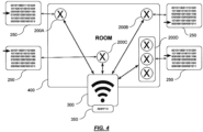
- Each of the lighting units (200A,200B,200C.200D), are located in a common lighting area such as a room (400) of a building.
- Figure. 2 shows an exemplary functional block diagram of each of the lighting units (200A,200B,200C,200D) which for ease of understanding of this embodiment are functionally identical in configuration and operation.
- the lighting units (200A, 200B, 200C.200D) each comprise a communication module (210) for wireless communicating with external devices such as the control unit (300), a memory module (220) for storing data code sequences and program code used to output at least one dynamic lighting scene, an illumination module (230) for outputting the steps of a dynamic lighting scene selected by the user, and, a processor module (240) for executing program code instructions stored in the memory module (220) to effect output of the at least one dynamic lighting scene.
- the processor modules and/or the memory modules of the lighting units may be provided by way of a centralised processor module and/or a centralised memory module that are located in only one of the lighting units within the group, or, in an entirely separate device to each of the lighting units.
- the centralised processor module and/or memory module would be operably connected to each of the lighting units in the group via a wired or wireless communication link so as to provide centralised functionality for each of the lighting units.
- the illumination modules (230) of the lighting units (200A,200B,200C,200D) can comprise any suitabletype of lighting technology however in this embodiment is comprised by a combination of an RGB, white light LED lighting, and brightness dimming modules configured to output a range of colour temperatures, white light components, and brightness characteristics defined by data code sequence representing the sequential steps of the dynamic lighting scene.
- the communication module (210) of each of the lighting devices (200A,200B,200C,200D) comprises a Wi-Fi protocol compatible communication module whereby the control unit is able to communicate control signals to the lighting units via a Wi-Fi router.
- wireless communication to and from the lighting units (200A, 2008, 200C) may instead be effected using a Bluetooth, Infrared, or other suitable radio frequency signaling protocol.
- it is possible that communication between the lighting units and external devices such as the control unit may even be implemented via a wired communication link if so desired.
- the memory modules (220) of the lighting units (200A, 200B. 200C,200D) may include for instance a flash memory module (220) for storing the data code sequence and program code.
- the data code sequence represents different ROB, white light and brightness characteristics associated with each of the sequential steps comprising the at least one dynamic lighting scene.
- the program code comprises computer readable instructions that are executable by the processor module (240) so as to operably control the illumination module (230) to output the lighting characteristics of the steps of the dynamic lighting scene as defined by the data code sequence of the dynamic lighting scene.
- the memory modules (2230) of the lighting units (200A,200B,200C,200D) will typically store a plurality of different data code sequences representing a variety of different dynamic lighting scenes so that the user has the flexibility to select a suitable dynamic lighting scene to be output depending upon the specific mood and requirements of the user.
- the data code sequences and program code may be preprogrammed into the memory modules (220) at the time of manufacture, and/or, may be automatically or manually downloadable into the memory modules (220) from for instance a remote server in communication with the lighting units (200A,2008,200C,200D) via their communication modules (210).
- this allows for new data code sequences representing newly created dynamic lighting scenes to be shared into the lighting units (200A,200B,200C,200D) so that the user is presented with an even broader range of available selections over time.
- the plurality of lighting units (200A,200B,200C,200D) are configured to process the same data code sequence (250) representing the same dynamic lighting scene selected by the user so that the respective illumination modules output the dynamic lighting scene together.
- the control device (300) communicates the selection to each of the plurality of lighting units (200A,200B,200C,200D) via the wireless communication link.
- Each of the plurality lighting units (200A,200B,200C,200D) will receive the control input (300) via their respective communication modules (210 ⁇ , and responsive to the received control input, the respective processor modules (240) of the lighting units (200A, 2008, 200C,200D) will execute the program code stored in the respective memory modules (220) so as to process the data code sequence representing the dynamic lighting scene selected by the user.
- the plurality of lighting scenes are also configured to output the selected dynamic lighting scene in a non-synchronous manner whereby they each commence outputting the selected dynamic lighting scene at different and/or random steps in the sequence of steps comprising the dynamic lighting scene.
- each lighting unit (200A,200B,200C,200D) commencing outputting of the dynamic lighting scene at different steps in the sequence The determination as to which step in the sequence each lighting unit commences outputting of the dynamic lighting scene can for instance be achieved by the executable program code being configured to assign numerical values to each of the steps in the dynamic lighting scene and then randomly picking the starting step for each lighting unit by reference to numerical values output by a pseudorandom number generator algorithm.
- the control unit (300) may include a processor module configured for randomly determining different steps of the sequence at which each of the plurality of lighting units will commence outputting the dynamic lighting scene in a non- synchronous manner.
- the processor module (310) of the control unit (300) may also utilise a pseudorandom number generator algorithm to randomly make this determination. Thereafter, when the control unit (300) wirelessly communicates a control instruction code (350) identifying the dynamic lighting scene selected by the user to each of the plurality of lighting units (200A, 2008, 200C,200D), the control instruction code (350) may also be encoded with instructions to each of the plurality of lighting units (200A, 200B, 200C,200D) as to the steps at which each of the lighting units is to commence outputting of the dynamic lighting scene, as randomly determined by the control unit (300).
- Each of the plurality of lighting units (200A, 2008, 200C,200D) will typically have a unique identifier code such as a MAC address associated therewith and the control unit is able to encode control instructions directed to each of the plurality of lighting units (200A, 2008, 200C,200D) in a single transmitted control signal by - referencing the unique identifier codes of each of the lighting units (200A, 2008, 200C,200D).
- a unique identifier code such as a MAC address
- the program code is further configured to randomise the manner in which one or more output parameters of each step in the sequence of the selected dynamic lighting scene is output.
- the program code may be configured to randomly vary at least one of the following output parameters of each step in the sequence:
- the randomisation of the above exemplary output parameters of each of the steps can be achieved using a pseudorandom number generator algorithm implemented by the processor modules (230) of the respective lighting units (200A,200B,200C,200D) whereby the parameters are variable by reference to the random values generated by the algorithms.
- the randomness of each of the above output parameters may be predefined into the program code executable by the respective processor modules (230) of each of the lighting units (200A,200B,200C).
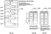
- Fig. 6A an example of the process flow and random output of steps of a dynamic lighting scene is shown whereby the data code sequence (250) comprises 6 steps (250A-250F) each of which may be randomly output by the lighting unit (2008).
- the data code sequence (250) comprises 6 steps (250A-250F) each of which may be randomly output by the lighting unit (2008).
- step 1 (250A) has been randomly output by the illumination module of lighting unit (200B)
- step 2 (250B) is randomly skipped over for output by lighting unit (2008) whereby step 3 (250C) is randomly output instead.
- a different lighting unit (200A) in the group randomly outputs step 2 (250B).
- step 4 (250D) is randomly skipped over by lighting unit (2008) whereby step 5 (250E) is randomly output instead.
- lighting unit (200A) in the group randomly outputs step 4 (250D) but randomly skips over outputting step 5 (250E) instead.
- the randomisation of the output parameters associated with each step of the dynamic lighting scene may assist in creating a more immersive and pleasant visual rendering of the dynamic lighting scene for the user than compared to the relatively repetitive and predictable manner in which the sequential steps in a dynamic lighting scenes are rendered by existing systems.
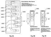
- the dynamic lighting scenes may include one or more "micro-scenes" - that is, a predefined group of sequential steps within the dynamic lighting scene.
- Micro-scenes are designed so that the combined output of the associated steps when output sequentially by the illumination modules (240) may simulate a particular effect - for instance, a dramatic flash of lighting.
- the program is configured so that when a first step of a micro-scene is randomly skipped over by the program, the program is configured to also automatically skip over all other steps pre-defined in the micro-scene and to output the next step immediately following the steps in the micro-scene. Conversely, when the first step in the micro-scene (251) is randomly output by the program, all other steps in the micro-scene are also then automatically output by the program.
- FIG. SA an example micro-scene (251) is shown comprised of a pre-defined grouping of 3 steps - that is, the micro-scene (251) comprises steps 4 (250D), 5 (250E) and 6 (250F) within the data code sequence (250) comprising an overall 6 steps (250A-250G).
- Figure 5B shows an example of where the lighting unit (200A) has randomly skipped over the first step (i.e.
- step 4 (250D)) of the micro-scene and consequently, the processor module of the lighting unit (200A) is configured to automatically skip over all other remaining steps 5 (250E) and 6 (250F) of the micro-scene (251).
- the processor module of the lighting unit (200A) is configured to also automatically output over all other remaining steps 5 (250E) and 6 (250F) of the micro-scene (251).
- control unit (3) could comprise for example an application specific remote control device, a smartphone, a tablet device or a personal computer having an input user interface (330), a memory module (320), a processor module (310) and a wireless communication module (340) operably-connected together.
- the user input interface (330) may typically include a touchscreen electronic display module (340) which is configured to display a menu listing of predefined dynamic lighting scenes entries thereon. The user may select any one of the predefined dynamic lighting scenes from the menu listing by effecting touch interaction with the appropriate entry in the menu listing on the display screen.
- the processor module (310) of the control unit (300) is then configured to transmit a control signal instruction to the lighting units (200A,200B,200C,200D) which is indicative of the selected menu entry.
- the input user interface (3330) may be a separate input device such as a physical keypad, touchpad or mouse type device interface.
- a software application module is downloadable into the memory module (320) of the control unit (300) from an online computer server via the communication network and is executable by the processor module (310) of the control unit (300) to provide a graphical user- interface (330) operable on the touchscreen electronic display module (330) via which a user may be able to at least provide various user-interactive control.
- the various user-interactive control provided by the software application module may be implemented by embedded software disposed in the hardware itself or any other suitable hardware technology.
- the software application module is further configured to allow operable connection with each of the lighting units (200A,200B,200C,200D) in the communication network via respective communication modules (210) of each of the lighting units (200A,2008,200C,200D), to recognise each of the lighting units (200A,200B,200C,200D) by reference to their respective unique identifiers, and to control operation of each of the lighting unit settings of each of the lighting units (200A,200B,200C,200D).
- exemplary method steps (100)-(130) are shown in the flowchart of Fig. 1 for outputting a dynamic lighting scene by a group of lighting units, whereby the method steps are broadly as follows:
- Any one of the functional modules of the embodiments described herein may be implemented by way of software for execution by various types of processors.
- Executable code may, for instance, comprise one or more physical or logical blocks of computer instructions which may, for instance, be organised as an object, procedure, function, or algorithm.
- the identified blocks of computer instructions need not be physically located together, but may comprise disparate instructions stored in different locations which, when joined logically together, comprise the module and achieve the stated purpose for the module.
- Functional modules of the embodiments may also be implemented as hardware circuitry comprising custom circuits or gate arrays, off-the-shelf semiconductors such as logic chips, transistors, or other discrete components.
- Functional modules may also be implemented in programmable hardware devices such as field programmable gate arrays, programmable array logic, programmable logic devices or the like.
- Executable code may comprise a single instruction, multiple instructions, and may be distributed over several different code segments, among different programs, and across several discrete memory devices.
- operational data may be identified and illustrated herein within devices, units, and the like and may be embodied in any suitable form and organised within any suitable type of data structure. The operational data may be collected as a single data set, or may be distributed over different locations including over different storage devices, and may exist, at least partially, merely as electronic signals on a system or network.
Landscapes
- Engineering & Computer Science (AREA)
- Computer Networks & Wireless Communication (AREA)
- Circuit Arrangement For Electric Light Sources In General (AREA)
Claims (9)
- System zum Steuern einer Ausgabe einer dynamischen Beleuchtungsszene durch eine erste und eine zweite Beleuchtungseinheit innerhalb eines gemeinsamen Beleuchtungsbereichs, das System umfassend:die erste Beleuchtungseinheit (200A);die zweite Beleuchtungseinheit (200B);mindestens ein Speichermodul (220), das zum Speichern einer Datencodesequenz konfiguriert ist, die vordefinierte Beleuchtungseigenschaften, die mit einer Vielzahl von sequenziellen Schritten der dynamischen Beleuchtungsszene verknüpft sind, darstellt, wobei die Vielzahl von sequenziellen Schritten eine Sequenz von Schritten ist;mindestens ein Prozessormodul (230), das zum Verarbeiten der Datencodesequenz konfiguriert ist, um aus der Datencodesequenz die Beleuchtungseigenschaften, die mit der Vielzahl von sequenziellen Schritten verknüpft sind, zu bestimmen,wobei jede der ersten und der zweiten Beleuchtungseinheit umfasstein Illuminationsmodul (240), das zum Ausgeben der Beleuchtungseigenschaften konfiguriert ist, die mit der Vielzahl von sequenziellen Schritten der dynamischen Beleuchtungsszene, wie durch das mindestens eine Prozessormodul (230) bestimmt, verknüpft sind undwobei die Illuminationsmodule (240) der ersten und der zweiten Beleuchtungseinheit zum Ausgeben der Beleuchtungseigenschaften der Vielzahl von sequenziellen Schritten der dynamischen Beleuchtungsszene in einer im Wesentlichen nicht synchronen Weise konfiguriert sind,wobei mindestens eines der Illuminationsmodule (240) der ersten und der zweiten Beleuchtungseinheit zum Ausgeben der Beleuchtungseigenschaften, die mit den Schritten in der Sequenz von Schritten der dynamischen Beleuchtungsszene in einer im Wesentlichen zufällig angeordneten Weise verknüpft sind, konfiguriert ist, gekennzeichnet durch:wobei die Illuminationsmodule (240) der ersten und der zweiten Beleuchtungseinheit konfiguriert sind, um die Zeitdauer der Ausgabe mindestens eines der Schritte in der Sequenz von Schritten der dynamischen Beleuchtungsszene zufällig zu ändern;wobei mindestens ein erster und ein zweiter sequenzieller Schritt in der Sequenz von Schritten der dynamischen Beleuchtungsszene miteinander verknüpft sind und wobei, wenn der erste Schritt während des Ausgebens der dynamischen Beleuchtungsszene zufällig ausgegeben wird, die Illuminationsmodule (240) der ersten und der zweiten Beleuchtungseinheit konfiguriert sind, um ebenso den zweiten sequenziellen Schritt, der mit dem ersten Schritt verknüpft ist, automatisch auszugeben.
- System nach Anspruch 1, wobei die Illuminationsmodule (240) der ersten und der zweiten Beleuchtungseinheit zum Ausgeben der dynamischen Beleuchtungsszene beginnend bei unterschiedlichen Schritten in der Sequenz von Schritten der dynamischen Beleuchtungsszene konfiguriert sind.
- System nach einem der vorstehenden Ansprüche, wobei die Illuminationsmodule (240) der ersten und der zweiten Beleuchtungseinheit mindestens eines von einer farbigen LED, einer Weißlicht-LED und einem Helligkeitsdimmmodul einschließen, die zum Ausgeben der Beleuchtungseigenschaften, die mit der Vielzahl von sequenziellen Schritten der dynamischen Beleuchtungsszene verknüpft sind, konfiguriert sind.
- System nach einem der vorstehenden Ansprüche, wobei jede der ersten und der zweiten Beleuchtungseinheit eines der mindestens einen Prozessormodule (230) umfasst und/oder wobei jede der ersten und der zweiten Beleuchtungseinheit eines der mindestens einen Speichermodule (220) umfasst.
- System nach einem der vorstehenden Ansprüche, wobei das mindestens eine Speichermodul (220) zum Speichern einer Vielzahl von Datencodesequenzen konfiguriert ist, die je vordefinierte Beleuchtungseigenschaften darstellen, die mit einer Vielzahl von sequenziellen Schritten einer Vielzahl von unterschiedlichen dynamischen Beleuchtungsszenen, die durch die Illuminationsmodule (240) der ersten und der zweiten Beleuchtungseinheit ausgegeben werden können, verknüpft sind.
- System nach Anspruch 5, das eine Steuereinheit einschließt, die zum Steuern der Illuminationsmodule (240) der ersten und der zweiten Beleuchtungseinheit konfiguriert ist, um eine der Vielzahl von dynamischen Beleuchtungsszenen auswählbar auszugeben, die durch eine der Vielzahl von Datencodesequenzen, die in dem mindestens einen Speichermodul (220) gespeichert ist, dargestellt wird.
- System nach Anspruch 6, wobei die Steuereinheit zum Steuern der Illuminationsmodule (240) der ersten und der zweiten Beleuchtungseinheit durch Kommunizieren eines drahtlosen Steuersignals an mindestens eine der ersten und der zweiten Beleuchtungseinheit über eine drahtlose Kommunikationsverbindung konfiguriert ist, wobei das drahtlose Steuersignal Informationen einschließt, die eine der Vielzahl von dynamischen Beleuchtungsszenen angeben, die ausgewählt wird, um ausgegeben zu werden.
- Verfahren zum Steuern der Ausgabe einer dynamischen Beleuchtungsszene durch eine erste und eine zweite Beleuchtungseinheit (200A, 200B) innerhalb eines gemeinsamen Beleuchtungsbereichs, das Verfahren umfassend die Schritte:(i) Speichern einer Datencodesequenz, die vordefinierte Beleuchtungseigenschaften, die mit einer Vielzahl von sequenziellen Schritten der dynamischen Beleuchtungsszene in mindestens einem Speichermodul (220) verknüpft sind, darstellt, wobei die Vielzahl von sequenziellen Schritten eine Sequenz von Schritten ist;(ii) Verwenden eines Prozessormoduls (230), um die Datencodesequenz zu verarbeiten, um aus der Datencodesequenz die Beleuchtungseigenschaften, die mit der Vielzahl von sequenziellen Schritten verknüpft sind, zu bestimmen; und(iii) Ausgeben der Beleuchtungseigenschaften, die mit der Vielzahl von sequenziellen Schritten der dynamischen Beleuchtungsszene verknüpft sind, wie durch das mindestens eine Prozessormodul über Illuminationsmodule (240) jeder der ersten und der zweiten Beleuchtungseinheit bestimmt;wobei die Illuminationsmodule (240) der ersten und der zweiten Beleuchtungseinheit zum Ausgeben der Beleuchtungseigenschaften der Vielzahl von sequenziellen Schritten der dynamischen Beleuchtungsszene in einer im Wesentlichen nicht synchronen Weise konfiguriert sind;wobei mindestens eines der Illuminationsmodule (240) der ersten und der zweiten Beleuchtungseinheit zum Ausgeben der Beleuchtungseigenschaften, die mit den Schritten in der Sequenz von Schritten der dynamischen Beleuchtungsszene in einer im Wesentlichen zufällig angeordneten Weise verknüpft sind, konfiguriert ist, gekennzeichnet durch:wobei die Illuminationsmodule (240) der ersten und der zweiten Beleuchtungseinheit konfiguriert sind, um die Zeitdauer der Ausgabe mindestens eines der Schritte in der Sequenz von Schritten der dynamischen Beleuchtungsszene zufällig zu ändern;wobei mindestens ein erster und ein zweiter sequenzieller Schritt in der Sequenz von Schritten der dynamischen Beleuchtungsszene miteinander verknüpft sind und wobei, wenn der erste Schritt während des Ausgebens der dynamischen Beleuchtungsszene zufällig ausgegeben wird, die Illuminationsmodule (240) der ersten und der zweiten Beleuchtungseinheit konfiguriert sind, um ebenso den zweiten sequenziellen Schritt, der mit dem ersten Schritt verknüpft ist, automatisch auszugeben
- Verfahren nach Anspruch 8, wobei die Illuminationsmodule (240) der ersten und der zweiten Beleuchtungseinheit zum Ausgeben der dynamischen Beleuchtungsszene beginnend bei unterschiedlichen Schritten in der Sequenz von Schritten der dynamischen Beleuchtungsszene konfiguriert sind.
Applications Claiming Priority (1)
| Application Number | Priority Date | Filing Date | Title |
|---|---|---|---|
| PCT/CN2017/098654 WO2019036934A1 (en) | 2017-08-23 | 2017-08-23 | SYSTEM AND METHOD FOR EXIT CONTROL OF A DYNAMIC LIGHTING SCENE BY A GROUP OF LIGHTING UNITS |
Publications (3)
| Publication Number | Publication Date |
|---|---|
| EP3673716A4 EP3673716A4 (de) | 2020-07-01 |
| EP3673716A1 EP3673716A1 (de) | 2020-07-01 |
| EP3673716B1 true EP3673716B1 (de) | 2024-08-07 |
Family
ID=65438353
Family Applications (1)
| Application Number | Title | Priority Date | Filing Date |
|---|---|---|---|
| EP17922694.9A Active EP3673716B1 (de) | 2017-08-23 | 2017-08-23 | System und verfahren zur steuerung der ausgabe einer dynamischen beleuchtungsszene durch eine gruppe von beleuchtungseinheiten |
Country Status (4)
| Country | Link |
|---|---|
| US (1) | US11337289B2 (de) |
| EP (1) | EP3673716B1 (de) |
| CN (1) | CN111034360B (de) |
| WO (1) | WO2019036934A1 (de) |
Families Citing this family (2)
| Publication number | Priority date | Publication date | Assignee | Title |
|---|---|---|---|---|
| US11337289B2 (en) * | 2017-08-23 | 2022-05-17 | Signify Holding B.V. | System and method for controlling output of a dynamic lighting scene by a group of lighting units |
| EP3800968B1 (de) * | 2018-07-17 | 2026-04-08 | Suzhou Opple Lighting Co., Ltd. | Intelligente steuerungsvorrichtung für leuchte |
Family Cites Families (39)
| Publication number | Priority date | Publication date | Assignee | Title |
|---|---|---|---|---|
| US5924784A (en) * | 1995-08-21 | 1999-07-20 | Chliwnyj; Alex | Microprocessor based simulated electronic flame |
| US7231060B2 (en) * | 1997-08-26 | 2007-06-12 | Color Kinetics Incorporated | Systems and methods of generating control signals |
| US20020113555A1 (en) * | 1997-08-26 | 2002-08-22 | Color Kinetics, Inc. | Lighting entertainment system |
| US6869204B2 (en) * | 1997-08-26 | 2005-03-22 | Color Kinetics Incorporated | Light fixtures for illumination of liquids |
| US7242152B2 (en) * | 1997-08-26 | 2007-07-10 | Color Kinetics Incorporated | Systems and methods of controlling light systems |
| US7038398B1 (en) * | 1997-08-26 | 2006-05-02 | Color Kinetics, Incorporated | Kinetic illumination system and methods |
| US6016038A (en) * | 1997-08-26 | 2000-01-18 | Color Kinetics, Inc. | Multicolored LED lighting method and apparatus |
| US20040052076A1 (en) * | 1997-08-26 | 2004-03-18 | Mueller George G. | Controlled lighting methods and apparatus |
| CA2335401A1 (en) * | 2000-02-14 | 2001-08-14 | Alex Chliwnyj | Electronic flame |
| US6688752B2 (en) * | 2001-10-11 | 2004-02-10 | Wayne T. Moore | Electronically simulated flame |
| US9955551B2 (en) * | 2002-07-12 | 2018-04-24 | Yechezkal Evan Spero | Detector controlled illuminating system |
| CN100517145C (zh) * | 2003-06-10 | 2009-07-22 | 卢特龙电子公司 | 用于rf受控照明系统的系统桥接器和时钟 |
| JP2008527446A (ja) * | 2005-01-06 | 2008-07-24 | エス.シー. ジョンソン アンド サン、インコーポレイテッド | ライトショーを保存・定義する方法および装置 |
| US20060208666A1 (en) * | 2005-03-16 | 2006-09-21 | Johnson David C | Electronic lighting device for simulating a flame |
| CA2972780C (en) * | 2005-04-08 | 2020-04-28 | Eldolab Holding B.V. | Methods and apparatuses for operating groups of high-power leds |
| EP1894075A4 (de) * | 2005-06-06 | 2008-06-25 | Color Kinetics Inc | Verfahren und vorrichtung zur implementierung einer leistungszyklussteuerung für beleuchtungsvorrichtungen auf der basis von netzwerkprotokollen |
| WO2009076493A2 (en) * | 2007-12-13 | 2009-06-18 | Daniel John Julio | Random algorithmic color selection for lighting |
| EP2120512A1 (de) * | 2008-05-13 | 2009-11-18 | Koninklijke Philips Electronics N.V. | Stochastische dynamische Atmosphäre |
| WO2010036869A2 (en) * | 2008-09-25 | 2010-04-01 | Lumination Llc | Adjustable color illumination source |
| CN201652146U (zh) * | 2010-05-06 | 2010-11-24 | 胡明川 | 一种梅花形的led节能彩色水底灯 |
| GB2495324B (en) * | 2011-10-07 | 2018-05-30 | Irisguard Inc | Security improvements for Iris recognition systems |
| AT13736U1 (de) * | 2011-10-27 | 2014-07-15 | Tridonic Gmbh & Co Kg | Pwm-dimmen von leuchtmitteln |
| US9496793B2 (en) * | 2011-11-01 | 2016-11-15 | Azoteq (Pty) Ltd | Capacitive sensing enabled switch mode power supply and data transfer |
| WO2014186808A2 (en) * | 2013-05-17 | 2014-11-20 | Barry Thornton | Security and first-responder emergency lighting system |
| CN103607823B (zh) | 2013-11-27 | 2019-01-04 | 嘉兴市创杰电子科技有限公司 | 一种led发光装置 |
| JP6605488B2 (ja) * | 2014-03-06 | 2019-11-13 | シグニファイ ホールディング ビー ヴィ | 予測保全スケジューリングを用いたインテリジェント照明システム及びその動作方法 |
| JP6410076B2 (ja) * | 2014-03-28 | 2018-10-24 | シーシーエス株式会社 | 電源装置及びled照明装置 |
| CN103987176A (zh) * | 2014-05-22 | 2014-08-13 | 上海宝昂电子科技发展有限公司 | 灯光控制设备 |
| JP6390885B2 (ja) * | 2015-05-29 | 2018-09-19 | パナソニックIpマネジメント株式会社 | 照明演出システム及びプログラム |
| EP3198997B1 (de) * | 2015-12-03 | 2019-02-20 | Wizconnected Company Limited | System und verfahren zur steuerung einer gruppe von beleuchtungseinheiten |
| WO2017148767A1 (en) * | 2016-03-02 | 2017-09-08 | Philips Lighting Holding B.V. | Lighting scene selection based on operation of one or more individual light sources |
| ES2729028T3 (es) * | 2016-03-11 | 2019-10-29 | Wiz Connected Lighting Co Ltd | Un sistema y método de iluminación configurable |
| EP3238509B1 (de) * | 2016-03-11 | 2025-02-26 | Signify Holding B.V. | System zur bedienung von mehreren beleuchtungseinheiten in einem gebäude |
| CN106170168A (zh) * | 2016-07-06 | 2016-11-30 | 太仓诚泽网络科技有限公司 | 一种舞台灯光场景效果智能控制系统 |
| US10440794B2 (en) * | 2016-11-02 | 2019-10-08 | LIFI Labs, Inc. | Lighting system and method |
| KR20190082305A (ko) * | 2016-11-18 | 2019-07-09 | 광둥 라이트 비주얼 헬스 리서치 인스티튜트 | 모니터 발광 파라미터 동태 조절 방법 및 디스플레이장치 |
| EP3544387A4 (de) * | 2016-11-18 | 2020-06-24 | Guangdong Wlight Visual Health Research Institute | Dynamisches beleuchtungsverfahren und vorrichtung |
| US11337289B2 (en) * | 2017-08-23 | 2022-05-17 | Signify Holding B.V. | System and method for controlling output of a dynamic lighting scene by a group of lighting units |
| US10820395B2 (en) * | 2017-08-29 | 2020-10-27 | Abl Ip Holding Llc | Methods for operating mechatronic transforming luminaire swarms |
-
2017
- 2017-08-23 US US16/641,374 patent/US11337289B2/en active Active
- 2017-08-23 WO PCT/CN2017/098654 patent/WO2019036934A1/en not_active Ceased
- 2017-08-23 CN CN201780094161.3A patent/CN111034360B/zh active Active
- 2017-08-23 EP EP17922694.9A patent/EP3673716B1/de active Active
Also Published As
| Publication number | Publication date |
|---|---|
| EP3673716A4 (de) | 2020-07-01 |
| CN111034360A (zh) | 2020-04-17 |
| US11337289B2 (en) | 2022-05-17 |
| CN111034360B (zh) | 2022-08-02 |
| EP3673716A1 (de) | 2020-07-01 |
| US20200196425A1 (en) | 2020-06-18 |
| WO2019036934A1 (en) | 2019-02-28 |
Similar Documents
| Publication | Publication Date | Title |
|---|---|---|
| CN109792822B (zh) | 照明控制的方法和系统 | |
| US20180295699A1 (en) | Method and system for controlling the switching on of lights | |
| US10952305B2 (en) | Configurable lighting system and method comprising a programmable control module that controls a plurality of different patterns based on toggling a power supply | |
| US20180092187A1 (en) | Lighting setting apparatus and lighting system | |
| EP4055998B1 (de) | Definition einer oder mehrerer gruppen in einem konfigurierbaren system basierend auf vorrichtungsnamenähnlichkeit | |
| CN112042280B (zh) | 用于控制多个照明设备的方法和照明控制设备 | |
| EP3673716B1 (de) | System und verfahren zur steuerung der ausgabe einer dynamischen beleuchtungsszene durch eine gruppe von beleuchtungseinheiten | |
| JP2023155287A (ja) | 無線通信装置、無線通信システム、制御システム、負荷制御システム、データ送信方法およびプログラム | |
| CN114902810A (zh) | 用于为多个照明单元生成光设置的控制器及其方法 | |
| AU2019210205A1 (en) | System, apparatus and method for wireless transmission of control data | |
| US20200100344A1 (en) | Illumination system and method for setting up illumination system | |
| JP6704191B2 (ja) | 照明システム、その設定方法、及び端末装置 | |
| JP6934578B2 (ja) | 照明システム | |
| JP2016149326A (ja) | 照明制御システム、照明制御方法および照明制御プログラム | |
| KR102462007B1 (ko) | 시나리오 액티베이션 기반 라이팅 장치와 이를 제어하는 제어 장치 및 방법 | |
| TW201922055A (zh) | 照明系統及控制器 | |
| EP3198997A1 (de) | System und verfahren zur steuerung einer gruppe von beleuchtungseinheiten | |
| JP2018006062A (ja) | 照明制御システム | |
| EP3387879B1 (de) | Ableitung eines weissen flecks zur verwendung in einer mehrfarbigen lichtszene | |
| CN113196882B (zh) | 用于配置照明系统的控制系统及其方法 | |
| US20190297711A1 (en) | A device, system and method for controlling operation of lighting units | |
| CN105704888A (zh) | 控制照明元件的方法和相关系统 | |
| JP2023170788A (ja) | 照明器具、照明システム及び制御方法 | |
| JP2017004618A (ja) | スケジュールコントローラ、照明システム及び照明制御方法 | |
| JP2017062900A (ja) | 制御装置及び照明制御方法 |
Legal Events
| Date | Code | Title | Description |
|---|---|---|---|
| STAA | Information on the status of an ep patent application or granted ep patent |
Free format text: STATUS: THE INTERNATIONAL PUBLICATION HAS BEEN MADE |
|
| PUAI | Public reference made under article 153(3) epc to a published international application that has entered the european phase |
Free format text: ORIGINAL CODE: 0009012 |
|
| STAA | Information on the status of an ep patent application or granted ep patent |
Free format text: STATUS: REQUEST FOR EXAMINATION WAS MADE |
|
| 17P | Request for examination filed |
Effective date: 20200323 |
|
| A4 | Supplementary search report drawn up and despatched |
Effective date: 20200526 |
|
| AK | Designated contracting states |
Kind code of ref document: A1 Designated state(s): AL AT BE BG CH CY CZ DE DK EE ES FI FR GB GR HR HU IE IS IT LI LT LU LV MC MK MT NL NO PL PT RO RS SE SI SK SM TR |
|
| AX | Request for extension of the european patent |
Extension state: BA ME |
|
| DAV | Request for validation of the european patent (deleted) | ||
| DAX | Request for extension of the european patent (deleted) | ||
| STAA | Information on the status of an ep patent application or granted ep patent |
Free format text: STATUS: EXAMINATION IS IN PROGRESS |
|
| 17Q | First examination report despatched |
Effective date: 20210705 |
|
| RAP1 | Party data changed (applicant data changed or rights of an application transferred) |
Owner name: SIGNIFY HOLDING B.V. |
|
| REG | Reference to a national code |
Ref country code: DE Ipc: H05B0047155000 Ref country code: DE Ref legal event code: R079 Ref document number: 602017083990 Country of ref document: DE Free format text: PREVIOUS MAIN CLASS: H05B0047160000 Ipc: H05B0047155000 |
|
| RIC1 | Information provided on ipc code assigned before grant |
Ipc: H05B 47/165 20200101ALI20230901BHEP Ipc: H05B 47/16 20200101ALI20230901BHEP Ipc: H05B 47/19 20200101ALI20230901BHEP Ipc: H05B 47/155 20200101AFI20230901BHEP |
|
| GRAP | Despatch of communication of intention to grant a patent |
Free format text: ORIGINAL CODE: EPIDOSNIGR1 |
|
| STAA | Information on the status of an ep patent application or granted ep patent |
Free format text: STATUS: GRANT OF PATENT IS INTENDED |
|
| INTG | Intention to grant announced |
Effective date: 20231102 |
|
| GRAJ | Information related to disapproval of communication of intention to grant by the applicant or resumption of examination proceedings by the epo deleted |
Free format text: ORIGINAL CODE: EPIDOSDIGR1 |
|
| STAA | Information on the status of an ep patent application or granted ep patent |
Free format text: STATUS: EXAMINATION IS IN PROGRESS |
|
| GRAP | Despatch of communication of intention to grant a patent |
Free format text: ORIGINAL CODE: EPIDOSNIGR1 |
|
| STAA | Information on the status of an ep patent application or granted ep patent |
Free format text: STATUS: GRANT OF PATENT IS INTENDED |
|
| INTC | Intention to grant announced (deleted) | ||
| INTG | Intention to grant announced |
Effective date: 20240305 |
|
| GRAS | Grant fee paid |
Free format text: ORIGINAL CODE: EPIDOSNIGR3 |
|
| GRAA | (expected) grant |
Free format text: ORIGINAL CODE: 0009210 |
|
| STAA | Information on the status of an ep patent application or granted ep patent |
Free format text: STATUS: THE PATENT HAS BEEN GRANTED |
|
| P01 | Opt-out of the competence of the unified patent court (upc) registered |
Free format text: CASE NUMBER: APP_37839/2024 Effective date: 20240625 |
|
| AK | Designated contracting states |
Kind code of ref document: B1 Designated state(s): AL AT BE BG CH CY CZ DE DK EE ES FI FR GB GR HR HU IE IS IT LI LT LU LV MC MK MT NL NO PL PT RO RS SE SI SK SM TR |
|
| REG | Reference to a national code |
Ref country code: GB Ref legal event code: FG4D |
|
| REG | Reference to a national code |
Ref country code: CH Ref legal event code: EP |
|
| REG | Reference to a national code |
Ref country code: IE Ref legal event code: FG4D |
|
| REG | Reference to a national code |
Ref country code: DE Ref legal event code: R096 Ref document number: 602017083990 Country of ref document: DE |
|
| REG | Reference to a national code |
Ref country code: LT Ref legal event code: MG9D |
|
| REG | Reference to a national code |
Ref country code: NL Ref legal event code: MP Effective date: 20240807 |
|
| PG25 | Lapsed in a contracting state [announced via postgrant information from national office to epo] |
Ref country code: NO Free format text: LAPSE BECAUSE OF FAILURE TO SUBMIT A TRANSLATION OF THE DESCRIPTION OR TO PAY THE FEE WITHIN THE PRESCRIBED TIME-LIMIT Effective date: 20241107 |
|
| REG | Reference to a national code |
Ref country code: AT Ref legal event code: MK05 Ref document number: 1712310 Country of ref document: AT Kind code of ref document: T Effective date: 20240807 |
|
| PG25 | Lapsed in a contracting state [announced via postgrant information from national office to epo] |
Ref country code: FI Free format text: LAPSE BECAUSE OF FAILURE TO SUBMIT A TRANSLATION OF THE DESCRIPTION OR TO PAY THE FEE WITHIN THE PRESCRIBED TIME-LIMIT Effective date: 20240807 Ref country code: NL Free format text: LAPSE BECAUSE OF FAILURE TO SUBMIT A TRANSLATION OF THE DESCRIPTION OR TO PAY THE FEE WITHIN THE PRESCRIBED TIME-LIMIT Effective date: 20240807 Ref country code: GR Free format text: LAPSE BECAUSE OF FAILURE TO SUBMIT A TRANSLATION OF THE DESCRIPTION OR TO PAY THE FEE WITHIN THE PRESCRIBED TIME-LIMIT Effective date: 20241108 Ref country code: PT Free format text: LAPSE BECAUSE OF FAILURE TO SUBMIT A TRANSLATION OF THE DESCRIPTION OR TO PAY THE FEE WITHIN THE PRESCRIBED TIME-LIMIT Effective date: 20241209 Ref country code: PL Free format text: LAPSE BECAUSE OF FAILURE TO SUBMIT A TRANSLATION OF THE DESCRIPTION OR TO PAY THE FEE WITHIN THE PRESCRIBED TIME-LIMIT Effective date: 20240807 |
|
| PG25 | Lapsed in a contracting state [announced via postgrant information from national office to epo] |
Ref country code: BG Free format text: LAPSE BECAUSE OF FAILURE TO SUBMIT A TRANSLATION OF THE DESCRIPTION OR TO PAY THE FEE WITHIN THE PRESCRIBED TIME-LIMIT Effective date: 20240807 |
|
| PG25 | Lapsed in a contracting state [announced via postgrant information from national office to epo] |
Ref country code: LV Free format text: LAPSE BECAUSE OF FAILURE TO SUBMIT A TRANSLATION OF THE DESCRIPTION OR TO PAY THE FEE WITHIN THE PRESCRIBED TIME-LIMIT Effective date: 20240807 |
|
| PG25 | Lapsed in a contracting state [announced via postgrant information from national office to epo] |
Ref country code: IS Free format text: LAPSE BECAUSE OF FAILURE TO SUBMIT A TRANSLATION OF THE DESCRIPTION OR TO PAY THE FEE WITHIN THE PRESCRIBED TIME-LIMIT Effective date: 20241207 Ref country code: AT Free format text: LAPSE BECAUSE OF FAILURE TO SUBMIT A TRANSLATION OF THE DESCRIPTION OR TO PAY THE FEE WITHIN THE PRESCRIBED TIME-LIMIT Effective date: 20240807 |
|
| PG25 | Lapsed in a contracting state [announced via postgrant information from national office to epo] |
Ref country code: HR Free format text: LAPSE BECAUSE OF FAILURE TO SUBMIT A TRANSLATION OF THE DESCRIPTION OR TO PAY THE FEE WITHIN THE PRESCRIBED TIME-LIMIT Effective date: 20240807 |
|
| PG25 | Lapsed in a contracting state [announced via postgrant information from national office to epo] |
Ref country code: ES Free format text: LAPSE BECAUSE OF FAILURE TO SUBMIT A TRANSLATION OF THE DESCRIPTION OR TO PAY THE FEE WITHIN THE PRESCRIBED TIME-LIMIT Effective date: 20240807 Ref country code: RS Free format text: LAPSE BECAUSE OF FAILURE TO SUBMIT A TRANSLATION OF THE DESCRIPTION OR TO PAY THE FEE WITHIN THE PRESCRIBED TIME-LIMIT Effective date: 20241107 |
|
| PG25 | Lapsed in a contracting state [announced via postgrant information from national office to epo] |
Ref country code: RS Free format text: LAPSE BECAUSE OF FAILURE TO SUBMIT A TRANSLATION OF THE DESCRIPTION OR TO PAY THE FEE WITHIN THE PRESCRIBED TIME-LIMIT Effective date: 20241107 Ref country code: PT Free format text: LAPSE BECAUSE OF FAILURE TO SUBMIT A TRANSLATION OF THE DESCRIPTION OR TO PAY THE FEE WITHIN THE PRESCRIBED TIME-LIMIT Effective date: 20241209 Ref country code: PL Free format text: LAPSE BECAUSE OF FAILURE TO SUBMIT A TRANSLATION OF THE DESCRIPTION OR TO PAY THE FEE WITHIN THE PRESCRIBED TIME-LIMIT Effective date: 20240807 Ref country code: NO Free format text: LAPSE BECAUSE OF FAILURE TO SUBMIT A TRANSLATION OF THE DESCRIPTION OR TO PAY THE FEE WITHIN THE PRESCRIBED TIME-LIMIT Effective date: 20241107 Ref country code: NL Free format text: LAPSE BECAUSE OF FAILURE TO SUBMIT A TRANSLATION OF THE DESCRIPTION OR TO PAY THE FEE WITHIN THE PRESCRIBED TIME-LIMIT Effective date: 20240807 Ref country code: LV Free format text: LAPSE BECAUSE OF FAILURE TO SUBMIT A TRANSLATION OF THE DESCRIPTION OR TO PAY THE FEE WITHIN THE PRESCRIBED TIME-LIMIT Effective date: 20240807 Ref country code: IS Free format text: LAPSE BECAUSE OF FAILURE TO SUBMIT A TRANSLATION OF THE DESCRIPTION OR TO PAY THE FEE WITHIN THE PRESCRIBED TIME-LIMIT Effective date: 20241207 Ref country code: HR Free format text: LAPSE BECAUSE OF FAILURE TO SUBMIT A TRANSLATION OF THE DESCRIPTION OR TO PAY THE FEE WITHIN THE PRESCRIBED TIME-LIMIT Effective date: 20240807 Ref country code: GR Free format text: LAPSE BECAUSE OF FAILURE TO SUBMIT A TRANSLATION OF THE DESCRIPTION OR TO PAY THE FEE WITHIN THE PRESCRIBED TIME-LIMIT Effective date: 20241108 Ref country code: FI Free format text: LAPSE BECAUSE OF FAILURE TO SUBMIT A TRANSLATION OF THE DESCRIPTION OR TO PAY THE FEE WITHIN THE PRESCRIBED TIME-LIMIT Effective date: 20240807 Ref country code: ES Free format text: LAPSE BECAUSE OF FAILURE TO SUBMIT A TRANSLATION OF THE DESCRIPTION OR TO PAY THE FEE WITHIN THE PRESCRIBED TIME-LIMIT Effective date: 20240807 Ref country code: BG Free format text: LAPSE BECAUSE OF FAILURE TO SUBMIT A TRANSLATION OF THE DESCRIPTION OR TO PAY THE FEE WITHIN THE PRESCRIBED TIME-LIMIT Effective date: 20240807 Ref country code: AT Free format text: LAPSE BECAUSE OF FAILURE TO SUBMIT A TRANSLATION OF THE DESCRIPTION OR TO PAY THE FEE WITHIN THE PRESCRIBED TIME-LIMIT Effective date: 20240807 |
|
| REG | Reference to a national code |
Ref country code: CH Ref legal event code: PL |
|
| PG25 | Lapsed in a contracting state [announced via postgrant information from national office to epo] |
Ref country code: SM Free format text: LAPSE BECAUSE OF FAILURE TO SUBMIT A TRANSLATION OF THE DESCRIPTION OR TO PAY THE FEE WITHIN THE PRESCRIBED TIME-LIMIT Effective date: 20240807 Ref country code: RO Free format text: LAPSE BECAUSE OF FAILURE TO SUBMIT A TRANSLATION OF THE DESCRIPTION OR TO PAY THE FEE WITHIN THE PRESCRIBED TIME-LIMIT Effective date: 20240807 Ref country code: DK Free format text: LAPSE BECAUSE OF FAILURE TO SUBMIT A TRANSLATION OF THE DESCRIPTION OR TO PAY THE FEE WITHIN THE PRESCRIBED TIME-LIMIT Effective date: 20240807 |
|
| PG25 | Lapsed in a contracting state [announced via postgrant information from national office to epo] |
Ref country code: LU Free format text: LAPSE BECAUSE OF NON-PAYMENT OF DUE FEES Effective date: 20240823 |
|
| PG25 | Lapsed in a contracting state [announced via postgrant information from national office to epo] |
Ref country code: EE Free format text: LAPSE BECAUSE OF FAILURE TO SUBMIT A TRANSLATION OF THE DESCRIPTION OR TO PAY THE FEE WITHIN THE PRESCRIBED TIME-LIMIT Effective date: 20240807 Ref country code: CH Free format text: LAPSE BECAUSE OF NON-PAYMENT OF DUE FEES Effective date: 20240831 |
|
| PG25 | Lapsed in a contracting state [announced via postgrant information from national office to epo] |
Ref country code: CZ Free format text: LAPSE BECAUSE OF FAILURE TO SUBMIT A TRANSLATION OF THE DESCRIPTION OR TO PAY THE FEE WITHIN THE PRESCRIBED TIME-LIMIT Effective date: 20240807 |
|
| PG25 | Lapsed in a contracting state [announced via postgrant information from national office to epo] |
Ref country code: SK Free format text: LAPSE BECAUSE OF FAILURE TO SUBMIT A TRANSLATION OF THE DESCRIPTION OR TO PAY THE FEE WITHIN THE PRESCRIBED TIME-LIMIT Effective date: 20240807 |
|
| REG | Reference to a national code |
Ref country code: DE Ref legal event code: R097 Ref document number: 602017083990 Country of ref document: DE |
|
| PLBE | No opposition filed within time limit |
Free format text: ORIGINAL CODE: 0009261 |
|
| STAA | Information on the status of an ep patent application or granted ep patent |
Free format text: STATUS: NO OPPOSITION FILED WITHIN TIME LIMIT |
|
| REG | Reference to a national code |
Ref country code: BE Ref legal event code: MM Effective date: 20240831 |
|
| PG25 | Lapsed in a contracting state [announced via postgrant information from national office to epo] |
Ref country code: MC Free format text: LAPSE BECAUSE OF FAILURE TO SUBMIT A TRANSLATION OF THE DESCRIPTION OR TO PAY THE FEE WITHIN THE PRESCRIBED TIME-LIMIT Effective date: 20240807 |
|
| PG25 | Lapsed in a contracting state [announced via postgrant information from national office to epo] |
Ref country code: BE Free format text: LAPSE BECAUSE OF NON-PAYMENT OF DUE FEES Effective date: 20240831 |
|
| 26N | No opposition filed |
Effective date: 20250508 |
|
| PG25 | Lapsed in a contracting state [announced via postgrant information from national office to epo] |
Ref country code: IE Free format text: LAPSE BECAUSE OF NON-PAYMENT OF DUE FEES Effective date: 20240823 |
|
| PG25 | Lapsed in a contracting state [announced via postgrant information from national office to epo] |
Ref country code: SE Free format text: LAPSE BECAUSE OF FAILURE TO SUBMIT A TRANSLATION OF THE DESCRIPTION OR TO PAY THE FEE WITHIN THE PRESCRIBED TIME-LIMIT Effective date: 20240807 |
|
| PGFP | Annual fee paid to national office [announced via postgrant information from national office to epo] |
Ref country code: GB Payment date: 20250826 Year of fee payment: 9 |
|
| PGFP | Annual fee paid to national office [announced via postgrant information from national office to epo] |
Ref country code: FR Payment date: 20250825 Year of fee payment: 9 |
|
| PGFP | Annual fee paid to national office [announced via postgrant information from national office to epo] |
Ref country code: DE Payment date: 20251028 Year of fee payment: 9 |
|
| PG25 | Lapsed in a contracting state [announced via postgrant information from national office to epo] |
Ref country code: IT Free format text: LAPSE BECAUSE OF FAILURE TO SUBMIT A TRANSLATION OF THE DESCRIPTION OR TO PAY THE FEE WITHIN THE PRESCRIBED TIME-LIMIT Effective date: 20240807 Ref country code: CY Free format text: LAPSE BECAUSE OF FAILURE TO SUBMIT A TRANSLATION OF THE DESCRIPTION OR TO PAY THE FEE WITHIN THE PRESCRIBED TIME-LIMIT; INVALID AB INITIO Effective date: 20170823 |
|
| PG25 | Lapsed in a contracting state [announced via postgrant information from national office to epo] |
Ref country code: HU Free format text: LAPSE BECAUSE OF FAILURE TO SUBMIT A TRANSLATION OF THE DESCRIPTION OR TO PAY THE FEE WITHIN THE PRESCRIBED TIME-LIMIT; INVALID AB INITIO Effective date: 20170823 |