EP3673565B1 - Druckneutraler elektromotor zum einsatz in der tiefsee - Google Patents
Druckneutraler elektromotor zum einsatz in der tiefsee Download PDFInfo
- Publication number
- EP3673565B1 EP3673565B1 EP18759845.3A EP18759845A EP3673565B1 EP 3673565 B1 EP3673565 B1 EP 3673565B1 EP 18759845 A EP18759845 A EP 18759845A EP 3673565 B1 EP3673565 B1 EP 3673565B1
- Authority
- EP
- European Patent Office
- Prior art keywords
- pressure
- electric motor
- motor unit
- bag
- housing
- Prior art date
- Legal status (The legal status is an assumption and is not a legal conclusion. Google has not performed a legal analysis and makes no representation as to the accuracy of the status listed.)
- Active
Links
Images

Classifications
-
- H—ELECTRICITY
- H02—GENERATION; CONVERSION OR DISTRIBUTION OF ELECTRIC POWER
- H02K—DYNAMO-ELECTRIC MACHINES
- H02K11/00—Structural association of dynamo-electric machines with electric components or with devices for shielding, monitoring or protection
- H02K11/20—Structural association of dynamo-electric machines with electric components or with devices for shielding, monitoring or protection for measuring, monitoring, testing, protecting or switching
- H02K11/21—Devices for sensing speed or position, or actuated thereby
- H02K11/215—Magnetic effect devices, e.g. Hall-effect or magneto-resistive elements
-
- H—ELECTRICITY
- H02—GENERATION; CONVERSION OR DISTRIBUTION OF ELECTRIC POWER
- H02K—DYNAMO-ELECTRIC MACHINES
- H02K5/00—Casings; Enclosures; Supports
- H02K5/02—Casings or enclosures characterised by the material thereof
-
- H—ELECTRICITY
- H02—GENERATION; CONVERSION OR DISTRIBUTION OF ELECTRIC POWER
- H02K—DYNAMO-ELECTRIC MACHINES
- H02K5/00—Casings; Enclosures; Supports
- H02K5/04—Casings or enclosures characterised by the shape, form or construction thereof
- H02K5/12—Casings or enclosures characterised by the shape, form or construction thereof specially adapted for operating in liquid or gas
- H02K5/128—Casings or enclosures characterised by the shape, form or construction thereof specially adapted for operating in liquid or gas using air-gap sleeves or air-gap discs
- H02K5/1285—Casings or enclosures characterised by the shape, form or construction thereof specially adapted for operating in liquid or gas using air-gap sleeves or air-gap discs of the submersible type
-
- H—ELECTRICITY
- H02—GENERATION; CONVERSION OR DISTRIBUTION OF ELECTRIC POWER
- H02K—DYNAMO-ELECTRIC MACHINES
- H02K5/00—Casings; Enclosures; Supports
- H02K5/04—Casings or enclosures characterised by the shape, form or construction thereof
- H02K5/22—Auxiliary parts of casings not covered by groups H02K5/06-H02K5/20, e.g. shaped to form connection boxes or terminal boxes
- H02K5/225—Terminal boxes or connection arrangements
-
- H—ELECTRICITY
- H02—GENERATION; CONVERSION OR DISTRIBUTION OF ELECTRIC POWER
- H02K—DYNAMO-ELECTRIC MACHINES
- H02K7/00—Arrangements for handling mechanical energy structurally associated with dynamo-electric machines, e.g. structural association with mechanical driving motors or auxiliary dynamo-electric machines
- H02K7/10—Structural association with clutches, brakes, gears, pulleys or mechanical starters
- H02K7/116—Structural association with clutches, brakes, gears, pulleys or mechanical starters with gears
-
- F—MECHANICAL ENGINEERING; LIGHTING; HEATING; WEAPONS; BLASTING
- F04—POSITIVE - DISPLACEMENT MACHINES FOR LIQUIDS; PUMPS FOR LIQUIDS OR ELASTIC FLUIDS
- F04D—NON-POSITIVE-DISPLACEMENT PUMPS
- F04D13/00—Pumping installations or systems
- F04D13/02—Units comprising pumps and their driving means
- F04D13/06—Units comprising pumps and their driving means the pump being electrically driven
- F04D13/08—Units comprising pumps and their driving means the pump being electrically driven for submerged use
-
- H—ELECTRICITY
- H02—GENERATION; CONVERSION OR DISTRIBUTION OF ELECTRIC POWER
- H02K—DYNAMO-ELECTRIC MACHINES
- H02K2205/00—Specific aspects not provided for in the other groups of this subclass relating to casings, enclosures, supports
- H02K2205/09—Machines characterised by drain passages or by venting, breathing or pressure compensating means
Definitions
- the invention relates to a pressure-neutral electric motor for use in the deep sea with a housing in which a motor unit filled with a dielectric pressure fluid, filling under atmospheric pressure alternating with venting in a vacuum in order to guarantee air bubble-free filling at the end of filling , and a reversibly deformable pressure compensation element for pressure compensation between the hydraulic fluid and the hydrostatic pressure acting on the motor unit in the case of use are arranged.
- Remote-controlled or autonomous measuring devices and vehicles are used to research the benthic and pelagial areas of the deep sea (90% of all seas are between 1000 m and 5000 m deep). With their help, data of all kinds about the soil, the inhabitants and the water of the deep sea can be obtained.
- Electric motors are mostly used to drive the operating components, but they have to withstand the high hydrostatic pressure in the deep sea. Two fundamentally different concepts are being pursued to upgrade the electric motors accordingly.
- pressure-stable containers are used for the electric motors, which allow a large pressure difference between the interior and exterior.
- Pressure-neutral systems are used, in which all components are exposed to the high pressure from all sides in a uniform and thus stabilizing manner.
- DNS complete casting in a seawater-resistant plastic
- liquid-based DNS complete filling of all pressure chambers with a pressure fluid
- the pressure compensation element can be a displaceable piston, a bellows, an expandable membrane or a deformable cushion.
- a very compact, pressure-neutral electric motor is disclosed in the description "maxon Aquatic Solutions” (accessed on the Internet on August 15, 2017 under URL 3) .
- a motor unit and a pressure compensation element in the form of a membrane are arranged parallel to one another in a cylindrical housing.
- a pressure-neutral electric motor in fully encapsulated form is finally known from FMT Floren MarineTechnik GmbH (accessed on the Internet on August 15, 2017 under URL 4 ).
- a pressure-neutral electric motor for driving a pump in the depths of a fluid-filled borehole.
- a cylindrical motor unit is arranged in a cylindrical housing and filled and surrounded by a dielectric motor oil without gas bubbles.
- a reversibly deformable pressure compensation element for pressure compensation between the hydraulic fluid and the hydrostatic pressure acting on the motor unit is located below the motor unit in an axial extension in the cylindrical housing.
- the known, pressure-neutral electric motor is a bellows or a membrane.
- the liquid in the borehole can be reached via Löeher penetrate inside the cylindrical housing and pressurize the bellows or the membrane on one side.
- the engine oil is present on the other side of the bellows or the membrane, via which the acting hydrostatic pressure is then transmitted to the engine unit.
- the U.S. 5,796,197 A shows a liquid pump for underwater applications in which a closed pressure bag is used as a pressure compensation element.
- the pressure bag has an open supply hose which is led out of the housing in a pressure-tight manner. In this case, however, the pressure bag is arranged in a chamber below the motor unit which is separated from the motor unit.
- the WO 2011/156 424 A1 also shows a liquid pump for underwater applications in which a protective bag is placed around the motor unit. However, this is intended to protect the motor unit from corrosive liquids and does not serve to equalize pressure.
- a buffer fluid (with a "piston function") is applied to the water level.
- a buffer fluid In order to put the water under ambient pressure, it is connected to the surrounding water via pipes.
- the stator of the electric motor is again located in a first hermetically sealed chamber in which a first fluid is circulated (closed circuit).
- the rotor is located in a second closed chamber in which a second fluid is circulated (open system). Both circuits are separate from each other.
- the first fluid is used to cool the stator.
- the second fluid is used to cool the rotor and is supplied via inlets at a pressure 15 to 20 bar above ambient pressure.
- a direct pressure equalization between the first and the second fluid takes place in a pressure equalization chamber with a separating membrane between the two fluids.
- a submersible motor around which an internal liquid flows (closed circuit).
- a pressure transmission chamber with an upper and a lower section is arranged space-occupying above the motor and is also flushed through by the liquid.
- In the upper section of the pressure transmission chamber there is a bellows which is filled with ambient water inside and transfers its pressure to the liquid.
- the bellows is under tension. As a result, it creates an overpressure that is only intended to force a leak at a shaft bushing to the outside into the atmospheric environment.
- the task of the present invention is to develop the generic pressure-neutral electric motor described at the beginning for underwater use in the deep sea in such a way that a particularly simple design in terms of construction and handling with the greatest possible use of commercially available components is achieved. All the advantages of a pressure-neutral system should be retained. The solution to this problem can be found in independent claim 1. Advantageous further developments of the invention are shown in the subclaims and explained in more detail below in connection with the invention.
- the reversibly deformable pressure compensation element is designed as a closed pressure bag with an open, pressure-tight lead out of the housing supply hose and with some distance so that the pressure fluid can also easily penetrate between the pressure bag and the cylindrical motor unit and the pressure bag is completely surrounded on its outside by hydraulic fluid, is wrapped around the motor unit within the housing, the pressure bag being filled with air during filling and inflated to its normal volume state, that the housing is transparent and that a commercially available hydrofluoroether is used as the hydraulic fluid.
- This arrangement results in a particularly compact and inexpensive design.
- each device used and driven in the deep sea has its own Electric motor receives, so that it can be made relatively small. Central drives are avoided; if one electric drive fails, the other decentralized electric drives can continue to operate the other devices.
- a particular advantage of the pressure-neutral electric motor claimed by the invention is that no pressure-stable housings, which are large, heavy, complex to handle and expensive, are used. Rather, the claimed electric motor has a particularly low weight and particularly handy dimensions.
- a reversibly deformable pressure-tight pressure bag which, when used under water, is surrounded on its outside by the pressure fluid and inside is filled with water which exerts the hydrostatic pressure corresponding to the diving depth. This is then transferred to the hydraulic fluid via the pressure bag. The pressure is equalized and the same high hydrostatic pressure is exerted on all components. If the electric motor is in an airy environment, the pressure bag is filled with air. The pressure bag can "breathe" between the motor unit and the housing. When the pressure increases, the volume of the pressure bag increases due to the increasing water pressure inside and the pressure fluid is increasingly compressed. When the pressure drops, the volume of the pressure bag becomes smaller again due to the water pressure dropping inside and allows the pressure fluid to expand.
- the amount filled can be used to set whether the pressure bag is rather full or empty at the beginning of the lowering of the electric motor into the intended immersion depth.
- the optimal filling quantity depends on the application profile of the electric motor.
- the hydraulic fluid is strongly compressed (more hydraulic fluid can be filled in), when exposed to strong heat (for example when the battery is stored on a sunlit ship deck) the hydraulic fluid expands (less hydraulic fluid can be filled in).
- the interior of the bag is also filled with air and can be largely compressed. Water and air penetrate through the open supply hose into the interior of the pressure bag, the supply hose also being surrounded by pressure fluid and being led out of the housing in a pressure-tight manner.
- the usually cylindrical motor unit is wrapped around in a simple and space-saving manner through the use of a closed pressure bag.
- the pressure bag is filled with cold deep-sea water, which, as an additional advantage, also makes it particularly easy to cool the motor unit and thus protect it from overheating.
- the hydraulic fluid used in the invention must not affect the functionality of the motor. If white oil (Vaseline) is used, it is disadvantageously burned in a brush fire. When using silicone oil, the brushes slip due to the strong lubrication. According to the invention, therefore, a commercially available hydrofluoroether is used as the pressure fluid. This is an inert fluid that does not have the disadvantages mentioned above.
- the housing which is particularly preferably and advantageously designed to be cylindrical, it is preferably open at both ends. It is a simple tube that can be used as a housing. When using a pipe as the housing, it is preferred and advantageous if the housing is closed pressure-tight at one end with a first cover and at its other end with a second cover.
- the covers can be made of a plastic, for example polyoxymethylene POM, and can be sealed into the housing with sealing rings. Two to four screws each ensure a secure fit.
- an output shaft connected to the motor unit is through the first cover and the supply hose of the pressure bag and an electrical connection for the motor unit are brought out pressure-tight.
- the output shaft can for example consist of titanium and be docked to a stainless steel shaft of the motor unit.
- the supply hose of the pressure bag is fitted pressure-tight into the second lid with a sealing tube. Through the sealing tube, the connection to the interior of the pressure bag remains open for pressure equalization with the environment.
- a pressure-tight closable through hole is provided in the second cover, which is used for filling with hydraulic fluid and for venting the motor unit.
- the pressure-tight seal in the second cover can be implemented, for example, by a sealing plug with an elastomer seal.
- the electric motor is advantageously filled one or more times, alternating with ventilation in a vacuum (for example in a vacuum chamber) in order to be able to reliably guarantee that the filling is free of air bubbles. Filling takes place under atmospheric pressure, for example with a simple syringe (possibly with a needle attachment). When filling, the pressure bag is inflated with air to its normal volume state and sealed pressure-tight. As soon as pressure fluid emerges from the through hole, the filling process is interrupted.
- the housing is not a pressure housing and does not have to withstand any large pressure differences.
- the housing can thus also be made of a thin, light and inexpensive plastic, in particular also of a simple plastic pipe.
- the housing consists of a transparent material and is designed to be transparent. This means that the inside can be observed well, as if through a shop window, for example when filling with hydraulic fluid. Rising gas bubbles are noticed immediately and the filling process continues.
- the claimed pressure-neutral electric motor is easy to assemble and handle.
- the use of transparent polymethyl methacrylate PMMA or polycarbonate PC is preferably and advantageously suitable for the transparent housing. Both plastics are highly transparent and permanently resistant to salt water, with PC being even more impact-resistant than PMMA.
- a commercially available tubular bag with an integrated open feed hose can preferably and advantageously be used as a pressure bag in the invention, a sealing tube being inserted into the end of the open feed hose.
- the sealing tube is held pressure-tight in the supply hose by a whipping (tight cord wrapping) on the supply hose and an O-ring.
- the center of the sealing tube is open, so that a connection is always established between the inside of the bag and the surrounding area.
- the bag is always filled with the appropriate medium (water or air).
- Such medical tubular bags are used in the medical sector and are known as infusion, urine or secretion bags and are available on the market in different volume sizes and usually made of polyvinyl chloride. They always have a supply hose that can be closed at its free end.
- the medical bags are made of a solid, reversibly deformable plastic and can be easily cut to the desired volume and re-welded.
- the use of aluminum-coated multilayer bags, such as those known as beverage bags, can
- the motor unit comprises a transmission and a pulse generator.
- Such motor units are commercially available and can be referred to as "elevator motor”. It was already mentioned above that conventional hydraulic fluids can cause problems. It would therefore be advantageous to be able to use brushless electric motors. However, these have electronics that also consume electricity. Electric motors with brushes do not need any control electronics, but they do require a special hydraulic fluid. An electric motor that runs in water and has a rust-proof gear, in particular made of plastic, is ideal. Further details on the invention and its embodiments can be found in the embodiments described below.
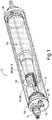
- FIG. 1 is a perspective top view of a pressure-neutral electric motor 01 according to the invention (also “elevator motor”) shown, which can be used up to hadal diving depths. Reference symbols which cannot be clearly recognized in a representation are the Fig. 2 refer to.
- a cylindrical housing 02 can be seen in which a motor unit 03 and a reversibly deformable pressure compensation element 04 for pressure compensation between a pressure fluid 07 and the hydrostatic pressure acting on the motor unit 03 are arranged.
- the cylindrical housing 02 is made of a transparent plastic, for example PMMA or PC.
- the motor unit 03 comprises a direct current motor with carbon brushes, a five-stage planetary gear and a magnetic pulse generator (for example from Faulhaber GmbH TM, brochure " DC micro motors ", accessed on the Internet on August 15, 2017 under URL 5, dimensions: ⁇ 40 mm x 252 mm total length, titanium output shaft ⁇ 8 mm x 16 mm with flat, ⁇ 20 mm x 10 mm centering pin, designation 2342S012C R IE2-16 261 415: 1, 12V DC motor 2342 with five-stage planetary gear 26 / 1 with ratio 415: 1 and magnetic pulse generator IE2 with two channels and 16 pulses per revolution).
- a direct current motor with carbon brushes for example from Faulhaber GmbH TM, brochure " DC micro motors ", accessed on the Internet on August 15, 2017 under URL 5, dimensions: ⁇ 40 mm x 252 mm total length, titanium output shaft ⁇ 8 mm x 16 mm with flat, ⁇ 20 mm x 10 mm centering pin, designation 2342
- the dry weight of the electric motor 01 is 452 g, with liquid filling on land 573 g and in sea water 342 g.
- the cylindrical housing 02 has a first cover 05 at one end and a first cover 05 at its other end closed pressure-tight with a second cover 06 (both preferably made of plastic). For more details see Fig. 2 .
- the cylindrical housing 02 and the motor unit 03 are filled with 75 ml (a larger filling reduces the possibility of temperature compensation) of a dielectric pressure fluid 07 without gas bubbles.
- the hydraulic fluid 07 is a commercially available inert hydrofluoroether 08 (for example brochure "3M TM Novec TM 7500 Engineered Fluid" (high-tech liquid) accessed on the Internet on 08/15/2017 under URL 6 ).
- the pressure compensation element 04 which is loosely wrapped around the motor unit 03 within the cylindrical housing 02, is also inserted into the pressure fluid 07 .
- the pressure equalization element 04 is a closed pressure bag 09 with a supply hose 10 which is open at its end facing away from the pressure bag 09 and which leads out of the cylindrical housing 02 or from the second cover 06 in a pressure-tight manner.
- the pressure bag 09 is a commercially available medical bag 18 made of polyvinyl chloride (PVC), the volume of which can be easily adapted to the volume of the cylindrical housing 02 and the motor unit 03 by cutting it off and again pressure-tight welding.
- the internal pressure bag 09 can expand by around 25 ml to 30 ml (when it becomes very bulky). So that the electric motor 01 claimed by the invention can compensate for pressure and temperature fluctuations, the filling level of the hydraulic fluid 07 must be checked before it is used in the deep sea. 600 bar overpressure and a temperature decrease from 25 ° C to 0 ° C lead to a volume loss of around 8%, so with an assumed target volume of 75 ml, around 6 ml must be compensated.
- FIG. 2 the claimed, pressure-neutral electric motor 01 is shown in the exploded view (housing 02 shown in abbreviated form).
- the output shaft 11 rotates without load at 12 V and approx. 0.6 A at 15 rpm.
- the supply hose 10 of the pressure bag 09 (shown in abbreviated form) is led out pressure-tight through the second cover 06.
- a sealing tube 13 is in its open end (see also Fig. 1 ) and secured with a whipping (cord wrapping on the outside of the supply hose 10 ).
- an electrical connection 14 (Subconn® connector MCBH6MTI (Titan) with pin assignment for MPI bus modular) is led out of the second cover 06 in a pressure-tight manner.
- the electrical connection 14 is electrically connected to a plug 15 of the motor unit 03 .
- the seal of the drive shaft 12 consists of an O-ring which is held between the shoulders of two plastic plain bearings. To remove the O-ring, the bearing on the gearbox side of the motor unit 03 must be pushed out.
- the output shaft 11 is positively bonded to the drive shaft 12 with epoxy resin with an eroded bore and can only be removed by heating above 120.degree. However, this is only necessary for repair work.
- a pressure-tight closable through-hole 16 is located in the second cover 06 (cf. Fig. 1 ), which is used to fill with hydraulic fluid 07 and to vent the motor unit 03 .
- the through hole 16 is provided with a screw plug 17 (cf. Fig. 1 ) sealed pressure-tight after completion of filling and venting.
- the pressure-neutral electric motor 01 For deep-sea suitability with very high hydrostatic pressures, it must be ensured in the claimed, pressure-neutral electric motor 01 that there are no compressible pressure chambers.
- the pressure fluid 07 can be degassed under vacuum. This takes place, for example, in a closed vacuum chamber. Since it is difficult here to lead connection lines out of the vacuum, the electric motor 01 can be filled with hydraulic fluid 07 outside the pressure chamber under atmospheric pressure and then placed in the pressure chamber for degassing and placed under vacuum. This alternating process can also be repeated several times until all gas bubbles have reliably emerged from the electric motor 01 .
- the entire filling process can also take place in a vacuum, it being necessary to ensure that the pressure fluid 07 safely reaches the interior of the electric motor 01.
- the filling is done, for example, with a simple syringe.
- the pressure bag 09 is inflated with air to its normal volume state and closed pressure-tight.
- the filling process is terminated.
- a stand is suitable, in which ⁇ 20 mm holes are drilled for the vertical installation of the electric motor 01 .
- the screw plug 17 next to the electrical connection 14 must be unscrewed.
- the hydraulic fluid 07 can easily be filled in with a simple syringe with a cannula. Care must be taken that the open end of the supply hose 10 is not accidentally filled.
- the pressure bag 09 has its open end of the supply hose 10 is always contact with the environment, so that the pressure bag 09 is always filled with the surrounding medium, and under the pressure it then transmits to the pressure fluid 07th If the electric motor 01 is refilled or if the level of the hydraulic fluid 07 was significantly lower than the upper edge of the encoder of the motor unit 03, it is advisable to vent the motor in a desiccator under vacuum.
- the electric motor 01 is filled with the desired amount of the pressure fluid 07 and placed open in a vacuum chamber.
- the air is then sucked off to below 10 mbar, the pressure fluid 07 beginning to boil strongly.
- the low pressure is held for one minute, after which the vacuum chamber is vented again.
- the level of the hydraulic fluid 07 drops significantly because there are vapor bubbles in the Motor unit 03 collapse.
- negative pressure can be applied again. In this case, however, the pressure should not fall below the vapor pressure of the hydraulic fluid 07 .
- the air is then sucked off to 0.4 bar and the liquid level is observed. If the liquid level rises, there are still air bubbles in the motor unit 03, which is why further venting measures are required. If the fluid level remains constant, venting was successful. There are no more air bubbles in the motor unit 03.
- the cylindrical housing 02 can be closed.
- a syringe filled with 20 ml of air is inserted into the open end of the connection hose 10 of the pressure bag 09 .
- the electric motor 01 is then held at an angle and the air is filled into the pressure bag 09 so that the liquid level rises and all air can escape. It must be checked whether the amount of air pressed in roughly corresponds to the selected level.
- the cylindrical housing 02 or the second cover 06 is closed in a pressure-tight manner with the screw plug 17 and an O-ring, which was previously checked for cracks and smeared with silicone grease.
- By subsequently shaking the pressure-neutral electric motor 01 it can be checked whether there are definitely no more disruptive, because decompressible, air bubbles in the motor unit 03 .
- a small air bubble usually remains in the cylindrical housing 02, but this is not critical.
- a power supply unit with 12 V and at least 1 A and an oscilloscope to display the encoder signal are required.
- the electric motor 01 runs at 12 V idling at approx. 15 rpm, drawing 0.58 A to 0.60 A.
- Completely new engines run in first, whereby the grease in the transmission is washed out by the solvent-like hydraulic fluid 08. If the output shaft 11 is loaded, the electric motor 01 can easily draw 2 A to 3 A.
- the two encoder channels output a phase-shifted square-wave signal when they are supplied with 4 V to 18 V of current.
- the pressure bag 09 is loosely, ie, placed around the motor unit 03 at a certain distance, so that the pressure fluid 07 can also penetrate well between the pressure bag 09 and the motor unit 03 and completely surround the pressure bag 09.
- the deformable pressure bag 09 adapts very well to the cylindrical housing 02 and the motor unit 03 .
- the electric motor 01 is still cooled by the cold sea water in the pressure bag 09. It is particularly space-saving, so that the pressure-neutral electric motor 01 according to the invention can be designed to be particularly compact and light.
- it is relatively inexpensive because it manages with many commercially available components, in particular the simple medical bag 18 as a pressure bag 09.
Landscapes
- Engineering & Computer Science (AREA)
- Power Engineering (AREA)
- Microelectronics & Electronic Packaging (AREA)
- Motor Or Generator Frames (AREA)
- Reciprocating Pumps (AREA)
Description
- Die Erfindung bezieht sich auf einen druckneutralen Elektromotor zum Einsatz in der Tiefsee mit einem Gehäuse, in dem eine mit einer dielektrischen Druckflüssigkeit gefüllte Motoreinheit, wobei das Befüllen unter Atmosphärendruck alternierend mit einer Entlüftung im Vakuum erfolgt, um eine luftblasenfreie Füllung am Ende des Befüllens zu garantieren, und ein reversibel verformbares Druckausgleichselement zum Druckausgleich zwischen der Druckflüssigkeit und dem im Einsatzfall auf die Motoreinheit einwirkenden hydrostatischen Druck angeordnet sind.
- Zur Erforschung der benthischen und pelagialen Gebiete der Tiefsee (90% aller Meere haben eine Tiefe zwischen 1000 m und 5000 m) werden ferngesteuerte oder autonome Messgeräte und Fahrzeuge eingesetzt. Mit deren Hilfe können Daten aller Art über den Boden, die Bewohner und das Wasser der Tiefsee gewonnen werden. Zum Antrieb der agierenden Komponenten werden zumeist Elektromotoren verwendet, die jedoch dem großen hydrostatischen Druck in der Tiefsee standhalten müssen. Zur entsprechenden Ertüchtigung der Elektromotoren werden zwei grundsätzlich verschiedene Konzepte verfolgt. Zum einen werden druckstabile Behälter für die Elektromotoren eingesetzt, die eine große Druckdifferenz zwischen Innenraum und Außenraum zulassen. Zum anderen werden druckneutrale Systeme (DNS, auch drucktolerante Systeme, engl. pressure tolerant systems) eingesetzt, bei denen alle Komponenten gleichmäßig und damit stabilisierend von allen Seiten dem hohen Druck ausgesetzt werden. Druckdifferenzen treten somit nicht auf. Grundvoraussetzung für ein DNS ist, dass die Komponenten auch unter hohen Drücken funktionsfähig sind. Neben Feststoffen werden Druckfluide eingesetzt, die alle ggfs. vorhandenen Lufträume (Drucckammern) in der Komponente ausfüllen. DNS benötigen keine stabilen Druckbehälter und können in allen Tiefen eingesetzt werden. Ebenso entfallen die zu berücksichtigenden vergrößerten Bauraumabmessungen sowie druckdichten Durchführungen und Zugänge in das Innere der Druckbehälter mit komplexen Öffnungs- und Schließprozeduren. Es ergibt sich eine erhebliche Gewichtsreduktion und damit Kosteneinsparung. Zu unterscheiden sind feststoffbasierte DNS (vollständiger Einguss in einen seewasserresistenten Kunststoff) und flüssigkeitsbasierte DNS (vollständiges Ausfüllen aller Druckkammern mit einer Druckflüssigkeit). Bei den flüssigkeitsbasierten DNS muss - da auch die Druckflüssigkeiten bei extrem hohen Drücken kompressibel sind - zur Druckanpassung zwischen dem Innenraum der Komponente und der Tiefseeumgebung ein in seinen Abmessungen veränderbares Druckausgleichselement vorgesehen sein, sodass auf die Komponenten keine enorme Druckdifferenz einwirkt. Bei dem Druckausgleichselement kann es sich um einen verschieblichen Kolben, einen Faltenbalg, eine dehnfähige Membran oder ein verformbares Kissen handeln.
- Aus der
US 3 717 078 A ist für Unterwasseranwendungen das Grundprinzip für ein bezüglich des Drucks ausbalanciertes System zum Schutz von Komponenten, die nicht salzwasserfest sind, bekannt. In einem einfachen, nicht druckfesten Gehäuse befinden sich eine Batterie und ein Motor als nichtsalzwasserfeste Komponente (zur Versorgung einer salzwasserfesten Kamera außerhalb des Gehäuses) in einem Ölbad. Die Komponenten selbst sind druckfest, aber nicht mit Öl gefüllt. Im Gehäuse befindet sich eine Membran, die für einen Druckausgleich zwischen dem Öl und der umgebenden hydrostatischen Wassersäule sorgt. Aus derDE 10 2009 032 364 B4 ist eine Vorrichtung für den Unterwasserbetrieb bekannt, bei der die Druckkammern in ihrem Volumen minimiert und die Einbauten druckneutral ausgebildet sind. Der zugehörigen Doktorarbeit "Aufbau druckneutraler, autonomer Unterwasserfahrzeuge in der Tiefsee" (M. Lück, TU Berlin 2010, im Internet abgerufen am 15.08.2017 unter der URL 1) ist zu entnehmen, dass druckneutrale Ringmotoren (Seite 115 unten) eingesetzt werden. Ein solcher Ringmotor ist beispielsweise aus dem Prospektblatt "Ringthruster" der Fa. Enitech vom Januar 2014 bekannt (im Internet abgerufen am 15.08.2017 unter der URL 2). In der Einleitung der Doktorarbeit (Seite 37, 38) ist weiterhin zu lesen, dass fluidkompensierte DNS einen Kompensator, eine einzelne deformierbare Wand oder einen formlosen Beutel, in dessen Inneren die Komponenten angeordnet sind, als Druckausgleichselement aufweisen können. Formlose Beutel haben den Vorteil, dass sie eine maximale Deformation zulassen und teure Kompensatoren ersetzen. Ein sehr kompakter druckneutraler Elektromotor ist in der Beschreibung "maxon Aquatic Solutions" (im Internet abgerufen am 15.08.2017 unter der URL 3) offenbart. In einem zylindrischen Gehäuse sind parallel nebeneinander eine Motoreinheit und ein Druckausgleichselement in Form einer Membran angeordnet. Ein druckneutraler Elektromotor in vollvergossener Form ist schließlich von der Fa. FMT Floren MarineTechnik GmbH (im Internet abgerufen am 15.08.2017 unter der URL 4) bekannt. - Der der Erfindung nächstliegende Stand der Technik wird in der
US 8 328 539 B2 offenbart. Beschrieben wird ein druckneutraler Elektromotor zum Antrieb einer Pumpe in den Tiefen eines flüssigkeitsgefüllten Bohrlochs. Eine zylindrische Motoreinheit ist in einem zylindrischen Gehäuse angeordnet und von einem dielektrischen Motoröl gasblasenfrei ausgefüllt und umgeben. Unterhalb der Motoreinheit befindet sich in axialer Verlängerung im zylindrischen Gehäuse ein reversibel verformbares Druckausgleichselement zum Druckausgleich zwischen der Druckflüssigkeit und dem auf die Motoreinheit einwirkenden hydrostatischen Druck. Bei dem bekannten druckneutralen Elektromotor handelt es sich um einen Faltenbalg oder um eine Membran. Die im Bohrloch anstehende Flüssigkeit kann über Löeher im zylindrischen Gehäuse in das Innere eindringen und den Faltenbalg oder die Membran auf der einen Seite druckbeaufschlagen. Auf der anderen Seite des Faltenbalgs oder der Membran steht das Motoröl an, über das der wirkende hydrostatische Druck dann auf die Motoreinheit übertragen wird. - Aus der
DE 10 2010 044 639 A1 ist es für einen fluidgekühlten Elektromotor bekannt, diesen mit einem Öl zu füllen und mit einer ölgefüllten Kühlmanschette zu umgeben. Der Motor ist für Unterwasserbetrieb vorgesehen und kann aufgrund der Druckfestigkeit der Komponenten in Tiefen von über 1000 m eingesetzt werden. Mittel für eine Druckneutralisation sind aber nicht vorgesehen. Insbesondere weist die Kühlmanschette keine Verbindung mit dem hydrostatischen Druck auf. - Die
US 5 796 197 A zeigt eine Flüssigkeitspumpe für Unterwasseranwendungen, bei der als Druckausgleichselement ein geschlossener Druckbeutel verwendet wird. Der Druckbeutel weist einen offenen Zuleitungsschlauch auf, der druckdicht aus dem Gehäuse herausgeführt ist, Dabei ist der Druckbeutel aber in einer von der Motoreinheit separierten Kammer unterhalb der Motoreinheit angeordnet. DieWO 2011 / 156 424 A1 zeigt ebenfalls eine Flüssigkeitspumpe für Unterwasseranwendungen, bei der um die Motoreinheit ein Schutzbeutel herumgelegt ist. Dieser soll aber die Motoreinheit vor korrosiven Flüssigkeiten schützen und dient nicht dem Druckausgleich. - Aus der
US 3 526 097 A ist ein kurz unter der Wasseroberfläche einzusetzendes System mit einer ölgefüllten Statorkammer und einer gasgefüllten Rotorkammer bekannt. Am Stator werden konstant Blasen erzeugt, die über eine Blasenfalle, eine Abgasleitung und eine Wasserleitung kontinuierlich in die atmosphärische Umgebung abgelassen werden. Die Statorkammer kommuniziert also mit der atmosphärischen Umgebung, sodass es sich um ein offenes System handelt, bei dem flüssigkeits- und gasgefüllte Räume miteinander verbunden sind. Weiterhin befindet sich raumnehmend ein Faltenbalg unterhalb der Motoreinheit, der auf seiner Außenseite von dem Gas und auf seiner Innenseite von der Druckflüssigkeit beaufschlagt ist. Dessen Funktion besteht im Druckausgleich zwischen der ölgefüllten Statorkammer und einer gas- und wassergefüllten Pufferkammer, sodass unmittelbar ein Druckausgleich erfolgt. Um ein Vermischen von Gas und Wasser in der Pufferkammer bei gleichzeitiger Druckübertragung zu verhindern, ist auf den Wasserspiegel ein Pufferfluid (mit "Kolbenfunktion") aufgebracht. Um das Wasser unter Umgebungsdruck zu setzen, ist es über Rohrleitungen mit dem Umgebungswasser verbunden. - Aus der
US 8 523 540 B2 ist ein ähnliches System zur Förderung ein Prozessfluids bekannt. Wiederum befindet sich der Stator des Elektromotors in einer ersten hermetisch abgeschlossenen Kammer, in der ein erstes Fluid umgewälzt wird (geschlossener Kreislauf). Der Rotor befindet sich in einer zweiten abgeschlossenen Kammer, in der ein zweites Fluid umgewälzt wird (offenes System). Beide Kreisläufe sind voneinander getrennt. Das erste Fluid dient der Statorkühlung. Das zweite Fluid dient der Rotorkühlung und wird über Einlässe mit einem 15 bis 20 bar oberhalb des Umgebungsdruckes liegenden Druck zugeführt. Ein unmittelbarer Druckausgleich zwischen dem ersten und dem zweiten Fluid findet in einer Druckausgleichskammer mit einer Trennmembran zwischen beiden Fluiden statt. - Aus der
US 2 002 916 A ist ein tauchfähiger Motor bekannt, der von einer internen Flüssigkeit umspült wird (geschlossener Kreislauf). Eine Druckübertragungskammer mit einer oberen und einer unteren Sektion ist raumnehmend oberhalb des Motors angeordnet und wird ebenfalls von der Flüssigkeit durchspült. In der oberen Sektion der Druckübertragungskammer befindet sich ein Faltenbalg, der in seinem Inneren von Umgebungswasser ausgefüllt ist und dessen Druck auf die Flüssigkeit überträgt. Der Faltenbalg steht unter einer Vorspannung. Er erzeugt dadurch einen Überdruck, der eine Leckage an einer Wellendurchführung nur nach außen in die atmosphärische Umgebung erzwingen soll. - Aus der
US 2 857 181 A ist eine ähnliche Anordnung mit einem flüssigkeitsumspülten Motor und einem dazu in Reihe geschalteten, vorgespannten Faltenbalg bekannt, wobei über den Faltenbalg der Innendruck des Motorgehäuses (mit Stator und Rotor) kontrolliert werden soll. Über Zu- und Ablaufleitungen steht das Öl im Inneren des Motorgehäuses mit der atmosphärischen Umgebung in Verbindung, sodass es sich wiederum um ein offenes System handelt, das nicht für den Einsatz in der Tiefsee geeignet ist. - Ausgehend von dem zuvor erläuterten nächstliegenden Stand der Technik ist die Aufgabe für die vorliegende Erfindung darin zu sehen, den eingangs beschriebene gattungsgemäßen druckneutralen Elektromotor zum Unterwassereinsatz in der Tiefsee so weiterzubilden, dass eine besonders einfache Ausgestaltung hinsichtlich Konstruktion und Handhabung unter möglichst weitgehendem Einsatz von handelsüblichen Komponenten erreicht wird. Dabei sollen alle Vorteile eines druckneutralen Systems erhalten bleiben. Die Lösung für diese Aufgabe ist dem unabhängigen Anspruch 1 zu entnehmen. Vorteilhafte Weiterbildungen der Erfindung werden in den Unteransprüchen aufgezeigt und im Folgenden im Zusammenhang mit der Erfindung näher erläutert.
- Erfindungsgemäß ist bei dem beanspruchten druckneutralen Elektromotor vorgesehen, dass das reversibel verformbare Druckausgleichselement als geschlossener Druckbeutel mit einem offenen, aus dem Gehäuse druckdicht herausgeführten Zuleitungsschlauch ausgebildet und mit einigem Abstand, sodass die Druckflüssigkeit auch gut zwischen den Druckbeutel und die zylindrische Motoreinheit dringen kann und der Druckbeutel auf seiner Außenseite vollständig von Druckflüssigkeit umgeben ist, um die Motoreinheit innerhalb des Gehäuses herumgelegt ist, wobei der Druckbeutel beim Befüllen mit Luft gefüllt und auf seinen normalen Volumenzustand aufgebläht ist, dass das Gehäuse durchsichtig ausgebildet und dass als Druckflüssigkeit ein kommerziell erhältlicher Hydrofluorether eingesetzt ist. Durch diese Anordnung ergibt sich eine besonders kompakte und kostengünstige Bauweise. Durch die Anordnung des Druckbeutels im Inneren des Gehäuses wird eine Gewichtsreduzierung in Höhe des doppelten Beutelvolumens multipliziert mit der Dichte der Druckflüssigkeit erreicht. Insgesamt wird eine deutliche Verbesserung der Einsatzfähigkeit und Handhabbarkeit beim beanspruchten Elektromotor für den komplexen Unterwassereinsatz erreicht. Dabei wird es in der Praxis bevorzugt sein, dass jedes in der Tiefsee eingesetzte und anzutreibende Gerät seinen eigenen Elektromotor erhält, sodass dieser relativ klein dimensioniert sein kann. Zentralantriebe werden vermieden, beim Ausfall eines Elektroantriebs können durch die anderen dezentralen Elektroantriebe die anderen Geräte noch weiterbetrieben werden. Ein besonderer Vorteil bei dem mit der Erfindung beanspruchten druckneutralen Elektromotor besteht darin, dass keine druckstabilen Gehäuse, die groß, schwer, aufwändig in ihrer Handhabung und teuer sind, eingesetzt werden. Vielmehr zeigt der beanspruchte Elektromotor ein besonders geringes Gewicht und besonders handliche Abmaße.
- Bei der Erfindung wird ein reversibel verformbarer druckdichter Druckbeutel eingesetzt, der im Einsatzfall unter Wasser auf seiner Außenseite von der Druckflüssigkeit umgeben und in seinem Inneren vom Wasser ausgefüllt ist, das den der Tauchtiefe entsprechenden hydrostatischen Druck ausübt. Dieser wird dann über den Druckbeutel auf die Druckflüssigkeit übertragen. Es kommt zu einem Druckausgleich, auf alle Komponenten wird gleichmäßig der gleiche große hydrostatische Druck ausgeübt. Befindet sich der Elektromotor in luftiger Umgebung, ist der Druckbeutel mit Luft gefüllt. Der Druckbeutel kann zwischen der Motoreinheit und dem Gehäuse "atmen". Bei ansteigendem Druck wird der Druckbeutel in seinem Volumen durch den in seinem Inneren zunehmenden Wasserdruck größer und drückt die Druckflüssigkeit zunehmend zusammen. Bei geringer werdendem Druck wird der Druckbeutel in seinem Volumen durch den in seinem Inneren abnehmenden Wasserdruck wieder kleiner und lässt eine Expansion der Druckflüssigkeit zu. Beim Befüllen mit Druckflüssigkeit kann über die eingefüllte Menge eingestellt werden, ob der Druckbeutel zu Beginn des Absenkens des Elektromotors in die vorgesehene Tauchtiefe eher voll oder leer ist. Die optimale Füllmenge hängt vom Einsatzprofil des Elektromotors ab. In großen Tauchtiefen wird die Druckflüssigkeit stark zusammengedrückt (es kann mehr Druckflüssigkeit eingefüllt werden), bei starker Wärmeeinwirkung (beispielsweise bei einer Lagerung der Batterie auf einem sonnenbeschienenen Schiffsdeck) dehnt sich die Druckflüssigkeit aus (es kann weniger Druckflüssigkeit eingefüllt werden). In diesem Falle ist der Beutel dann aber auch in seinem Inneren mit Luft gefüllt und kann weitgehend komprimiert werden. Wasser und Luft dringen über den offenen Zuleitungsschlauch in das Innere des Druckbeutels, wobei der Zuleitungsschlauch ebenfalls von Druckflüssigkeit umgeben und druckdicht aus dem Gehäuse herausgeführt ist. Bei dem beanspruchten druckneutralen Elektromotor wird durch die Verwendung eines geschlossenen Druckbeutels die in der Regel zylindrische Motoreinheit einfach und platzsparend umwickelt. Im Einsatzfall ist der Druckbeutel mit kaltem Tiefseewasser gefüllt, wodurch als zusätzlicher Vorteil die Motoreinheit auch noch besonders einfach gekühlt und damit vor einer Überhitzung geschützt werden kann.
- Die bei der Erfindung eingesetzte Druckflüssigkeit darf die Funktionsfähigkeit des Motors nicht beeinflussen. Bei einer Verwendung von Weißöl (Vaseline) wird dieses unvorteilhafterweise im Bürstenfeuer verbrannt. Bei einem Einsatz von Silikonöl rutschen die Bürsten aufgrund der starken Schmierung durch. Erfindungsgemäß wird deshalb als Druckflüssigkeit ein kommerziell erhältlicher Hydrofluorether eingesetzt. Hierbei handelt es sich um ein inertes Fluid, das die oben erwähnten Nachteile nicht aufweist.
- Um die Motoreinheit und den Druckbeutel einfach in das Gehäuse, das besonders bevorzugt und vorteilhaft zylindrisch ausgeführt ist, einbringen zu können, ist dieses bevorzugt an beiden Enden offen. Es handelt sich damit um ein einfaches Rohr, das als Gehäuse eingesetzt werden kann. Bei Verwendung eines Rohrs als Gehäuse ist es bevorzugt und vorteilhaft, wenn das Gehäuse an seinem einen Ende mit einem ersten Deckel und an seinem anderen Ende mit einem zweiten Deckel druckdicht verschlossen ist. Die Deckel können aus einem Kunststoff, beispielsweise aus Polyoxymethylen POM, bestehen und mit Dichtungsringen in das Gehäuse eingedichtet werden. Jeweils zwei bis vier Schrauben sorgen für einen sicheren Sitz. Bei Verwendung von zwei Deckeln ist es weiterhin bevorzugt und vorteilhaft, wenn durch den ersten Deckel eine mit der Motoreinheit in Verbindung stehende Ausgangswelle und durch den zweiten Deckel der Zuleitungsschlauch des Druckbeutels und ein elektrischer Anschluss für die Motoreinheit druckdicht herausgeführt sind. Die Ausgangswelle kann beispielsweise aus Titan bestehen und an eine Edelstahlwelle der Motoreinheit angedockt werden. Der Zuleitungsschlauch des Druckbeutels wird mit einem Dichtungsrohr druckdicht in den zweiten Deckel eingepasst. Durch das Dichtungsrohr bleibt dabei die Verbindung in das Innere des Druckbeutels für den Druckausgleich mit der Umgebung offen. Desweiteren ist es bei der Erfindung bevorzugt und vorteilhaft, wenn im zweiten Deckel eine druckdicht verschließbare Durchgangsbohrung vorgesehen ist, die der Befüllung mit Druckflüssigkeit und Entlüftung der Motoreinheit dient. Der druckdichte Verschluss im zweiten Deckel kann beispielsweise durch einen Verschlussstopfen mit Elastomerdichtung umgesetzt werden. Vorteilhafterweise erfolgt das Befüllen des Elektromotors ein- oder mehrfach alternierend mit einer Entlüftung im Vakuum (beispielsweise in einer Vakuumkammer), um eine luftblasenfreie Füllung sicher garantieren zu können. Das Befüllen erfolgt unter Atmosphärendruck beispielsweise mit einer einfachen Spritze (ggfs. mit Nadelaufsatz). Beim Befüllen ist der Druckbeutel mit Luft auf seinen normalen Volumenzustand aufgebläht und druckdicht verschlossen. Sobald Drückflüssigkeit aus der Durchgangsbohrung austritt, wird der Füllvorgang abgebrochen.
- Bei dem erfindungsgemäßen druckneutralen Elektromotor ist das Gehäuse kein Druckgehäuse und muss keinen großen Druckdifferenzen standhalten. Insbesondere kann das Gehäuse somit auch aus einem dünnen, leichten und kostengünstigen Kunststoff, insbesondere auch aus einem einfachen Kunststoffrohr, sein. Erfindungsgemäß besteht das Gehäuse aus einem transparenten Material und ist durchsichtig ausgebildet. Damit kann das Innere wie durch ein Schaufenster beispielsweise beim Befüllen mit Druckflüssigkeit gut beobachtete werden. Aufsteigende Gasblasen werden sofort bemerkt und der Füllvorgang noch weiter durchgeführt. Weiterhin ergibt sich eine einfache Montage und Handhabbarkeit des beanspruchten druckneutralen Elektromotors. Insbesondere eignet sich bevorzugt und vorteilhaft der Einsatz von transparentem Polymethylmethacrylat PMMA oder Polycarbonat PC für das transparente Gehäuse. Beide Kunststoffe sind hochtransparent und dauerhaft resistent gegen Salzwasser, wobei PC noch schlagfester ist als PMMA ist.
- Weiterhin kann bei der Erfindung bevorzugt und vorteilhaft als Druckbeutel ein kommerziell erhältlicher Schlauchbeutel mit einem integrierten offenen Zuleitungsschlauch eingesetzt werden, wobei in das Ende des offenen Zuleitungsschlauchs ein Dichtungsrohr eingesetzt ist. Druckdicht festgehalten wird das Dichtungsrohr im Zuleitungsschlauch durch ein Takling (feste Schnurumwicklung) auf dem Zuleitungsschlauch und einen O-Ring. Dabei ist das Dichtungsrohr in seiner Mitte offen, sodass immer eine Verbindung zwischen dem Beutelinneren und der jeweiligen Umgebung hergestellt ist. Der Beutel ist also immer mit dem entsprechenden Medium (Wasser oder Luft) in gefüllt. Derartige medizinische Schlauchbeutel werden im medizinischen Sektor eingesetzt und sind als Infusions-, Urin- oder Sekretbeutel bekannt und in unterschiedlichen Volumengrößen und in der Regel aus Polyvinylchlorid bestehend am Markt erhältlich. Sie weisen immer einen Zuleitungsschlauch auf, der an seinem freien Ende verschließbar ist. Die medizinischen Beutel bestehen aus einem festen, reversibel verformbaren Kunststoff und lassen sich einfach auf das gewünschte Volumen zuschneiden und wieder verschweißen. Eine Verwendung von aluminiumbedampften Mehrschichtbeuteln, wie sie als Getränkebeutel bekannt sind, können ebenfalls eingesetzt werden.
- Schließlich ist es noch vorteilhaft und bevorzugt, wenn die Motoreinheit ein Getriebe und einen Impulsgeber umfasst. Derartige Motoreinheiten sind kommerziell erhältlich und können als "Elevatormotor" bezeichnet werden. Weiter oben wurde bereits erwähnt, dass herkömmliche Druckflüssigkeiten Probleme verursachen können. Vorteilhaft wäre es daher, bürstenlose Elektromotoren einsetzen zu können. Diese verfügen aber über eine Elektronik, die zusätzlich Strom verbraucht. Elektromotoren mit Bürsten benötigen keine Steuerelektronik, benötigen aber eine spezielle Druckflüssigkeit. Optimal ist ein Elektromotor, der in Wasser läuft und ein nichtrostendes Getriebe, also insbesondere aus Kunststoff, aufweist. Weitere Details zur Erfindung und ihren Ausführungsformen sind den nachfolgend beschriebenen Ausführungsbeispielen zu entnehmen.
- Nachfolgend werden der druckneutrale Elektromotor zum Einsatz in der Tiefsee nach der Erfindung und seine vorteilhaften Modifikationen anhand der schematischen Figuren zum besseren Verständnis der Erfindung noch weitergehend erläutert. Dabei zeigt die
- Fig. 1
- den druckneutralen Elektromotor in der perspektivischen Ansicht und
- Fig. 2
- den druckneutralen Elektromotor in der Explosionsdarstellung.
- In der
Fig. 1 ist eine perspektivische Draufsicht auf einen druckneutralen Elektromotor 01 nach der Erfindung (auch "Elevatormotor") gezeigt, der bis zu hadalen Tauchtiefen eingesetzt werden kann. In einer Darstellung nicht ausreichend deutlich zu erkennende Bezugszeichen sind derFig. 2 zu entnehmen. Zu erkennen ist ein zylindrisches Gehäuse 02, in dem eine Motoreinheit 03 und ein reversibel verformbares Druckausgleichselement 04 zum Druckausgleich zwischen einer Druckflüssigkeit 07 und dem auf die Motoreinheit 03 einwirkenden hydrostatischen Druck angeordnet sind. Im gezeigten Ausführungsbeispiel ist das zylindrische Gehäuse 02 aus einem transparenten Kunststoff, beispielsweise PMMA oder PC, ausgeführt. Die Motoreinheit 03 umfasst einen Gleichstrommotor mit Kohlebürsten, ein fünfstufiges Planetengetriebe und einen magnetischen Impulsgeber (beispielsweise von Fa. Faulhaber GmbH™, Prospektblatt "DC-Kleinstmotoren", im Internet abgerufen am 15.08.2017 unter der URL 5, Maße: Ø40 mm x 252 mm Gesamtlänge, Titan Ausgangswelle Ø8 mm x 16 mm mit Abflachung, Ø20 mm x 10 mm Zentrierzapfen, Bezeichnung 2342S012C R IE2-16 261 415:1, 12V DC Motor 2342 mit fünfstufigem Planetengetriebe 26/1 mit Übersetzung 415:1 und magnetischem Impulsgeber IE2 mit zwei Kanälen und 16 Impulsen pro Umdrehung). Das Trockengewicht des Elektromotors 01 beträgt 452 g, mit Flüssigkeitsfüllung an Land 573 g und in Meerwasser 342 g. Das zylindrische Gehäuse 02 ist an seinem einen Ende mit einem ersten Deckel 05 und an seinem anderen Ende mit einem zweiten Deckel 06 (beide bevorzugt aus Kunststoff) druckdicht verschlossen. Weitere Details sieheFig. 2 . - Das zylindrische Gehäuse 02 und die Motoreinheit 03 sind im gezeigten Ausführungsbeispiel mit 75 ml (eine größere Füllung reduziert die Möglichkeit der Temperaturkompensation) einer dielektrischen Druckflüssigkeit 07 gasblasenfrei gefüllt. Im gewählten Ausführungsbeispiel handelt es sich bei der Druckflüssigkeit 07 um einen kommerziell erhältlichen inerten Hydrofluorether 08 (beispielsweise Prospektblatt "3M™ Novec™7500 Engineered Fluid" (High-Tech-Flüssigkeit) im Internet abgerufen am 15.08.2017 unter der URL 6). In die Druckflüssigkeit 07 ist auch das Druckausgleichselement 04 eingelegt, das locker um die Motoreinheit 03 innerhalb des zylindrischen Gehäuses 02 herumgelegt ist. Bei dem Druckausgleichselement 04 handelt es sich um einen geschlossenen Druckbeutel 09 mit einem an seinem vom Druckbeutel 09 abgewandten Ende offenen Zuleitungsschlauch 10, der aus dem zylindrischen Gehäuse 02 bzw. aus dem zweiten Deckel 06 druckdicht herausgeführt ist. Bei dem Druckbeutel 09 handelt es sich im gezeigten Ausführungsbeispiel um einen handelsüblichen medizinischen Beutel 18 aus Polyvinylchlorid (PVC), der durch Abschneiden und erneutes druckdichtes Verschweißen einfach in seinem Volumen an das Volumen des zylindrischen Gehäuses 02 und der Motoreinheit 03 angepasst werden kann. Der interne Druckbeutel 09 kann sich etwa 25 ml bis 30 ml (wenn er ganz prall wird) ausdehnen. Damit der mit der Erfindung beanspruchte Elektromotor 01 Druck- und Temperaturschwankungen kompensieren kann, muss vor dem Einsatz in der Tiefsee der Füllstand der Druckflüssigkeit 07 kontrolliert werden. 600 bar Überdruck und eine Temperaturabnahme von 25°C auf 0°C führen zu etwa 8% Volumenschwund, bei einem angenommenen Sollvolumen von 75 ml müssen also etwa 6 ml kompensiert werden.
- In der
Fig. 2 ist der beanspruchte druckneutrale Elektromotor 01 in der Explosionsdarstellung aufgezeigt (Gehäuse 02 verkürzt dargestellt). Gut zu erkennen ist der erste Deckel 05 mit einer Ausgangswelle 11 (beispielsweise aus Titan), die mit einer Antriebswelle 12 (beispielsweise aus Edelstahl) der Motoreinheit 03 verbunden ist. Die Ausgangswelle 11 dreht bei gefülltem Elektromotor 01 ohne Last bei 12 V und ca. 0,6 A mit 15 U/min. Durch den zweiten Deckel 06 ist der Zuleitungsschlauch 10 des Druckbeutels 09 (verkürzt dargestellt) druckdicht herausgeführt. Dazu ist in sein offenes Ende ein Dichtungsrohr 13 (vergleiche auchFig. 1 ) eingesetzt und mit einem Takling (Schnurumwicklung auf der Außenseite des Zuleitungsschlauchs 10) gesichert. Die Druckdichtheit wird mittels eines O-Rings garantiert. Desweiteren ist ein elektrischer Anschluss 14 (Fa. Subconn® Stecker MCBH6MTI (Titan) mit Pinbelegung für MPI-Bus modular) druckdicht aus dem zweiten Deckel 06 herausgeführt. Auf der Motorseite ist der elektrische Anschluss 14 mit einem Stecker 15 der Motoreinheit 03 elektrisch verbunden. Am ersten Deckel 05 besteht die Dichtung der Antriebswelle 12 aus einem O-Ring, der zwischen den Absätzen von zwei Kunststoff-Gleitlagern gehalten ist. Um den O-Ring auszubauen, muss das getriebeseitige Lager der Motoreinheit 03 herausgedrückt werden. Die Ausgangswelle 11 ist mit einer erodierten Bohrung formschlüssig auf der Antriebswelle 12 mit Epoxidharz aufgeklebt und kann nur mit Erwärmen über 120°C abgenommen werden. Dies ist allerdings nur bei Reparaturarbeiten notwendig. Alle Dichtungen und Gleitlager werden mit Silikonfett geschmiert. Desweiteren befindet sich im zweiten Deckel 06 eine druckdicht verschließbare Durchgangsbohrung 16 (vergleicheFig. 1 ), die der Befüllung mit Druckflüssigkeit 07 und der Entlüftung der Motoreinheit 03 dient. Die Durchgangsbohrung 16 ist mit einer Verschlussschraube 17 (vergleicheFig. 1 ) nach Beendigung von Befüllung und Entlüftung druckdicht verschlossen. - Für die Tiefseeeignung mit sehr großen hydrostatischen Drücken ist bei dem beanspruchten druckneutralen Elektromotor 01 sicherzustellen, dass keine komprimierbaren Druckkammern vorhanden sind. Dazu kann die Druckflüssigkeit 07 unter Vakuum entgast werden. Das erfolgt beispielsweise in einer abgeschlossenen Vakuumkammer. Da es hierbei schwierig ist, Anschlussleitungen aus dem Vakuum herauszuführen, kann der Elektromotor 01 außerhalb der Druckkammer unter Atmosphärendruck mit Druckflüssigkeit 07 befüllt und anschließend zum Entgasen in die Druckkammer gestellt und unter Vakuum gesetzt werden. Dieser alternierende Vorgang kann auch mehrfach wiederholt werden, bis alle Gasblasen zuverlässig aus dem Elektromotor 01 ausgetreten sind. Bei einer Druckkammer mit einer Zuleitungsmöglichkeit kann auch der gesamte Füllvorgang im Vakuum erfolgen, wobei dafür zu sorgen ist, dass die Druckflüssigkeit 07 sicher in das Innere des Elektromotors 01 gelangt. Das Befüllen erfolgt beispielsweise mit einer einfachen Spritze. Beim Befüllen ist der Druckbeutel 09 mit Luft auf seinen normalen Volumenzustand aufgebläht und druckdicht verschlossen. Sobald Drückflüssigkeit 07 aus der Durchgangsbohrung 16 austritt, wird der Füllvorgang abgebrochen. Zum Prüfen des Füllstandes der Druckflüssigkeit 07 im zylindrischen Gehäuse 02 eignet sich ein Ständer, in den Ø20 mm Löcher zum senkrechten Aufstellen des Elektromotors 01 gebohrt sind. Wird die Verschlussschraube 17 herausgeschraubt, strömt Luft in das zylindrische Gehäuse 02 und der Füllstand der Druckflüssigkeit 07 sackt ab. Der korrekte Füllstand kann durch eine Markierung am zylindrischen Gehäuse 02 angezeigt werden. Dabei ist für große Tauchtiefen darauf zu achten, dass die gesamte Motoreinheit 03 in der Druckflüssigkeit 07 liegt.
- Zum Befüllen des Elektromotors 01 muss die Verschlussschraube 17 neben dem elektrischen Anschluss 14 herausgeschraubt werden. Mit einer einfachen Spritze mit Kanüle kann die Druckflüssigkeit 07 leicht eingefüllt werden. Dabei ist darauf zu achten, dass nicht versehentlich das offene Ende des Zuleitungsschlauches 10 gefüllt wird. Der Druckbeutel 09 hat mit seinem offenen Ende des Zuleitungsschlauchs 10 immer Kontakt mit der Umgebung, sodass der Druckbeutel 09 immer mit dem Umgebungsmedium gefüllt ist und unter dessen Druck steht, den er dann an die Druckflüssigkeit 07 überträgt. Wird der Elektromotor 01 neu befüllt oder war der Füllstand der Druckflüssigkeit 07 deutlich tiefer als die obere Kante des Impulsgebers (Encoder) der Motoreinheit 03, empfiehlt es sich, den Motor in einem Exsikkator unter Vakuum zu entlüften. Dazu wird der Elektromotor 01 mit der gewünschten Menge der Druckflüssigkeit 07 gefüllt und offen in eine Vakuumkammer gestellt. Anschließend wird die Luft bis auf unter 10 mbar abgesaugt, wobei die Druckflüssigkeit 07 stark zu kochen beginnt. Der niedrige Druck wird für eine Minute gehalten, danach wird die Vakuumkammer wieder belüftet. Das Niveau der Druckflüssigkeit 07 sinkt deutlich, weil vorhandene Dampfblasen in der Motoreinheit 03 kollabieren. Um die erfolgreiche Entlüftung zu prüfen, kann erneut Unterdruck angelegt werden. Dabei soll der Druck aber nicht unter den Dampfdruck der Druckflüssigkeit 07 fallen. Anschließend wird die Luft bis auf 0,4 bar abgesaugt und der Flüssigkeitsstand beobachtet. Steigt der Flüssigkeitsstand, sind noch Luftblasen in der Motoreinheit 03, weshalb weitere Entlüftungsmaßnahmen erforderlich sind. Bleibt der Flüssigkeitsstand konstant, war die Entlüftung erfolgreich. Es befinden sich keine Luftblasen mehr in der Motoreinheit 03.
- Nachdem der richtige Füllstand eingestellt ist und die Motoreinheit 03 erfolgreich entlüftet wurde, kann das zylindrische Gehäuse 02 geschlossen werden. Dazu wird eine mit 20 ml Luft gefüllte Spritze in das offene Ende des Anschlussschlauches 10 des Druckbeutels 09 eingesteckt. Dann wird der Elektromotor 01 schräg gehalten und die Luft in den Druckbeutel 09 eingefüllt, so dass der Flüssigkeitsstand steigt und alle Luft entweichen kann. Es ist zu überprüfen, ob die hineingedrückte Menge Luft in etwa zu dem gewählten Füllstand passt. Anschließend wird das zylindrische Gehäuse 02 bzw. der zweite Deckel 06 mit der Verschlussschraube 17 und einem O-Ring, der vorher auf Risse geprüft und mit Silikonfett eingeschmiert wurde, druckdicht verschlossen. Durch anschließendes Schütteln des druckneutralen Elektromotors 01 kann überprüft werden, ob sich auch mit Sicherheit keine störenden, weil dekomprimierbaren Luftblasen mehr in der Motoreinheit 03 befinden. Eine kleine Luftblase verbleibt meist im zylindrischen Gehäuse 02, was aber unkritisch ist.
- Für eine Funktionsprüfung des Elektromotors 01 werden ein Netzteil mit 12 V und mindestens 1 A sowie ein Oszilloskop zur Anzeige des Encodersignals benötigt. Der Elektromotor 01 läuft bei 12 V im Leerlauf mit ca. 15 U/Min, wobei er 0,58 A bis 0,60 A zieht. Ganz neue Motoren laufen sich zunächst ein, wobei das Fett im Getriebe von der lösungsmittelähnlichen Druckflüssigkeit 08 herausgewaschen wird. Belastet man die Ausgangswelle 11, kann der Elektromotor 01 leicht 2 A bis 3 A ziehen. Die beiden Encoderkanäle geben ein zueinander phasenverschobenes Rechteck-Signal aus, wenn man sie mit 4 V bis 18 V bestromt.
- Sowohl in
Fig. 1 als auch inFig. 2 ist zu erkennen, wie der Druckbeutel 09 locker, d.h. mit einigem Abstand um die Motoreinheit 03 herumgelegt ist, sodass die Druckflüssigkeit 07 auch gut zwischen den Druckbeutel 09 und die Motoreinheit 03 dringen und den Druckbeutel 09 völlig umgeben kann. Dadurch ist die optimale Druckübertragung zwischen dem hydrostatischen Druck in der Tiefsee im Einsatzfalle des Elektromotors 01 und der Druckflüssigkeit 07 sicher gewährleistet. Der verformbare Druckbeutel 09 passt sich sehr gut dem zylindrischen Gehäuse 02 und der Motoreinheit 03 an. Zusätzlich wird der Elektromotor 01 durch das kalte Seewasser im Druckbeutel 09 noch gekühlt. Er ist besonders platzsparend, sodass der druckneutrale Elektromotor 01 nach der Erfindung besonders kompakt und leicht ausgeführt werden kann. Darüber hinaus ist der relativ kostengünstig, da er mit vielen kommerziell erhältlichen Komponenten, insbesondere dem einfachen medizinischen Beutel 18 als Druckbeutel 09, auskommt. -
- 01
- druckneutraler Elektromotor
- 02
- Gehäuse
- 03
- Motoreinheit
- 04
- Druckausgleichselement
- 05
- erster Deckel
- 06
- zweiter Deckel
- 07
- Druckflüssigkeit
- 08
- Hydrofluorether
- 09
- Druckbeutel
- 10
- Zuleitungsschlauch von 09
- 11
- Ausgangswelle
- 12
- Antriebswelle
- 13
- Dichtungsrohr
- 14
- elektrischer Anschluss
- 15
- Stecker
- 16
- Durchgangsbohrung
- 17
- Verschlussschraube
- 18
- (medizinischer) Schlauchbeutel als 09
- URL 1
https://depositonce.tu-berlin.de/handle/11303/2754 - URL 2
http://www.enitech.de/files/produkte/Datenblatt_Ringthruster.pdf - URL 3
https://www.maxonmotor.de/maxon/view/content/aquatic-solutions - URL 4
http://www.fmt-kempen.de/de/pro/momentall.htm - URL 5
https://fmcc.faulhaber.com/resources/img/DE_2342_CR_DFF.PDF - URL 6
http://multimedia.3m.com/mws/media/65496O/3mtm-novectm-7500-engineered-fluid.pdf?fn=prodinfo_nvc7500.pdf
Claims (8)
- Druckneutraler Elektromotor (01) zum Unterwassereinsatz in der Tiefsee mit einem Gehäuse (02), in dem eine mit einer dielektrischen Druckflüssigkeit (07) gefüllte zylindrische Motoreinheit (03), wobei das Befüllen der Motoreinheit (03) unter Atmosphärendruck alternierend mit einer Entlüftung im Vakuum erfolgt, um eine luftblasenfreie Füllung am Ende des Befüllens der Motoreinheit (03) zu garantieren, und ein reversibel verformbares Druckausgleichselement (04) zum Druckausgleich zwischen der Druckflüssigkeit (07) und dem im Unterwassereinsatz auf die Motoreinheit (03) einwirkenden hydrostatischen Druck angeordnet sind, dadurch gekennzeichnet, dass das reversibel verformbare Druckausgleichselement (04) als druckdichter Druckbeutel (09) mit einem am vom Druckbeutel (09) abgewandten Ende offenen, aus dem Gehäuse (02) druckdicht herausgeführten Zuleitungsschlauch (10) ausgebildet und mit einigem Abstand, sodass die Druckflüssigkeit (07) auch gut zwischen den Druckbeutel (09) und die Motoreinheit (03) dringen kann und der Druckbeutel (09) auf seiner Außenseite vollständig von Druckflüssigkeit (07) umgeben ist, um die Motoreinheit (03) innerhalb des Gehäuses (02) herumgelegt ist wobei der Druckbeutel (09) beim Befüllen der Motoreinheit (03) mit Luft gefüllt und auf seinen normalen Volumenzustand aufgebläht ist, dass das Gehäuse (02) durchsichtig ausgebildet und dass als Druckflüssigkeit (07) ein kommerziell erhältlicher Hydrofluorether (08) eingesetzt ist.
- Druckneutraler Elektromotor (01) nach Anspruch 1, dadurch gekennzeichnet, dass das Gehäuse (02) zylindrisch ausgebildet ist.
- Druckneutraler Elektromotor (01) nach Anspruch 1 oder 2, dadurch gekennzeichnet, dass das Gehäuse (02) an seinem einen Ende mit einem ersten Deckel (05) und an seinem anderen Ende mit einem zweiten Deckel (06) druckdicht verschlossen ist.
- Druckneutraler Elektromotor (01) nach Anspruch 3, dadurch gekennzeichnet, dass durch den ersten Deckel (05) eine mit der Motoreinheit (03) in Verbindung stehende Ausgangswelle (11 und durch den zweiten Deckel (06) der Zuleitungsschlauch (10) des Druckbeutels (09) und ein elektrischer Anschluss (14) für die Motoreinheit (03) druckdicht herausgeführt sind.
- Druckneutraler Elektromotor (01) nach Anspruch 3 oder 4, dadurch gekennzeichnet, dass im zweiten Deckel (06) eine druckdicht verschließbare Durchgangsbohrung (16) vorgesehen ist, die der Befüllung mit Druckflüssigkeit (07) und der Entlüftung der Motoreinheit (03) dient.
- Druckneutraler Elektromotor (01) nach einem der vorangehenden Ansprüche, dadurch gekennzeichnet, dass das Gehäuse (02) aus transparentem Polymethylmethacrylat oder Polycarbonat ausgebildet ist.
- Druckneutraler Elektromotor (01) nach einem der vorangehenden Ansprüche, dadurch gekennzeichnet, dass als Druckbeutel (09) ein kommerziell erhältlicher Schlauchbeutel (18) mit einem integrierten offenen Zuleitungsschlauch (10) eingesetzt ist, wobei in das Ende des offenen Zuleitungsschlauchs (10) ein Dichtungsrohr (13) eingesetzt ist.
- Druckneutraler Elektromotor (01) nach einem der vorangehenden Ansprüche, dadurch gekennzeichnet, dass die Motoreinheit (03) ein Getriebe und einen Impulsgeber umfasst.
Applications Claiming Priority (2)
| Application Number | Priority Date | Filing Date | Title |
|---|---|---|---|
| DE102017119158.5A DE102017119158B3 (de) | 2017-08-22 | 2017-08-22 | Druckneutraler Elektromotor zum Einsatz in der Tiefsee |
| PCT/DE2018/100689 WO2019037813A1 (de) | 2017-08-22 | 2018-08-07 | Druckneutraler elektromotor zum einsatz in der tiefsee |
Publications (2)
| Publication Number | Publication Date |
|---|---|
| EP3673565A1 EP3673565A1 (de) | 2020-07-01 |
| EP3673565B1 true EP3673565B1 (de) | 2021-07-14 |
Family
ID=63404915
Family Applications (1)
| Application Number | Title | Priority Date | Filing Date |
|---|---|---|---|
| EP18759845.3A Active EP3673565B1 (de) | 2017-08-22 | 2018-08-07 | Druckneutraler elektromotor zum einsatz in der tiefsee |
Country Status (4)
| Country | Link |
|---|---|
| EP (1) | EP3673565B1 (de) |
| DE (1) | DE102017119158B3 (de) |
| PT (1) | PT3673565T (de) |
| WO (1) | WO2019037813A1 (de) |
Families Citing this family (2)
| Publication number | Priority date | Publication date | Assignee | Title |
|---|---|---|---|---|
| DE102017130067B4 (de) | 2017-12-15 | 2020-04-16 | Alfred-Wegener-Institut Helmholtz-Zentrum für Polar- und Meeresforschung | Lastkraftunabhängige Auslöseeinrichtung |
| DE102023118565A1 (de) * | 2023-07-13 | 2025-01-16 | Valeo Eautomotive Germany Gmbh | Getriebemotor mit verbesserter Befestigung eines Statorgehäuses |
Family Cites Families (12)
| Publication number | Priority date | Publication date | Assignee | Title |
|---|---|---|---|---|
| US2002916A (en) * | 1934-04-16 | 1935-05-28 | Menborn Inc | Submersible motor construction |
| US2857181A (en) * | 1953-01-19 | 1958-10-21 | Us Electrical Motors Inc | Submersible apparatus |
| US3526097A (en) * | 1966-08-04 | 1970-09-01 | Arthur J Nelson | Submergible apparatus |
| JPS5126720B1 (de) | 1970-04-03 | 1976-08-07 | ||
| US5796197A (en) | 1996-12-09 | 1998-08-18 | Franklin Electric Co., Inc. | Submersible motor sealing system |
| US6795110B1 (en) * | 1999-06-15 | 2004-09-21 | Philip Kossin | Weatherproof and watertight digital electronic camera, including a solid or fluid-filled digital camera operating at great depths |
| WO2007100788A2 (en) * | 2006-02-28 | 2007-09-07 | Vondracek David J | Method and apparatus for a submersible electronic device |
| NO330192B1 (no) * | 2007-04-12 | 2011-03-07 | Framo Eng As | Fluidpumpesystem. |
| DE102009032364B4 (de) | 2008-09-16 | 2012-07-26 | Technische Universität Berlin | Vorrichtung für den Unterwasserbetrieb |
| WO2010078326A1 (en) | 2008-12-30 | 2010-07-08 | Schlumberger Canada Limited | Submersible pump motor protector |
| WO2011156424A1 (en) | 2010-06-07 | 2011-12-15 | Ge Oil & Gas Esp, Inc. | Pfa motor protection bag |
| DE102010044639A1 (de) | 2010-09-07 | 2012-03-08 | Innovative Fertigungstechnologie Gmbh (Ift) | Kühlung eines Elektromotors für den Unterwasserbetrieb |
-
2017
- 2017-08-22 DE DE102017119158.5A patent/DE102017119158B3/de not_active Expired - Fee Related
-
2018
- 2018-08-07 EP EP18759845.3A patent/EP3673565B1/de active Active
- 2018-08-07 WO PCT/DE2018/100689 patent/WO2019037813A1/de not_active Ceased
- 2018-08-07 PT PT187598453T patent/PT3673565T/pt unknown
Non-Patent Citations (1)
| Title |
|---|
| None * |
Also Published As
| Publication number | Publication date |
|---|---|
| DE102017119158B3 (de) | 2018-10-31 |
| EP3673565A1 (de) | 2020-07-01 |
| PT3673565T (pt) | 2021-09-13 |
| WO2019037813A1 (de) | 2019-02-28 |
Similar Documents
| Publication | Publication Date | Title |
|---|---|---|
| DE10261079B4 (de) | Tauchpumpvorrichtung, magnetische Kopplung hierfür und Verfahren zum Pumpen | |
| DE102009032364B4 (de) | Vorrichtung für den Unterwasserbetrieb | |
| EP1441431B1 (de) | Motorgehäuse für einen Elektromotor | |
| DE8118433U1 (de) | Vorrichtung zur steuerung des drucks an wellendichtungsteilen eines geraets | |
| DE102016117910B4 (de) | Pumpensystem mit einer Exzenterschneckenpumpe | |
| DE102017119158B3 (de) | Druckneutraler Elektromotor zum Einsatz in der Tiefsee | |
| DE102015114030A1 (de) | Trommelmotor und Sensorkartusche für einen Trommelmotor | |
| DE102017219084A1 (de) | Elektrohydraulisches System mit einer hydraulischen Achse und mindestens einem geschlossenen Hydraulikkreislauf | |
| DE102017119115B4 (de) | Druckneutrale Batterie zum Einsatz in der Tiefsee | |
| WO2014131563A1 (de) | Bohrloch-fördervorrichtung | |
| DE102018122300A1 (de) | Pumpenaggregat zur Bereitstellung eines Hydraulikdrucks zur Betätigung eines Aktors im Antriebsstrang eines Kraftfahrzeugs | |
| DE102013209682B4 (de) | Gehäuse für ein propellerantriebsaggregat | |
| NO327557B1 (no) | Beskyttelsessystem for pumper | |
| AT505502B1 (de) | Entschwefelungseinrichtung und -verfahren | |
| DE102018217369A1 (de) | Druckkompensationseinrichtung, eingerichtet für Anwendungen unter Wasser | |
| DE2739684A1 (de) | Vorrichtung bei einer eintauchbaren hydraulisch angetriebenen und mit lotrechter achse rotierenden pumpe | |
| DE202015104485U1 (de) | Trommelmotor und Sensorkartusche für einen Trommelmotor | |
| DE1653752B2 (de) | ||
| DE202022107106U1 (de) | Wasserdichtes Verbrauchsmaterial | |
| DE202006010970U1 (de) | Vorrichtung zur Entnahme von Fluidproben | |
| WO2015149767A1 (de) | Betätigungsaktuator | |
| DE102020201630A1 (de) | Tauchvorrichtung für Unterwasserfahrzeuge | |
| DE102005003476A1 (de) | Spaltrohrmotor mit geschlossenem Kühlsystem | |
| EP4610494B1 (de) | Kompressoranordnung zum verdichten eines gases | |
| DE19615171C1 (de) | Pumpe zur Entnahme von Flüssigkeitsproben |
Legal Events
| Date | Code | Title | Description |
|---|---|---|---|
| STAA | Information on the status of an ep patent application or granted ep patent |
Free format text: STATUS: UNKNOWN |
|
| STAA | Information on the status of an ep patent application or granted ep patent |
Free format text: STATUS: THE INTERNATIONAL PUBLICATION HAS BEEN MADE |
|
| PUAI | Public reference made under article 153(3) epc to a published international application that has entered the european phase |
Free format text: ORIGINAL CODE: 0009012 |
|
| STAA | Information on the status of an ep patent application or granted ep patent |
Free format text: STATUS: REQUEST FOR EXAMINATION WAS MADE |
|
| STAA | Information on the status of an ep patent application or granted ep patent |
Free format text: STATUS: EXAMINATION IS IN PROGRESS |
|
| 17P | Request for examination filed |
Effective date: 20200123 |
|
| AK | Designated contracting states |
Kind code of ref document: A1 Designated state(s): AL AT BE BG CH CY CZ DE DK EE ES FI FR GB GR HR HU IE IS IT LI LT LU LV MC MK MT NL NO PL PT RO RS SE SI SK SM TR |
|
| AX | Request for extension of the european patent |
Extension state: BA ME |
|
| 17Q | First examination report despatched |
Effective date: 20200629 |
|
| DAV | Request for validation of the european patent (deleted) | ||
| DAX | Request for extension of the european patent (deleted) | ||
| GRAP | Despatch of communication of intention to grant a patent |
Free format text: ORIGINAL CODE: EPIDOSNIGR1 |
|
| STAA | Information on the status of an ep patent application or granted ep patent |
Free format text: STATUS: GRANT OF PATENT IS INTENDED |
|
| GRAS | Grant fee paid |
Free format text: ORIGINAL CODE: EPIDOSNIGR3 |
|
| GRAA | (expected) grant |
Free format text: ORIGINAL CODE: 0009210 |
|
| STAA | Information on the status of an ep patent application or granted ep patent |
Free format text: STATUS: THE PATENT HAS BEEN GRANTED |
|
| INTG | Intention to grant announced |
Effective date: 20210519 |
|
| AK | Designated contracting states |
Kind code of ref document: B1 Designated state(s): AL AT BE BG CH CY CZ DE DK EE ES FI FR GB GR HR HU IE IS IT LI LT LU LV MC MK MT NL NO PL PT RO RS SE SI SK SM TR |
|
| REG | Reference to a national code |
Ref country code: GB Ref legal event code: FG4D Free format text: NOT ENGLISH |
|
| REG | Reference to a national code |
Ref country code: IE Ref legal event code: FG4D Free format text: LANGUAGE OF EP DOCUMENT: GERMAN |
|
| REG | Reference to a national code |
Ref country code: DE Ref legal event code: R096 Ref document number: 502018006150 Country of ref document: DE |
|
| REG | Reference to a national code |
Ref country code: AT Ref legal event code: REF Ref document number: 1411420 Country of ref document: AT Kind code of ref document: T Effective date: 20210815 |
|
| REG | Reference to a national code |
Ref country code: PT Ref legal event code: SC4A Ref document number: 3673565 Country of ref document: PT Date of ref document: 20210913 Kind code of ref document: T Free format text: AVAILABILITY OF NATIONAL TRANSLATION Effective date: 20210907 |
|
| PGFP | Annual fee paid to national office [announced via postgrant information from national office to epo] |
Ref country code: FR Payment date: 20210802 Year of fee payment: 4 |
|
| REG | Reference to a national code |
Ref country code: LT Ref legal event code: MG9D |
|
| REG | Reference to a national code |
Ref country code: NO Ref legal event code: T2 Effective date: 20210714 |
|
| PGFP | Annual fee paid to national office [announced via postgrant information from national office to epo] |
Ref country code: DE Payment date: 20210803 Year of fee payment: 4 |
|
| PG25 | Lapsed in a contracting state [announced via postgrant information from national office to epo] |
Ref country code: HR Free format text: LAPSE BECAUSE OF FAILURE TO SUBMIT A TRANSLATION OF THE DESCRIPTION OR TO PAY THE FEE WITHIN THE PRESCRIBED TIME-LIMIT Effective date: 20210714 Ref country code: ES Free format text: LAPSE BECAUSE OF FAILURE TO SUBMIT A TRANSLATION OF THE DESCRIPTION OR TO PAY THE FEE WITHIN THE PRESCRIBED TIME-LIMIT Effective date: 20210714 Ref country code: FI Free format text: LAPSE BECAUSE OF FAILURE TO SUBMIT A TRANSLATION OF THE DESCRIPTION OR TO PAY THE FEE WITHIN THE PRESCRIBED TIME-LIMIT Effective date: 20210714 Ref country code: RS Free format text: LAPSE BECAUSE OF FAILURE TO SUBMIT A TRANSLATION OF THE DESCRIPTION OR TO PAY THE FEE WITHIN THE PRESCRIBED TIME-LIMIT Effective date: 20210714 Ref country code: SE Free format text: LAPSE BECAUSE OF FAILURE TO SUBMIT A TRANSLATION OF THE DESCRIPTION OR TO PAY THE FEE WITHIN THE PRESCRIBED TIME-LIMIT Effective date: 20210714 Ref country code: LT Free format text: LAPSE BECAUSE OF FAILURE TO SUBMIT A TRANSLATION OF THE DESCRIPTION OR TO PAY THE FEE WITHIN THE PRESCRIBED TIME-LIMIT Effective date: 20210714 Ref country code: BG Free format text: LAPSE BECAUSE OF FAILURE TO SUBMIT A TRANSLATION OF THE DESCRIPTION OR TO PAY THE FEE WITHIN THE PRESCRIBED TIME-LIMIT Effective date: 20211014 Ref country code: NL Free format text: LAPSE BECAUSE OF FAILURE TO SUBMIT A TRANSLATION OF THE DESCRIPTION OR TO PAY THE FEE WITHIN THE PRESCRIBED TIME-LIMIT Effective date: 20210714 |
|
| PGFP | Annual fee paid to national office [announced via postgrant information from national office to epo] |
Ref country code: NO Payment date: 20210909 Year of fee payment: 4 |
|
| PG25 | Lapsed in a contracting state [announced via postgrant information from national office to epo] |
Ref country code: PL Free format text: LAPSE BECAUSE OF FAILURE TO SUBMIT A TRANSLATION OF THE DESCRIPTION OR TO PAY THE FEE WITHIN THE PRESCRIBED TIME-LIMIT Effective date: 20210714 Ref country code: LV Free format text: LAPSE BECAUSE OF FAILURE TO SUBMIT A TRANSLATION OF THE DESCRIPTION OR TO PAY THE FEE WITHIN THE PRESCRIBED TIME-LIMIT Effective date: 20210714 Ref country code: GR Free format text: LAPSE BECAUSE OF FAILURE TO SUBMIT A TRANSLATION OF THE DESCRIPTION OR TO PAY THE FEE WITHIN THE PRESCRIBED TIME-LIMIT Effective date: 20211015 |
|
| REG | Reference to a national code |
Ref country code: CH Ref legal event code: PL |
|
| REG | Reference to a national code |
Ref country code: DE Ref legal event code: R097 Ref document number: 502018006150 Country of ref document: DE |
|
| REG | Reference to a national code |
Ref country code: BE Ref legal event code: MM Effective date: 20210831 |
|
| PG25 | Lapsed in a contracting state [announced via postgrant information from national office to epo] |
Ref country code: LI Free format text: LAPSE BECAUSE OF NON-PAYMENT OF DUE FEES Effective date: 20210831 Ref country code: DK Free format text: LAPSE BECAUSE OF FAILURE TO SUBMIT A TRANSLATION OF THE DESCRIPTION OR TO PAY THE FEE WITHIN THE PRESCRIBED TIME-LIMIT Effective date: 20210714 Ref country code: CH Free format text: LAPSE BECAUSE OF NON-PAYMENT OF DUE FEES Effective date: 20210831 |
|
| PLBE | No opposition filed within time limit |
Free format text: ORIGINAL CODE: 0009261 |
|
| STAA | Information on the status of an ep patent application or granted ep patent |
Free format text: STATUS: NO OPPOSITION FILED WITHIN TIME LIMIT |
|
| PG25 | Lapsed in a contracting state [announced via postgrant information from national office to epo] |
Ref country code: SM Free format text: LAPSE BECAUSE OF FAILURE TO SUBMIT A TRANSLATION OF THE DESCRIPTION OR TO PAY THE FEE WITHIN THE PRESCRIBED TIME-LIMIT Effective date: 20210714 Ref country code: SK Free format text: LAPSE BECAUSE OF FAILURE TO SUBMIT A TRANSLATION OF THE DESCRIPTION OR TO PAY THE FEE WITHIN THE PRESCRIBED TIME-LIMIT Effective date: 20210714 Ref country code: RO Free format text: LAPSE BECAUSE OF FAILURE TO SUBMIT A TRANSLATION OF THE DESCRIPTION OR TO PAY THE FEE WITHIN THE PRESCRIBED TIME-LIMIT Effective date: 20210714 Ref country code: MC Free format text: LAPSE BECAUSE OF FAILURE TO SUBMIT A TRANSLATION OF THE DESCRIPTION OR TO PAY THE FEE WITHIN THE PRESCRIBED TIME-LIMIT Effective date: 20210714 Ref country code: LU Free format text: LAPSE BECAUSE OF NON-PAYMENT OF DUE FEES Effective date: 20210807 Ref country code: EE Free format text: LAPSE BECAUSE OF FAILURE TO SUBMIT A TRANSLATION OF THE DESCRIPTION OR TO PAY THE FEE WITHIN THE PRESCRIBED TIME-LIMIT Effective date: 20210714 Ref country code: CZ Free format text: LAPSE BECAUSE OF FAILURE TO SUBMIT A TRANSLATION OF THE DESCRIPTION OR TO PAY THE FEE WITHIN THE PRESCRIBED TIME-LIMIT Effective date: 20210714 Ref country code: AL Free format text: LAPSE BECAUSE OF FAILURE TO SUBMIT A TRANSLATION OF THE DESCRIPTION OR TO PAY THE FEE WITHIN THE PRESCRIBED TIME-LIMIT Effective date: 20210714 |
|
| 26N | No opposition filed |
Effective date: 20220419 |
|
| PG25 | Lapsed in a contracting state [announced via postgrant information from national office to epo] |
Ref country code: IT Free format text: LAPSE BECAUSE OF FAILURE TO SUBMIT A TRANSLATION OF THE DESCRIPTION OR TO PAY THE FEE WITHIN THE PRESCRIBED TIME-LIMIT Effective date: 20210714 Ref country code: IE Free format text: LAPSE BECAUSE OF NON-PAYMENT OF DUE FEES Effective date: 20210807 Ref country code: BE Free format text: LAPSE BECAUSE OF NON-PAYMENT OF DUE FEES Effective date: 20210831 |
|
| REG | Reference to a national code |
Ref country code: DE Ref legal event code: R119 Ref document number: 502018006150 Country of ref document: DE |
|
| REG | Reference to a national code |
Ref country code: NO Ref legal event code: MMEP |
|
| GBPC | Gb: european patent ceased through non-payment of renewal fee |
Effective date: 20220807 |
|
| PG25 | Lapsed in a contracting state [announced via postgrant information from national office to epo] |
Ref country code: NO Free format text: LAPSE BECAUSE OF NON-PAYMENT OF DUE FEES Effective date: 20220831 |
|
| PG25 | Lapsed in a contracting state [announced via postgrant information from national office to epo] |
Ref country code: CY Free format text: LAPSE BECAUSE OF FAILURE TO SUBMIT A TRANSLATION OF THE DESCRIPTION OR TO PAY THE FEE WITHIN THE PRESCRIBED TIME-LIMIT Effective date: 20210714 |
|
| PG25 | Lapsed in a contracting state [announced via postgrant information from national office to epo] |
Ref country code: PT Free format text: LAPSE BECAUSE OF NON-PAYMENT OF DUE FEES Effective date: 20230508 Ref country code: HU Free format text: LAPSE BECAUSE OF FAILURE TO SUBMIT A TRANSLATION OF THE DESCRIPTION OR TO PAY THE FEE WITHIN THE PRESCRIBED TIME-LIMIT; INVALID AB INITIO Effective date: 20180807 Ref country code: FR Free format text: LAPSE BECAUSE OF NON-PAYMENT OF DUE FEES Effective date: 20220831 Ref country code: DE Free format text: LAPSE BECAUSE OF NON-PAYMENT OF DUE FEES Effective date: 20230301 |
|
| PG25 | Lapsed in a contracting state [announced via postgrant information from national office to epo] |
Ref country code: GB Free format text: LAPSE BECAUSE OF NON-PAYMENT OF DUE FEES Effective date: 20220807 |
|
| PG25 | Lapsed in a contracting state [announced via postgrant information from national office to epo] |
Ref country code: MK Free format text: LAPSE BECAUSE OF FAILURE TO SUBMIT A TRANSLATION OF THE DESCRIPTION OR TO PAY THE FEE WITHIN THE PRESCRIBED TIME-LIMIT Effective date: 20210714 |
|
| PG25 | Lapsed in a contracting state [announced via postgrant information from national office to epo] |
Ref country code: MT Free format text: LAPSE BECAUSE OF FAILURE TO SUBMIT A TRANSLATION OF THE DESCRIPTION OR TO PAY THE FEE WITHIN THE PRESCRIBED TIME-LIMIT Effective date: 20210714 |
|
| REG | Reference to a national code |
Ref country code: AT Ref legal event code: MM01 Ref document number: 1411420 Country of ref document: AT Kind code of ref document: T Effective date: 20230807 |
|
| PG25 | Lapsed in a contracting state [announced via postgrant information from national office to epo] |
Ref country code: AT Free format text: LAPSE BECAUSE OF NON-PAYMENT OF DUE FEES Effective date: 20230807 |
|
| PG25 | Lapsed in a contracting state [announced via postgrant information from national office to epo] |
Ref country code: AT Free format text: LAPSE BECAUSE OF NON-PAYMENT OF DUE FEES Effective date: 20230807 |
|
| PG25 | Lapsed in a contracting state [announced via postgrant information from national office to epo] |
Ref country code: TR Free format text: LAPSE BECAUSE OF FAILURE TO SUBMIT A TRANSLATION OF THE DESCRIPTION OR TO PAY THE FEE WITHIN THE PRESCRIBED TIME-LIMIT Effective date: 20210714 |
|
| PGFP | Annual fee paid to national office [announced via postgrant information from national office to epo] |
Ref country code: AT Payment date: 20260410 Year of fee payment: 5 |