EP3673497B1 - Abtrennvorrichtung für einen überspannungsableiter - Google Patents
Abtrennvorrichtung für einen überspannungsableiter Download PDFInfo
- Publication number
- EP3673497B1 EP3673497B1 EP19725355.2A EP19725355A EP3673497B1 EP 3673497 B1 EP3673497 B1 EP 3673497B1 EP 19725355 A EP19725355 A EP 19725355A EP 3673497 B1 EP3673497 B1 EP 3673497B1
- Authority
- EP
- European Patent Office
- Prior art keywords
- disconnection
- surge arrester
- point
- support body
- bracket
- Prior art date
- Legal status (The legal status is an assumption and is not a legal conclusion. Google has not performed a legal analysis and makes no representation as to the accuracy of the status listed.)
- Active
Links
- 230000036316 preload Effects 0.000 claims description 4
- 230000000295 complement effect Effects 0.000 claims description 3
- 238000002844 melting Methods 0.000 claims description 3
- 230000008018 melting Effects 0.000 claims description 3
- 238000007689 inspection Methods 0.000 claims 1
- 238000000926 separation method Methods 0.000 description 29
- 229910000679 solder Inorganic materials 0.000 description 5
- 239000004020 conductor Substances 0.000 description 4
- 238000005476 soldering Methods 0.000 description 4
- 230000005540 biological transmission Effects 0.000 description 2
- 230000015572 biosynthetic process Effects 0.000 description 2
- 230000000903 blocking effect Effects 0.000 description 2
- 238000006073 displacement reaction Methods 0.000 description 2
- 238000004519 manufacturing process Methods 0.000 description 2
- 239000000463 material Substances 0.000 description 2
- 238000000034 method Methods 0.000 description 2
- 230000003321 amplification Effects 0.000 description 1
- 238000005452 bending Methods 0.000 description 1
- 238000011161 development Methods 0.000 description 1
- 230000018109 developmental process Effects 0.000 description 1
- 238000010891 electric arc Methods 0.000 description 1
- 230000013011 mating Effects 0.000 description 1
- 238000010309 melting process Methods 0.000 description 1
- 239000002991 molded plastic Substances 0.000 description 1
- 230000007935 neutral effect Effects 0.000 description 1
- 238000003199 nucleic acid amplification method Methods 0.000 description 1
- 230000035515 penetration Effects 0.000 description 1
- 239000004033 plastic Substances 0.000 description 1
- 230000001681 protective effect Effects 0.000 description 1
- 230000000284 resting effect Effects 0.000 description 1
- 230000003685 thermal hair damage Effects 0.000 description 1
- 230000008646 thermal stress Effects 0.000 description 1
- 230000001960 triggered effect Effects 0.000 description 1
Images
Classifications
-
- H—ELECTRICITY
- H01—ELECTRIC ELEMENTS
- H01C—RESISTORS
- H01C7/00—Non-adjustable resistors formed as one or more layers or coatings; Non-adjustable resistors made from powdered conducting material or powdered semi-conducting material with or without insulating material
- H01C7/10—Non-adjustable resistors formed as one or more layers or coatings; Non-adjustable resistors made from powdered conducting material or powdered semi-conducting material with or without insulating material voltage responsive, i.e. varistors
- H01C7/12—Overvoltage protection resistors
- H01C7/126—Means for protecting against excessive pressure or for disconnecting in case of failure
-
- H—ELECTRICITY
- H01—ELECTRIC ELEMENTS
- H01H—ELECTRIC SWITCHES; RELAYS; SELECTORS; EMERGENCY PROTECTIVE DEVICES
- H01H71/00—Details of the protective switches or relays covered by groups H01H73/00 - H01H83/00
- H01H71/08—Terminals; Connections
-
- H—ELECTRICITY
- H01—ELECTRIC ELEMENTS
- H01H—ELECTRIC SWITCHES; RELAYS; SELECTORS; EMERGENCY PROTECTIVE DEVICES
- H01H37/00—Thermally-actuated switches
- H01H37/74—Switches in which only the opening movement or only the closing movement of a contact is effected by heating or cooling
- H01H37/76—Contact member actuated by melting of fusible material, actuated due to burning of combustible material or due to explosion of explosive material
- H01H37/761—Contact member actuated by melting of fusible material, actuated due to burning of combustible material or due to explosion of explosive material with a fusible element forming part of the switched circuit
-
- H—ELECTRICITY
- H01—ELECTRIC ELEMENTS
- H01H—ELECTRIC SWITCHES; RELAYS; SELECTORS; EMERGENCY PROTECTIVE DEVICES
- H01H71/00—Details of the protective switches or relays covered by groups H01H73/00 - H01H83/00
- H01H71/02—Housings; Casings; Bases; Mountings
-
- H—ELECTRICITY
- H01—ELECTRIC ELEMENTS
- H01H—ELECTRIC SWITCHES; RELAYS; SELECTORS; EMERGENCY PROTECTIVE DEVICES
- H01H71/00—Details of the protective switches or relays covered by groups H01H73/00 - H01H83/00
- H01H71/10—Operating or release mechanisms
-
- H—ELECTRICITY
- H01—ELECTRIC ELEMENTS
- H01H—ELECTRIC SWITCHES; RELAYS; SELECTORS; EMERGENCY PROTECTIVE DEVICES
- H01H9/00—Details of switching devices, not covered by groups H01H1/00 - H01H7/00
- H01H9/02—Bases, casings, or covers
- H01H2009/0292—Transparent window or opening, e.g. for allowing visual inspection of contact position or contact condition
-
- H—ELECTRICITY
- H01—ELECTRIC ELEMENTS
- H01H—ELECTRIC SWITCHES; RELAYS; SELECTORS; EMERGENCY PROTECTIVE DEVICES
- H01H37/00—Thermally-actuated switches
- H01H37/74—Switches in which only the opening movement or only the closing movement of a contact is effected by heating or cooling
- H01H37/76—Contact member actuated by melting of fusible material, actuated due to burning of combustible material or due to explosion of explosive material
- H01H37/761—Contact member actuated by melting of fusible material, actuated due to burning of combustible material or due to explosion of explosive material with a fusible element forming part of the switched circuit
- H01H2037/762—Contact member actuated by melting of fusible material, actuated due to burning of combustible material or due to explosion of explosive material with a fusible element forming part of the switched circuit using a spring for opening the circuit when the fusible element melts
- H01H2037/763—Contact member actuated by melting of fusible material, actuated due to burning of combustible material or due to explosion of explosive material with a fusible element forming part of the switched circuit using a spring for opening the circuit when the fusible element melts the spring being a blade spring
-
- H—ELECTRICITY
- H01—ELECTRIC ELEMENTS
- H01T—SPARK GAPS; OVERVOLTAGE ARRESTERS USING SPARK GAPS; SPARKING PLUGS; CORONA DEVICES; GENERATING IONS TO BE INTRODUCED INTO NON-ENCLOSED GASES
- H01T1/00—Details of spark gaps
- H01T1/14—Means structurally associated with spark gap for protecting it against overload or for disconnecting it in case of failure
Definitions
- the invention relates to a surge arrester with a disconnecting device.
- a disconnection device for a surge arrester is previously known.
- the switching movement is carried out by a switching tongue, which is aligned via a permanently acting spring force in the opposite direction to the holding force produced by a protective solder.
- the permanent pre-tensioning force acting indirectly on the switching tongue or its soldering point to generate a desoldering or switching force via a separating block is supported by at least one further, independently acting pre-tensioning force and a supplementary switching force with the same effective direction.
- the distribution of forces is such that in the resting state a small resultant force acts on the soldering point and the greatest possible resultant force executes the switching movement during the desoldering process by creating the pretensioning force in the desoldering phase through the formation of the switching tongue from a memory or bimetallic strip or a Switching tongue made of a spring material, which has an expression with overbend web, provided and the supplementary switching force is formed after the end of the soldering process by shifting a force transmission point of the resulting pretensioning lever force on the switching tongue.
- the displacement of the force transmission point is derived from a rotary movement and in this respect the separating block has a pivot bearing.
- the switching movement of the previously known switching tongue results from a spring tension which, indirectly via the separating block, exerts a pretension on the switching tongue and thus the solder contact point.
- the disconnected switching tongue executes a rapid switching movement over a large opening path and thus creates a reliable separation between the arrester element and the line routing formed by the switching tongue.
- the rotary movement carried out by the separating block is displayed at its end position in a viewing window, so that the switching position of the separating block can be recognized as the triggered state on the outside by means of a viewing surface.
- soldering point that connects the switch tongue to the diverter element is designed and manufactured in such a way that the separation takes place safely and at a point in time at which no thermal damage is to be expected from an overheated diverter element. This point is initially determined by the choice of the perpendicular, with the mechanical pretensioning also providing an essential part of this.
- overvoltage protection element DE 20 2014 103 262 U1 which is intended for use between a neutral conductor and a potential equalization in the power supply of a low-voltage network, the same has a housing and an overvoltage-limiting component arranged in the housing with two connection contacts for the electrical connection of a current path to be protected.
- an electrically conductive connecting element as well as an insulating separating element and at least one spring element.
- a gas-filled surge arrester is used as the surge-limiting component, the insulating separating element being arranged displaceably on the housing and being able to be moved from a first position to a second position by the force of the at least one spring element.
- the second end of an electrically conductive connecting element is electrically conductively connected to the second electrode of the surge arrester via a thermally separating connection and the insulating separating element is fixed in a first position.
- the thermal connection between the second end of the electrically conductive connection element and the second electrode of the surge arrester is broken and the insulating separating element is moved into its second position by the force of the spring element, in which a section of the separating element is located between the second end of the electrically conductive connecting element and the second electrode of the overvoltage element.
- the electrically conductive connecting element is designed as an angled metallic strip and therefore basically has a high current carrying capacity.
- the aforementioned angled portion is present, which forms a contact surface that can be connected to the connection contact.
- a current constriction is formed in the kink area.
- Another disadvantage is the straight-line displacement of the insulating separating element with the risk of tilting in the slide guide provided, in particular when the surge arrester has already been subjected to thermal stress.
- a disconnection device for an overvoltage conductor in which an angled metallic strip is connected with one end to a conductor element via a thermal separation point, and a non-electrically conductive separation element is additionally provided.
- the separating element can be moved from a first to a second position by means of a spring, the movement being prevented by a blocking element connected to the metallic strip. If an overvoltage occurs, which leads to the loosening of the thermal separation point, the metallic strip becomes detached from the diverter element, so that the blocking element no longer prevents the separation element from moving. In the second position the separating element isolates the end of the metallic strip from the diverter element.
- the surge arrester with a disconnecting device which is received by a support body, and with plug contacts extending from the support body to the external connection, which are connected to at least one arrester element of the surge arrester, has a switching tongue which is connected to the at a first end via a thermal separation point Conductor element and is connected with a second end to one of the plug contacts.
- the separating device comprises an insulating separating block which is pivotably mounted on the support body and is spring pretensioned, the spring preloading acting on the thermal separation point via the switching tongue.
- the support body which accommodates both the diverter element and the actual separating device, is an injection-molded plastic part that is surrounded by a separate outer housing.
- the overall arrangement formed in this way can be implemented as a plug-in part and thus as an exchangeable surge arrester that can be introduced into a conventional lower part with connection terminals.
- the disconnection device according to the invention that is presented is also suitable for other types of surge arrester with support bodies.
- the switching tongue is designed as a straight, elongated, metallic, resiliently elastic separating strip with a rectangular cross section.
- the cross-sectional area is implemented in such a way that a design for maximum surge currents or maximum short-circuit currents is easily possible.
- connection to a contact surface of the diverter element takes place by means of a thermal separation point known per se, for example by means of a solder connection.
- the actual thermal separation point is implemented over the broad side of a first separation strip end.
- connection to one of the plug contacts takes place via the circumference of a second separating strip end, which dips into a slot-shaped recess within a section of the plug contact facing the support body.
- the recess is essentially complementary to the cross-sectional area of the second separating strip end.
- the second end of the separating strip is therefore inserted into the recess with a rectangular cross-section and fixed there, for example, in a materially bonded manner.
- the separating block When the melting point of the thermal separation point is reached, the separating block is subject to a position shift due to the spring preload.
- the separating strip is lifted from the contact point with its first separating strip end.
- the separating block then enters the resulting space and leads to a safe separation.
- the separating block itself is designed as a rotary lever.
- the axis of rotation is located here at one end that is opposite the point of attack for generating the spring preload, with the result of a corresponding force amplification on the position of the thermal separation point between the axis of rotation and the point of application for the spring preload.
- the shift in position of the separating block can be seen through a viewing window in an outer housing surrounding the support body, so that the current state of the surge arrester can be traced.
- a guide attachment for receiving the second separating strip end is formed on the support body.
- the second end of the separating strip is soldered or welded to the plug contact.
- the separating block is designed as a rotary slide valve and is provided with a flattened area in the form of a simple inclined surface or a wedge surface on its edge pointing towards the thermal separation point.
- the separation strip is only in its elastic area during the separation movement claimed. Plastic deformations neither occur nor are they necessary for the production side.
- the lever-reinforced forces acting on the thermal separation point can overcome blockages caused by solder residue or rough material surfaces or other unevenness during the melting process.
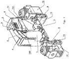
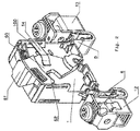
- the disconnection device according to the exemplary embodiment can be part of a surge arrester in the form of a plug-in part, as shown in FIG Figure 1 and 2 is indicated.
- the plug-in part shown here does not yet have an outer housing in order to make the structure and function of the separating device clear.
- the plug-in part has a support body 1, which has a chamber-like recess on one side, which has at least one diverter element.
- the support body has an opening 2 which allows access to a contact point 3 of the arrester element.
- the thermal separation point known per se is implemented in this area.
- the support body 1 has a curved guide 4 for receiving a spring 5 which generates a pretensioning force. It should also be noted that the spring 5 is supported at one end on a stop of an insulating separating block 6 designed as a rotary slide valve.
- the rotary slide valve sits on an axis of rotation 7, which can be designed as an extension and thus an integral element of the support body 1.
- the mating contacts 10 and 11 are connected to external screw terminals 12 and 13 known per se or are part of them.
- the switching tongue of the thermal separation point is designed as a straight, elongated, metallic, resiliently elastic separation strip 14.
- connection to the contact surface 3 of the diverter element takes place, as explained, by means of the thermal separation point, specifically via the broad side of a first separation strip end 140.
- the recess 15 here essentially corresponds to the cross-sectional area of the second separating strip end 141 and is designed to be complementary to this end.
- the separating block 6 is subject to a position shift; this is in the Figures 1 and 2 traceable by moving to the left.
- the separating strip lifts off the contact point 3 with its first separating strip end 140. Furthermore, the separating block 6 enters the resulting space with its area 60 (see FIG Figure 2 ).
- the shift in position of the separating block 6 can be seen through a viewing window (not shown in the figures) in an outer housing (not shown) that encloses the support body 1.
- a display surface 61 is formed on the separating block 6.
- the separating block 6 is, as from the Figures 1 and 2 understandable, designed as a rotary valve. At its edge 62 pointing towards the thermal separation point, the separating block 6 can have a flattening in the form of an inclined surface or a wedge surface in order to optimize the penetration into the separation point area and the separation process.
Landscapes
- Engineering & Computer Science (AREA)
- Chemical & Material Sciences (AREA)
- Combustion & Propulsion (AREA)
- Microelectronics & Electronic Packaging (AREA)
- Physics & Mathematics (AREA)
- Electromagnetism (AREA)
- Fuses (AREA)
- Thermistors And Varistors (AREA)
Priority Applications (2)
| Application Number | Priority Date | Filing Date | Title |
|---|---|---|---|
| SI201930096T SI3673497T1 (sl) | 2018-06-18 | 2019-05-20 | Odklopna naprava za prenapetostni odvodnik |
| PL19725355T PL3673497T3 (pl) | 2018-06-18 | 2019-05-20 | Urządzenie separujące do ogranicznika przepięć |
Applications Claiming Priority (2)
| Application Number | Priority Date | Filing Date | Title |
|---|---|---|---|
| DE102018114564.0A DE102018114564B4 (de) | 2018-06-18 | 2018-06-18 | Überspannungsableiter |
| PCT/EP2019/062906 WO2019242959A1 (de) | 2018-06-18 | 2019-05-20 | Abtrennvorrichtung für einen überspannungsableiter |
Publications (2)
| Publication Number | Publication Date |
|---|---|
| EP3673497A1 EP3673497A1 (de) | 2020-07-01 |
| EP3673497B1 true EP3673497B1 (de) | 2021-07-14 |
Family
ID=66625195
Family Applications (1)
| Application Number | Title | Priority Date | Filing Date |
|---|---|---|---|
| EP19725355.2A Active EP3673497B1 (de) | 2018-06-18 | 2019-05-20 | Abtrennvorrichtung für einen überspannungsableiter |
Country Status (9)
| Country | Link |
|---|---|
| US (1) | US11476071B2 (ja) |
| EP (1) | EP3673497B1 (ja) |
| JP (1) | JP2021527929A (ja) |
| CN (1) | CN112514008B (ja) |
| DE (1) | DE102018114564B4 (ja) |
| ES (1) | ES2887304T3 (ja) |
| PL (1) | PL3673497T3 (ja) |
| SI (1) | SI3673497T1 (ja) |
| WO (1) | WO2019242959A1 (ja) |
Families Citing this family (1)
| Publication number | Priority date | Publication date | Assignee | Title |
|---|---|---|---|---|
| CN214479600U (zh) * | 2021-01-08 | 2021-10-22 | 厦门赛尔特电子有限公司 | 一种石墨浪涌保护器 |
Family Cites Families (24)
| Publication number | Priority date | Publication date | Assignee | Title |
|---|---|---|---|---|
| JPS547389A (en) | 1977-06-17 | 1979-01-20 | Nittan Co Ltd | Photoelectric smoke detector |
| JPS5611335Y2 (ja) * | 1977-06-18 | 1981-03-13 | ||
| US6430019B1 (en) * | 1998-06-08 | 2002-08-06 | Ferraz S.A. | Circuit protection device |
| US6040971A (en) * | 1998-06-08 | 2000-03-21 | Martenson; Kenneth R. | Circuit protection device |
| WO2005112050A1 (fr) * | 2004-04-19 | 2005-11-24 | Soule Protection Surtensions | Dispositif de protection contre les surtensions pourvu de moyens de coupure d’arc |
| US7477503B2 (en) * | 2005-04-30 | 2009-01-13 | Efi Electronics Corporation | Circuit protection device |
| BRPI0614137A2 (pt) * | 2005-08-05 | 2012-11-20 | Kiwa Spol S R O | proteÇço de sobrevoltagem com sinalizaÇço de estado |
| DE102006036598A1 (de) | 2006-04-26 | 2007-10-31 | Dehn + Söhne Gmbh + Co. Kg | Verfahren zur Dimensionierung einer Abtrennvorrichtung für Überspannungsableiter |
| US7483252B2 (en) * | 2006-12-05 | 2009-01-27 | Ferraz Shawmut S.A. | Circuit protection device |
| DE102007042991B4 (de) * | 2007-06-11 | 2009-09-17 | Dehn + Söhne Gmbh + Co. Kg | Überspannungsschutzgerät mit im thermischen Überlastfall aktivierter mechanischer Abtrennvorrichtung |
| DE102008048644B4 (de) * | 2008-08-01 | 2017-08-24 | DEHN + SÖHNE GmbH + Co. KG. | Überspannungsschutzgerät mit einem oder mehreren parallel geschalteten, in einer baulichen Einheit befindlichen überspannungsbegrenzenden Elementen |
| US8031456B2 (en) * | 2009-05-12 | 2011-10-04 | Ceramate Technical Co., Ltd. | Explosion-roof and flameproof pullout safety surge absorbing module |
| US8836464B2 (en) * | 2009-06-24 | 2014-09-16 | Ceramate Technical Co., Ltd. | Explosion-proof and flameproof ejection type safety surge-absorbing module |
| FR2958788B1 (fr) * | 2010-04-09 | 2015-01-30 | Abb France | Varistance comprenant une electrode avec une partie en saillie formant pole et parafoudre comprenant une telle varistance |
| US8502637B2 (en) * | 2010-09-22 | 2013-08-06 | Thomas & Betts International, Inc. | Surge protective device with thermal decoupler and arc suppression |
| DE102011018556A1 (de) * | 2011-02-18 | 2012-08-23 | Dehn + Söhne Gmbh + Co. Kg | Überspannungsschutzeinrichtung, umfassend mindestens einen Überspannungsableiter |
| US9165702B2 (en) * | 2011-03-07 | 2015-10-20 | James P. Hagerty | Thermally-protected varistor |
| DE112011105340T5 (de) * | 2011-06-17 | 2014-03-13 | Littelfuse, Inc. | Thermische Metalloxidvaristor-Schaltungsschutzeinrichtung |
| DE102013006052B4 (de) * | 2013-02-08 | 2016-08-04 | DEHN + SÖHNE GmbH + Co. KG. | Überspannungsschutzgerät |
| DE102013022348B4 (de) * | 2013-10-22 | 2016-01-07 | Dehn + Söhne Gmbh + Co. Kg | Überspannungsschutzeinrichtung, aufweisend mindestens einen Überspannungsableiter und eine, mit dem Überspannungsableiter in Reihe geschaltete, thermisch auslösbare Schalteinrichtung |
| DE202014002496U1 (de) * | 2014-03-20 | 2014-04-17 | Dehn + Söhne Gmbh + Co. Kg | Überspannungsschutzeinrichtung, umfassend mindestens einen Überspannungsableiter und eine dem Überspannungsableiter parallel geschaltete, thermisch auslösbare, federvorgespannte Kurzschliessschalteinrichtung |
| DE202014103262U1 (de) | 2014-07-15 | 2014-07-30 | Phoenix Contact Gmbh & Co. Kg | Überspannungsschutzelement |
| CN204131121U (zh) * | 2014-11-10 | 2015-01-28 | 毛小毛 | 具有高结构稳定性的电涌抑制装置 |
| DE202016107504U1 (de) * | 2016-06-22 | 2017-03-02 | Dehn + Söhne Gmbh + Co. Kg | Überspannungsschutzanordnung mit mindestens einem, auf einer ersten Seite einer n-eckigen Trägerplatte angeordneten, scheibenförmigen Varistor |
-
2018
- 2018-06-18 DE DE102018114564.0A patent/DE102018114564B4/de active Active
-
2019
- 2019-05-20 CN CN201980048162.3A patent/CN112514008B/zh active Active
- 2019-05-20 SI SI201930096T patent/SI3673497T1/sl unknown
- 2019-05-20 US US17/251,895 patent/US11476071B2/en active Active
- 2019-05-20 JP JP2020570528A patent/JP2021527929A/ja active Pending
- 2019-05-20 PL PL19725355T patent/PL3673497T3/pl unknown
- 2019-05-20 WO PCT/EP2019/062906 patent/WO2019242959A1/de unknown
- 2019-05-20 ES ES19725355T patent/ES2887304T3/es active Active
- 2019-05-20 EP EP19725355.2A patent/EP3673497B1/de active Active
Non-Patent Citations (1)
| Title |
|---|
| None * |
Also Published As
| Publication number | Publication date |
|---|---|
| WO2019242959A1 (de) | 2019-12-26 |
| DE102018114564B4 (de) | 2023-01-19 |
| CN112514008B (zh) | 2022-07-19 |
| JP2021527929A (ja) | 2021-10-14 |
| CN112514008A (zh) | 2021-03-16 |
| ES2887304T3 (es) | 2021-12-22 |
| SI3673497T1 (sl) | 2021-11-30 |
| EP3673497A1 (de) | 2020-07-01 |
| DE102018114564A1 (de) | 2019-12-19 |
| US11476071B2 (en) | 2022-10-18 |
| PL3673497T3 (pl) | 2021-12-06 |
| US20210125804A1 (en) | 2021-04-29 |
Similar Documents
| Publication | Publication Date | Title |
|---|---|---|
| DE19941190B4 (de) | Wärmeschutzsicherung | |
| DE69606706T2 (de) | Elektrische anschlussklemme | |
| DE102008031917B4 (de) | Überspannungschutzelement | |
| DE102008029670B4 (de) | Überspannungsschutzelement | |
| WO2007125000A1 (de) | Verfahren zur dimensionierung einer abtrennvorrichtung für überspannungsableiter | |
| DE202014103262U1 (de) | Überspannungsschutzelement | |
| DE69515128T2 (de) | Anschlussklemme auf sammelschienen für lastschalter oder mehrpolige trennbare systeme | |
| DE102013022348B4 (de) | Überspannungsschutzeinrichtung, aufweisend mindestens einen Überspannungsableiter und eine, mit dem Überspannungsableiter in Reihe geschaltete, thermisch auslösbare Schalteinrichtung | |
| DE102018215879B4 (de) | Steckverbindung mit Redundanz sowie Fahrzeug mit einer solchen | |
| EP1291979B1 (de) | Elektrisches Anschlusselement | |
| DE102014003113B3 (de) | Steckverbindungsteil mit Klammerelementen | |
| EP3673497B1 (de) | Abtrennvorrichtung für einen überspannungsableiter | |
| DE102017124224B4 (de) | Überspannungsschutzgerät | |
| DE1181299B (de) | Elektrothermische Schaltvorrichtung | |
| DE1915721B2 (de) | Thermostatische schaltvorrichtung | |
| DE102006043795B3 (de) | Elektrischer Mikroschalter | |
| DE102019112680B4 (de) | Überspannungsschutzgerät | |
| DE202018006119U1 (de) | Abtrennvorrichtung für einen Überspannungsableiter | |
| WO2002065494A1 (de) | Schaltkontaktanordnung | |
| DE102017112429B4 (de) | Überspannungsschutzelement | |
| AT502415B1 (de) | Prüftaster, anschlussverbindung für einen prüftaster, schutzschalter und verfahren zur herstellung eines schutzschalters | |
| DE102015103113A1 (de) | Trennklemme | |
| DE102019106960B4 (de) | Elektronisches Bauteil | |
| DE202022103235U1 (de) | Baugruppe für ein Überspannungsschutzgerät sowie Überspannungsschutzgerät | |
| DE102020121591A1 (de) | Thermisch aktivierbare Abtrenneinrichtung für ein elektronisches Bauelement, insbesondere für einen Überspannungsableiter |
Legal Events
| Date | Code | Title | Description |
|---|---|---|---|
| STAA | Information on the status of an ep patent application or granted ep patent |
Free format text: STATUS: UNKNOWN |
|
| STAA | Information on the status of an ep patent application or granted ep patent |
Free format text: STATUS: THE INTERNATIONAL PUBLICATION HAS BEEN MADE |
|
| PUAI | Public reference made under article 153(3) epc to a published international application that has entered the european phase |
Free format text: ORIGINAL CODE: 0009012 |
|
| STAA | Information on the status of an ep patent application or granted ep patent |
Free format text: STATUS: REQUEST FOR EXAMINATION WAS MADE |
|
| 17P | Request for examination filed |
Effective date: 20200325 |
|
| AK | Designated contracting states |
Kind code of ref document: A1 Designated state(s): AL AT BE BG CH CY CZ DE DK EE ES FI FR GB GR HR HU IE IS IT LI LT LU LV MC MK MT NL NO PL PT RO RS SE SI SK SM TR |
|
| AX | Request for extension of the european patent |
Extension state: BA ME |
|
| STAA | Information on the status of an ep patent application or granted ep patent |
Free format text: STATUS: EXAMINATION IS IN PROGRESS |
|
| 17Q | First examination report despatched |
Effective date: 20200714 |
|
| STAA | Information on the status of an ep patent application or granted ep patent |
Free format text: STATUS: EXAMINATION IS IN PROGRESS |
|
| GRAP | Despatch of communication of intention to grant a patent |
Free format text: ORIGINAL CODE: EPIDOSNIGR1 |
|
| STAA | Information on the status of an ep patent application or granted ep patent |
Free format text: STATUS: GRANT OF PATENT IS INTENDED |
|
| DAV | Request for validation of the european patent (deleted) | ||
| DAX | Request for extension of the european patent (deleted) | ||
| INTG | Intention to grant announced |
Effective date: 20210205 |
|
| GRAS | Grant fee paid |
Free format text: ORIGINAL CODE: EPIDOSNIGR3 |
|
| GRAA | (expected) grant |
Free format text: ORIGINAL CODE: 0009210 |
|
| STAA | Information on the status of an ep patent application or granted ep patent |
Free format text: STATUS: THE PATENT HAS BEEN GRANTED |
|
| AK | Designated contracting states |
Kind code of ref document: B1 Designated state(s): AL AT BE BG CH CY CZ DE DK EE ES FI FR GB GR HR HU IE IS IT LI LT LU LV MC MK MT NL NO PL PT RO RS SE SI SK SM TR |
|
| REG | Reference to a national code |
Ref country code: GB Ref legal event code: FG4D Free format text: NOT ENGLISH |
|
| REG | Reference to a national code |
Ref country code: IE Ref legal event code: FG4D Free format text: LANGUAGE OF EP DOCUMENT: GERMAN |
|
| REG | Reference to a national code |
Ref country code: DE Ref legal event code: R096 Ref document number: 502019001819 Country of ref document: DE |
|
| REG | Reference to a national code |
Ref country code: AT Ref legal event code: REF Ref document number: 1411299 Country of ref document: AT Kind code of ref document: T Effective date: 20210815 |
|
| REG | Reference to a national code |
Ref country code: LT Ref legal event code: MG9D |
|
| REG | Reference to a national code |
Ref country code: NL Ref legal event code: MP Effective date: 20210714 |
|
| REG | Reference to a national code |
Ref country code: ES Ref legal event code: FG2A Ref document number: 2887304 Country of ref document: ES Kind code of ref document: T3 Effective date: 20211222 |
|
| PG25 | Lapsed in a contracting state [announced via postgrant information from national office to epo] |
Ref country code: SE Free format text: LAPSE BECAUSE OF FAILURE TO SUBMIT A TRANSLATION OF THE DESCRIPTION OR TO PAY THE FEE WITHIN THE PRESCRIBED TIME-LIMIT Effective date: 20210714 Ref country code: RS Free format text: LAPSE BECAUSE OF FAILURE TO SUBMIT A TRANSLATION OF THE DESCRIPTION OR TO PAY THE FEE WITHIN THE PRESCRIBED TIME-LIMIT Effective date: 20210714 Ref country code: BG Free format text: LAPSE BECAUSE OF FAILURE TO SUBMIT A TRANSLATION OF THE DESCRIPTION OR TO PAY THE FEE WITHIN THE PRESCRIBED TIME-LIMIT Effective date: 20211014 Ref country code: LT Free format text: LAPSE BECAUSE OF FAILURE TO SUBMIT A TRANSLATION OF THE DESCRIPTION OR TO PAY THE FEE WITHIN THE PRESCRIBED TIME-LIMIT Effective date: 20210714 Ref country code: HR Free format text: LAPSE BECAUSE OF FAILURE TO SUBMIT A TRANSLATION OF THE DESCRIPTION OR TO PAY THE FEE WITHIN THE PRESCRIBED TIME-LIMIT Effective date: 20210714 Ref country code: FI Free format text: LAPSE BECAUSE OF FAILURE TO SUBMIT A TRANSLATION OF THE DESCRIPTION OR TO PAY THE FEE WITHIN THE PRESCRIBED TIME-LIMIT Effective date: 20210714 Ref country code: PT Free format text: LAPSE BECAUSE OF FAILURE TO SUBMIT A TRANSLATION OF THE DESCRIPTION OR TO PAY THE FEE WITHIN THE PRESCRIBED TIME-LIMIT Effective date: 20211115 Ref country code: NL Free format text: LAPSE BECAUSE OF FAILURE TO SUBMIT A TRANSLATION OF THE DESCRIPTION OR TO PAY THE FEE WITHIN THE PRESCRIBED TIME-LIMIT Effective date: 20210714 Ref country code: NO Free format text: LAPSE BECAUSE OF FAILURE TO SUBMIT A TRANSLATION OF THE DESCRIPTION OR TO PAY THE FEE WITHIN THE PRESCRIBED TIME-LIMIT Effective date: 20211014 |
|
| REG | Reference to a national code |
Ref country code: DE Ref legal event code: R081 Ref document number: 502019001819 Country of ref document: DE Owner name: DEHN SE, DE Free format text: FORMER OWNER: DEHN SE + CO KG, 92318 NEUMARKT, DE |
|
| PG25 | Lapsed in a contracting state [announced via postgrant information from national office to epo] |
Ref country code: LV Free format text: LAPSE BECAUSE OF FAILURE TO SUBMIT A TRANSLATION OF THE DESCRIPTION OR TO PAY THE FEE WITHIN THE PRESCRIBED TIME-LIMIT Effective date: 20210714 Ref country code: GR Free format text: LAPSE BECAUSE OF FAILURE TO SUBMIT A TRANSLATION OF THE DESCRIPTION OR TO PAY THE FEE WITHIN THE PRESCRIBED TIME-LIMIT Effective date: 20211015 |
|
| REG | Reference to a national code |
Ref country code: DE Ref legal event code: R097 Ref document number: 502019001819 Country of ref document: DE |
|
| RAP2 | Party data changed (patent owner data changed or rights of a patent transferred) |
Owner name: DEHN SE |
|
| PG25 | Lapsed in a contracting state [announced via postgrant information from national office to epo] |
Ref country code: DK Free format text: LAPSE BECAUSE OF FAILURE TO SUBMIT A TRANSLATION OF THE DESCRIPTION OR TO PAY THE FEE WITHIN THE PRESCRIBED TIME-LIMIT Effective date: 20210714 |
|
| PLBE | No opposition filed within time limit |
Free format text: ORIGINAL CODE: 0009261 |
|
| STAA | Information on the status of an ep patent application or granted ep patent |
Free format text: STATUS: NO OPPOSITION FILED WITHIN TIME LIMIT |
|
| PG25 | Lapsed in a contracting state [announced via postgrant information from national office to epo] |
Ref country code: SM Free format text: LAPSE BECAUSE OF FAILURE TO SUBMIT A TRANSLATION OF THE DESCRIPTION OR TO PAY THE FEE WITHIN THE PRESCRIBED TIME-LIMIT Effective date: 20210714 Ref country code: SK Free format text: LAPSE BECAUSE OF FAILURE TO SUBMIT A TRANSLATION OF THE DESCRIPTION OR TO PAY THE FEE WITHIN THE PRESCRIBED TIME-LIMIT Effective date: 20210714 Ref country code: RO Free format text: LAPSE BECAUSE OF FAILURE TO SUBMIT A TRANSLATION OF THE DESCRIPTION OR TO PAY THE FEE WITHIN THE PRESCRIBED TIME-LIMIT Effective date: 20210714 Ref country code: EE Free format text: LAPSE BECAUSE OF FAILURE TO SUBMIT A TRANSLATION OF THE DESCRIPTION OR TO PAY THE FEE WITHIN THE PRESCRIBED TIME-LIMIT Effective date: 20210714 Ref country code: CZ Free format text: LAPSE BECAUSE OF FAILURE TO SUBMIT A TRANSLATION OF THE DESCRIPTION OR TO PAY THE FEE WITHIN THE PRESCRIBED TIME-LIMIT Effective date: 20210714 Ref country code: AL Free format text: LAPSE BECAUSE OF FAILURE TO SUBMIT A TRANSLATION OF THE DESCRIPTION OR TO PAY THE FEE WITHIN THE PRESCRIBED TIME-LIMIT Effective date: 20210714 |
|
| 26N | No opposition filed |
Effective date: 20220419 |
|
| REG | Reference to a national code |
Ref country code: CH Ref legal event code: PL |
|
| REG | Reference to a national code |
Ref country code: BE Ref legal event code: MM Effective date: 20220531 |
|
| PG25 | Lapsed in a contracting state [announced via postgrant information from national office to epo] |
Ref country code: MC Free format text: LAPSE BECAUSE OF FAILURE TO SUBMIT A TRANSLATION OF THE DESCRIPTION OR TO PAY THE FEE WITHIN THE PRESCRIBED TIME-LIMIT Effective date: 20210714 Ref country code: LU Free format text: LAPSE BECAUSE OF NON-PAYMENT OF DUE FEES Effective date: 20220520 Ref country code: CH Free format text: LAPSE BECAUSE OF NON-PAYMENT OF DUE FEES Effective date: 20220531 Ref country code: LI Free format text: LAPSE BECAUSE OF NON-PAYMENT OF DUE FEES Effective date: 20220531 |
|
| PG25 | Lapsed in a contracting state [announced via postgrant information from national office to epo] |
Ref country code: SI Free format text: LAPSE BECAUSE OF NON-PAYMENT OF DUE FEES Effective date: 20220521 |
|
| PG25 | Lapsed in a contracting state [announced via postgrant information from national office to epo] |
Ref country code: IE Free format text: LAPSE BECAUSE OF NON-PAYMENT OF DUE FEES Effective date: 20220520 |
|
| PG25 | Lapsed in a contracting state [announced via postgrant information from national office to epo] |
Ref country code: BE Free format text: LAPSE BECAUSE OF NON-PAYMENT OF DUE FEES Effective date: 20220531 |
|
| REG | Reference to a national code |
Ref country code: ES Ref legal event code: FD2A Effective date: 20230626 |
|
| PG25 | Lapsed in a contracting state [announced via postgrant information from national office to epo] |
Ref country code: ES Free format text: LAPSE BECAUSE OF NON-PAYMENT OF DUE FEES Effective date: 20220521 |
|
| PGFP | Annual fee paid to national office [announced via postgrant information from national office to epo] |
Ref country code: IT Payment date: 20230531 Year of fee payment: 5 |
|
| REG | Reference to a national code |
Ref country code: AT Ref legal event code: PC Ref document number: 1411299 Country of ref document: AT Kind code of ref document: T Owner name: DEHN SE, DE Effective date: 20230822 |
|
| GBPC | Gb: european patent ceased through non-payment of renewal fee |
Effective date: 20230520 |
|
| PG25 | Lapsed in a contracting state [announced via postgrant information from national office to epo] |
Ref country code: MK Free format text: LAPSE BECAUSE OF FAILURE TO SUBMIT A TRANSLATION OF THE DESCRIPTION OR TO PAY THE FEE WITHIN THE PRESCRIBED TIME-LIMIT Effective date: 20210714 Ref country code: CY Free format text: LAPSE BECAUSE OF FAILURE TO SUBMIT A TRANSLATION OF THE DESCRIPTION OR TO PAY THE FEE WITHIN THE PRESCRIBED TIME-LIMIT Effective date: 20210714 Ref country code: GB Free format text: LAPSE BECAUSE OF NON-PAYMENT OF DUE FEES Effective date: 20230520 |
|
| PG25 | Lapsed in a contracting state [announced via postgrant information from national office to epo] |
Ref country code: PL Free format text: LAPSE BECAUSE OF NON-PAYMENT OF DUE FEES Effective date: 20220520 Ref country code: HU Free format text: LAPSE BECAUSE OF FAILURE TO SUBMIT A TRANSLATION OF THE DESCRIPTION OR TO PAY THE FEE WITHIN THE PRESCRIBED TIME-LIMIT; INVALID AB INITIO Effective date: 20190520 |
|
| PG25 | Lapsed in a contracting state [announced via postgrant information from national office to epo] |
Ref country code: TR Free format text: LAPSE BECAUSE OF FAILURE TO SUBMIT A TRANSLATION OF THE DESCRIPTION OR TO PAY THE FEE WITHIN THE PRESCRIBED TIME-LIMIT Effective date: 20210714 |
|
| PGFP | Annual fee paid to national office [announced via postgrant information from national office to epo] |
Ref country code: DE Payment date: 20240517 Year of fee payment: 6 |
|
| PGFP | Annual fee paid to national office [announced via postgrant information from national office to epo] |
Ref country code: AT Payment date: 20240517 Year of fee payment: 6 |
|
| PGFP | Annual fee paid to national office [announced via postgrant information from national office to epo] |
Ref country code: FR Payment date: 20240516 Year of fee payment: 6 |