EP3672918B1 - Vorrichtung zum präzisen positionsgetreuen transport von empfindlichen heissen glaswaren - Google Patents
Vorrichtung zum präzisen positionsgetreuen transport von empfindlichen heissen glaswaren Download PDFInfo
- Publication number
- EP3672918B1 EP3672918B1 EP18742479.1A EP18742479A EP3672918B1 EP 3672918 B1 EP3672918 B1 EP 3672918B1 EP 18742479 A EP18742479 A EP 18742479A EP 3672918 B1 EP3672918 B1 EP 3672918B1
- Authority
- EP
- European Patent Office
- Prior art keywords
- conveyor belt
- openings
- glassware
- transport
- der
- Prior art date
- Legal status (The legal status is an assumption and is not a legal conclusion. Google has not performed a legal analysis and makes no representation as to the accuracy of the status listed.)
- Active
Links
Images

Classifications
-
- C—CHEMISTRY; METALLURGY
- C03—GLASS; MINERAL OR SLAG WOOL
- C03B—MANUFACTURE, SHAPING, OR SUPPLEMENTARY PROCESSES
- C03B25/00—Annealing glass products
- C03B25/04—Annealing glass products in a continuous way
- C03B25/06—Annealing glass products in a continuous way with horizontal displacement of the glass products
-
- C—CHEMISTRY; METALLURGY
- C03—GLASS; MINERAL OR SLAG WOOL
- C03B—MANUFACTURE, SHAPING, OR SUPPLEMENTARY PROCESSES
- C03B35/00—Transporting of glass products during their manufacture, e.g. hot glass lenses, prisms
- C03B35/04—Transporting of hot hollow or semi-hollow glass products
- C03B35/06—Feeding of hot hollow glass products into annealing or heating kilns
- C03B35/062—Feeding of hot hollow glass products into annealing or heating kilns using conveyors, e.g. chain- or roller conveyors, dead-plates
-
- C—CHEMISTRY; METALLURGY
- C03—GLASS; MINERAL OR SLAG WOOL
- C03B—MANUFACTURE, SHAPING, OR SUPPLEMENTARY PROCESSES
- C03B35/00—Transporting of glass products during their manufacture, e.g. hot glass lenses, prisms
- C03B35/04—Transporting of hot hollow or semi-hollow glass products
- C03B35/06—Feeding of hot hollow glass products into annealing or heating kilns
- C03B35/062—Feeding of hot hollow glass products into annealing or heating kilns using conveyors, e.g. chain- or roller conveyors, dead-plates
- C03B35/064—Feeding of hot hollow glass products into annealing or heating kilns using conveyors, e.g. chain- or roller conveyors, dead-plates specially adapted as a lehr loader
-
- C—CHEMISTRY; METALLURGY
- C03—GLASS; MINERAL OR SLAG WOOL
- C03B—MANUFACTURE, SHAPING, OR SUPPLEMENTARY PROCESSES
- C03B35/00—Transporting of glass products during their manufacture, e.g. hot glass lenses, prisms
- C03B35/26—Transporting of glass tubes or rods
Definitions
- the invention relates to a device for precisely positioning sensitive hot glassware according to the preamble of claim 1.
- Sensitive glassware is understood to mean in particular glass articles made of tubular glass, such as vials, syringes, cartridges and the like, which are used, for example, in the field of medicine and pharmacy. The highest demands are placed on the quality and traceability of this glassware.
- the glassware is first shaped and then placed on a conveyor belt. After the molding process, these glassware are placed in a relaxation furnace in the next processing step in order to prevent tension in the glass that can otherwise arise when it cools.
- the glass items are placed on a transport system of the expansion furnace and precisely driven through the furnace tunnel.
- the transport system usually consists of a revolving conveyor belt made of round perforated and shaped sheet metal strips, on which the glass items can be arranged, while the conveyor belt is driven by laterally arranged chains (drive chain). Depending on the product, the glass items are placed on so-called bars.
- heating systems are then arranged below and above the transport system.
- the heat transfer from the heating systems to the product usually takes place in a mixture of radiation and natural convection.
- the perforations in the sheet metal strips enable the heat transfer from the heating systems arranged below to the glass items.
- the perforation reduces the mass of the transport system to be heated.
- the perforations are many, offset from one another arranged round perforations, these being designed in such a way that the greatest possible and homogeneous throughput of heat transfer to each area of the glass article is guaranteed.
- the maximum diameter of this perforation is dimensioned in such a way that neither glass articles can fall through nor are their positioning impaired.
- WO 2017/093077 A1 discloses variously designed conveyor belts which are formed from a plurality of article carriers or carrier strips.
- the invention is based on the object of avoiding the aforementioned disadvantages and not, or as little as possible, obstructing the flow of heat within the transport system. This object is achieved by the characterizing features of claim 1, which have the following special meaning.
- the conveyor belt is designed in such a way that the openings are located as elongated recesses arranged longitudinally or transversely in the conveyor belt, so that the flow of heat within the material is not hindered or interrupted by the openings.
- the flow of heat can thus take place unhindered both in the longitudinal and in the transverse direction of the conveyor belt, the flow of heat taking place quasi laterally past the openings.
- the openings are designed in such a way that they enable good heat transfer from the heating system arranged below the conveyor belt to the glassware.
- the openings are designed as a plurality of rows of elongated holes arranged parallel to one another.
- the conveyor belt can consist of stamped sheet metal, for example. Sufficient heat can then be transported from the heating system to the glassware through the elongated holes. The heat transfer within the conveyor belt is not hindered by the openings. A "zigzag" path is also not necessary, since the heat transport takes place laterally past the elongated openings.
- the openings are preferably arranged perpendicular to the direction of movement of the conveyor belt.
- the conveyor belt consists of several wire elements connected to one another, between which the openings are located. This results in a grid-like structure of the conveyor belt. Since there are no interruptions within a wire element, the flow of heat is not hindered.
- the openings are preferably arranged transversely to the direction of movement of the conveyor belt.
- webs for receiving and positioning the glassware can be provided.
- a piece of glassware for example a glass bottle with the neck, can then rest on each of these webs.
- the conveyor belt is preferably a circulating conveyor belt. These have proven themselves in the glass industry and are practical in use.
- the conveyor belt can be driven, for example, by means of one or more drive chains.
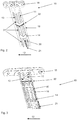
- Fig. 1 shows a section from a conveyor belt 10 according to the prior art.
- An article carrier 16 is shown which has a multiplicity of openings designed as round holes 11 '. These round holes 11 'are arranged offset to one another. Both in the longitudinal 21 and in the transverse direction 22, the heat flow that takes place through the material of the conveyor belt 10 has to find a way around these round holes 11 '.
- the heat flow in the longitudinal direction 21 and transverse direction 22 in FIG Fig. 1 shown as a bold line. Through this "zigzag" path of the Heat flow leads to the problems mentioned at the beginning and the article carriers 16 bend.
- the conveyor belt 10 consists of a shaped sheet metal into which several elongated holes 30 have been made in rows 31.
- the elongated holes 30 are arranged here transversely to the transport direction 12 of the conveyor belt 10.
- the heat flow can now take place in the longitudinal direction 21 and in the transverse direction 22, and in the process flows sideways past the elongated holes 30, as it were. Thermal deformation is thus minimized.
- Fig. 2 another drive chain 15, which is used to drive the conveyor belt 10 consisting of article carriers 16, and several webs 14 on which the glassware located on the conveyor belt 10 can be supported.
- FIG. 3 Another embodiment of the conveyor belt 10 according to the invention is shown Fig. 3 .
- the conveyor belt 10 is formed from a plurality of wire elements 40 which have the elongated holes 13 between them. This creates a grid-like structure. Since the individual wire elements 40 are continuous and not interrupted, the heat flow through these wire elements 40 can also take place in the longitudinal direction 21 and in the transverse direction 22. In this embodiment, too, a drive chain 15 and several webs 14 are again provided.
Landscapes
- Chemical & Material Sciences (AREA)
- Engineering & Computer Science (AREA)
- Materials Engineering (AREA)
- Organic Chemistry (AREA)
- Belt Conveyors (AREA)
- Re-Forming, After-Treatment, Cutting And Transporting Of Glass Products (AREA)
- Chain Conveyers (AREA)
Description
- Die Erfindung betrifft eine Vorrichtung zum präzisen positionsgetreuen Transport von empfindlichen heißen Glaswaren gemäß dem Oberbegriff von Patentanspruch 1. Unter empfindlichen Glaswaren werden insbesondere Glasartikel aus Röhrenglas, wie Phiolen, Spritzen, Karpulen und Ähnliches verstanden, welche beispielsweise im Bereich der Medizin und Pharmazie eingesetzt werden. An die Qualität und Rückverfolgbarkeit dieser Glaswaren werden höchste Anforderungen gestellt. Die Glaswaren werden dabei zunächst geformt und dann auf ein Transportband verbracht. Nach dem Formprozess werden diese Glaswaren im nächsten Bearbeitungsschritt in einen Entspannungsofen gebracht, um Spannungen im Glas, die sonst beim Abkühlen entstehen können, zu verhindern.
- Dazu werden die Glasartikel auf einem Transportsystem des Entspannungsofens abgelegt und präzise durch den Ofentunnel gefahren. Das Transportsystem besteht dabei üblicherweise aus einem umlaufenden Transportband aus rundgelochten und geformten Blechstreifen, auf welchem die Glasartikel anordbar sind, während das Transportband durch seitlich angeordnete Ketten (Antriebskette) angetrieben wird. Produktbedingt werden die Glasartikel auf sogenannten Stegen abgelegt.
- Im Ofentunnel selbst sind dann unterhalb und oberhalb des Transportsystems Heizungssysteme angeordnet. Der Wärmetransfer von den Heizungssystemen zum Produkt erfolgt hierbei üblicherweise in einer Mischung aus Strahlung und natürlicher Konvektion.
- Die Lochungen in den Blechstreifen ermöglichen den Wärmetransfer der unterhalb angeordneten Heizungssysteme zu den Glasartikeln. Außerdem wird durch die Lochung die aufzuheizende Masse des Transportsystems reduziert. Üblicherweise sind die Lochungen dabei als viele, versetzt zu einander angeordneten Rundlochungen ausgeführt, wobei diese so ausgestaltet sind, dass ein möglichst großer und homogener Durchsatz des Wärmetransfers zu jedem Bereich der Glasartikel gewährleistet ist. Der maximale Durchmesser dieser Lochung ist dabei so bemessen, dass weder Glasartikel hindurch fallen können noch in ihrer Positionierung beeinträchtigt werden.
-
WO 2017/093077 A1 offenbart verschieden gestaltete Transportbänder, die aus mehreren Artikelträgern oder Trägerleisten ausgebildet sind. - Bei bekannten Transportsystemen kann es jedoch zu folgenden Nachteilen kommen:
- Bei dem Erwärmen und Abkühlen der Blechleisten entstehen temporäre Spannungen. Diese entstehen dadurch, dass die Lochungen den Wärmefluss innerhalb der Blechleiste behindern und sich dadurch temporär Bereiche unterschiedlicher Temperatur bilden. Der Wärmefluss muss sich quasi im "Zick-Zack" durch das Lochbild kämpfen und wird somit verlangsamt.
- Als Folge der Spannungen verbiegen sich die Blechleisten temporär um mehrere Millimeter in horizontaler und/oder vertikaler Richtung.
- Die Höhe der Verbiegung kann im Extremfall bis zu mehrere Zentimeter betragen und ist dabei abhängig vom Widerstandsmoment der Blechleiste, der Länge der Blechleiste, des thermischen Ausdehnungskoeffizienten und der Wärmeleifähigkeit des verwendeten Materials sowie der Anordnung und der Anzahl der Bohrungen in der Blechleiste.
- Durch das Verbiegen ändern sich die Gefügeeigenschaften der Blechleisten, es entsteht harter Verformungsmartensit, der zu einer dauerhaften, plastischen Verformung der Blechleisten führt.
- Je nach Größe der Verbiegung verlieren die auf dem Transportsystem befindlichen Waren ihre Position und können nicht mehr automatisiert abgenommen werden. Auch eine Kollision mit Bestandteilen des Ofens, insbesondere am Tunnel-Eingang- bzw. -Ausgang oder auch mit anderen Waren kann vorkommen. Dies führt zu einer Beschädigung der Waren.
- Der Erfindung liegt die Aufgabe zugrunde, die vorerwähnten Nachteile zu vermeiden und den Wärmefluss innerhalb der Transportsystems nicht oder möglichst wenig zu behindern. Diese Aufgabe wird durch die kennzeichnenden Merkmale von Anspruch 1 gelöst, denen folgende besondere Bedeutung zukommt.
- Das Transportband ist erfindungsgemäß so ausgestaltet, dass die Öffnungen als längs oder quer angeordnete längliche Ausnehmungen im Transportband befindlich sind, so dass der Wärmefluss innerhalb des Materials nicht von den Öffnungen behindert oder unterbrochen wird. Erfindungsgemäß kann so der Wärmefluss ungehindert sowohl in Längs- als auch in Querrichtung des Transportbandes erfolgen, wobei der Wärmefluss dabei quasi seitlich an den Öffnungen vorbei erfolgt. Die Öffnungen sind dabei so beschaffen, dass sie einen guten Wärmetransfer von dem unterhalb des Transportbandes angeordneten Heizsystem zu den Glaswaren ermöglichen.
- In einem ersten bevorzugten Ausführungsbeispiel sind die Öffnungen als mehrere parallel zueinander angeordnete Reihen von Langlöchern ausgebildet. Hierbei kann das Transportband beispielsweise aus gestanztem Blech bestehen. Durch die Langlöcher kann dann ein genügender Wärmetransport vom Heizsystem zu den Glaswaren stattfinden. Der Wärmetransport innerhalb des Transportbandes wird aber nicht durch die Öffnungen behindert. Auch ein "Zick-Zack"-Weg ist nicht notwendig, da der Wärmetransport seitlich an den länglichen Öffnungen vorbei stattfindet. Bevorzugterweise sind bei diesem Ausführungsbeispiel die Öffnungen senkrecht zur Bewegungsrichtung des Transportbandes angeordnet.
- Eine alternative und ebenfalls bevorzugte Ausführungsform sieht vor, dass das Transportband aus mehreren miteinander verbundenen Drahtelementen besteht, zwischen denen sich die Öffnungen befinden. Hierbei ergibt sich eine gitterartige Struktur des Transportbandes. Da keine Unterbrechungen innerhalb eines Drahtelementes vorhanden sind, wird der Wärmefluss nicht behindert.
- Bevorzugterweise sind bei diesem Ausführungsbeispiel die Öffnungen quer zur Bewegungsrichtung des Transportbandes angeordnet.
- Bei beiden Ausführungsformen können Stege zur Aufnahme und Positionierung der Glaswaren vorgesehen sein. Auf diesen Stegen kann dann je eine Glasware mit einem Teil, beispielsweise bei einem Glasfläschchen mit dem Hals, aufliegen.
- Bevorzugterweise handelt es sich bei dem Transportband um ein umlaufendes Transportband. Diese haben sich in der Glasindustrie bewährt und sind praktisch in der Anwendung. Der Antrieb des Transportbandes kann dabei beispielsweise mittels einer oder mehrerer Antriebsketten erfolgen.
- In den Zeichnungen ist die Erfindung in zwei Ausführungsbeispielen dargestellt. Es zeigen:
- Fig. 1:
- Einen Ausschnitt aus einem Transportband nach dem Stand der Technik in perspektivischer Draufsicht,
- Fig. 2:
- Ein erfindungsgemäßes Transportband in einer ersten Ausführungsform in perspektivischer Draufsicht,
- Fig. 3:
- Ein erfindungsgemäßes Transportband in einer zweiten Ausführungsform in perspektivischer Draufsicht.
-
Fig. 1 zeigt einen Ausschnitt aus einem Transportband 10 nach dem Stand der Technik. Es ist ein Artikelträger 16 gezeigt, der eine Vielzahl von als Rundlöchern 11' ausgeführten Öffnungen aufweist. Diese Rundlöcher 11' sind versetzt zueinander angeordnet. Sowohl in Längs- 21 als auch in Querrichtung 22 muss sich der Wärmefluss, der durch das Material des Transportbandes 10 stattfindet, einen Weg um diese Rundlöcher 11' herum suchen. Exemplarisch ist der Wärmefluss in Längsrichtung 21 und Querrichtung 22 inFig. 1 als fettgedruckte Linie dargestellt. Durch diesen "Zick-Zack"-Weg des Wärmeflusses kommt es zu den eingangs genannten Problemen und die Artikelträger 16 verbiegen sich. -
Fig. 2 zeigt jetzt eine erste Ausführungsform der Erfindung. Das Transportband 10 besteht aus einem geformten Blech, in welches mehrere Langlöcher 30 in Reihen 31 eingebracht wurden. Die Langlöcher 30 sind hier quer zur Transportrichtung 12 des Transportbandes 10 angeordnet. Bei der thermischen Belastung des Transportbandes 10 kann der Wärmefluss nunmehr in Längsrichtung 21 und in Querrichtung 22 stattfinden und fließt dabei quasi an den Langlöchern 30 seitlich vorbei. Eine thermische Deformation wird somit minimiert. - Des Weiteren erkennt man in
Fig. 2 noch eine Antriebskette 15, die dem Antrieb des aus Artikelträgern 16 bestehenden Transportbandes 10 dient und mehrere Stege 14, auf welchen sich die auf dem Transportband 10 befindlichen Glaswaren abstützen können. - Eine weitere Ausführungsform des erfindungsgemäßen Transportbandes 10 zeigt
Fig. 3 . Hier wird das Transportband 10 aus mehreren Drahtelementen 40 gebildet, welche zwischen sich die länglichen Löcher 13 aufweisen. Es entsteht somit eine gitterartige Struktur. Da die einzelnen Drahtelemente 40 durchgehend und nicht unterbrochen ausgebildet sind, kann der Wärmefluss durch diese Drahtelemente 40 ebenfalls in Längsrichtung 21 und in Querrichtung 22 erfolgen. Auch bei dieser Ausführungsform sind wieder eine Antriebskette 15 und mehrere Stege 14 vorgesehen. -
- 10
- Transportband
- 11
- Öffnung in 10
- 11'
- Rundloch (Stand der Technik)
- 12
- Transportrichtung von 10
- 13
- längliches Loch
- 14
- Steg
- 15
- Antriebskette
- 16
- Artikelträger
- 21
- Wärmefluss in Längsrichtung
- 22
- Wärmefluss in Querrichtung
- 30
- Langloch
- 31
- Reihe
- 40
- Drahtelement
Claims (9)
- Vorrichtung zum präzisen positionsgetreuen Transport von empfindlichen heißen Glaswaren,mit einem Transportsystem, welches ein Transportband (10) umfasst, auf welchem die Glaswaren anordbar sind,wobei das Transportband (10) Öffnungen (11) aufweist, die einen Luft-und Temperaturaustausch zwischen der Umgebung und den auf dem Transportband (10) befindlichen Glaswaren ermöglichen,dadurch gekennzeichnet,dass die Öffnungen (10) als längs oder quer zur Transportrichtung (12) des Transportbandes (10) angeordnete längliche Löcher (13) ausgeführt sind,die so in dem Transportband (10) angeordnet sind, dass der Wärmefluss innerhalb des Materials des Transportbandes (10) nicht von diesen Öffnungen (11) behindert oder unterbrochen wird, sondern dass sowohl in Längs- (21) als auch in Querrichtung (22) des Transportbandes (10) der Wärmefluss ungehindert erfolgen kann.
- Vorrichtung nach Anspruch 1, dadurch gekennzeichnet, dass die Öffnungen (11) als mehrere parallel zueinander angeordnete Reihen (31) von Langlöchern (30) ausgebildet sind.
- Vorrichtung nach Anspruch 2, dadurch gekennzeichnet, dass die Öffnungen (11) senkrecht zur Transportrichtung (12) des Transportbandes (10) angeordnet sind.
- Vorrichtung nach Anspruch 1, dadurch gekennzeichnet, dass das Transportband (10) aus mehreren miteinander verbundenen Drahtelementen (40) besteht, zwischen denen sich die Öffnungen (11) befinden.
- Vorrichtung nach Anspruch 4, dadurch gekennzeichnet, dass die Öffnungen (11) quer zur Transportrichtung (12) des Transportbandes (10) angeordnet sind.
- Vorrichtung nach einem der Ansprüche 1 bis 5, dadurch gekennzeichnet, dass am Transportband (10) ein oder mehrere Stege (14) zur Aufnahme der Waren angeordnet sind.
- Vorrichtung nach Anspruch 6, dadurch gekennzeichnet, dass das Transportband (10) aus mehreren Artikelträgern (16) besteht, die die Öffnungen (11) aufweisen und jeweils einen oder mehrere Stege (14) umfassen.
- Vorrichtung nach einem der Ansprüche 1 bis 7, dadurch gekennzeichnet, dass das Transportband (10) umlaufend ausgebildet ist.
- Vorrichtung nach einem der Ansprüche 1 bis 8, dadurch gekennzeichnet, dass das Transportband (10) durch seitlich angeordnete Antriebsketten (15) angetrieben wird.
Applications Claiming Priority (2)
| Application Number | Priority Date | Filing Date | Title |
|---|---|---|---|
| DE202017105109 | 2017-08-25 | ||
| PCT/EP2018/069367 WO2019037957A1 (de) | 2017-08-25 | 2018-07-17 | Vorrichtung zum präzisen positionsgetreuen transport von empfindlichen heissen glaswaren |
Publications (2)
| Publication Number | Publication Date |
|---|---|
| EP3672918A1 EP3672918A1 (de) | 2020-07-01 |
| EP3672918B1 true EP3672918B1 (de) | 2021-10-20 |
Family
ID=62948124
Family Applications (1)
| Application Number | Title | Priority Date | Filing Date |
|---|---|---|---|
| EP18742479.1A Active EP3672918B1 (de) | 2017-08-25 | 2018-07-17 | Vorrichtung zum präzisen positionsgetreuen transport von empfindlichen heissen glaswaren |
Country Status (2)
| Country | Link |
|---|---|
| EP (1) | EP3672918B1 (de) |
| WO (1) | WO2019037957A1 (de) |
Citations (6)
| Publication number | Priority date | Publication date | Assignee | Title |
|---|---|---|---|---|
| GB2108456A (en) * | 1981-08-17 | 1983-05-18 | Wabco Steuerungstech | Endless conveyor formed of tooth plates |
| GB2270060A (en) * | 1992-08-31 | 1994-03-02 | Mannesmann Ag | Conveyor chain. |
| EP0908419A1 (de) * | 1997-10-09 | 1999-04-14 | Réfractaires et Concepts Céramiques | Träger zum Härten von Glasgegenständen |
| US20070221482A1 (en) * | 2004-04-30 | 2007-09-27 | Sander Hansen A/S | Patseurizer with Conveyor Belt |
| WO2017093077A1 (de) * | 2015-12-04 | 2017-06-08 | Ernst Pennekamp Gmbh & Co. Ohg | Vorrichtung zum transport von gegenständen, insbesondere von glasartikeln |
| EP3184471A1 (de) * | 2015-12-21 | 2017-06-28 | Pennine Industrial Equipment Limited | Kettenförderer |
-
2018
- 2018-07-17 EP EP18742479.1A patent/EP3672918B1/de active Active
- 2018-07-17 WO PCT/EP2018/069367 patent/WO2019037957A1/de not_active Ceased
Patent Citations (6)
| Publication number | Priority date | Publication date | Assignee | Title |
|---|---|---|---|---|
| GB2108456A (en) * | 1981-08-17 | 1983-05-18 | Wabco Steuerungstech | Endless conveyor formed of tooth plates |
| GB2270060A (en) * | 1992-08-31 | 1994-03-02 | Mannesmann Ag | Conveyor chain. |
| EP0908419A1 (de) * | 1997-10-09 | 1999-04-14 | Réfractaires et Concepts Céramiques | Träger zum Härten von Glasgegenständen |
| US20070221482A1 (en) * | 2004-04-30 | 2007-09-27 | Sander Hansen A/S | Patseurizer with Conveyor Belt |
| WO2017093077A1 (de) * | 2015-12-04 | 2017-06-08 | Ernst Pennekamp Gmbh & Co. Ohg | Vorrichtung zum transport von gegenständen, insbesondere von glasartikeln |
| EP3184471A1 (de) * | 2015-12-21 | 2017-06-28 | Pennine Industrial Equipment Limited | Kettenförderer |
Also Published As
| Publication number | Publication date |
|---|---|
| EP3672918A1 (de) | 2020-07-01 |
| WO2019037957A1 (de) | 2019-02-28 |
Similar Documents
| Publication | Publication Date | Title |
|---|---|---|
| DE2845407A1 (de) | Verfahren und vorrichtung zum nachwaermen von vorformlingen | |
| DE1596625C3 (de) | Verfahren und Vorrichtung zum Härten von Glastafeln | |
| EP3713738B1 (de) | Belüftungsmodul für eine folienreckanlage und eine solche folienreckanlage | |
| DE69912519T2 (de) | Ofen zur kontinuierlichen Wärmebehandlung von Glascontainern | |
| EP1529538B1 (de) | Pasteurisierungsanlage | |
| EP3078478B1 (de) | Heizvorrichtung zum erwärmen einer folie | |
| EP2362172A1 (de) | Transport- und Trocknungsstrecke für einzeln beförderte Artikel und Verfahren zur Trocknung einzeln beförderter Artikel | |
| DE60316839T2 (de) | Ofen zum erwärmen von sich bewegenden behälterzuschnitten aus thermoplastischem material | |
| DE19908035A1 (de) | Verfahren zum Betreiben einer Pasteurisierungsanlage | |
| EP1744977B1 (de) | Pasteur mit förderband | |
| EP3755506B1 (de) | Anlage zum herstellen von verzehrgut | |
| EP3181528B1 (de) | Förderkette zum transport von glasbehältern durch einen ofen mit als kettenlaschen ausgebildeten stützen sowie fördereinrichtung mit einer solchen förderkette | |
| DE2907960B2 (de) | Verfahren und Vorrichtung zum kontinuierlichen Wärmebehandeln von vereinzeltem, langgestrecktem metallischen Gut | |
| WO2019037957A1 (de) | Vorrichtung zum präzisen positionsgetreuen transport von empfindlichen heissen glaswaren | |
| WO2019048560A2 (de) | Hauptreflektor für ein heizmodul eines heizkanals einer formmaschine zur formung von behältern aus vorformlingen | |
| CH656696A5 (de) | Verfahren und vorrichtung zum intensiven waerme- und/oder stoffaustausch, insbesondere in oefen. | |
| EP3487817B1 (de) | Düsenleiste für einen blaskasten zum thermischen vorspannen von glasscheiben | |
| DE202016008538U1 (de) | Vorrichtung zum Transport von Gegenständen, insbesondere von Glasartikeln | |
| EP0631993A1 (de) | Verfahren und Vorrichtung zum Schieben von Glasgegenständen bei Förderband-Übergängen | |
| DE2118589A1 (de) | Verfahren und Vorrichtung zum fortlaufenden Umlenken eines Glasbandes in plastischem Zustand | |
| EP3388399B1 (de) | Vorrichtung zum positionsgetreuen transport von empfindlichen filigranen heissen glaswaren zu einem entspannungsofen hin und/oder von diesem weg | |
| EP3118128B1 (de) | Schrumpfvorrichtung | |
| EP1192866B1 (de) | Pasteurisierungsanlage | |
| DE8708816U1 (de) | Vorrichtung zum pneumatischen Transport | |
| EP3129735B1 (de) | Schrumpfvorrichtung mit gebindekühlung und verfahren zum erzeugen eines gleichmässigen, homogenen kühlmittelstroms |
Legal Events
| Date | Code | Title | Description |
|---|---|---|---|
| STAA | Information on the status of an ep patent application or granted ep patent |
Free format text: STATUS: UNKNOWN |
|
| STAA | Information on the status of an ep patent application or granted ep patent |
Free format text: STATUS: THE INTERNATIONAL PUBLICATION HAS BEEN MADE |
|
| PUAI | Public reference made under article 153(3) epc to a published international application that has entered the european phase |
Free format text: ORIGINAL CODE: 0009012 |
|
| STAA | Information on the status of an ep patent application or granted ep patent |
Free format text: STATUS: REQUEST FOR EXAMINATION WAS MADE |
|
| 17P | Request for examination filed |
Effective date: 20200129 |
|
| AK | Designated contracting states |
Kind code of ref document: A1 Designated state(s): AL AT BE BG CH CY CZ DE DK EE ES FI FR GB GR HR HU IE IS IT LI LT LU LV MC MK MT NL NO PL PT RO RS SE SI SK SM TR |
|
| AX | Request for extension of the european patent |
Extension state: BA ME |
|
| DAV | Request for validation of the european patent (deleted) | ||
| DAX | Request for extension of the european patent (deleted) | ||
| GRAP | Despatch of communication of intention to grant a patent |
Free format text: ORIGINAL CODE: EPIDOSNIGR1 |
|
| STAA | Information on the status of an ep patent application or granted ep patent |
Free format text: STATUS: GRANT OF PATENT IS INTENDED |
|
| INTG | Intention to grant announced |
Effective date: 20210511 |
|
| GRAS | Grant fee paid |
Free format text: ORIGINAL CODE: EPIDOSNIGR3 |
|
| GRAA | (expected) grant |
Free format text: ORIGINAL CODE: 0009210 |
|
| STAA | Information on the status of an ep patent application or granted ep patent |
Free format text: STATUS: THE PATENT HAS BEEN GRANTED |
|
| AK | Designated contracting states |
Kind code of ref document: B1 Designated state(s): AL AT BE BG CH CY CZ DE DK EE ES FI FR GB GR HR HU IE IS IT LI LT LU LV MC MK MT NL NO PL PT RO RS SE SI SK SM TR |
|
| REG | Reference to a national code |
Ref country code: GB Ref legal event code: FG4D Free format text: NOT ENGLISH |
|
| REG | Reference to a national code |
Ref country code: CH Ref legal event code: EP |
|
| REG | Reference to a national code |
Ref country code: DE Ref legal event code: R096 Ref document number: 502018007516 Country of ref document: DE |
|
| REG | Reference to a national code |
Ref country code: IE Ref legal event code: FG4D Free format text: LANGUAGE OF EP DOCUMENT: GERMAN |
|
| REG | Reference to a national code |
Ref country code: AT Ref legal event code: REF Ref document number: 1439821 Country of ref document: AT Kind code of ref document: T Effective date: 20211115 |
|
| REG | Reference to a national code |
Ref country code: LT Ref legal event code: MG9D |
|
| REG | Reference to a national code |
Ref country code: NL Ref legal event code: MP Effective date: 20211020 |
|
| PG25 | Lapsed in a contracting state [announced via postgrant information from national office to epo] |
Ref country code: RS Free format text: LAPSE BECAUSE OF FAILURE TO SUBMIT A TRANSLATION OF THE DESCRIPTION OR TO PAY THE FEE WITHIN THE PRESCRIBED TIME-LIMIT Effective date: 20211020 Ref country code: LT Free format text: LAPSE BECAUSE OF FAILURE TO SUBMIT A TRANSLATION OF THE DESCRIPTION OR TO PAY THE FEE WITHIN THE PRESCRIBED TIME-LIMIT Effective date: 20211020 Ref country code: FI Free format text: LAPSE BECAUSE OF FAILURE TO SUBMIT A TRANSLATION OF THE DESCRIPTION OR TO PAY THE FEE WITHIN THE PRESCRIBED TIME-LIMIT Effective date: 20211020 Ref country code: BG Free format text: LAPSE BECAUSE OF FAILURE TO SUBMIT A TRANSLATION OF THE DESCRIPTION OR TO PAY THE FEE WITHIN THE PRESCRIBED TIME-LIMIT Effective date: 20220120 |
|
| PG25 | Lapsed in a contracting state [announced via postgrant information from national office to epo] |
Ref country code: IS Free format text: LAPSE BECAUSE OF FAILURE TO SUBMIT A TRANSLATION OF THE DESCRIPTION OR TO PAY THE FEE WITHIN THE PRESCRIBED TIME-LIMIT Effective date: 20220220 Ref country code: SE Free format text: LAPSE BECAUSE OF FAILURE TO SUBMIT A TRANSLATION OF THE DESCRIPTION OR TO PAY THE FEE WITHIN THE PRESCRIBED TIME-LIMIT Effective date: 20211020 Ref country code: PT Free format text: LAPSE BECAUSE OF FAILURE TO SUBMIT A TRANSLATION OF THE DESCRIPTION OR TO PAY THE FEE WITHIN THE PRESCRIBED TIME-LIMIT Effective date: 20220221 Ref country code: PL Free format text: LAPSE BECAUSE OF FAILURE TO SUBMIT A TRANSLATION OF THE DESCRIPTION OR TO PAY THE FEE WITHIN THE PRESCRIBED TIME-LIMIT Effective date: 20211020 Ref country code: NO Free format text: LAPSE BECAUSE OF FAILURE TO SUBMIT A TRANSLATION OF THE DESCRIPTION OR TO PAY THE FEE WITHIN THE PRESCRIBED TIME-LIMIT Effective date: 20220120 Ref country code: NL Free format text: LAPSE BECAUSE OF FAILURE TO SUBMIT A TRANSLATION OF THE DESCRIPTION OR TO PAY THE FEE WITHIN THE PRESCRIBED TIME-LIMIT Effective date: 20211020 Ref country code: LV Free format text: LAPSE BECAUSE OF FAILURE TO SUBMIT A TRANSLATION OF THE DESCRIPTION OR TO PAY THE FEE WITHIN THE PRESCRIBED TIME-LIMIT Effective date: 20211020 Ref country code: HR Free format text: LAPSE BECAUSE OF FAILURE TO SUBMIT A TRANSLATION OF THE DESCRIPTION OR TO PAY THE FEE WITHIN THE PRESCRIBED TIME-LIMIT Effective date: 20211020 Ref country code: GR Free format text: LAPSE BECAUSE OF FAILURE TO SUBMIT A TRANSLATION OF THE DESCRIPTION OR TO PAY THE FEE WITHIN THE PRESCRIBED TIME-LIMIT Effective date: 20220121 Ref country code: ES Free format text: LAPSE BECAUSE OF FAILURE TO SUBMIT A TRANSLATION OF THE DESCRIPTION OR TO PAY THE FEE WITHIN THE PRESCRIBED TIME-LIMIT Effective date: 20211020 |
|
| REG | Reference to a national code |
Ref country code: DE Ref legal event code: R097 Ref document number: 502018007516 Country of ref document: DE |
|
| PG25 | Lapsed in a contracting state [announced via postgrant information from national office to epo] |
Ref country code: SM Free format text: LAPSE BECAUSE OF FAILURE TO SUBMIT A TRANSLATION OF THE DESCRIPTION OR TO PAY THE FEE WITHIN THE PRESCRIBED TIME-LIMIT Effective date: 20211020 Ref country code: SK Free format text: LAPSE BECAUSE OF FAILURE TO SUBMIT A TRANSLATION OF THE DESCRIPTION OR TO PAY THE FEE WITHIN THE PRESCRIBED TIME-LIMIT Effective date: 20211020 Ref country code: RO Free format text: LAPSE BECAUSE OF FAILURE TO SUBMIT A TRANSLATION OF THE DESCRIPTION OR TO PAY THE FEE WITHIN THE PRESCRIBED TIME-LIMIT Effective date: 20211020 Ref country code: EE Free format text: LAPSE BECAUSE OF FAILURE TO SUBMIT A TRANSLATION OF THE DESCRIPTION OR TO PAY THE FEE WITHIN THE PRESCRIBED TIME-LIMIT Effective date: 20211020 Ref country code: DK Free format text: LAPSE BECAUSE OF FAILURE TO SUBMIT A TRANSLATION OF THE DESCRIPTION OR TO PAY THE FEE WITHIN THE PRESCRIBED TIME-LIMIT Effective date: 20211020 Ref country code: CZ Free format text: LAPSE BECAUSE OF FAILURE TO SUBMIT A TRANSLATION OF THE DESCRIPTION OR TO PAY THE FEE WITHIN THE PRESCRIBED TIME-LIMIT Effective date: 20211020 |
|
| PLBE | No opposition filed within time limit |
Free format text: ORIGINAL CODE: 0009261 |
|
| STAA | Information on the status of an ep patent application or granted ep patent |
Free format text: STATUS: NO OPPOSITION FILED WITHIN TIME LIMIT |
|
| 26N | No opposition filed |
Effective date: 20220721 |
|
| PG25 | Lapsed in a contracting state [announced via postgrant information from national office to epo] |
Ref country code: AL Free format text: LAPSE BECAUSE OF FAILURE TO SUBMIT A TRANSLATION OF THE DESCRIPTION OR TO PAY THE FEE WITHIN THE PRESCRIBED TIME-LIMIT Effective date: 20211020 |
|
| PG25 | Lapsed in a contracting state [announced via postgrant information from national office to epo] |
Ref country code: SI Free format text: LAPSE BECAUSE OF FAILURE TO SUBMIT A TRANSLATION OF THE DESCRIPTION OR TO PAY THE FEE WITHIN THE PRESCRIBED TIME-LIMIT Effective date: 20211020 |
|
| PG25 | Lapsed in a contracting state [announced via postgrant information from national office to epo] |
Ref country code: MC Free format text: LAPSE BECAUSE OF FAILURE TO SUBMIT A TRANSLATION OF THE DESCRIPTION OR TO PAY THE FEE WITHIN THE PRESCRIBED TIME-LIMIT Effective date: 20211020 |
|
| REG | Reference to a national code |
Ref country code: BE Ref legal event code: MM Effective date: 20220731 |
|
| PG25 | Lapsed in a contracting state [announced via postgrant information from national office to epo] |
Ref country code: LU Free format text: LAPSE BECAUSE OF NON-PAYMENT OF DUE FEES Effective date: 20220717 |
|
| PG25 | Lapsed in a contracting state [announced via postgrant information from national office to epo] |
Ref country code: BE Free format text: LAPSE BECAUSE OF NON-PAYMENT OF DUE FEES Effective date: 20220731 |
|
| P01 | Opt-out of the competence of the unified patent court (upc) registered |
Effective date: 20230530 |
|
| PG25 | Lapsed in a contracting state [announced via postgrant information from national office to epo] |
Ref country code: IE Free format text: LAPSE BECAUSE OF NON-PAYMENT OF DUE FEES Effective date: 20220717 |
|
| PG25 | Lapsed in a contracting state [announced via postgrant information from national office to epo] |
Ref country code: MK Free format text: LAPSE BECAUSE OF FAILURE TO SUBMIT A TRANSLATION OF THE DESCRIPTION OR TO PAY THE FEE WITHIN THE PRESCRIBED TIME-LIMIT Effective date: 20211020 Ref country code: CY Free format text: LAPSE BECAUSE OF FAILURE TO SUBMIT A TRANSLATION OF THE DESCRIPTION OR TO PAY THE FEE WITHIN THE PRESCRIBED TIME-LIMIT Effective date: 20211020 |
|
| PG25 | Lapsed in a contracting state [announced via postgrant information from national office to epo] |
Ref country code: HU Free format text: LAPSE BECAUSE OF FAILURE TO SUBMIT A TRANSLATION OF THE DESCRIPTION OR TO PAY THE FEE WITHIN THE PRESCRIBED TIME-LIMIT; INVALID AB INITIO Effective date: 20180717 |
|
| PG25 | Lapsed in a contracting state [announced via postgrant information from national office to epo] |
Ref country code: TR Free format text: LAPSE BECAUSE OF FAILURE TO SUBMIT A TRANSLATION OF THE DESCRIPTION OR TO PAY THE FEE WITHIN THE PRESCRIBED TIME-LIMIT Effective date: 20211020 |
|
| REG | Reference to a national code |
Ref country code: AT Ref legal event code: MM01 Ref document number: 1439821 Country of ref document: AT Kind code of ref document: T Effective date: 20230717 |
|
| PG25 | Lapsed in a contracting state [announced via postgrant information from national office to epo] |
Ref country code: MT Free format text: LAPSE BECAUSE OF FAILURE TO SUBMIT A TRANSLATION OF THE DESCRIPTION OR TO PAY THE FEE WITHIN THE PRESCRIBED TIME-LIMIT Effective date: 20211020 |
|
| PG25 | Lapsed in a contracting state [announced via postgrant information from national office to epo] |
Ref country code: AT Free format text: LAPSE BECAUSE OF NON-PAYMENT OF DUE FEES Effective date: 20230717 |
|
| PG25 | Lapsed in a contracting state [announced via postgrant information from national office to epo] |
Ref country code: AT Free format text: LAPSE BECAUSE OF NON-PAYMENT OF DUE FEES Effective date: 20230717 |
|
| PGFP | Annual fee paid to national office [announced via postgrant information from national office to epo] |
Ref country code: DE Payment date: 20250701 Year of fee payment: 8 |
|
| PGFP | Annual fee paid to national office [announced via postgrant information from national office to epo] |
Ref country code: IT Payment date: 20250729 Year of fee payment: 8 |
|
| PGFP | Annual fee paid to national office [announced via postgrant information from national office to epo] |
Ref country code: GB Payment date: 20250725 Year of fee payment: 8 |
|
| PGFP | Annual fee paid to national office [announced via postgrant information from national office to epo] |
Ref country code: FR Payment date: 20250729 Year of fee payment: 8 |
|
| PGFP | Annual fee paid to national office [announced via postgrant information from national office to epo] |
Ref country code: CH Payment date: 20250801 Year of fee payment: 8 |
|
| PGFP | Annual fee paid to national office [announced via postgrant information from national office to epo] |
Ref country code: AT Payment date: 20260410 Year of fee payment: 5 |