EP3672822B1 - Assembly of a fuel tube and liquid agent tube fastened together - Google Patents
Assembly of a fuel tube and liquid agent tube fastened together Download PDFInfo
- Publication number
- EP3672822B1 EP3672822B1 EP18752586.0A EP18752586A EP3672822B1 EP 3672822 B1 EP3672822 B1 EP 3672822B1 EP 18752586 A EP18752586 A EP 18752586A EP 3672822 B1 EP3672822 B1 EP 3672822B1
- Authority
- EP
- European Patent Office
- Prior art keywords
- chute
- secured
- tab
- chutes
- clip
- Prior art date
- Legal status (The legal status is an assumption and is not a legal conclusion. Google has not performed a legal analysis and makes no representation as to the accuracy of the status listed.)
- Active
Links
- 239000003795 chemical substances by application Substances 0.000 title claims description 38
- 239000007788 liquid Substances 0.000 title claims description 35
- 239000000446 fuel Substances 0.000 title claims description 29
- 238000007872 degassing Methods 0.000 claims description 42
- 239000003638 chemical reducing agent Substances 0.000 claims description 10
- 230000037431 insertion Effects 0.000 claims description 7
- 238000003780 insertion Methods 0.000 claims description 7
- 238000010531 catalytic reduction reaction Methods 0.000 claims description 5
- 210000002105 tongue Anatomy 0.000 claims description 5
- 230000000149 penetrating effect Effects 0.000 claims description 4
- 239000000945 filler Substances 0.000 description 8
- 239000012530 fluid Substances 0.000 description 7
- 239000002828 fuel tank Substances 0.000 description 7
- 238000005304 joining Methods 0.000 description 7
- MWUXSHHQAYIFBG-UHFFFAOYSA-N nitrogen oxide Inorganic materials O=[N] MWUXSHHQAYIFBG-UHFFFAOYSA-N 0.000 description 6
- 210000003739 neck Anatomy 0.000 description 4
- 238000004519 manufacturing process Methods 0.000 description 3
- QGZKDVFQNNGYKY-UHFFFAOYSA-N Ammonia Chemical compound N QGZKDVFQNNGYKY-UHFFFAOYSA-N 0.000 description 2
- 230000008901 benefit Effects 0.000 description 2
- 238000007664 blowing Methods 0.000 description 2
- 230000000694 effects Effects 0.000 description 2
- 238000002360 preparation method Methods 0.000 description 2
- 238000006722 reduction reaction Methods 0.000 description 2
- 230000006978 adaptation Effects 0.000 description 1
- 238000005273 aeration Methods 0.000 description 1
- 229910021529 ammonia Inorganic materials 0.000 description 1
- 230000000903 blocking effect Effects 0.000 description 1
- 239000003054 catalyst Substances 0.000 description 1
- 230000000295 complement effect Effects 0.000 description 1
- 239000000470 constituent Substances 0.000 description 1
- 230000002950 deficient Effects 0.000 description 1
- 239000006185 dispersion Substances 0.000 description 1
- 238000006073 displacement reaction Methods 0.000 description 1
- 239000007789 gas Substances 0.000 description 1
- 230000000717 retained effect Effects 0.000 description 1
- 238000005096 rolling process Methods 0.000 description 1
- 238000007665 sagging Methods 0.000 description 1
- 238000000926 separation method Methods 0.000 description 1
- 238000003466 welding Methods 0.000 description 1
Images

Classifications
-
- B—PERFORMING OPERATIONS; TRANSPORTING
- B60—VEHICLES IN GENERAL
- B60K—ARRANGEMENT OR MOUNTING OF PROPULSION UNITS OR OF TRANSMISSIONS IN VEHICLES; ARRANGEMENT OR MOUNTING OF PLURAL DIVERSE PRIME-MOVERS IN VEHICLES; AUXILIARY DRIVES FOR VEHICLES; INSTRUMENTATION OR DASHBOARDS FOR VEHICLES; ARRANGEMENTS IN CONNECTION WITH COOLING, AIR INTAKE, GAS EXHAUST OR FUEL SUPPLY OF PROPULSION UNITS IN VEHICLES
- B60K15/00—Arrangement in connection with fuel supply of combustion engines or other fuel consuming energy converters, e.g. fuel cells; Mounting or construction of fuel tanks
- B60K15/01—Arrangement of fuel conduits
-
- B—PERFORMING OPERATIONS; TRANSPORTING
- B60—VEHICLES IN GENERAL
- B60K—ARRANGEMENT OR MOUNTING OF PROPULSION UNITS OR OF TRANSMISSIONS IN VEHICLES; ARRANGEMENT OR MOUNTING OF PLURAL DIVERSE PRIME-MOVERS IN VEHICLES; AUXILIARY DRIVES FOR VEHICLES; INSTRUMENTATION OR DASHBOARDS FOR VEHICLES; ARRANGEMENTS IN CONNECTION WITH COOLING, AIR INTAKE, GAS EXHAUST OR FUEL SUPPLY OF PROPULSION UNITS IN VEHICLES
- B60K15/00—Arrangement in connection with fuel supply of combustion engines or other fuel consuming energy converters, e.g. fuel cells; Mounting or construction of fuel tanks
- B60K15/03—Fuel tanks
- B60K15/04—Tank inlets
-
- B—PERFORMING OPERATIONS; TRANSPORTING
- B60—VEHICLES IN GENERAL
- B60K—ARRANGEMENT OR MOUNTING OF PROPULSION UNITS OR OF TRANSMISSIONS IN VEHICLES; ARRANGEMENT OR MOUNTING OF PLURAL DIVERSE PRIME-MOVERS IN VEHICLES; AUXILIARY DRIVES FOR VEHICLES; INSTRUMENTATION OR DASHBOARDS FOR VEHICLES; ARRANGEMENTS IN CONNECTION WITH COOLING, AIR INTAKE, GAS EXHAUST OR FUEL SUPPLY OF PROPULSION UNITS IN VEHICLES
- B60K13/00—Arrangement in connection with combustion air intake or gas exhaust of propulsion units
- B60K13/04—Arrangement in connection with combustion air intake or gas exhaust of propulsion units concerning exhaust
-
- B—PERFORMING OPERATIONS; TRANSPORTING
- B60—VEHICLES IN GENERAL
- B60K—ARRANGEMENT OR MOUNTING OF PROPULSION UNITS OR OF TRANSMISSIONS IN VEHICLES; ARRANGEMENT OR MOUNTING OF PLURAL DIVERSE PRIME-MOVERS IN VEHICLES; AUXILIARY DRIVES FOR VEHICLES; INSTRUMENTATION OR DASHBOARDS FOR VEHICLES; ARRANGEMENTS IN CONNECTION WITH COOLING, AIR INTAKE, GAS EXHAUST OR FUEL SUPPLY OF PROPULSION UNITS IN VEHICLES
- B60K15/00—Arrangement in connection with fuel supply of combustion engines or other fuel consuming energy converters, e.g. fuel cells; Mounting or construction of fuel tanks
- B60K15/01—Arrangement of fuel conduits
- B60K2015/016—Fuel conduits having more than one internal passage, e.g. for different types of fuel
-
- B—PERFORMING OPERATIONS; TRANSPORTING
- B60—VEHICLES IN GENERAL
- B60K—ARRANGEMENT OR MOUNTING OF PROPULSION UNITS OR OF TRANSMISSIONS IN VEHICLES; ARRANGEMENT OR MOUNTING OF PLURAL DIVERSE PRIME-MOVERS IN VEHICLES; AUXILIARY DRIVES FOR VEHICLES; INSTRUMENTATION OR DASHBOARDS FOR VEHICLES; ARRANGEMENTS IN CONNECTION WITH COOLING, AIR INTAKE, GAS EXHAUST OR FUEL SUPPLY OF PROPULSION UNITS IN VEHICLES
- B60K15/00—Arrangement in connection with fuel supply of combustion engines or other fuel consuming energy converters, e.g. fuel cells; Mounting or construction of fuel tanks
- B60K15/03—Fuel tanks
- B60K15/04—Tank inlets
- B60K2015/0458—Details of the tank inlet
- B60K2015/047—Manufacturing of the fuel inlet or connecting elements to fuel inlet, e.g. pipes or venting tubes
-
- B—PERFORMING OPERATIONS; TRANSPORTING
- B60—VEHICLES IN GENERAL
- B60K—ARRANGEMENT OR MOUNTING OF PROPULSION UNITS OR OF TRANSMISSIONS IN VEHICLES; ARRANGEMENT OR MOUNTING OF PLURAL DIVERSE PRIME-MOVERS IN VEHICLES; AUXILIARY DRIVES FOR VEHICLES; INSTRUMENTATION OR DASHBOARDS FOR VEHICLES; ARRANGEMENTS IN CONNECTION WITH COOLING, AIR INTAKE, GAS EXHAUST OR FUEL SUPPLY OF PROPULSION UNITS IN VEHICLES
- B60K15/00—Arrangement in connection with fuel supply of combustion engines or other fuel consuming energy converters, e.g. fuel cells; Mounting or construction of fuel tanks
- B60K15/03—Fuel tanks
- B60K15/04—Tank inlets
- B60K2015/0458—Details of the tank inlet
- B60K2015/0474—Arrangement of fuel filler pipes in relation to vehicle body
-
- F—MECHANICAL ENGINEERING; LIGHTING; HEATING; WEAPONS; BLASTING
- F16—ENGINEERING ELEMENTS AND UNITS; GENERAL MEASURES FOR PRODUCING AND MAINTAINING EFFECTIVE FUNCTIONING OF MACHINES OR INSTALLATIONS; THERMAL INSULATION IN GENERAL
- F16B—DEVICES FOR FASTENING OR SECURING CONSTRUCTIONAL ELEMENTS OR MACHINE PARTS TOGETHER, e.g. NAILS, BOLTS, CIRCLIPS, CLAMPS, CLIPS OR WEDGES; JOINTS OR JOINTING
- F16B21/00—Means for preventing relative axial movement of a pin, spigot, shaft or the like and a member surrounding it; Stud-and-socket releasable fastenings
- F16B21/09—Releasable fastening devices with a stud engaging a keyhole slot
Definitions
- the invention relates to an assembly of a first chute and a second chute secured together. These two chutes supply two reservoirs of consumable fluids for a motor vehicle, with a first reservoir fitted with the first filler neck and a second reservoir fitted with the second filler neck.
- Each of the chutes is in fluid connection with its respective tank and the fuel and liquid agent chutes open into the same filling zone through openings forming filling heads, the second chute being fixed at least temporarily to the first chute in or in the vicinity of the filling zone by a securing part.
- the first fluid reservoir may be a reservoir of reducing agent for a selective catalytic reduction system also known as the SCR system, a name which may be used in what follows to denote it as well as to designate its constituent parts as RCS reservoir for the reducing agent reservoir.
- the second tank can be a fuel tank.
- the chutes according to the present invention can supply any other type of reservoir containing a fluid.
- filler chutes have been developed which will be housed by a small hatch located on the side facade of the vehicle, as well as RCS tanks located in part. bottom of the vehicle's underbody.
- the RCS tank is located near the fuel tank but above all the inlets of their chutes are received in the same hatch or in neighboring hatches.
- pollution control standards become more and more strict, the RCS tank is intended to be filled more and more frequently.
- the chutes or pipes connecting to the reservoir, and at least the filling chute can be integral with the reservoir. Alternatively, they can be manufactured independently of the reservoir and are attached to the reservoir subsequently, by an operation known by the term sleeving.
- the RCS tank thus equipped is then mounted on the vehicle, at the terminal plant, by a so-called capping operation, consisting in placing the tank and its pipes on a plate, also called a sled, placed under the base of the vehicle, then in mounting the tank. 'together on the vehicle.
- a so-called capping operation consisting in placing the tank and its pipes on a plate, also called a sled, placed under the base of the vehicle, then in mounting the tank. 'together on the vehicle.
- the fuel tank During the sledge preparation operation, the RCS tubing can be snapped onto the RCS tank. The same goes for the fuel tank.
- the RCS tank containing the reducing agent may have a capacity of 10 to 20 liters, while the fuel tank has at least twice the capacity.
- the filler necks are also dimensioned accordingly.
- the document DE4023094 describes a fuel tank for automobiles, this tank being made of plastic.
- the plastic tank integrates the service and filling aeration ducts in the filler neck, in order to avoid the presence of separate ducts and to simplify the manufacture of the assembly.
- the document FR-A-3 034 052 describes a set of fluid reservoirs, a first chute of which is fixed to a second chute in the filling zone by fixing means comprising a first part fixed to the first chute and integrally connected to a second part in the form of a clamp which grips the second chute on half of its perimeter.
- the first and second parts of the means of fixing are respectively on the filling head of the first and second chutes.
- the clip-shaped part is C-shaped and clips into force on the periphery of the second chute.
- This joining concerns the openings of the chutes forming filling heads and does not guarantee the positioning of the rest of the chutes with respect to one another. This is precisely what the present invention seeks, whether or not in addition to such joining of the filling heads.
- the latching means shown in this document can be detached by vibrations during the rolling of the vehicle by separating the chutes from one another.
- the problem at the basis of the invention is, in a motor vehicle, for two chutes respectively of fuel and of liquid agent extending close to one another to secure the two chutes at a distance of their respective opening serving as a filling head, the connection having to be easy to implement and resistant in position when the vehicle is moving.
- an assembly of a fuel chute and a chute of a liquid agent the chutes extending at least partially parallel to each other from 'a respective filling opening, the assembly being provided with means for securing the two chutes between them, so that, at a distance from the filling openings, the securing means are made, on the one hand, by a double through clip a first tab carried by a portion of one or secured to a first chute among the fuel and liquid agent chutes and a portion of or secured to a second chute among the fuel and liquid agent chutes and, on the other hand, by a second tab secured to a portion of or secured to the second chute penetrating into at least one groove carried by the periphery of a portion of or secured to the first chute, the first and second tab es being spaced from each other.
- the portion of or integral with a chute means that the portion may be a portion of the chute or a portion secured to the chute, for example a degassing capacity secured to a respective chute.
- the first and second legs are spaced apart. It follows that the portion of or secured to the second chute receiving the double clip and the portion of or secured to the second chute carrying the second tab may be the same if we consider the portion as an element in its entirety, for example a degassing capacity secured to the second chute, but the stapling and the support of the second tab are made at different places of the element, for example the degassing capacity.
- the technical effect is to obtain an easier and resistant connection once made between the two chutes.
- This securing is not equivalent to securing by snap-fastening bringing together the two filling openings of the two chutes but can complement this securing.
- the joining according to the present invention takes place at a distance from the filling openings by two different joining means spaced apart from one another.
- the first securing means is effected by a double clip passing through a first lug carried by a portion of one or secured to a first chute among the fuel and liquid agent channels and a portion of one or secured to a second chute .
- the portion may be a portion of the first chute or a portion of an element secured to the first chute, for example a degassing capacity of the first chute, which is not limiting.
- the second securing means is a second tab secured to a portion of or secured to the second chute penetrating into at least one groove carried by the periphery of a portion of or secured to the first chute.
- the portions of the first and second chutes may form part of a respective chute or be on an element secured to the first or the second chute, for example a degassing capacity of the second chute, which is not limiting.
- the first and second means are arranged so as to strengthen the connection in different directions between the first and second chutes.
- the first means can leave a limited play for the joining of the two chutes to compensate for differences in shape between, on the one hand, first chutes and, on the other hand, second chutes.
- the second means with securing by insertion of the second lug in at least one groove makes it possible to respond to variations in the production of the second chute and to variations in the path of the first chute.
- first tab is secured to the first chute and that the second tab is secured to the second chute distributes the attachment over the two chutes by establishing a symmetry of securing between first and second securing means.
- the present invention allows a gain of a tightening point compared to the state of the art. This simplifies the stamping of the wheel arch with the benefit of a welded sealed insert. Such an assembly can be mounted in a mechanical preparation area on a sled. This allows easy separation and then easy reassembly of the connection without tools in after-sales service.
- connection is obtained relatively quickly, on the one hand, by passing the clip through the first tab and in a portion of or secured to the second chute and, on the other hand, by inserting the second tab into at least one groove carried by a portion of or secured to the first chute.
- the clip is of elongated shape comprising at each of two opposite ends a pointed head followed by a flange more inside the clip than the associated pointed head, a spacing being provided between each flange and the associated and corresponding pointed head.
- the collar and the associated pointed head enclosing between them respectively the first tab or the portion of or secured to the second chute.
- Each of the flanges is applied against the part that the flange encloses with the associated pointed head. A possibility of displacement of the staple perpendicular to the passage hole of the staple is therefore very limited.
- the first tab is pierced with an oblong hole for a passage of the clip in its interior, the oblong hole extending in length parallel to the first chute leaving a clearance play in its length for a positioning of the staple inside.
- the oblong hole gives the possibility of adjustment in its length.
- the portion of or secured to the second chute is a portion of a degassing capacity integrated into the second chute.
- the degassing capacity is advantageously in one piece with the second chute, being obtained by blowing.
- the pointed head is a conical or slotted head.
- the two parts of the split head can retract towards each other when passing through the oblong hole and then move away from each other by elastic return at the exit of the oblong hole.
- the second tab secured to the second chute is inserted between and under two tabs extending at a distance from the periphery of the portion of or secured to the first chute by being open at their free end for insertion of the opposite longitudinal edges of the second tab under a respective tab, the distance of the tabs from the periphery of the first chute corresponding to a thickness of the second tab with the addition of a clearance just sufficient for insertion of the second tab in the groove present under each of the tabs .
- the portion of or secured to the first chute carrying the tongues is a degassing capacity secured to the first chute by removable latching means.
- the degassing capacity of the first chute which may be the liquid agent chute is removably secured with the first chute.
- the degassing capacity of the second chute can be larger than the degassing capacity of the first chute, hence the need to strengthen the connection between the second chute and its associated degassing capacity.
- the first chute is the liquid agent chute and the second chute is the fuel chute.
- the invention relates to a system formed of a fuel supply device and a liquid agent supply device in a motor vehicle, each device comprising a tank supplied by a chute, characterized in that the two chutes are joined together and form such a whole.
- the system is thus compact and capable of withstanding vibrations when the motor vehicle is running or also maintaining the two chutes in position relative to each other during assembly.
- the device for supplying liquid agent is a device for supplying reducing agent for selective catalytic reduction.
- the present invention relates to an assembly of a fuel chute 2 and a chute of a liquid agent 1.
- Each chute can form an already mounted unit with a respective tank or a respective tank can be formed. be subsequently secured to each chute, the reservoirs not being shown in the figures.
- the chutes 1, 2 extend substantially parallel to one another at least over a portion of their length from a respective filling opening or filling head. It is possible that the filling heads of the two chutes 1, 2 are secured together, advantageously by latching means such as two open rings secured together by partially surrounding a respective filling head, but this is not necessarily necessary in the case of within the scope of the present invention.
- the assembly is provided with means 3 to 6, 6a for securing the two chutes 1, 2 to one another in order to hold the chutes 1, 2 over at least part of their length with respect to each other.
- the securing means 3 to 6, 6a are made, firstly, by a double clip 3 passing through a first lug 4 carried by a portion 1a of one or secured to a first chute 1 from among the fuel 2 and liquid agent 1 chutes and a portion 2a of one or secured to a second chute 2 from among the fuel 2 and agent chutes liquid 1.
- the securing means 3 to 6, 6a are also produced, secondly, by a second tab 5 secured to a portion 2a of or secured to the second chute 2 penetrating into at least one groove 6 carried by the periphery of a portion 1a of or secured to the first chute 1.
- the word portion designates an element in its entity which is secured to a respective chute.
- the two spaced securing points are made at different locations of the portion, that is to say of the element secured to a respective chute.
- the securing means 3 to 6, 6a can directly secure the chutes 1, 2 to each other by portions of the chute.
- the joining can relate to an element associated with the chute.
- this element may be a degassing capacity forming part or not of the chute by being either in one piece with one of the two chutes 1, 2, such as for example a degassing capacity of a fuel chute 2 or being secured, advantageously removably, with one of the two chutes 1, 2.
- the clip 3 may be of elongated shape comprising at each of two opposite ends a pointed head 3a followed by a flange 3b more inside the clip 3 than the pointed head 3a associated.
- a spacing can be provided between each collar 3b and the associated pointed head 3a.
- This spacing may correspond, at one end of the clip 3, to a thickness of the first tab 4 and, at the other end of the clip 3, to the thickness of the portion 2a of or secured to the second chute. 2.
- the collar 3b and the associated pointed head 3a can enclose the first tab 4 or the portion 2a respectively between them or secured to the second chute 2.
- the clip 3 is a securing means as effective as a screw but is easier to assemble.
- the two flanges 3b blocking in opposite directions from one another, prevent an outgoing movement of the clip 3 from the first part at one of its ends and from the portion 2a of or secured to the second chute 2 at its other end.
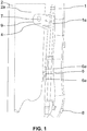
- the first tab 4 can be pierced with an oblong hole 7 for a passage of the clip 3 in its interior, visible at the figure 1 without the presence of the clip.
- the oblong hole 7 can extend in length parallel to the first chute 1, leaving a take-up play in its length for positioning the clip 3 in its interior. Ease of assembly is obtained, the clip 3 possibly having a positioning clearance in the oblong hole 7, taking into account the manufacturing disparities between different first chutes 1 or different second chutes 2.
- the portion 2a of or secured to the second chute 2 can be a portion of a degassing capacity 2a integrated into the second chute 2.
- the degassing capacity 2a of the second chute 2 can undergo a shape adaptation with a part of the degassing capacity 2a locally crushed to form a flat receiving surface 9 for the passage of the clip 3, this receiving surface being visible at the figure 1 being covered by the first tab 4.
- the portion 2a can also be made integral with the second chute 2 in a removable manner.
- the chutes 1, 2 are advantageously cylindrical and do not have a thick wall. It is therefore preferred to make the connection between the chutes 1, 2 by at least one element 1a, 2a fixed to one of the two chutes 1, 2.
- the degassing capacity 1a of one 1 of the two chutes 1, 2 with the degassing capacity 2a of the other chute 2 in order to have more room to make a connection, of a on the one hand, by a clip 3 and, on the other hand, by a second tab 5 carried by the degassing capacity 2a of the second chute 2 inserting into at least one groove 6 as a housing carried by the degassing capacity 1a of the first chute 1.
- the pointed head 3a at each end of the clip 3 is a conical or slotted head.
- the split head 3a allows a reduction in the size of the head when it is introduced into a passage provided in the first tab 4 carried by the first chute 1 or a portion 1a secured to the first chute 1 and in a portion 2a of or secured to the second chute 2.
- the end portions of the pointed head 3a move away from each other after having passed through the first tab 4 or the portion 2a of or secured to the second chute 2.
- the second tab 5 secured to the second chute 2 or to a portion 2a secured to the second chute 2 can be inserted between and under two tabs 6a extending at a distance from the periphery of the first chute 1 or a portion 1a secured at the first chute 1.
- a groove 6, visible at the figure 5 can be present under each of the two tabs 6a.
- Each of the two tabs 6a covers a portion of a longitudinal edge of the second lug 5. The securing of the second lug 5 to the second chute or to a portion 2a of the second chute can be obtained by welding.
- the two tabs 6a can be opened at their free end for insertion of the opposite longitudinal edges of the second tab 5 under a respective tab 6a.
- the distance spacing each of the tabs 6a from the periphery of the first chute 1 or of the portion 1a secured to the first chute 1 may correspond to a thickness of the second tab 5 with the addition of a clearance just sufficient for insertion of the second. tab 5 under each of the tabs 6a so that the longitudinal edges of the second tab 5 are retained by friction under a respective tab 6a.
- This connection with two tabs 6a and a second tab 5 is similar to a sliding connection which may have a slight swiveling possible to take into account the dispersions in the course of the first chute 1.
- the portion 1a of or secured to the first chute 1 carrying the tabs 6a can be a degassing capacity 1a secured to the first chute 1.
- This degassing capacity 1a can be secured by latching means 8 removable from the first chute 1, the latching means being visible from the figure 1 .
- the first chute 1 may be the liquid agent chute and the second chute 2 may be the fuel chute 2.
- the two chutes 1, 2 may be cylindrical in shape, the fuel chute 2 having a larger diameter than the chute. liquid agent.
- the degassing capacity 2a of the fuel chute 2 can be of larger dimension than the degassing capacity 1a of the liquid agent chute 1.
- the degassing capacity 2a of the fuel spout 2 can be integral with the fuel spout 2 by being obtained by blowing while the degassing capacity 1a of the liquid agent spout 1 can be attached to the spout.
- liquid agent by latching means 8 for example of the open ring type partially surrounding the liquid agent chute, the ends of the open ring moving apart when the ring is inserted around the wall of the liquid agent chute 1 then the broken ring being held by elastic return against the wall of the liquid agent chute 1.
- the invention also relates to a system formed of a fuel supply device and a liquid agent supply device in a motor vehicle, each device comprising a tank supplied by a chute.
- each device comprising a tank supplied by a chute.
- the two chutes 1, 2 are joined together and form an assembly as described above.
- the system may include a degassing capacity 1a, 2a for each of the supply devices, the degassing capacities being integral with or integrally with their respective chute 1, 2.
- the connection between the two chutes 1, 2 can be made between the respective degassing capacities 1a, 2a.
- the liquid agent supply device is a reducing agent supply device for selective catalytic reduction of nitrogen oxides discharged from the heat engine via the exhaust line.
- the reducing agent supply device supplies a reducing agent injector into the exhaust line.
- the reducing agent which preferably turns into ammonia effects the reduction of nitrogen oxides in a catalytic reduction catalyst disposed downstream of the injector in the exhaust line with reference to the path of the exhaust gases.
Landscapes
- Engineering & Computer Science (AREA)
- Life Sciences & Earth Sciences (AREA)
- Sustainable Development (AREA)
- Sustainable Energy (AREA)
- Chemical & Material Sciences (AREA)
- Combustion & Propulsion (AREA)
- Transportation (AREA)
- Mechanical Engineering (AREA)
- Cooling, Air Intake And Gas Exhaust, And Fuel Tank Arrangements In Propulsion Units (AREA)
Description
L'invention porte sur un ensemble d'une première goulotte et d'une deuxième goulotte solidarisées ensemble. Ces deux goulottes alimentent deux réservoirs de fluides consommables pour véhicule automobile, avec un premier réservoir équipé de la première goulotte de remplissage et un deuxième réservoir équipé de la deuxième goulotte de remplissage.The invention relates to an assembly of a first chute and a second chute secured together. These two chutes supply two reservoirs of consumable fluids for a motor vehicle, with a first reservoir fitted with the first filler neck and a second reservoir fitted with the second filler neck.
Chacune des goulottes est en connexion fluidique avec son réservoir respectif et les goulottes de carburant et d'agent liquide débouchent dans une même zone de remplissage par des ouvertures formant têtes de remplissage, la deuxième goulotte étant fixée au moins provisoirement à la première goulotte dans ou au voisinage de la zone de remplissage par une pièce de solidarisation.Each of the chutes is in fluid connection with its respective tank and the fuel and liquid agent chutes open into the same filling zone through openings forming filling heads, the second chute being fixed at least temporarily to the first chute in or in the vicinity of the filling zone by a securing part.
En particulier, mais sans que cela soit limitatif, le premier réservoir de fluide peut être un réservoir d'agent réducteur pour un système de réduction catalytique sélective aussi dénommé système RCS, dénomination qui pourra être utilisée dans ce qui suit pour le désigner de même que pour désigner ses parties constitutives comme réservoir RCS pour le réservoir d'agent réducteur. Le deuxième réservoir peut être un réservoir de carburant. Cependant, dans le domaine automobile, les goulottes selon la présente invention, peuvent alimenter tout autre type de réservoir contenant un fluide.In particular, but without this being limiting, the first fluid reservoir may be a reservoir of reducing agent for a selective catalytic reduction system also known as the SCR system, a name which may be used in what follows to denote it as well as to designate its constituent parts as RCS reservoir for the reducing agent reservoir. The second tank can be a fuel tank. However, in the automotive field, the chutes according to the present invention can supply any other type of reservoir containing a fluid.
Donc, dans ce qui va suivre, il va être pris l'exemple d'un réservoir RCS pour décrire la présente invention. Ceci n'est pas limitatif et la présente invention peut concerner un ensemble de deux réservoirs solidarisés de n'importe quel fluide.Therefore, in what follows, the example of an RCS tank will be taken to describe the present invention. This is not limiting and the present invention may relate to an assembly of two reservoirs secured to any fluid.
Par exemple, dans le cas non limitatif d'un réservoir d'agent réducteur RCS, il a été développé des goulottes de remplissage qui vont se loger par une petite trappe située sur la façade latérale du véhicule, ainsi que des réservoirs RCS situés en partie basse du soubassement du véhicule. Le réservoir RCS se trouve à proximité du réservoir de carburant mais surtout les entrées de leurs goulottes sont reçues dans une même trappe ou dans des trappes voisines. Comme les normes de dépollution deviennent de plus en plus strictes, le réservoir RCS est destiné à être rempli de plus en plus fréquemment.For example, in the non-limiting case of an RCS reducing agent tank, filler chutes have been developed which will be housed by a small hatch located on the side facade of the vehicle, as well as RCS tanks located in part. bottom of the vehicle's underbody. The RCS tank is located near the fuel tank but above all the inlets of their chutes are received in the same hatch or in neighboring hatches. As pollution control standards become more and more strict, the RCS tank is intended to be filled more and more frequently.
En prenant toujours comme exemple un réservoir RCS, la plupart des véhicules Diesel fabriqués actuellement vont comporter au moins un réservoir RCS. La ou les goulottes ou tubulures se raccordant au réservoir, et au moins la goulotte de remplissage, peuvent être monoblocs avec le réservoir. Alternativement, elles peuvent être fabriquées indépendamment du réservoir et sont rapportées au réservoir ultérieurement, par une opération connue sous le terme de manchonnage.Always taking an RCS tank as an example, most diesel vehicles currently manufactured will include at least one RCS tank. The chutes or pipes connecting to the reservoir, and at least the filling chute, can be integral with the reservoir. Alternatively, they can be manufactured independently of the reservoir and are attached to the reservoir subsequently, by an operation known by the term sleeving.
Le réservoir RCS ainsi équipé est ensuite monté sur le véhicule, en usine terminale, par une opération dite de coiffage, consistant à déposer le réservoir et ses tubulures sur une platine, appelée également luge, disposée sous le soubassement du véhicule, puis à monter l'ensemble sur le véhicule. C'est le cas aussi du réservoir de carburant. Lors de l'opération de préparation sur luge, la tubulure RCS peut être montée encliquetée sur le réservoir RCS. Il en va de même pour le réservoir de carburant.The RCS tank thus equipped is then mounted on the vehicle, at the terminal plant, by a so-called capping operation, consisting in placing the tank and its pipes on a plate, also called a sled, placed under the base of the vehicle, then in mounting the tank. 'together on the vehicle. This is also the case with the fuel tank. During the sledge preparation operation, the RCS tubing can be snapped onto the RCS tank. The same goes for the fuel tank.
Par exemple, pour un véhicule de tourisme, le réservoir RCS contenant l'agent réducteur peut avoir une capacité de 10 à 20 litres, alors que le réservoir de carburant a au moins une capacité deux fois plus grande. Les goulottes de remplissage sont dimensionnées également en conséquence. Comme précédemment mentionné, il est fréquemment prévu d'implanter les réservoirs de carburant et RCS dans le véhicule de façon à ce que leurs goulottes de remplissage respectives débouchent dans la même zone, au niveau de la trappe de remplissage du véhicule, de façon à n'avoir qu'une seule trappe de remplissage, aisément accessible, pour les deux types de fluide.For example, for a passenger vehicle, the RCS tank containing the reducing agent may have a capacity of 10 to 20 liters, while the fuel tank has at least twice the capacity. The filler necks are also dimensioned accordingly. As previously mentioned, it is frequently planned to install the fuel tanks and RCS in the vehicle so that their respective filler chutes open into the same area, at the level of the filler flap of the vehicle, so as to n '' have only one filler flap, easily accessible, for both types of fluid.
Dans cette configuration, il a été observé un risque accru de casse, ou à tout le moins d'affaissement, de la goulotte de remplissage du réservoir RCS lors de l'opération de coiffage simultané des deux réservoirs, du fait, notamment, de sa faible résistance du fait de son faible dimensionnement.In this configuration, an increased risk of breakage, or at the very least sagging, of the filling chute of the RCS tank was observed during the operation of simultaneous capping of the two tanks, due in particular to its low resistance due to its low dimensioning.
Il est connu de solidariser les deux goulottes ensemble en plus de la solidarisation sur leurs extrémités respectives formant têtes de remplissage. Ceci peut être fait par une patte d'interface avec une opération de vissage. Un positionnement de la patte d'interface est cependant difficile à obtenir et l'opération de vissage prend du temps et nécessite l'emploi d'un élément supplémentaire qu'est la vis. De plus, le vissage peut être déficient avec un pas de vis faussé, étant donné la faible accessibilité pour le monteur.It is known practice to secure the two chutes together in addition to the securing on their respective ends forming filling heads. This can be done by an interface tab with a screwing operation. Positioning of the interface tab is however difficult to obtain and the screwing operation takes time and requires the use of an additional element, which is the screw. In addition, the screwing can be deficient with a distorted screw thread, given the poor accessibility for the fitter.
Le document
Cette solidarisation concerne les ouvertures des goulottes formant têtes de remplissage et ne garantit pas le positionnement du reste des goulottes l'une par rapport à l'autre. C'est justement ce que recherche la présente invention en complément ou non avec une telle solidarisation des têtes de remplissage. De plus, des moyens d'encliquetage montrés dans ce document peuvent se détacher par vibrations lors du roulage du véhicule en désolidarisant les goulottes l'une de l'autreThis joining concerns the openings of the chutes forming filling heads and does not guarantee the positioning of the rest of the chutes with respect to one another. This is precisely what the present invention seeks, whether or not in addition to such joining of the filling heads. In addition, the latching means shown in this document can be detached by vibrations during the rolling of the vehicle by separating the chutes from one another.
Par conséquent, le problème à la base de l'invention est, dans un véhicule automobile, pour deux goulottes respectivement de carburant et d'agent liquide s'étendant à proximité l'une de l'autre de solidariser les deux goulottes à distance de leur ouverture respective servant de tête de remplissage, la solidarisation devant être facile à mettre en œuvre et résistante en position lors du roulage du véhicule.Consequently, the problem at the basis of the invention is, in a motor vehicle, for two chutes respectively of fuel and of liquid agent extending close to one another to secure the two chutes at a distance of their respective opening serving as a filling head, the connection having to be easy to implement and resistant in position when the vehicle is moving.
Pour atteindre cet objectif, il est prévu selon l'invention un ensemble d'une goulotte de carburant et d'une goulotte d'un agent liquide, les goulottes s'étendant au moins partiellement parallèlement l'une à l'autre à partir d'une ouverture respective de remplissage, l'ensemble étant muni de moyens de solidarisation des deux goulottes entre elles, de sorte que, à distance des ouvertures de remplissage, les moyens de solidarisation sont réalisés, d'une part, par une agrafe double traversant une première patte portée par une portion d'une ou solidarisée à une première goulotte parmi les goulottes de carburant et d'agent liquide et une portion d'une ou solidarisée à une deuxième goulotte parmi les goulottes de carburant et d'agent liquide et, d'autre part, par une deuxième patte solidarisée à une portion de ou solidarisée à la deuxième goulotte pénétrant dans au moins une rainure portée par la périphérie d'une portion de ou solidarisée à la première goulotte, les première et deuxième pattes étant espacées l'une de l'autre.To achieve this objective, there is provided according to the invention an assembly of a fuel chute and a chute of a liquid agent, the chutes extending at least partially parallel to each other from 'a respective filling opening, the assembly being provided with means for securing the two chutes between them, so that, at a distance from the filling openings, the securing means are made, on the one hand, by a double through clip a first tab carried by a portion of one or secured to a first chute among the fuel and liquid agent chutes and a portion of or secured to a second chute among the fuel and liquid agent chutes and, on the other hand, by a second tab secured to a portion of or secured to the second chute penetrating into at least one groove carried by the periphery of a portion of or secured to the first chute, the first and second tab es being spaced from each other.
L'expression « la portion de ou solidarisée à une goulotte » signifie que la portion peut être une portion de la goulotte ou une portion solidarisée à la goulotte, par exemple une capacité de dégazage solidarisée à une goulotte respective.The expression "the portion of or integral with a chute" means that the portion may be a portion of the chute or a portion secured to the chute, for example a degassing capacity secured to a respective chute.
Les première et deuxième pattes sont espacées. Il s'ensuit que la portion de ou solidarisée à la deuxième goulotte recevant l'agrafe double et la portion de ou solidarisée à la deuxième goulotte portant la deuxième patte peuvent être les mêmes si on considère la portion comme un élément dans sa globalité, par exemple une capacité de dégazage solidarisée à la deuxième goulotte, mais l'agrafage et le support de la deuxième patte se font à des endroits différents de l'élément, par exemple la capacité de dégazage.The first and second legs are spaced apart. It follows that the portion of or secured to the second chute receiving the double clip and the portion of or secured to the second chute carrying the second tab may be the same if we consider the portion as an element in its entirety, for example a degassing capacity secured to the second chute, but the stapling and the support of the second tab are made at different places of the element, for example the degassing capacity.
L'effet technique est d'obtenir une solidarisation facilitée et résistante une fois effectuée entre les deux goulottes. Cette solidarisation n'est pas équivalente à la solidarisation par encliquetage réunissant les deux ouvertures de remplissage des deux goulottes mais peut venir en complément de cette solidarisation.The technical effect is to obtain an easier and resistant connection once made between the two chutes. This securing is not equivalent to securing by snap-fastening bringing together the two filling openings of the two chutes but can complement this securing.
La solidarisation selon la présente invention se fait à distance des ouvertures de remplissage par deux moyens de solidarisation différents et espacés l'un de l'autre. Le premier moyen de solidarisation est effectué par une agrafe double traversant une première patte portée par une portion d'une ou solidarisée à une première goulotte parmi les goulottes de carburant et d'agent liquide et une portion d'une ou solidarisée à une deuxième goulotte. En effet, la portion peut être une portion de la première goulotte ou une portion d'un élément solidarisé à la première goulotte, par exemple une capacité de dégazage de la première goulotte, ce qui n'est pas limitatif.The joining according to the present invention takes place at a distance from the filling openings by two different joining means spaced apart from one another. The first securing means is effected by a double clip passing through a first lug carried by a portion of one or secured to a first chute among the fuel and liquid agent channels and a portion of one or secured to a second chute . Indeed, the portion may be a portion of the first chute or a portion of an element secured to the first chute, for example a degassing capacity of the first chute, which is not limiting.
Le deuxième moyen de solidarisation est une deuxième patte solidarisée à une portion de ou solidarisée à la deuxième goulotte pénétrant dans au moins une rainure portée par la périphérie d'une portion de ou solidarisée à la première goulotte. Les portions des première et deuxième goulottes peuvent faire partie d'une goulotte respective ou être sur un élément solidarisé à la première ou la deuxième goulotte, par exemple une capacité de dégazage de la deuxième goulotte, ce qui n'est pas limitatif.The second securing means is a second tab secured to a portion of or secured to the second chute penetrating into at least one groove carried by the periphery of a portion of or secured to the first chute. The portions of the first and second chutes may form part of a respective chute or be on an element secured to the first or the second chute, for example a degassing capacity of the second chute, which is not limiting.
Les premier et deuxième moyens sont disposés de manière à renforcer la solidarisation dans des directions différentes entre les première et deuxième goulottes. Le premier moyen peut laisser un jeu limité pour la solidarisation des deux goulottes pour compenser des différences de forme entre, d'une part, premières goulottes et, d'autre part, deuxièmes goulottes.The first and second means are arranged so as to strengthen the connection in different directions between the first and second chutes. The first means can leave a limited play for the joining of the two chutes to compensate for differences in shape between, on the one hand, first chutes and, on the other hand, second chutes.
Le deuxième moyen avec solidarisation par insertion de la deuxième patte dans au moins une rainure permet de répondre aux dispersions de réalisation de la deuxième goulotte et des variations du parcours de la première goulotte.The second means with securing by insertion of the second lug in at least one groove makes it possible to respond to variations in the production of the second chute and to variations in the path of the first chute.
Le fait que la première patte soit solidarisée à la première goulotte et que la deuxième patte soit solidarisée à la deuxième goulotte répartit la solidarisation sur les deux goulottes en établissant une symétrie de solidarisation entre premier et deuxième moyens de solidarisation.The fact that the first tab is secured to the first chute and that the second tab is secured to the second chute distributes the attachment over the two chutes by establishing a symmetry of securing between first and second securing means.
La présente invention permet un gain d'un point de vissage par rapport à l'état de la technique. Ceci permet une simplification de l'emboutissage du passage de roue avec un gain d'un insert étanche soudé. Un tel ensemble peut être monté en zone de préparation mécanique sur une luge. Ceci permet une désolidarisation aisée puis un remontage facile de la solidarisation sans outil en service après-vente.The present invention allows a gain of a tightening point compared to the state of the art. This simplifies the stamping of the wheel arch with the benefit of a welded sealed insert. Such an assembly can be mounted in a mechanical preparation area on a sled. This allows easy separation and then easy reassembly of the connection without tools in after-sales service.
La solidarisation est obtenue relativement rapidement, d'une part, par passage de l'agrafe dans la première patte et dans une portion de ou solidarisée à la deuxième goulotte et, d'autre part, par insertion de la deuxième patte dans au moins une rainure portée par une portion de ou solidarisée à la première goulotte.The connection is obtained relatively quickly, on the one hand, by passing the clip through the first tab and in a portion of or secured to the second chute and, on the other hand, by inserting the second tab into at least one groove carried by a portion of or secured to the first chute.
Avantageusement, l'agrafe est de forme allongée en comprenant à chacune de deux extrémités opposées une tête pointue suivie par une collerette plus intérieure à l'agrafe que la tête pointue associée, un espacement étant prévu entre chaque collerette et la tête pointue associée et correspondant, à une extrémité de l'agrafe, à une épaisseur de la première patte et, à l'autre extrémité de l'agrafe, à l'épaisseur de la portion de ou solidarisée à la deuxième goulotte, la collerette et la tête pointue associée enserrant entre elles respectivement la première patte ou la portion de ou solidarisée à la deuxième goulotte. Chacune des collerettes s'appliquent contre la pièce que la collerette enserre avec la tête pointue associée. Une possibilité de déplacement de l'agrafe perpendiculairement au trou de passage de l'agrafe est de ce fait très limité.Advantageously, the clip is of elongated shape comprising at each of two opposite ends a pointed head followed by a flange more inside the clip than the associated pointed head, a spacing being provided between each flange and the associated and corresponding pointed head. , at one end of the clip, to a thickness of the first tab and, at the other end of the clip, to the thickness of the portion of or secured to the second chute, the collar and the associated pointed head enclosing between them respectively the first tab or the portion of or secured to the second chute. Each of the flanges is applied against the part that the flange encloses with the associated pointed head. A possibility of displacement of the staple perpendicular to the passage hole of the staple is therefore very limited.
Avantageusement, la première patte est percée d'un trou oblong pour un passage de l'agrafe en son intérieur, le trou oblong s'étendant en longueur parallèlement à la première goulotte en laissant un jeu de rattrapage dans sa longueur pour un positionnement de l'agrafe en son intérieur. Le trou oblong confère une possibilité de réglage dans sa longueur.Advantageously, the first tab is pierced with an oblong hole for a passage of the clip in its interior, the oblong hole extending in length parallel to the first chute leaving a clearance play in its length for a positioning of the staple inside. The oblong hole gives the possibility of adjustment in its length.
Avantageusement, la portion de ou solidarisée à la deuxième goulotte est une portion d'une capacité de dégazage intégrée à la deuxième goulotte. La capacité de dégazage est avantageusement d'un seul tenant avec la deuxième goulotte en étant obtenue par soufflage.Advantageously, the portion of or secured to the second chute is a portion of a degassing capacity integrated into the second chute. The degassing capacity is advantageously in one piece with the second chute, being obtained by blowing.
Avantageusement, la tête pointue est une tête fendue conique ou à pans. Les deux parties de la tête fendue peuvent se rétracter l'une vers l'autre lors du passage dans le trou oblong puis s'écarter l'une de l'autre par rappel élastique à la sortie du trou oblong.Advantageously, the pointed head is a conical or slotted head. The two parts of the split head can retract towards each other when passing through the oblong hole and then move away from each other by elastic return at the exit of the oblong hole.
Avantageusement, la deuxième patte solidarisée à la deuxième goulotte est insérée entre et sous deux languettes s'étendant à distance de la périphérie de la portion de ou solidarisée à la première goulotte en étant ouvertes à leur extrémité libre pour une insertion des bords longitudinaux opposés de la deuxième patte sous une languette respective, la distance des languettes de la périphérie de la première goulotte correspondant à une épaisseur de la deuxième patte avec ajout d'un jeu juste suffisant pour une insertion de la deuxième patte dans la rainure présente sous chacune des languettes.Advantageously, the second tab secured to the second chute is inserted between and under two tabs extending at a distance from the periphery of the portion of or secured to the first chute by being open at their free end for insertion of the opposite longitudinal edges of the second tab under a respective tab, the distance of the tabs from the periphery of the first chute corresponding to a thickness of the second tab with the addition of a clearance just sufficient for insertion of the second tab in the groove present under each of the tabs .
Avantageusement, la portion de ou solidarisée à la première goulotte portant les languettes est une capacité de dégazage solidarisée à la première goulotte par des moyens d'encliquetage amovibles.Advantageously, the portion of or secured to the first chute carrying the tongues is a degassing capacity secured to the first chute by removable latching means.
Dans ce mode de réalisation contrairement de la capacité de dégazage intégrée à la deuxième goulotte qui peut être la goulotte de carburant, la capacité de dégazage de la première goulotte qui peut être la goulotte d'agent liquide est solidarisée de manière amovible avec la première goulotte. La capacité de dégazage de la deuxième goulotte peut être de dimension plus importante que la capacité de dégazage de la première goulotte, d'où une nécessité du renforcement de la solidarisation entre la deuxième goulotte et sa capacité de dégazage associée.In this embodiment, unlike the degassing capacity integrated into the second chute which may be the fuel chute, the degassing capacity of the first chute which may be the liquid agent chute is removably secured with the first chute. . The degassing capacity of the second chute can be larger than the degassing capacity of the first chute, hence the need to strengthen the connection between the second chute and its associated degassing capacity.
Avantageusement, la première goulotte est la goulotte d'agent liquide et la deuxième goulotte est la goulotte de carburant.Advantageously, the first chute is the liquid agent chute and the second chute is the fuel chute.
L'invention concerne un système formé d'un dispositif d'alimentation en carburant et d'un dispositif d'alimentation en agent liquide dans un véhicule automobile, chaque dispositif comprenant un réservoir alimenté par une goulotte, caractérisé en ce que les deux goulottes sont solidarisées entre elles et forment un tel ensemble. Le système est ainsi compact et capable de résister aux vibrations lors du roulage du véhicule automobile ou aussi un maintien en position des deux goulottes l'une par rapport à l'autre lors du montage.The invention relates to a system formed of a fuel supply device and a liquid agent supply device in a motor vehicle, each device comprising a tank supplied by a chute, characterized in that the two chutes are joined together and form such a whole. The system is thus compact and capable of withstanding vibrations when the motor vehicle is running or also maintaining the two chutes in position relative to each other during assembly.
Avantageusement, le dispositif d'alimentation en agent liquide est un dispositif d'alimentation en agent réducteur pour une réduction catalytique sélective.Advantageously, the device for supplying liquid agent is a device for supplying reducing agent for selective catalytic reduction.
D'autres caractéristiques, buts et avantages de la présente invention apparaîtront à la lecture de la description détaillée qui va suivre et au regard des dessins annexés donnés à titre d'exemples non limitatifs et sur lesquels :
- la
figure 1 est une représentation schématique d'une solidarisation en deux points entre une goulotte de carburant et une goulotte d'agent liquide formant un ensemble selon la présente invention, - la
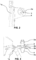
figure 2 est une représentation schématique d'une vue en perspective d'une capacité de dégazage solidarisée à la première goulotte étant une goulotte d'agent liquide portant une première patte de solidarisation avec la deuxième goulotte étant une goulotte de carburant par agrafage réalisant le premier point de solidarisation selon la présente invention, - la
figure 3 est une représentation schématique d'une vue en perspective d'une portion de la capacité de dégazage montrée à lafigure 2 sous un autre angle de vue et en étant agrandie avec une agrafe positionnée dans un trou oblong pratiqué sur la première patte, - la
figure 4 est une représentation schématique d'une vue en perspective d'une capacité de dégazage solidarisée à la deuxième goulotte étant une goulotte de carburant et d'une capacité de dégazage solidarisée à la première goulotte étant une goulotte d'agent liquide, la capacité de dégazage de la deuxième goulotte portant une deuxième patte de solidarisation insérée dans au moins une rainure portée par la capacité de dégazage solidarisée à la première goulotte, la deuxième patte et ladite au moins une rainure réalisant le deuxième point de solidarisation selon la présente invention, - la
figure 5 est une représentation schématique d'une vue en perspective sous un autre angle de vue et agrandie par rapport à lafigure 4 de la solidarisation entre deuxième patte et ladite au moins une rainure.
- the
figure 1 is a schematic representation of a two-point connection between a fuel chute and a liquid agent chute forming an assembly according to the present invention, - the
figure 2 is a schematic representation of a perspective view of a degassing capacity secured to the first chute being a liquid agent chute carrying a first attachment tab with the second chute being a fuel chute by stapling making the first point of joining according to the present invention, - the
figure 3 is a schematic representation of a perspective view of a portion of the degassing capacity shown infigure 2 from another angle of view and being enlarged with a clip positioned in an oblong hole made on the first leg, - the
figure 4 is a schematic representation of a perspective view of a degassing capacity secured to the second chute being a fuel chute and of a degassing capacity secured to the first chute being a liquid agent chute, the degassing capacity of the second chute carrying a second securing lug inserted in at least one groove carried by the degassing capacity secured to the first chute, the second lug and said at least one groove forming the second securing point according to the present invention, - the
figure 5 is a schematic representation of a perspective view from another viewing angle and enlarged with respect to thefigure 4 of the connection between the second tab and said at least one groove.
Il est à garder à l'esprit que les figures sont données à titre d'exemples et ne sont pas limitatives de l'invention. Elles constituent des représentations schématiques de principe destinées à faciliter la compréhension de l'invention et ne sont pas nécessairement à l'échelle des applications pratiques. En particulier, les dimensions des différents éléments illustrés ne sont pas représentatives de la réalité.It should be kept in mind that the figures are given by way of example and are not limiting of the invention. They constitute schematic representations of principle intended to facilitate understanding of the invention and are not necessarily on the scale of practical applications. In particular, the dimensions of the various elements illustrated are not representative of reality.
Dans ce qui va suivre, il est fait référence à toutes les figures prises en combinaison. Quand il est fait référence à une ou des figures spécifiques, ces figures sont à prendre en combinaison avec les autres figures pour la reconnaissance des références numériques désignées.In what follows, reference is made to all the figures taken in combination. When reference is made to one or more specific figures, these figures are to be taken in combination with the other figures for the recognition of the designated reference numerals.
En se référant à toutes les figures, la présente invention concerne un ensemble d'une goulotte de carburant 2 et d'une goulotte d'un agent liquide 1. Chaque goulotte peut former une unité déjà montée avec un réservoir respectif ou un réservoir respectif peut être postérieurement solidarisé avec chaque goulotte, les réservoirs n'étant pas montrés aux figures.Referring to all the figures, the present invention relates to an assembly of a fuel chute 2 and a chute of a
Les goulottes 1, 2 s'étendent sensiblement parallèlement l'une à l'autre au moins sur une portion de leur longueur à partir d'une ouverture respective de remplissage ou tête de remplissage. Il est possible que les têtes de remplissage des deux goulottes 1, 2 soient solidarisées ensemble, avantageusement par des moyens d'encliquetage comme deux anneaux ouverts solidarisés ensemble en entourant partiellement une tête de remplissage respective, mais ceci n'est pas forcément nécessaire dans le cadre de la présente invention.The
L'ensemble est muni de moyens de solidarisation 3 à 6, 6a des deux goulottes 1, 2 entre elles pour maintenir les goulottes 1, 2 sur au moins une partie de leur longueur l'une par rapport à l'autre. Selon l'invention, à distance des ouvertures de remplissage donc en étant différents de possibles moyens de solidarisation des ouvertures de remplissage, les moyens de solidarisation 3 à 6, 6a sont réalisés, premièrement, par une agrafe 3 double traversant une première patte 4 portée par une portion 1a d'une ou solidarisée à une première goulotte 1 parmi les goulottes de carburant 2 et d'agent liquide 1 et une portion 2a d'une ou solidarisée à une deuxième goulotte 2 parmi les goulottes de carburant 2 et d'agent liquide 1.The assembly is provided with
Les moyens de solidarisation 3 à 6, 6a sont aussi réalisés, deuxièmement, par une deuxième patte 5 solidarisée à une portion 2a de ou solidarisée à la deuxième goulotte 2 pénétrant dans au moins une rainure 6 portée par la périphérie d'une portion 1a de ou solidarisée à la première goulotte 1.The securing means 3 to 6, 6a are also produced, secondly, by a
Il y a donc deux points de solidarisation entre les deux goulottes 1, 2, les points de fixation étant espacés l'un de l'autre pour maintenir sur le plus de longueur possible les deux goulottes 1, 2 l'une par rapport à l'autre, ceci avantageusement parallèlement l'une à l'autre. Comme précédemment mentionné dans l'exposé de l'invention le mot portion désigne un élément dans son entité qui est solidarisé à une goulotte respective. Les deux points de solidarisation espacés se font à différents endroits de la portion, c'est-à-dire de l'élément solidarisé à une goulotte respective.There are therefore two securing points between the two
Les moyens de solidarisation 3 à 6, 6a peuvent directement solidariser les goulottes 1, 2 entre elles par des portions de goulotte. En alternative, la solidarisation peut concerner un élément associé à la goulotte. Par exemple, cet élément peut être une capacité de dégazage faisant partie ou non de la goulotte en étant soit d'un seul tenant avec une des deux goulottes 1, 2, comme par exemple une capacité de dégazage d'une goulotte de carburant 2 ou étant solidarisé, avantageusement de manière amovible, avec une des deux goulottes 1, 2.The securing means 3 to 6, 6a can directly secure the
Ceci peut être le cas d'une capacité de dégazage de la goulotte d'agent liquide qui présente une capacité moins grande que la capacité de dégazage d'une goulotte de carburant 2 et qui peut être solidarisé par des moyens d'encliquetage 8 avec la goulotte d'agent liquide, ces moyens étant visibles à la
En se référant plus particulièrement aux
Dans ce cas, un espacement peut être prévu entre chaque collerette 3b et la tête pointue 3a associée. Cet espacement peut correspondre, à une extrémité de l'agrafe 3, à une épaisseur de la première patte 4 et, à l'autre extrémité de l'agrafe 3, à l'épaisseur de la portion 2a de ou solidarisée à la deuxième goulotte 2. La collerette 3b et la tête pointue 3a associée peuvent enserrer entre elles respectivement la première patte 4 ou la portion 2a de ou solidarisée à la deuxième goulotte 2.In this case, a spacing can be provided between each
L'agrafe 3 est un moyen de solidarisation aussi efficace qu'une vis mais est plus facile à monter. Les deux collerettes 3b, effectuant un blocage en directions opposées l'une de l'autre, empêchent un mouvement de sortie de l'agrafe 3 de la première partie à une de ses extrémités et de la portion 2a de ou solidarisée à la deuxième goulotte 2 à son autre extrémité.The
La première patte 4 peut être percée d'un trou oblong 7 pour un passage de l'agrafe 3 en son intérieur, visible à la
Comme précédemment mentionné, la portion 2a de ou solidarisée à la deuxième goulotte 2 peut être une portion d'une capacité de dégazage 2a intégrée à la deuxième goulotte 2. La capacité de dégazage 2a de la deuxième goulotte 2 peut subir une adaptation de forme avec une partie de la capacité de dégazage 2a localement écrasée pour former une surface de réception plane 9 pour le passage de l'agrafe 3, cette surface de réception étant visible à la
La portion 2a peut aussi être solidarisée avec la deuxième goulotte 2 de manière amovible. Les goulottes 1, 2 sont avantageusement cylindriques et ne présentent pas une paroi épaisse. Il est donc préféré réaliser la solidarisation entre les goulottes 1, 2 par au moins un élément 1a, 2a solidarisé à une des deux goulottes 1, 2.The
Dans ce contexte, il est préféré solidariser la capacité de dégazage 1a d'une 1 des deux goulottes 1, 2 avec la capacité de dégazage 2a de l'autre goulotte 2 afin d'avoir plus de place pour réaliser une solidarisation, d'une part, par une agrafe 3 et, d'autre part, par une deuxième patte 5 portée par la capacité de dégazage 2a de la deuxième goulotte 2 s'insérant dans au moins une rainure 6 en tant que logement porté par la capacité de dégazage 1a de la première goulotte 1.In this context, it is preferred to join the
Pour l'agrafe 3, la tête pointue 3a à chacune des extrémités de l'agrafe 3 est une tête fendue conique ou à pans. La tête fendue 3a permet une diminution de la dimension de la tête lors de son introduction dans un passage prévu dans la première patte 4 portée par la première goulotte 1 ou une portion 1a solidarisée avec la première goulotte 1 et dans une portion 2a de ou solidarisée à la deuxième goulotte 2. Les portions d'extrémité de la tête pointue 3a s'écartent les unes des autres après avoir traversé la première patte 4 ou la portion 2a de ou solidarisée à la deuxième goulotte 2.For the
Pour le deuxième point de fixation, en se référant plus particulièrement aux
Une rainure 6, visible à la
Les deux languettes 6a peuvent être ouvertes à leur extrémité libre pour une insertion des bords longitudinaux opposés de la deuxième patte 5 sous une languette 6a respective. La distance espaçant chacune des languettes 6a de la périphérie de la première goulotte 1 ou de la portion 1a solidarisée à la première goulotte 1 peut correspondre à une épaisseur de la deuxième patte 5 avec ajout d'un jeu juste suffisant pour une insertion de la deuxième patte 5 sous chacune des languettes 6a afin que les bords longitudinaux de la deuxième patte 5 soient retenus par friction sous une languette 6a respective.The two
Cette solidarisation à deux languettes 6a et une deuxième patte 5 s'apparente à une liaison glissière qui peut présenter un léger rotulage possible pour la prise en compte des dispersions de parcours de la première goulotte 1.This connection with two
Dans un mode de réalisation préférentielle de la présente invention, la portion 1a de ou solidarisée à la première goulotte 1 portant les languettes 6a peut être une capacité de dégazage 1a solidarisée à la première goulotte 1. Cette capacité de dégazage 1a peut être solidarisée par des moyens d'encliquetage 8 amovibles à la première goulotte 1, les moyens d'encliquetage étant visibles à la
La première goulotte 1 peut être la goulotte d'agent liquide et la deuxième goulotte 2 peut être la goulotte de carburant 2. Les deux goulottes 1, 2 peuvent être de forme cylindrique, la goulotte de carburant 2 présentant un diamètre plus grand que la goulotte d'agent liquide. Quand des capacités de dégazage 1a, 2a sont présentes, la capacité de dégazage 2a de la goulotte de carburant 2 peut être de plus grande dimension que la capacité de dégazage 1a de la goulotte d'agent liquide 1.The
La capacité de dégazage 2a de la goulotte de carburant 2 peut être d'un seul tenant avec la goulotte de carburant 2 en étant obtenue par soufflage tandis que la capacité de dégazage 1a de la goulotte d'agent liquide 1 peut être fixée à la goulotte d'agent liquide par des moyens d'encliquetage 8, par exemple du type anneau ouvert entourant partiellement la goulotte d'agent liquide, les extrémités de l'anneau ouvert s'écartant lors de l'insertion de l'anneau autour de la paroi extérieure de la goulotte d'agent liquide 1 puis l'anneau brisé étant maintenu par rappel élastique contre la paroi de la goulotte d'agent liquide 1.The
L'invention concerne aussi un système formé d'un dispositif d'alimentation en carburant et d'un dispositif d'alimentation en agent liquide dans un véhicule automobile, chaque dispositif comprenant un réservoir alimenté par une goulotte. Dans ce système, les deux goulottes 1, 2 sont solidarisées entre elles et forment un ensemble tel que précédemment décrit.The invention also relates to a system formed of a fuel supply device and a liquid agent supply device in a motor vehicle, each device comprising a tank supplied by a chute. In this system, the two
Le système peut comprendre une capacité de dégazage 1a, 2a pour chacun des dispositifs d'alimentation, les capacités de dégazage étant solidarisées avec ou d'un seul tenant avec leur goulotte 1, 2 respective. La solidarisation entre les deux goulottes 1, 2 peut se faire entre les capacités de dégazage 1a, 2a respectives.The system may include a
Dans une application préférentielle, le dispositif d'alimentation en agent liquide est un dispositif d'alimentation en agent réducteur pour une réduction catalytique sélective des oxydes d'azote évacués du moteur thermique par la ligne d'échappement.In a preferred application, the liquid agent supply device is a reducing agent supply device for selective catalytic reduction of nitrogen oxides discharged from the heat engine via the exhaust line.
Le dispositif d'alimentation en agent réducteur alimente un injecteur d'agent réducteur dans la ligne d'échappement. L'agent réducteur qui de préférence se transforme en ammoniac effectue la réduction des oxydes d'azote dans un catalyseur de réduction catalytique disposé en aval de l'injecteur dans la ligne d'échappement en se référant au parcours des gaz d'échappement.The reducing agent supply device supplies a reducing agent injector into the exhaust line. The reducing agent which preferably turns into ammonia effects the reduction of nitrogen oxides in a catalytic reduction catalyst disposed downstream of the injector in the exhaust line with reference to the path of the exhaust gases.
L'invention n'est nullement limitée aux modes de réalisation décrits et illustrés qui n'ont été donnés qu'à titre d'exemples.The invention is in no way limited to the embodiments described and illustrated which have been given only by way of example.
Claims (10)
- Assembly of a fuel chute (2) and a liquid agent chute (1), the chutes (1, 2) extending at least partially parallel to each other from a respective filling opening, the assembly being provided with securing means (3 to 6, 6a) of the two chutes (1, 2) between them, so that, at a distance from the filling openings, the securing means (3 to 6, 6a) are produced, on the one hand, by a double clip (3) passing through a first tab (4) carried by a portion (1a) of one or secured to a first chute (1) among the fuel chutes (2) and liquid agent (1) and a portion (2a) of one or integral with a second chute (2) among the fuel (2) and liquid agent (1) chutes and, on the other hand, by a second tab (5) secured to a portion (2a) of or secured to the second chute (2) penetrating into at least one groove (6) carried by the periphery of a portion (1a) of or secured to the first chute (1), the first and second legs (4, 5) being spaced from each other.
- Assembly according to claim 1, wherein the clip (3) is elongated in shape comprising at each of two opposite ends a pointed head (3a) followed by a flange (3b) more interior to the clip (3) than the associated pointed head (3a), a spacing being provided between each flange (3b) and the associated pointed head (3a) and corresponding, at one end of the clip (3), to a thickness of the first tab (4) and, at the other end of the clip (3), to the thickness of the portion (2a) of or secured to the second chute (2), the collar (3b) and the associated pointed head (3a) clamping between they respectively the first tab (4) or the portion (2a) of or secured to the second chute (2).
- Assembly according to Claim 2, in which the first tab (4) is pierced with an oblong hole (7) for a passage of the clip (3) in its interior, the oblong hole (7) extending in parallel length to the first chute (1), leaving a take-up play in its length for positioning the clip (3) inside it.
- Assembly according to any one of the two preceding claims, in which the portion (2a) of or integral with the second chute (2) is a portion of a degassing capacity (2a) integrated in the second chute (2).
- Assembly according to any one of the three preceding claims, in which the pointed head (3a) is a tapered or slotted head.
- Assembly according to any one of the preceding claims, in which the second tab (5) secured to the portion (2a) of or secured to the second chute (2) is inserted between and under two tongues (6a) extending at a distance of the periphery of the portion (1a) of or secured to the first chute (1) by being open at their free end for insertion of the opposite longitudinal edges of the second tab (5) under a respective tongue (6a), the distance tongues (6a) of the periphery of the portion (1a) or secured to the first chute (1) corresponding to a thickness of the second leg (5) with the addition of just sufficient play for insertion of the second tab (5) in the groove (6) present under each of the tongues (6a).
- Assembly according to the preceding claim, in which the portion (1a) of or secured to the first chute (1) carrying the tabs (6a) is a degassing capacity (1a) secured to the first chute (1) by means of removable snap-locks (8).
- Assembly according to any preceding claim, wherein the first chute (1) is the liquid agent chute and the second chute (2) is the fuel chute (2).
- System formed of a fuel supply device and a liquid agent supply device in a motor vehicle, each device comprising a tank supplied by a chute (1, 2), characterized in that the two chutes (1, 2) are joined together and form an assembly according to any one of the preceding claims.
- System according to the preceding claim, in which the liquid agent supply device is a reducing agent supply device for selective catalytic reduction.
Applications Claiming Priority (2)
| Application Number | Priority Date | Filing Date | Title |
|---|---|---|---|
| FR1757787A FR3070326B1 (en) | 2017-08-22 | 2017-08-22 | ASSEMBLY OF A FUEL CHUTE AND A CHUTE OF A SOLIDARIZED LIQUID AGENT TOGETHER |
| PCT/FR2018/051829 WO2019038489A1 (en) | 2017-08-22 | 2018-07-18 | Assembly of a fuel tube and liquid agent tube fastened together |
Publications (2)
| Publication Number | Publication Date |
|---|---|
| EP3672822A1 EP3672822A1 (en) | 2020-07-01 |
| EP3672822B1 true EP3672822B1 (en) | 2021-07-14 |
Family
ID=60020160
Family Applications (1)
| Application Number | Title | Priority Date | Filing Date |
|---|---|---|---|
| EP18752586.0A Active EP3672822B1 (en) | 2017-08-22 | 2018-07-18 | Assembly of a fuel tube and liquid agent tube fastened together |
Country Status (4)
| Country | Link |
|---|---|
| EP (1) | EP3672822B1 (en) |
| FR (1) | FR3070326B1 (en) |
| MA (1) | MA49938B1 (en) |
| WO (1) | WO2019038489A1 (en) |
Families Citing this family (1)
| Publication number | Priority date | Publication date | Assignee | Title |
|---|---|---|---|---|
| DE102020126002A1 (en) | 2020-10-05 | 2022-04-07 | Röchling Automotive SE & Co. KG | Line system, filling arrangement with line system and method for producing a line system |
Family Cites Families (4)
| Publication number | Priority date | Publication date | Assignee | Title |
|---|---|---|---|---|
| DE4023094C2 (en) * | 1989-07-29 | 1996-12-12 | Volkswagen Ag | Plastic fuel tank for a motor vehicle |
| DE4014589C1 (en) * | 1990-05-07 | 1991-08-08 | Trw United-Carr Gmbh & Co Kg, 6753 Enkenbach-Alsenborn, De | |
| FR2983165B1 (en) * | 2011-11-30 | 2013-11-22 | Faurecia Interieur Ind | VEHICLE ELEMENT |
| FR3034052B1 (en) | 2015-03-27 | 2017-03-31 | Peugeot Citroen Automobiles Sa | CONSUMABLE FLUID TANK ASSEMBLY FOR MOTOR VEHICLE |
-
2017
- 2017-08-22 FR FR1757787A patent/FR3070326B1/en not_active Expired - Fee Related
-
2018
- 2018-07-18 WO PCT/FR2018/051829 patent/WO2019038489A1/en unknown
- 2018-07-18 MA MA49938A patent/MA49938B1/en unknown
- 2018-07-18 EP EP18752586.0A patent/EP3672822B1/en active Active
Also Published As
| Publication number | Publication date |
|---|---|
| MA49938B1 (en) | 2021-09-30 |
| WO2019038489A1 (en) | 2019-02-28 |
| EP3672822A1 (en) | 2020-07-01 |
| MA49938A (en) | 2021-03-31 |
| FR3070326B1 (en) | 2019-09-13 |
| FR3070326A1 (en) | 2019-03-01 |
Similar Documents
| Publication | Publication Date | Title |
|---|---|---|
| EP3274206B1 (en) | Assembly of tanks of consumable fluids for a motor vehicle | |
| CA2647145C (en) | Device for guiding an element into an orifice of a gas turbine combustion chamber wall | |
| FR2998629A1 (en) | FOLLOWING ROLL DEVICE OF A CAM | |
| FR2774738A1 (en) | PRESSURE SHOCK ABSORBER FOR A PRESSURE TANK | |
| EP3672822B1 (en) | Assembly of a fuel tube and liquid agent tube fastened together | |
| EP3609729B1 (en) | Assembly of two fluid tanks with secured pipes | |
| FR2761626A1 (en) | Assembly of sheet metal components by welding | |
| EP3814616B1 (en) | Guiding device in a combustion chamber | |
| EP0621153B1 (en) | Filler pipe for fuel tank, especially for motor vehicle | |
| WO2019155142A1 (en) | Assembly for supplying fuel or pollution control product to a motor vehicle | |
| FR2866419A1 (en) | Collector box for heat exchanger, has collar cooperating with body neck comprising male section arranged for being introduced in female section of collar, where sections temporarily maintain neck on box before and during brazing of neck | |
| EP2471152B1 (en) | Comb flange for high-voltage cables | |
| EP3807114B1 (en) | Tank provided with pipes to facilitate the packaging thereof | |
| EP3752381B1 (en) | Assembly comprising a stiffening support and a strap for a motor vehicle fuel tank | |
| EP2909468A1 (en) | Flange for fastening at least one injector to a cylinder head of a combustion engine | |
| WO2023285512A1 (en) | Device for attaching an element to a part of a motor vehicle | |
| EP3297867B1 (en) | Tank with integrated skirt | |
| EP2940363B1 (en) | Connection device between the opening of a fluid reservoir and a pipe | |
| FR3014484B1 (en) | THERMAL PROTECTION SCREEN FOR EXHAUST GAS OUTPUT DEVICE OF MOTOR VEHICLE | |
| WO2017144799A1 (en) | Element for supporting a part that is used to maintain components secured to a structural part of a motor vehicle | |
| FR2878296A1 (en) | Pollution control catalyst and internal combustion engine`s exhaust side clamping device, has conical screw with its axis parallel to orientation direction of pollution control catalyst, and spring wound around screw and connected to strap | |
| EP3610140A1 (en) | Fluid tank having an external pipe held by a clip | |
| FR3085632A1 (en) | CONNECTION DEVICE BETWEEN TUBING HEADS OF TANKS AND MOTOR VEHICLE EQUIPPED WITH SUCH A DEVICE | |
| FR3072663A3 (en) | DEVICE FOR INTRODUCING AN ADDITIVE PRODUCT IN A FUEL OR GAS-OIL FEEDING SYSTEM OF A MOTOR VEHICLE. | |
| WO2006045940A1 (en) | Device for treating exhaust gas for a motor vehicle, and corresponding vehicle |
Legal Events
| Date | Code | Title | Description |
|---|---|---|---|
| STAA | Information on the status of an ep patent application or granted ep patent |
Free format text: STATUS: UNKNOWN |
|
| STAA | Information on the status of an ep patent application or granted ep patent |
Free format text: STATUS: THE INTERNATIONAL PUBLICATION HAS BEEN MADE |
|
| PUAI | Public reference made under article 153(3) epc to a published international application that has entered the european phase |
Free format text: ORIGINAL CODE: 0009012 |
|
| STAA | Information on the status of an ep patent application or granted ep patent |
Free format text: STATUS: REQUEST FOR EXAMINATION WAS MADE |
|
| 17P | Request for examination filed |
Effective date: 20200115 |
|
| AK | Designated contracting states |
Kind code of ref document: A1 Designated state(s): AL AT BE BG CH CY CZ DE DK EE ES FI FR GB GR HR HU IE IS IT LI LT LU LV MC MK MT NL NO PL PT RO RS SE SI SK SM TR |
|
| AX | Request for extension of the european patent |
Extension state: BA ME |
|
| RAP1 | Party data changed (applicant data changed or rights of an application transferred) |
Owner name: PSA AUTOMOBILES SA |
|
| DAX | Request for extension of the european patent (deleted) | ||
| RAV | Requested validation state of the european patent: fee paid |
Extension state: MA Effective date: 20200115 |
|
| GRAP | Despatch of communication of intention to grant a patent |
Free format text: ORIGINAL CODE: EPIDOSNIGR1 |
|
| STAA | Information on the status of an ep patent application or granted ep patent |
Free format text: STATUS: GRANT OF PATENT IS INTENDED |
|
| INTG | Intention to grant announced |
Effective date: 20210302 |
|
| RIN1 | Information on inventor provided before grant (corrected) |
Inventor name: LE GUYADER, GAEL |
|
| GRAS | Grant fee paid |
Free format text: ORIGINAL CODE: EPIDOSNIGR3 |
|
| GRAA | (expected) grant |
Free format text: ORIGINAL CODE: 0009210 |
|
| STAA | Information on the status of an ep patent application or granted ep patent |
Free format text: STATUS: THE PATENT HAS BEEN GRANTED |
|
| AK | Designated contracting states |
Kind code of ref document: B1 Designated state(s): AL AT BE BG CH CY CZ DE DK EE ES FI FR GB GR HR HU IE IS IT LI LT LU LV MC MK MT NL NO PL PT RO RS SE SI SK SM TR |
|
| REG | Reference to a national code |
Ref country code: GB Ref legal event code: FG4D Free format text: NOT ENGLISH |
|
| REG | Reference to a national code |
Ref country code: DE Ref legal event code: R096 Ref document number: 602018020143 Country of ref document: DE |
|
| REG | Reference to a national code |
Ref country code: IE Ref legal event code: FG4D Free format text: LANGUAGE OF EP DOCUMENT: FRENCH |
|
| REG | Reference to a national code |
Ref country code: DE Ref legal event code: R084 Ref document number: 602018020143 Country of ref document: DE |
|
| REG | Reference to a national code |
Ref country code: AT Ref legal event code: REF Ref document number: 1410368 Country of ref document: AT Kind code of ref document: T Effective date: 20210815 |
|
| REG | Reference to a national code |
Ref country code: MA Ref legal event code: VAGR Ref document number: 49938 Country of ref document: MA Kind code of ref document: B1 |
|
| REG | Reference to a national code |
Ref country code: GB Ref legal event code: 746 Effective date: 20210910 |
|
| REG | Reference to a national code |
Ref country code: LT Ref legal event code: MG9D |
|
| REG | Reference to a national code |
Ref country code: NL Ref legal event code: MP Effective date: 20210714 |
|
| REG | Reference to a national code |
Ref country code: AT Ref legal event code: MK05 Ref document number: 1410368 Country of ref document: AT Kind code of ref document: T Effective date: 20210714 |
|
| PG25 | Lapsed in a contracting state [announced via postgrant information from national office to epo] |
Ref country code: SE Free format text: LAPSE BECAUSE OF FAILURE TO SUBMIT A TRANSLATION OF THE DESCRIPTION OR TO PAY THE FEE WITHIN THE PRESCRIBED TIME-LIMIT Effective date: 20210714 Ref country code: RS Free format text: LAPSE BECAUSE OF FAILURE TO SUBMIT A TRANSLATION OF THE DESCRIPTION OR TO PAY THE FEE WITHIN THE PRESCRIBED TIME-LIMIT Effective date: 20210714 Ref country code: HR Free format text: LAPSE BECAUSE OF FAILURE TO SUBMIT A TRANSLATION OF THE DESCRIPTION OR TO PAY THE FEE WITHIN THE PRESCRIBED TIME-LIMIT Effective date: 20210714 Ref country code: FI Free format text: LAPSE BECAUSE OF FAILURE TO SUBMIT A TRANSLATION OF THE DESCRIPTION OR TO PAY THE FEE WITHIN THE PRESCRIBED TIME-LIMIT Effective date: 20210714 Ref country code: ES Free format text: LAPSE BECAUSE OF FAILURE TO SUBMIT A TRANSLATION OF THE DESCRIPTION OR TO PAY THE FEE WITHIN THE PRESCRIBED TIME-LIMIT Effective date: 20210714 Ref country code: LT Free format text: LAPSE BECAUSE OF FAILURE TO SUBMIT A TRANSLATION OF THE DESCRIPTION OR TO PAY THE FEE WITHIN THE PRESCRIBED TIME-LIMIT Effective date: 20210714 Ref country code: AT Free format text: LAPSE BECAUSE OF FAILURE TO SUBMIT A TRANSLATION OF THE DESCRIPTION OR TO PAY THE FEE WITHIN THE PRESCRIBED TIME-LIMIT Effective date: 20210714 Ref country code: BG Free format text: LAPSE BECAUSE OF FAILURE TO SUBMIT A TRANSLATION OF THE DESCRIPTION OR TO PAY THE FEE WITHIN THE PRESCRIBED TIME-LIMIT Effective date: 20211014 Ref country code: NL Free format text: LAPSE BECAUSE OF FAILURE TO SUBMIT A TRANSLATION OF THE DESCRIPTION OR TO PAY THE FEE WITHIN THE PRESCRIBED TIME-LIMIT Effective date: 20210714 Ref country code: PT Free format text: LAPSE BECAUSE OF FAILURE TO SUBMIT A TRANSLATION OF THE DESCRIPTION OR TO PAY THE FEE WITHIN THE PRESCRIBED TIME-LIMIT Effective date: 20211115 Ref country code: NO Free format text: LAPSE BECAUSE OF FAILURE TO SUBMIT A TRANSLATION OF THE DESCRIPTION OR TO PAY THE FEE WITHIN THE PRESCRIBED TIME-LIMIT Effective date: 20211014 |
|
| PG25 | Lapsed in a contracting state [announced via postgrant information from national office to epo] |
Ref country code: PL Free format text: LAPSE BECAUSE OF FAILURE TO SUBMIT A TRANSLATION OF THE DESCRIPTION OR TO PAY THE FEE WITHIN THE PRESCRIBED TIME-LIMIT Effective date: 20210714 Ref country code: LV Free format text: LAPSE BECAUSE OF FAILURE TO SUBMIT A TRANSLATION OF THE DESCRIPTION OR TO PAY THE FEE WITHIN THE PRESCRIBED TIME-LIMIT Effective date: 20210714 Ref country code: GR Free format text: LAPSE BECAUSE OF FAILURE TO SUBMIT A TRANSLATION OF THE DESCRIPTION OR TO PAY THE FEE WITHIN THE PRESCRIBED TIME-LIMIT Effective date: 20211015 |
|
| REG | Reference to a national code |
Ref country code: CH Ref legal event code: PL |
|
| REG | Reference to a national code |
Ref country code: BE Ref legal event code: MM Effective date: 20210731 |
|
| REG | Reference to a national code |
Ref country code: DE Ref legal event code: R097 Ref document number: 602018020143 Country of ref document: DE |
|
| PG25 | Lapsed in a contracting state [announced via postgrant information from national office to epo] |
Ref country code: LI Free format text: LAPSE BECAUSE OF NON-PAYMENT OF DUE FEES Effective date: 20210731 Ref country code: DK Free format text: LAPSE BECAUSE OF FAILURE TO SUBMIT A TRANSLATION OF THE DESCRIPTION OR TO PAY THE FEE WITHIN THE PRESCRIBED TIME-LIMIT Effective date: 20210714 Ref country code: CH Free format text: LAPSE BECAUSE OF NON-PAYMENT OF DUE FEES Effective date: 20210731 |
|
| PLBE | No opposition filed within time limit |
Free format text: ORIGINAL CODE: 0009261 |
|
| STAA | Information on the status of an ep patent application or granted ep patent |
Free format text: STATUS: NO OPPOSITION FILED WITHIN TIME LIMIT |
|
| PG25 | Lapsed in a contracting state [announced via postgrant information from national office to epo] |
Ref country code: SM Free format text: LAPSE BECAUSE OF FAILURE TO SUBMIT A TRANSLATION OF THE DESCRIPTION OR TO PAY THE FEE WITHIN THE PRESCRIBED TIME-LIMIT Effective date: 20210714 Ref country code: SK Free format text: LAPSE BECAUSE OF FAILURE TO SUBMIT A TRANSLATION OF THE DESCRIPTION OR TO PAY THE FEE WITHIN THE PRESCRIBED TIME-LIMIT Effective date: 20210714 Ref country code: RO Free format text: LAPSE BECAUSE OF FAILURE TO SUBMIT A TRANSLATION OF THE DESCRIPTION OR TO PAY THE FEE WITHIN THE PRESCRIBED TIME-LIMIT Effective date: 20210714 Ref country code: MC Free format text: LAPSE BECAUSE OF FAILURE TO SUBMIT A TRANSLATION OF THE DESCRIPTION OR TO PAY THE FEE WITHIN THE PRESCRIBED TIME-LIMIT Effective date: 20210714 Ref country code: LU Free format text: LAPSE BECAUSE OF NON-PAYMENT OF DUE FEES Effective date: 20210718 Ref country code: EE Free format text: LAPSE BECAUSE OF FAILURE TO SUBMIT A TRANSLATION OF THE DESCRIPTION OR TO PAY THE FEE WITHIN THE PRESCRIBED TIME-LIMIT Effective date: 20210714 Ref country code: CZ Free format text: LAPSE BECAUSE OF FAILURE TO SUBMIT A TRANSLATION OF THE DESCRIPTION OR TO PAY THE FEE WITHIN THE PRESCRIBED TIME-LIMIT Effective date: 20210714 Ref country code: AL Free format text: LAPSE BECAUSE OF FAILURE TO SUBMIT A TRANSLATION OF THE DESCRIPTION OR TO PAY THE FEE WITHIN THE PRESCRIBED TIME-LIMIT Effective date: 20210714 |
|
| 26N | No opposition filed |
Effective date: 20220419 |
|
| PG25 | Lapsed in a contracting state [announced via postgrant information from national office to epo] |
Ref country code: IT Free format text: LAPSE BECAUSE OF FAILURE TO SUBMIT A TRANSLATION OF THE DESCRIPTION OR TO PAY THE FEE WITHIN THE PRESCRIBED TIME-LIMIT Effective date: 20210714 Ref country code: IE Free format text: LAPSE BECAUSE OF NON-PAYMENT OF DUE FEES Effective date: 20210718 Ref country code: BE Free format text: LAPSE BECAUSE OF NON-PAYMENT OF DUE FEES Effective date: 20210731 |
|
| PG25 | Lapsed in a contracting state [announced via postgrant information from national office to epo] |
Ref country code: CY Free format text: LAPSE BECAUSE OF FAILURE TO SUBMIT A TRANSLATION OF THE DESCRIPTION OR TO PAY THE FEE WITHIN THE PRESCRIBED TIME-LIMIT Effective date: 20210714 |
|
| PG25 | Lapsed in a contracting state [announced via postgrant information from national office to epo] |
Ref country code: HU Free format text: LAPSE BECAUSE OF FAILURE TO SUBMIT A TRANSLATION OF THE DESCRIPTION OR TO PAY THE FEE WITHIN THE PRESCRIBED TIME-LIMIT; INVALID AB INITIO Effective date: 20180718 |
|
| PGFP | Annual fee paid to national office [announced via postgrant information from national office to epo] |
Ref country code: FR Payment date: 20230621 Year of fee payment: 6 |
|
| PGFP | Annual fee paid to national office [announced via postgrant information from national office to epo] |
Ref country code: GB Payment date: 20230620 Year of fee payment: 6 |
|
| PGFP | Annual fee paid to national office [announced via postgrant information from national office to epo] |
Ref country code: DE Payment date: 20230620 Year of fee payment: 6 |
|
| REG | Reference to a national code |
Ref country code: DE Ref legal event code: R081 Ref document number: 602018020143 Country of ref document: DE Owner name: STELLANTIS AUTO SAS, FR Free format text: FORMER OWNER: PSA AUTOMOBILES SA, POISSY, FR |