EP3672822B1 - Anordnung aus zusammen befestigtem brennstoffrohr und flüssigmittelrohr - Google Patents
Anordnung aus zusammen befestigtem brennstoffrohr und flüssigmittelrohr Download PDFInfo
- Publication number
- EP3672822B1 EP3672822B1 EP18752586.0A EP18752586A EP3672822B1 EP 3672822 B1 EP3672822 B1 EP 3672822B1 EP 18752586 A EP18752586 A EP 18752586A EP 3672822 B1 EP3672822 B1 EP 3672822B1
- Authority
- EP
- European Patent Office
- Prior art keywords
- chute
- secured
- tab
- chutes
- clip
- Prior art date
- Legal status (The legal status is an assumption and is not a legal conclusion. Google has not performed a legal analysis and makes no representation as to the accuracy of the status listed.)
- Active
Links
- 239000003795 chemical substances by application Substances 0.000 title claims description 38
- 239000007788 liquid Substances 0.000 title claims description 35
- 239000000446 fuel Substances 0.000 title claims description 29
- 238000007872 degassing Methods 0.000 claims description 42
- 239000003638 chemical reducing agent Substances 0.000 claims description 10
- 230000037431 insertion Effects 0.000 claims description 7
- 238000003780 insertion Methods 0.000 claims description 7
- 238000010531 catalytic reduction reaction Methods 0.000 claims description 5
- 210000002105 tongue Anatomy 0.000 claims description 5
- 230000000149 penetrating effect Effects 0.000 claims description 4
- 239000000945 filler Substances 0.000 description 8
- 239000012530 fluid Substances 0.000 description 7
- 239000002828 fuel tank Substances 0.000 description 7
- 238000005304 joining Methods 0.000 description 7
- MWUXSHHQAYIFBG-UHFFFAOYSA-N nitrogen oxide Inorganic materials O=[N] MWUXSHHQAYIFBG-UHFFFAOYSA-N 0.000 description 6
- 210000003739 neck Anatomy 0.000 description 4
- 238000004519 manufacturing process Methods 0.000 description 3
- QGZKDVFQNNGYKY-UHFFFAOYSA-N Ammonia Chemical compound N QGZKDVFQNNGYKY-UHFFFAOYSA-N 0.000 description 2
- 230000008901 benefit Effects 0.000 description 2
- 238000007664 blowing Methods 0.000 description 2
- 230000000694 effects Effects 0.000 description 2
- 238000002360 preparation method Methods 0.000 description 2
- 238000006722 reduction reaction Methods 0.000 description 2
- 230000006978 adaptation Effects 0.000 description 1
- 238000005273 aeration Methods 0.000 description 1
- 229910021529 ammonia Inorganic materials 0.000 description 1
- 230000000903 blocking effect Effects 0.000 description 1
- 239000003054 catalyst Substances 0.000 description 1
- 230000000295 complement effect Effects 0.000 description 1
- 239000000470 constituent Substances 0.000 description 1
- 230000002950 deficient Effects 0.000 description 1
- 239000006185 dispersion Substances 0.000 description 1
- 238000006073 displacement reaction Methods 0.000 description 1
- 239000007789 gas Substances 0.000 description 1
- 230000000717 retained effect Effects 0.000 description 1
- 238000005096 rolling process Methods 0.000 description 1
- 238000007665 sagging Methods 0.000 description 1
- 238000000926 separation method Methods 0.000 description 1
- 238000003466 welding Methods 0.000 description 1
Images

Classifications
-
- B—PERFORMING OPERATIONS; TRANSPORTING
- B60—VEHICLES IN GENERAL
- B60K—ARRANGEMENT OR MOUNTING OF PROPULSION UNITS OR OF TRANSMISSIONS IN VEHICLES; ARRANGEMENT OR MOUNTING OF PLURAL DIVERSE PRIME-MOVERS IN VEHICLES; AUXILIARY DRIVES FOR VEHICLES; INSTRUMENTATION OR DASHBOARDS FOR VEHICLES; ARRANGEMENTS IN CONNECTION WITH COOLING, AIR INTAKE, GAS EXHAUST OR FUEL SUPPLY OF PROPULSION UNITS IN VEHICLES
- B60K15/00—Arrangement in connection with fuel supply of combustion engines or other fuel consuming energy converters, e.g. fuel cells; Mounting or construction of fuel tanks
- B60K15/01—Arrangement of fuel conduits
-
- B—PERFORMING OPERATIONS; TRANSPORTING
- B60—VEHICLES IN GENERAL
- B60K—ARRANGEMENT OR MOUNTING OF PROPULSION UNITS OR OF TRANSMISSIONS IN VEHICLES; ARRANGEMENT OR MOUNTING OF PLURAL DIVERSE PRIME-MOVERS IN VEHICLES; AUXILIARY DRIVES FOR VEHICLES; INSTRUMENTATION OR DASHBOARDS FOR VEHICLES; ARRANGEMENTS IN CONNECTION WITH COOLING, AIR INTAKE, GAS EXHAUST OR FUEL SUPPLY OF PROPULSION UNITS IN VEHICLES
- B60K15/00—Arrangement in connection with fuel supply of combustion engines or other fuel consuming energy converters, e.g. fuel cells; Mounting or construction of fuel tanks
- B60K15/03—Fuel tanks
- B60K15/04—Tank inlets
-
- B—PERFORMING OPERATIONS; TRANSPORTING
- B60—VEHICLES IN GENERAL
- B60K—ARRANGEMENT OR MOUNTING OF PROPULSION UNITS OR OF TRANSMISSIONS IN VEHICLES; ARRANGEMENT OR MOUNTING OF PLURAL DIVERSE PRIME-MOVERS IN VEHICLES; AUXILIARY DRIVES FOR VEHICLES; INSTRUMENTATION OR DASHBOARDS FOR VEHICLES; ARRANGEMENTS IN CONNECTION WITH COOLING, AIR INTAKE, GAS EXHAUST OR FUEL SUPPLY OF PROPULSION UNITS IN VEHICLES
- B60K13/00—Arrangement in connection with combustion air intake or gas exhaust of propulsion units
- B60K13/04—Arrangement in connection with combustion air intake or gas exhaust of propulsion units concerning exhaust
-
- B—PERFORMING OPERATIONS; TRANSPORTING
- B60—VEHICLES IN GENERAL
- B60K—ARRANGEMENT OR MOUNTING OF PROPULSION UNITS OR OF TRANSMISSIONS IN VEHICLES; ARRANGEMENT OR MOUNTING OF PLURAL DIVERSE PRIME-MOVERS IN VEHICLES; AUXILIARY DRIVES FOR VEHICLES; INSTRUMENTATION OR DASHBOARDS FOR VEHICLES; ARRANGEMENTS IN CONNECTION WITH COOLING, AIR INTAKE, GAS EXHAUST OR FUEL SUPPLY OF PROPULSION UNITS IN VEHICLES
- B60K15/00—Arrangement in connection with fuel supply of combustion engines or other fuel consuming energy converters, e.g. fuel cells; Mounting or construction of fuel tanks
- B60K15/01—Arrangement of fuel conduits
- B60K2015/016—Fuel conduits having more than one internal passage, e.g. for different types of fuel
-
- B—PERFORMING OPERATIONS; TRANSPORTING
- B60—VEHICLES IN GENERAL
- B60K—ARRANGEMENT OR MOUNTING OF PROPULSION UNITS OR OF TRANSMISSIONS IN VEHICLES; ARRANGEMENT OR MOUNTING OF PLURAL DIVERSE PRIME-MOVERS IN VEHICLES; AUXILIARY DRIVES FOR VEHICLES; INSTRUMENTATION OR DASHBOARDS FOR VEHICLES; ARRANGEMENTS IN CONNECTION WITH COOLING, AIR INTAKE, GAS EXHAUST OR FUEL SUPPLY OF PROPULSION UNITS IN VEHICLES
- B60K15/00—Arrangement in connection with fuel supply of combustion engines or other fuel consuming energy converters, e.g. fuel cells; Mounting or construction of fuel tanks
- B60K15/03—Fuel tanks
- B60K15/04—Tank inlets
- B60K2015/0458—Details of the tank inlet
- B60K2015/047—Manufacturing of the fuel inlet or connecting elements to fuel inlet, e.g. pipes or venting tubes
-
- B—PERFORMING OPERATIONS; TRANSPORTING
- B60—VEHICLES IN GENERAL
- B60K—ARRANGEMENT OR MOUNTING OF PROPULSION UNITS OR OF TRANSMISSIONS IN VEHICLES; ARRANGEMENT OR MOUNTING OF PLURAL DIVERSE PRIME-MOVERS IN VEHICLES; AUXILIARY DRIVES FOR VEHICLES; INSTRUMENTATION OR DASHBOARDS FOR VEHICLES; ARRANGEMENTS IN CONNECTION WITH COOLING, AIR INTAKE, GAS EXHAUST OR FUEL SUPPLY OF PROPULSION UNITS IN VEHICLES
- B60K15/00—Arrangement in connection with fuel supply of combustion engines or other fuel consuming energy converters, e.g. fuel cells; Mounting or construction of fuel tanks
- B60K15/03—Fuel tanks
- B60K15/04—Tank inlets
- B60K2015/0458—Details of the tank inlet
- B60K2015/0474—Arrangement of fuel filler pipes in relation to vehicle body
-
- F—MECHANICAL ENGINEERING; LIGHTING; HEATING; WEAPONS; BLASTING
- F16—ENGINEERING ELEMENTS AND UNITS; GENERAL MEASURES FOR PRODUCING AND MAINTAINING EFFECTIVE FUNCTIONING OF MACHINES OR INSTALLATIONS; THERMAL INSULATION IN GENERAL
- F16B—DEVICES FOR FASTENING OR SECURING CONSTRUCTIONAL ELEMENTS OR MACHINE PARTS TOGETHER, e.g. NAILS, BOLTS, CIRCLIPS, CLAMPS, CLIPS OR WEDGES; JOINTS OR JOINTING
- F16B21/00—Means for preventing relative axial movement of a pin, spigot, shaft or the like and a member surrounding it; Stud-and-socket releasable fastenings
- F16B21/09—Releasable fastening devices with a stud engaging a keyhole slot
Definitions
- the invention relates to an assembly of a first chute and a second chute secured together. These two chutes supply two reservoirs of consumable fluids for a motor vehicle, with a first reservoir fitted with the first filler neck and a second reservoir fitted with the second filler neck.
- Each of the chutes is in fluid connection with its respective tank and the fuel and liquid agent chutes open into the same filling zone through openings forming filling heads, the second chute being fixed at least temporarily to the first chute in or in the vicinity of the filling zone by a securing part.
- the first fluid reservoir may be a reservoir of reducing agent for a selective catalytic reduction system also known as the SCR system, a name which may be used in what follows to denote it as well as to designate its constituent parts as RCS reservoir for the reducing agent reservoir.
- the second tank can be a fuel tank.
- the chutes according to the present invention can supply any other type of reservoir containing a fluid.
- filler chutes have been developed which will be housed by a small hatch located on the side facade of the vehicle, as well as RCS tanks located in part. bottom of the vehicle's underbody.
- the RCS tank is located near the fuel tank but above all the inlets of their chutes are received in the same hatch or in neighboring hatches.
- pollution control standards become more and more strict, the RCS tank is intended to be filled more and more frequently.
- the chutes or pipes connecting to the reservoir, and at least the filling chute can be integral with the reservoir. Alternatively, they can be manufactured independently of the reservoir and are attached to the reservoir subsequently, by an operation known by the term sleeving.
- the RCS tank thus equipped is then mounted on the vehicle, at the terminal plant, by a so-called capping operation, consisting in placing the tank and its pipes on a plate, also called a sled, placed under the base of the vehicle, then in mounting the tank. 'together on the vehicle.
- a so-called capping operation consisting in placing the tank and its pipes on a plate, also called a sled, placed under the base of the vehicle, then in mounting the tank. 'together on the vehicle.
- the fuel tank During the sledge preparation operation, the RCS tubing can be snapped onto the RCS tank. The same goes for the fuel tank.
- the RCS tank containing the reducing agent may have a capacity of 10 to 20 liters, while the fuel tank has at least twice the capacity.
- the filler necks are also dimensioned accordingly.
- the document DE4023094 describes a fuel tank for automobiles, this tank being made of plastic.
- the plastic tank integrates the service and filling aeration ducts in the filler neck, in order to avoid the presence of separate ducts and to simplify the manufacture of the assembly.
- the document FR-A-3 034 052 describes a set of fluid reservoirs, a first chute of which is fixed to a second chute in the filling zone by fixing means comprising a first part fixed to the first chute and integrally connected to a second part in the form of a clamp which grips the second chute on half of its perimeter.
- the first and second parts of the means of fixing are respectively on the filling head of the first and second chutes.
- the clip-shaped part is C-shaped and clips into force on the periphery of the second chute.
- This joining concerns the openings of the chutes forming filling heads and does not guarantee the positioning of the rest of the chutes with respect to one another. This is precisely what the present invention seeks, whether or not in addition to such joining of the filling heads.
- the latching means shown in this document can be detached by vibrations during the rolling of the vehicle by separating the chutes from one another.
- the problem at the basis of the invention is, in a motor vehicle, for two chutes respectively of fuel and of liquid agent extending close to one another to secure the two chutes at a distance of their respective opening serving as a filling head, the connection having to be easy to implement and resistant in position when the vehicle is moving.
- an assembly of a fuel chute and a chute of a liquid agent the chutes extending at least partially parallel to each other from 'a respective filling opening, the assembly being provided with means for securing the two chutes between them, so that, at a distance from the filling openings, the securing means are made, on the one hand, by a double through clip a first tab carried by a portion of one or secured to a first chute among the fuel and liquid agent chutes and a portion of or secured to a second chute among the fuel and liquid agent chutes and, on the other hand, by a second tab secured to a portion of or secured to the second chute penetrating into at least one groove carried by the periphery of a portion of or secured to the first chute, the first and second tab es being spaced from each other.
- the portion of or integral with a chute means that the portion may be a portion of the chute or a portion secured to the chute, for example a degassing capacity secured to a respective chute.
- the first and second legs are spaced apart. It follows that the portion of or secured to the second chute receiving the double clip and the portion of or secured to the second chute carrying the second tab may be the same if we consider the portion as an element in its entirety, for example a degassing capacity secured to the second chute, but the stapling and the support of the second tab are made at different places of the element, for example the degassing capacity.
- the technical effect is to obtain an easier and resistant connection once made between the two chutes.
- This securing is not equivalent to securing by snap-fastening bringing together the two filling openings of the two chutes but can complement this securing.
- the joining according to the present invention takes place at a distance from the filling openings by two different joining means spaced apart from one another.
- the first securing means is effected by a double clip passing through a first lug carried by a portion of one or secured to a first chute among the fuel and liquid agent channels and a portion of one or secured to a second chute .
- the portion may be a portion of the first chute or a portion of an element secured to the first chute, for example a degassing capacity of the first chute, which is not limiting.
- the second securing means is a second tab secured to a portion of or secured to the second chute penetrating into at least one groove carried by the periphery of a portion of or secured to the first chute.
- the portions of the first and second chutes may form part of a respective chute or be on an element secured to the first or the second chute, for example a degassing capacity of the second chute, which is not limiting.
- the first and second means are arranged so as to strengthen the connection in different directions between the first and second chutes.
- the first means can leave a limited play for the joining of the two chutes to compensate for differences in shape between, on the one hand, first chutes and, on the other hand, second chutes.
- the second means with securing by insertion of the second lug in at least one groove makes it possible to respond to variations in the production of the second chute and to variations in the path of the first chute.
- first tab is secured to the first chute and that the second tab is secured to the second chute distributes the attachment over the two chutes by establishing a symmetry of securing between first and second securing means.
- the present invention allows a gain of a tightening point compared to the state of the art. This simplifies the stamping of the wheel arch with the benefit of a welded sealed insert. Such an assembly can be mounted in a mechanical preparation area on a sled. This allows easy separation and then easy reassembly of the connection without tools in after-sales service.
- connection is obtained relatively quickly, on the one hand, by passing the clip through the first tab and in a portion of or secured to the second chute and, on the other hand, by inserting the second tab into at least one groove carried by a portion of or secured to the first chute.
- the clip is of elongated shape comprising at each of two opposite ends a pointed head followed by a flange more inside the clip than the associated pointed head, a spacing being provided between each flange and the associated and corresponding pointed head.
- the collar and the associated pointed head enclosing between them respectively the first tab or the portion of or secured to the second chute.
- Each of the flanges is applied against the part that the flange encloses with the associated pointed head. A possibility of displacement of the staple perpendicular to the passage hole of the staple is therefore very limited.
- the first tab is pierced with an oblong hole for a passage of the clip in its interior, the oblong hole extending in length parallel to the first chute leaving a clearance play in its length for a positioning of the staple inside.
- the oblong hole gives the possibility of adjustment in its length.
- the portion of or secured to the second chute is a portion of a degassing capacity integrated into the second chute.
- the degassing capacity is advantageously in one piece with the second chute, being obtained by blowing.
- the pointed head is a conical or slotted head.
- the two parts of the split head can retract towards each other when passing through the oblong hole and then move away from each other by elastic return at the exit of the oblong hole.
- the second tab secured to the second chute is inserted between and under two tabs extending at a distance from the periphery of the portion of or secured to the first chute by being open at their free end for insertion of the opposite longitudinal edges of the second tab under a respective tab, the distance of the tabs from the periphery of the first chute corresponding to a thickness of the second tab with the addition of a clearance just sufficient for insertion of the second tab in the groove present under each of the tabs .
- the portion of or secured to the first chute carrying the tongues is a degassing capacity secured to the first chute by removable latching means.
- the degassing capacity of the first chute which may be the liquid agent chute is removably secured with the first chute.
- the degassing capacity of the second chute can be larger than the degassing capacity of the first chute, hence the need to strengthen the connection between the second chute and its associated degassing capacity.
- the first chute is the liquid agent chute and the second chute is the fuel chute.
- the invention relates to a system formed of a fuel supply device and a liquid agent supply device in a motor vehicle, each device comprising a tank supplied by a chute, characterized in that the two chutes are joined together and form such a whole.
- the system is thus compact and capable of withstanding vibrations when the motor vehicle is running or also maintaining the two chutes in position relative to each other during assembly.
- the device for supplying liquid agent is a device for supplying reducing agent for selective catalytic reduction.
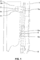
- the present invention relates to an assembly of a fuel chute 2 and a chute of a liquid agent 1.
- Each chute can form an already mounted unit with a respective tank or a respective tank can be formed. be subsequently secured to each chute, the reservoirs not being shown in the figures.
- the chutes 1, 2 extend substantially parallel to one another at least over a portion of their length from a respective filling opening or filling head. It is possible that the filling heads of the two chutes 1, 2 are secured together, advantageously by latching means such as two open rings secured together by partially surrounding a respective filling head, but this is not necessarily necessary in the case of within the scope of the present invention.
- the assembly is provided with means 3 to 6, 6a for securing the two chutes 1, 2 to one another in order to hold the chutes 1, 2 over at least part of their length with respect to each other.
- the securing means 3 to 6, 6a are made, firstly, by a double clip 3 passing through a first lug 4 carried by a portion 1a of one or secured to a first chute 1 from among the fuel 2 and liquid agent 1 chutes and a portion 2a of one or secured to a second chute 2 from among the fuel 2 and agent chutes liquid 1.
- the securing means 3 to 6, 6a are also produced, secondly, by a second tab 5 secured to a portion 2a of or secured to the second chute 2 penetrating into at least one groove 6 carried by the periphery of a portion 1a of or secured to the first chute 1.
- the word portion designates an element in its entity which is secured to a respective chute.
- the two spaced securing points are made at different locations of the portion, that is to say of the element secured to a respective chute.
- the securing means 3 to 6, 6a can directly secure the chutes 1, 2 to each other by portions of the chute.
- the joining can relate to an element associated with the chute.
- this element may be a degassing capacity forming part or not of the chute by being either in one piece with one of the two chutes 1, 2, such as for example a degassing capacity of a fuel chute 2 or being secured, advantageously removably, with one of the two chutes 1, 2.
- the clip 3 may be of elongated shape comprising at each of two opposite ends a pointed head 3a followed by a flange 3b more inside the clip 3 than the pointed head 3a associated.
- a spacing can be provided between each collar 3b and the associated pointed head 3a.
- This spacing may correspond, at one end of the clip 3, to a thickness of the first tab 4 and, at the other end of the clip 3, to the thickness of the portion 2a of or secured to the second chute. 2.
- the collar 3b and the associated pointed head 3a can enclose the first tab 4 or the portion 2a respectively between them or secured to the second chute 2.
- the clip 3 is a securing means as effective as a screw but is easier to assemble.
- the two flanges 3b blocking in opposite directions from one another, prevent an outgoing movement of the clip 3 from the first part at one of its ends and from the portion 2a of or secured to the second chute 2 at its other end.
- the first tab 4 can be pierced with an oblong hole 7 for a passage of the clip 3 in its interior, visible at the figure 1 without the presence of the clip.
- the oblong hole 7 can extend in length parallel to the first chute 1, leaving a take-up play in its length for positioning the clip 3 in its interior. Ease of assembly is obtained, the clip 3 possibly having a positioning clearance in the oblong hole 7, taking into account the manufacturing disparities between different first chutes 1 or different second chutes 2.
- the portion 2a of or secured to the second chute 2 can be a portion of a degassing capacity 2a integrated into the second chute 2.
- the degassing capacity 2a of the second chute 2 can undergo a shape adaptation with a part of the degassing capacity 2a locally crushed to form a flat receiving surface 9 for the passage of the clip 3, this receiving surface being visible at the figure 1 being covered by the first tab 4.
- the portion 2a can also be made integral with the second chute 2 in a removable manner.
- the chutes 1, 2 are advantageously cylindrical and do not have a thick wall. It is therefore preferred to make the connection between the chutes 1, 2 by at least one element 1a, 2a fixed to one of the two chutes 1, 2.
- the degassing capacity 1a of one 1 of the two chutes 1, 2 with the degassing capacity 2a of the other chute 2 in order to have more room to make a connection, of a on the one hand, by a clip 3 and, on the other hand, by a second tab 5 carried by the degassing capacity 2a of the second chute 2 inserting into at least one groove 6 as a housing carried by the degassing capacity 1a of the first chute 1.
- the pointed head 3a at each end of the clip 3 is a conical or slotted head.
- the split head 3a allows a reduction in the size of the head when it is introduced into a passage provided in the first tab 4 carried by the first chute 1 or a portion 1a secured to the first chute 1 and in a portion 2a of or secured to the second chute 2.
- the end portions of the pointed head 3a move away from each other after having passed through the first tab 4 or the portion 2a of or secured to the second chute 2.
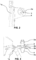
- the second tab 5 secured to the second chute 2 or to a portion 2a secured to the second chute 2 can be inserted between and under two tabs 6a extending at a distance from the periphery of the first chute 1 or a portion 1a secured at the first chute 1.
- a groove 6, visible at the figure 5 can be present under each of the two tabs 6a.
- Each of the two tabs 6a covers a portion of a longitudinal edge of the second lug 5. The securing of the second lug 5 to the second chute or to a portion 2a of the second chute can be obtained by welding.
- the two tabs 6a can be opened at their free end for insertion of the opposite longitudinal edges of the second tab 5 under a respective tab 6a.
- the distance spacing each of the tabs 6a from the periphery of the first chute 1 or of the portion 1a secured to the first chute 1 may correspond to a thickness of the second tab 5 with the addition of a clearance just sufficient for insertion of the second. tab 5 under each of the tabs 6a so that the longitudinal edges of the second tab 5 are retained by friction under a respective tab 6a.
- This connection with two tabs 6a and a second tab 5 is similar to a sliding connection which may have a slight swiveling possible to take into account the dispersions in the course of the first chute 1.
- the portion 1a of or secured to the first chute 1 carrying the tabs 6a can be a degassing capacity 1a secured to the first chute 1.
- This degassing capacity 1a can be secured by latching means 8 removable from the first chute 1, the latching means being visible from the figure 1 .
- the first chute 1 may be the liquid agent chute and the second chute 2 may be the fuel chute 2.
- the two chutes 1, 2 may be cylindrical in shape, the fuel chute 2 having a larger diameter than the chute. liquid agent.
- the degassing capacity 2a of the fuel chute 2 can be of larger dimension than the degassing capacity 1a of the liquid agent chute 1.
- the degassing capacity 2a of the fuel spout 2 can be integral with the fuel spout 2 by being obtained by blowing while the degassing capacity 1a of the liquid agent spout 1 can be attached to the spout.
- liquid agent by latching means 8 for example of the open ring type partially surrounding the liquid agent chute, the ends of the open ring moving apart when the ring is inserted around the wall of the liquid agent chute 1 then the broken ring being held by elastic return against the wall of the liquid agent chute 1.
- the invention also relates to a system formed of a fuel supply device and a liquid agent supply device in a motor vehicle, each device comprising a tank supplied by a chute.
- each device comprising a tank supplied by a chute.
- the two chutes 1, 2 are joined together and form an assembly as described above.
- the system may include a degassing capacity 1a, 2a for each of the supply devices, the degassing capacities being integral with or integrally with their respective chute 1, 2.
- the connection between the two chutes 1, 2 can be made between the respective degassing capacities 1a, 2a.
- the liquid agent supply device is a reducing agent supply device for selective catalytic reduction of nitrogen oxides discharged from the heat engine via the exhaust line.
- the reducing agent supply device supplies a reducing agent injector into the exhaust line.
- the reducing agent which preferably turns into ammonia effects the reduction of nitrogen oxides in a catalytic reduction catalyst disposed downstream of the injector in the exhaust line with reference to the path of the exhaust gases.
Landscapes
- Engineering & Computer Science (AREA)
- Life Sciences & Earth Sciences (AREA)
- Sustainable Development (AREA)
- Sustainable Energy (AREA)
- Chemical & Material Sciences (AREA)
- Combustion & Propulsion (AREA)
- Transportation (AREA)
- Mechanical Engineering (AREA)
- Cooling, Air Intake And Gas Exhaust, And Fuel Tank Arrangements In Propulsion Units (AREA)
Claims (10)
- Anordnung einer Brennstoffrutsche (2) und einer Flüssigkeitsmittelrutsche (1), wobei sich die Rutschen (1, 2) von einer jeweiligen Füllöffnung zumindest teilweise parallel zueinander erstrecken, wobei die Anordnung mit Sicherungsmitteln (3 bis 6, 6a) der beiden Rutschen (1, 2) zwischen ihnen, so dass in einem Abstand von den Füllöffnungen die Sicherungsmittel (3 bis 6, 6a) werden einerseits durch einen Doppelclip (3) erzeugt, der durch eine erste Lasche (4) verläuft, die von einem Teil (1a) einer getragen wird oder an einer ersten Rutsche (1) zwischen den Kraftstoffrutschen (2) und befestigt ist flüssiges Mittel (1) und ein Teil (2a) von einem oder einem Integral mit einer zweiten Rutsche (2) zwischen den Rutschen des Brennstoffs (2) und des flüssigen Mittels (1) und andererseits durch eine zweite Lasche (5) gesichert an einem Abschnitt (2a) von oder an der zweiten Rutsche (2) befestigt, der in mindestens eine Nut (6) eindringt, die von der Peripherie eines Abschnitts (1a) getragen wird oder an der ersten Rutsche (1) befestigt ist, der ersten und zweiten Beine (4, 5) sind voneinander beabstandet.
- Anordnung nach Anspruch 1, wobei der Clip (3) eine längliche Form aufweist, die an jedem der beiden gegenüberliegenden Enden einen spitzen Kopf (3a) umfasst, gefolgt von einem Flansch (3b), der mehr im Inneren des Clips (3) liegt als der zugehörige spitze Kopf (3a), wobei ein Abstand zwischen jedem Flansch (3b) und dem zugehörigen spitzen Kopf (3a) vorgesehen ist und an einem Ende des Clips (3) einer Dicke der ersten Lasche (4) und am anderen Ende entspricht Ende des Clips (3) auf die Dicke des Abschnitts (2a) oder der Befestigung an der zweiten Rutsche (2), wobei der Kragen (3b) und der zugehörige spitze Kopf (3a) zwischen ihnen bzw der ersten Lasche (4) festgeklemmt sind) oder der Teil (2a) der zweiten Rutsche (2) oder an dieser befestigt.
- Anordnung nach Anspruch 2, bei der die erste Lasche (4) mit einem länglichen Loch (7) zum Durchführen des Clips (3) in seinem Inneren durchbohrt ist, wobei sich das längliche Loch (7) parallel zur ersten Rutsche erstreckt (1), wobei ein Aufwickelspiel in seiner Länge verbleibt, um den Clip (3) darin zu positionieren.
- Anordnung nach einem der beiden vorhergehenden Ansprüche, bei der der Teil (2a) der zweiten Rutsche (2) oder ein integraler Bestandteil der zweiten Rutsche (2) ein Teil einer Entgasungskapazität (2a) ist, die in die zweite Rutsche (2) integriert ist.
- Anordnung nach einem der drei vorhergehenden Ansprüche, bei der der spitze Kopf (3a) ein sich verjüngender oder geschlitzter Kopf ist.
- Anordnung nach einem der vorhergehenden Ansprüch, bei der die zweite Lasche (5), die an dem Abschnitt (2a) der zweiten Rutsche (2) befestigt ist oder an der zweiten Rutsche (2) befestigt ist, zwischen und unter zwei Zungen (6a) eingeführt wird, die sich in einem Abstand erstrecken. des Umfangs des Abschnitts (1a) oder der Befestigung an der ersten Rutsche (1) durch Öffnen an ihrem freien Ende zum Einführen der gegenüberliegenden Längskanten der zweiten Lasche (5) unter eine jeweilige Zunge (6a) den Abstand Zungen (6a) des Umfangs des Abschnitts (1a) oder an der Premi- Ära- Rutsche (1) befestigt, die einer Dicke des zweiten Schenkels (5) entspricht, wobei gerade noch genügend Spiel zum Einsetzen der zweiten Lasche (5) hinzugefügt wird in der Nut (6) vorhanden unter jedem der Zungen (6a).
- Anordnung gemäß dem vorhergehenden Anspruch, bei der der Teil (1a) der ersten Rutsche (1), der die Laschen (6a) trägt, an dieser befestigt ist oder eine Entgasungskapazität (1a) aufweist, die an der ersten Rutsche (1) mittels eines abnehmbaren Schnappverschlusses befestigt ist -Schlösser (8).
- Anordnung nach einem vorhergehenden Anspruch, wobei die erste Rutsche (1) die Flüssigkeitsmittelrutsche und die zweite Rutsche (2) die Kraftstoffrutsche (2) ist.
- System, das aus einer Kraftstoffzufuhrvorrichtung und einer Flüssigkeitsmittelzufuhrvorrichtung in einem Kraftfahrzeug gebildet ist, wobei jede Vorrichtung einen Tank umfasst, der von einer Rutsche (1, 2) versorgt wird, dadurch gekennzeichnet, dass die beiden Rutschen (1, 2) miteinander verbunden sind und eine bilden Montage nach einem der vorstehenden Ansprüche.
- System nach dem vorhergehenden Anspruch, bei dem die Flüssigmittelzufuhrvorrichtung eine Reduktionsmittelzufuhrvorrichtung zur selektiven katalytischen Reduktion ist.
Applications Claiming Priority (2)
| Application Number | Priority Date | Filing Date | Title |
|---|---|---|---|
| FR1757787A FR3070326B1 (fr) | 2017-08-22 | 2017-08-22 | Ensemble d’une goulotte de carburant et d’une goulotte d’un agent liquide solidarisees ensemble |
| PCT/FR2018/051829 WO2019038489A1 (fr) | 2017-08-22 | 2018-07-18 | Ensemble d'une goulotte de carburant et d'une goulotte d'un agent liquide solidarisees ensemble |
Publications (2)
| Publication Number | Publication Date |
|---|---|
| EP3672822A1 EP3672822A1 (de) | 2020-07-01 |
| EP3672822B1 true EP3672822B1 (de) | 2021-07-14 |
Family
ID=60020160
Family Applications (1)
| Application Number | Title | Priority Date | Filing Date |
|---|---|---|---|
| EP18752586.0A Active EP3672822B1 (de) | 2017-08-22 | 2018-07-18 | Anordnung aus zusammen befestigtem brennstoffrohr und flüssigmittelrohr |
Country Status (4)
| Country | Link |
|---|---|
| EP (1) | EP3672822B1 (de) |
| FR (1) | FR3070326B1 (de) |
| MA (1) | MA49938B1 (de) |
| WO (1) | WO2019038489A1 (de) |
Families Citing this family (1)
| Publication number | Priority date | Publication date | Assignee | Title |
|---|---|---|---|---|
| DE102020126002A1 (de) | 2020-10-05 | 2022-04-07 | Röchling Automotive SE & Co. KG | Leitungssystem, Befüllanordnung mit Leitungssystem sowie Verfahren zur Herstellung eines Leitungssystems |
Family Cites Families (4)
| Publication number | Priority date | Publication date | Assignee | Title |
|---|---|---|---|---|
| DE4023094C2 (de) * | 1989-07-29 | 1996-12-12 | Volkswagen Ag | Kunststoff-Kraftstoffbehälter für ein Kraftfahrzeug |
| DE4014589C1 (de) * | 1990-05-07 | 1991-08-08 | Trw United-Carr Gmbh & Co Kg, 6753 Enkenbach-Alsenborn, De | |
| FR2983165B1 (fr) * | 2011-11-30 | 2013-11-22 | Faurecia Interieur Ind | Element de vehicule |
| FR3034052B1 (fr) | 2015-03-27 | 2017-03-31 | Peugeot Citroen Automobiles Sa | Ensemble de reservoirs de fluides consommables pour vehicule automobile |
-
2017
- 2017-08-22 FR FR1757787A patent/FR3070326B1/fr not_active Expired - Fee Related
-
2018
- 2018-07-18 EP EP18752586.0A patent/EP3672822B1/de active Active
- 2018-07-18 MA MA49938A patent/MA49938B1/fr unknown
- 2018-07-18 WO PCT/FR2018/051829 patent/WO2019038489A1/fr unknown
Also Published As
| Publication number | Publication date |
|---|---|
| FR3070326B1 (fr) | 2019-09-13 |
| FR3070326A1 (fr) | 2019-03-01 |
| EP3672822A1 (de) | 2020-07-01 |
| MA49938A (fr) | 2021-03-31 |
| WO2019038489A1 (fr) | 2019-02-28 |
| MA49938B1 (fr) | 2021-09-30 |
Similar Documents
| Publication | Publication Date | Title |
|---|---|---|
| EP3274206B1 (de) | Anordnung aus tanks für verbrauchsflüssigkeiten für ein kraftfahrzeug | |
| CA2647145C (fr) | Dispositif de guidage d'un element dans un orifice d'une paroi de chambre de combustion de turbomachine | |
| EP3672822B1 (de) | Anordnung aus zusammen befestigtem brennstoffrohr und flüssigmittelrohr | |
| EP3609729B1 (de) | Anordnung von zwei fluidbehältern mit befestigten rohren | |
| FR2761626A1 (fr) | Procede d'assemblage par soudage de pieces de tolerie | |
| EP3814616B1 (de) | Leitvorrichtung in einer brennkammer | |
| EP0621153B1 (de) | Einfüllstutzen für Kraftstofftank, insbesondere für Kraftfahrzeug | |
| WO2019155142A1 (fr) | Ensemble d'alimentation en carburant ou en produit de depollution d'un vehicule automobile | |
| FR2866419A1 (fr) | Boite collectrice munie d'une tubulure de raccordement pour un echangeur de chaleur brase. | |
| EP2471152B1 (de) | Kammflansch für hochspannungskabel | |
| EP3807114B1 (de) | Behälter mit rohren zur erleichterung seiner verpackung | |
| EP3752381B1 (de) | Anordnung mit einem versteifungsträger und einem gurt für einen kraftstofftank eines kraftfahrzeuges | |
| EP2909468A1 (de) | Flansch zur befestigung von mindestens einem injektor an einem zylinderkopf einer brennkraftmaschine | |
| WO2023285512A1 (fr) | Dispositif de fixation d'un élément sur une partie d'un véhicule automobile | |
| EP3297867B1 (de) | Tank mit integrierter schürze | |
| EP2940363B1 (de) | Anschlussvorrichtung zwischen der öffnung eines flüssigkeitsbehälters und einer leitung | |
| FR3014484B1 (fr) | Ecran de protection thermique pour dispositif de sortie de gaz d'echappement de vehicule automobile | |
| WO2017144799A1 (fr) | Element de supportage d'une piece de maintien de composants fixee sur une piece de structure de vehicule automobile | |
| FR2878296A1 (fr) | Fermoir a ressort pour serrage de sangle | |
| EP3610140A1 (de) | Fluidbehälter mit durch eine klemme gehaltenem aussenrohr | |
| FR3085632A1 (fr) | Dispositif de liaison entre tetes de tubulure de reservoirs et vehicule automobile equipe d’un tel dispositif | |
| FR3072663A3 (fr) | Dispositif d'introduction d'un produit additif dans une installation d'alimentation en essence ou gas-oil d'un vehicule a moteur. | |
| WO2006045940A1 (fr) | Dispositif de traitement des gaz d'echappement pour vehicule automobile et vehicule correspondant | |
| FR2775507A1 (fr) | Raccord encliquetable pour conduit de fluide, en particulier pour vehicule automobile | |
| FR2955900A1 (fr) | Dispositif d'attenuation acoustique pour ligne d'admission d'un moteur thermique, tuyau flexible et ligne d'admission l'incorporant |
Legal Events
| Date | Code | Title | Description |
|---|---|---|---|
| STAA | Information on the status of an ep patent application or granted ep patent |
Free format text: STATUS: UNKNOWN |
|
| STAA | Information on the status of an ep patent application or granted ep patent |
Free format text: STATUS: THE INTERNATIONAL PUBLICATION HAS BEEN MADE |
|
| PUAI | Public reference made under article 153(3) epc to a published international application that has entered the european phase |
Free format text: ORIGINAL CODE: 0009012 |
|
| STAA | Information on the status of an ep patent application or granted ep patent |
Free format text: STATUS: REQUEST FOR EXAMINATION WAS MADE |
|
| 17P | Request for examination filed |
Effective date: 20200115 |
|
| AK | Designated contracting states |
Kind code of ref document: A1 Designated state(s): AL AT BE BG CH CY CZ DE DK EE ES FI FR GB GR HR HU IE IS IT LI LT LU LV MC MK MT NL NO PL PT RO RS SE SI SK SM TR |
|
| AX | Request for extension of the european patent |
Extension state: BA ME |
|
| RAP1 | Party data changed (applicant data changed or rights of an application transferred) |
Owner name: PSA AUTOMOBILES SA |
|
| DAX | Request for extension of the european patent (deleted) | ||
| RAV | Requested validation state of the european patent: fee paid |
Extension state: MA Effective date: 20200115 |
|
| GRAP | Despatch of communication of intention to grant a patent |
Free format text: ORIGINAL CODE: EPIDOSNIGR1 |
|
| STAA | Information on the status of an ep patent application or granted ep patent |
Free format text: STATUS: GRANT OF PATENT IS INTENDED |
|
| INTG | Intention to grant announced |
Effective date: 20210302 |
|
| RIN1 | Information on inventor provided before grant (corrected) |
Inventor name: LE GUYADER, GAEL |
|
| GRAS | Grant fee paid |
Free format text: ORIGINAL CODE: EPIDOSNIGR3 |
|
| GRAA | (expected) grant |
Free format text: ORIGINAL CODE: 0009210 |
|
| STAA | Information on the status of an ep patent application or granted ep patent |
Free format text: STATUS: THE PATENT HAS BEEN GRANTED |
|
| AK | Designated contracting states |
Kind code of ref document: B1 Designated state(s): AL AT BE BG CH CY CZ DE DK EE ES FI FR GB GR HR HU IE IS IT LI LT LU LV MC MK MT NL NO PL PT RO RS SE SI SK SM TR |
|
| REG | Reference to a national code |
Ref country code: GB Ref legal event code: FG4D Free format text: NOT ENGLISH |
|
| REG | Reference to a national code |
Ref country code: DE Ref legal event code: R096 Ref document number: 602018020143 Country of ref document: DE |
|
| REG | Reference to a national code |
Ref country code: IE Ref legal event code: FG4D Free format text: LANGUAGE OF EP DOCUMENT: FRENCH |
|
| REG | Reference to a national code |
Ref country code: DE Ref legal event code: R084 Ref document number: 602018020143 Country of ref document: DE |
|
| REG | Reference to a national code |
Ref country code: AT Ref legal event code: REF Ref document number: 1410368 Country of ref document: AT Kind code of ref document: T Effective date: 20210815 |
|
| REG | Reference to a national code |
Ref country code: MA Ref legal event code: VAGR Ref document number: 49938 Country of ref document: MA Kind code of ref document: B1 |
|
| REG | Reference to a national code |
Ref country code: GB Ref legal event code: 746 Effective date: 20210910 |
|
| REG | Reference to a national code |
Ref country code: LT Ref legal event code: MG9D |
|
| REG | Reference to a national code |
Ref country code: NL Ref legal event code: MP Effective date: 20210714 |
|
| REG | Reference to a national code |
Ref country code: AT Ref legal event code: MK05 Ref document number: 1410368 Country of ref document: AT Kind code of ref document: T Effective date: 20210714 |
|
| PG25 | Lapsed in a contracting state [announced via postgrant information from national office to epo] |
Ref country code: SE Free format text: LAPSE BECAUSE OF FAILURE TO SUBMIT A TRANSLATION OF THE DESCRIPTION OR TO PAY THE FEE WITHIN THE PRESCRIBED TIME-LIMIT Effective date: 20210714 Ref country code: RS Free format text: LAPSE BECAUSE OF FAILURE TO SUBMIT A TRANSLATION OF THE DESCRIPTION OR TO PAY THE FEE WITHIN THE PRESCRIBED TIME-LIMIT Effective date: 20210714 Ref country code: HR Free format text: LAPSE BECAUSE OF FAILURE TO SUBMIT A TRANSLATION OF THE DESCRIPTION OR TO PAY THE FEE WITHIN THE PRESCRIBED TIME-LIMIT Effective date: 20210714 Ref country code: FI Free format text: LAPSE BECAUSE OF FAILURE TO SUBMIT A TRANSLATION OF THE DESCRIPTION OR TO PAY THE FEE WITHIN THE PRESCRIBED TIME-LIMIT Effective date: 20210714 Ref country code: ES Free format text: LAPSE BECAUSE OF FAILURE TO SUBMIT A TRANSLATION OF THE DESCRIPTION OR TO PAY THE FEE WITHIN THE PRESCRIBED TIME-LIMIT Effective date: 20210714 Ref country code: LT Free format text: LAPSE BECAUSE OF FAILURE TO SUBMIT A TRANSLATION OF THE DESCRIPTION OR TO PAY THE FEE WITHIN THE PRESCRIBED TIME-LIMIT Effective date: 20210714 Ref country code: AT Free format text: LAPSE BECAUSE OF FAILURE TO SUBMIT A TRANSLATION OF THE DESCRIPTION OR TO PAY THE FEE WITHIN THE PRESCRIBED TIME-LIMIT Effective date: 20210714 Ref country code: BG Free format text: LAPSE BECAUSE OF FAILURE TO SUBMIT A TRANSLATION OF THE DESCRIPTION OR TO PAY THE FEE WITHIN THE PRESCRIBED TIME-LIMIT Effective date: 20211014 Ref country code: NL Free format text: LAPSE BECAUSE OF FAILURE TO SUBMIT A TRANSLATION OF THE DESCRIPTION OR TO PAY THE FEE WITHIN THE PRESCRIBED TIME-LIMIT Effective date: 20210714 Ref country code: PT Free format text: LAPSE BECAUSE OF FAILURE TO SUBMIT A TRANSLATION OF THE DESCRIPTION OR TO PAY THE FEE WITHIN THE PRESCRIBED TIME-LIMIT Effective date: 20211115 Ref country code: NO Free format text: LAPSE BECAUSE OF FAILURE TO SUBMIT A TRANSLATION OF THE DESCRIPTION OR TO PAY THE FEE WITHIN THE PRESCRIBED TIME-LIMIT Effective date: 20211014 |
|
| PG25 | Lapsed in a contracting state [announced via postgrant information from national office to epo] |
Ref country code: PL Free format text: LAPSE BECAUSE OF FAILURE TO SUBMIT A TRANSLATION OF THE DESCRIPTION OR TO PAY THE FEE WITHIN THE PRESCRIBED TIME-LIMIT Effective date: 20210714 Ref country code: LV Free format text: LAPSE BECAUSE OF FAILURE TO SUBMIT A TRANSLATION OF THE DESCRIPTION OR TO PAY THE FEE WITHIN THE PRESCRIBED TIME-LIMIT Effective date: 20210714 Ref country code: GR Free format text: LAPSE BECAUSE OF FAILURE TO SUBMIT A TRANSLATION OF THE DESCRIPTION OR TO PAY THE FEE WITHIN THE PRESCRIBED TIME-LIMIT Effective date: 20211015 |
|
| REG | Reference to a national code |
Ref country code: CH Ref legal event code: PL |
|
| REG | Reference to a national code |
Ref country code: BE Ref legal event code: MM Effective date: 20210731 |
|
| REG | Reference to a national code |
Ref country code: DE Ref legal event code: R097 Ref document number: 602018020143 Country of ref document: DE |
|
| PG25 | Lapsed in a contracting state [announced via postgrant information from national office to epo] |
Ref country code: LI Free format text: LAPSE BECAUSE OF NON-PAYMENT OF DUE FEES Effective date: 20210731 Ref country code: DK Free format text: LAPSE BECAUSE OF FAILURE TO SUBMIT A TRANSLATION OF THE DESCRIPTION OR TO PAY THE FEE WITHIN THE PRESCRIBED TIME-LIMIT Effective date: 20210714 Ref country code: CH Free format text: LAPSE BECAUSE OF NON-PAYMENT OF DUE FEES Effective date: 20210731 |
|
| PLBE | No opposition filed within time limit |
Free format text: ORIGINAL CODE: 0009261 |
|
| STAA | Information on the status of an ep patent application or granted ep patent |
Free format text: STATUS: NO OPPOSITION FILED WITHIN TIME LIMIT |
|
| PG25 | Lapsed in a contracting state [announced via postgrant information from national office to epo] |
Ref country code: SM Free format text: LAPSE BECAUSE OF FAILURE TO SUBMIT A TRANSLATION OF THE DESCRIPTION OR TO PAY THE FEE WITHIN THE PRESCRIBED TIME-LIMIT Effective date: 20210714 Ref country code: SK Free format text: LAPSE BECAUSE OF FAILURE TO SUBMIT A TRANSLATION OF THE DESCRIPTION OR TO PAY THE FEE WITHIN THE PRESCRIBED TIME-LIMIT Effective date: 20210714 Ref country code: RO Free format text: LAPSE BECAUSE OF FAILURE TO SUBMIT A TRANSLATION OF THE DESCRIPTION OR TO PAY THE FEE WITHIN THE PRESCRIBED TIME-LIMIT Effective date: 20210714 Ref country code: MC Free format text: LAPSE BECAUSE OF FAILURE TO SUBMIT A TRANSLATION OF THE DESCRIPTION OR TO PAY THE FEE WITHIN THE PRESCRIBED TIME-LIMIT Effective date: 20210714 Ref country code: LU Free format text: LAPSE BECAUSE OF NON-PAYMENT OF DUE FEES Effective date: 20210718 Ref country code: EE Free format text: LAPSE BECAUSE OF FAILURE TO SUBMIT A TRANSLATION OF THE DESCRIPTION OR TO PAY THE FEE WITHIN THE PRESCRIBED TIME-LIMIT Effective date: 20210714 Ref country code: CZ Free format text: LAPSE BECAUSE OF FAILURE TO SUBMIT A TRANSLATION OF THE DESCRIPTION OR TO PAY THE FEE WITHIN THE PRESCRIBED TIME-LIMIT Effective date: 20210714 Ref country code: AL Free format text: LAPSE BECAUSE OF FAILURE TO SUBMIT A TRANSLATION OF THE DESCRIPTION OR TO PAY THE FEE WITHIN THE PRESCRIBED TIME-LIMIT Effective date: 20210714 |
|
| 26N | No opposition filed |
Effective date: 20220419 |
|
| PG25 | Lapsed in a contracting state [announced via postgrant information from national office to epo] |
Ref country code: IT Free format text: LAPSE BECAUSE OF FAILURE TO SUBMIT A TRANSLATION OF THE DESCRIPTION OR TO PAY THE FEE WITHIN THE PRESCRIBED TIME-LIMIT Effective date: 20210714 Ref country code: IE Free format text: LAPSE BECAUSE OF NON-PAYMENT OF DUE FEES Effective date: 20210718 Ref country code: BE Free format text: LAPSE BECAUSE OF NON-PAYMENT OF DUE FEES Effective date: 20210731 |
|
| PG25 | Lapsed in a contracting state [announced via postgrant information from national office to epo] |
Ref country code: CY Free format text: LAPSE BECAUSE OF FAILURE TO SUBMIT A TRANSLATION OF THE DESCRIPTION OR TO PAY THE FEE WITHIN THE PRESCRIBED TIME-LIMIT Effective date: 20210714 |
|
| PG25 | Lapsed in a contracting state [announced via postgrant information from national office to epo] |
Ref country code: HU Free format text: LAPSE BECAUSE OF FAILURE TO SUBMIT A TRANSLATION OF THE DESCRIPTION OR TO PAY THE FEE WITHIN THE PRESCRIBED TIME-LIMIT; INVALID AB INITIO Effective date: 20180718 |
|
| PGFP | Annual fee paid to national office [announced via postgrant information from national office to epo] |
Ref country code: FR Payment date: 20230621 Year of fee payment: 6 |
|
| PGFP | Annual fee paid to national office [announced via postgrant information from national office to epo] |
Ref country code: GB Payment date: 20230620 Year of fee payment: 6 |
|
| PGFP | Annual fee paid to national office [announced via postgrant information from national office to epo] |
Ref country code: DE Payment date: 20230620 Year of fee payment: 6 |
|
| REG | Reference to a national code |
Ref country code: DE Ref legal event code: R081 Ref document number: 602018020143 Country of ref document: DE Owner name: STELLANTIS AUTO SAS, FR Free format text: FORMER OWNER: PSA AUTOMOBILES SA, POISSY, FR |
|
| PG25 | Lapsed in a contracting state [announced via postgrant information from national office to epo] |
Ref country code: MK Free format text: LAPSE BECAUSE OF FAILURE TO SUBMIT A TRANSLATION OF THE DESCRIPTION OR TO PAY THE FEE WITHIN THE PRESCRIBED TIME-LIMIT Effective date: 20210714 |