EP3672787B1 - Verfahren zum herstellen eines formbauteils, sowie formbauteil hergestellt mit einem derartigen verfahren - Google Patents
Verfahren zum herstellen eines formbauteils, sowie formbauteil hergestellt mit einem derartigen verfahren Download PDFInfo
- Publication number
- EP3672787B1 EP3672787B1 EP18752752.8A EP18752752A EP3672787B1 EP 3672787 B1 EP3672787 B1 EP 3672787B1 EP 18752752 A EP18752752 A EP 18752752A EP 3672787 B1 EP3672787 B1 EP 3672787B1
- Authority
- EP
- European Patent Office
- Prior art keywords
- produced
- molded component
- layer
- spraying process
- shaped component
- Prior art date
- Legal status (The legal status is an assumption and is not a legal conclusion. Google has not performed a legal analysis and makes no representation as to the accuracy of the status listed.)
- Active
Links
Images
Classifications
-
- B—PERFORMING OPERATIONS; TRANSPORTING
- B29—WORKING OF PLASTICS; WORKING OF SUBSTANCES IN A PLASTIC STATE IN GENERAL
- B29C—SHAPING OR JOINING OF PLASTICS; SHAPING OF MATERIAL IN A PLASTIC STATE, NOT OTHERWISE PROVIDED FOR; AFTER-TREATMENT OF THE SHAPED PRODUCTS, e.g. REPAIRING
- B29C70/00—Shaping composites, i.e. plastics material comprising reinforcements, fillers or preformed parts, e.g. inserts
- B29C70/04—Shaping composites, i.e. plastics material comprising reinforcements, fillers or preformed parts, e.g. inserts comprising reinforcements only, e.g. self-reinforcing plastics
- B29C70/28—Shaping operations therefor
- B29C70/30—Shaping by lay-up, i.e. applying fibres, tape or broadsheet on a mould, former or core; Shaping by spray-up, i.e. spraying of fibres on a mould, former or core
- B29C70/305—Spray-up of reinforcing fibres with or without matrix to form a non-coherent mat in or on a mould
-
- B—PERFORMING OPERATIONS; TRANSPORTING
- B29—WORKING OF PLASTICS; WORKING OF SUBSTANCES IN A PLASTIC STATE IN GENERAL
- B29C—SHAPING OR JOINING OF PLASTICS; SHAPING OF MATERIAL IN A PLASTIC STATE, NOT OTHERWISE PROVIDED FOR; AFTER-TREATMENT OF THE SHAPED PRODUCTS, e.g. REPAIRING
- B29C64/00—Additive manufacturing, i.e. manufacturing of three-dimensional [3D] objects by additive deposition, additive agglomeration or additive layering, e.g. by 3D printing, stereolithography or selective laser sintering
- B29C64/10—Processes of additive manufacturing
- B29C64/106—Processes of additive manufacturing using only liquids or viscous materials, e.g. depositing a continuous bead of viscous material
-
- B—PERFORMING OPERATIONS; TRANSPORTING
- B29—WORKING OF PLASTICS; WORKING OF SUBSTANCES IN A PLASTIC STATE IN GENERAL
- B29C—SHAPING OR JOINING OF PLASTICS; SHAPING OF MATERIAL IN A PLASTIC STATE, NOT OTHERWISE PROVIDED FOR; AFTER-TREATMENT OF THE SHAPED PRODUCTS, e.g. REPAIRING
- B29C64/00—Additive manufacturing, i.e. manufacturing of three-dimensional [3D] objects by additive deposition, additive agglomeration or additive layering, e.g. by 3D printing, stereolithography or selective laser sintering
- B29C64/10—Processes of additive manufacturing
- B29C64/188—Processes of additive manufacturing involving additional operations performed on the added layers, e.g. smoothing, grinding or thickness control
- B29C64/194—Processes of additive manufacturing involving additional operations performed on the added layers, e.g. smoothing, grinding or thickness control during lay-up
-
- B—PERFORMING OPERATIONS; TRANSPORTING
- B33—ADDITIVE MANUFACTURING TECHNOLOGY
- B33Y—ADDITIVE MANUFACTURING, i.e. MANUFACTURING OF THREE-DIMENSIONAL [3D] OBJECTS BY ADDITIVE DEPOSITION, ADDITIVE AGGLOMERATION OR ADDITIVE LAYERING, e.g. BY 3D PRINTING, STEREOLITHOGRAPHY OR SELECTIVE LASER SINTERING
- B33Y10/00—Processes of additive manufacturing
-
- B—PERFORMING OPERATIONS; TRANSPORTING
- B33—ADDITIVE MANUFACTURING TECHNOLOGY
- B33Y—ADDITIVE MANUFACTURING, i.e. MANUFACTURING OF THREE-DIMENSIONAL [3D] OBJECTS BY ADDITIVE DEPOSITION, ADDITIVE AGGLOMERATION OR ADDITIVE LAYERING, e.g. BY 3D PRINTING, STEREOLITHOGRAPHY OR SELECTIVE LASER SINTERING
- B33Y80/00—Products made by additive manufacturing
Definitions
- the invention relates to a method for producing a molded component according to the preamble of claim 1. Furthermore, the invention relates to a molded component which is produced by such a method.
- WO 2015/139095 A1 discloses a method and apparatus for producing a composite object from a first and a second material.
- D3 CN 106 891 524 describes a 3D printing process and device for the targeted assembly of short fibers in a liquid matrix.
- D7 US 9 457 521 B2 describes a method, a device and a material mixture for the direct digital production of fiber-reinforced parts.
- a molded component is produced by arranging a starting material in a sequence of layers, one above the other, during the printing process. All layers then form the molded component. This is achieved by using starting materials that are in liquid or at least viscous form during printing at a printing temperature and then cool to an ambient temperature after the layer has been formed, whereby the
- Starting materials change their physical state and harden. This enables the layer-by-layer production of a molded component.
- the disadvantage of such molded components is that the mechanical properties, such as the strength of the manufactured molded component, can only be influenced by the choice of starting material.
- thermoplastics such as acrylonitrile butadiene styrene (ABS), polylactide (PLA), acrylates, epoxies, or polyurethanes are typically used as starting materials.
- ABS acrylonitrile butadiene styrene
- PLA polylactide
- acrylates acrylates
- epoxies epoxies
- polyurethanes polyurethane
- the inventive method for producing a molded component with the features of claim 1 has the advantage that the strength of the molded component is particularly high. In particular, this enables the construction of molded components with delicate structures using a conventional 3D printing process, while the molded component still has high strength and, in particular, thus good mechanical resilience.
- the manufacturing method according to the invention comprises at least one further layer, which is produced at least partially from a spraying process using fiber pieces.
- the fiber pieces can improve the mechanical properties of the molded component. This is achieved because the forces acting on the molded component can be better absorbed by the individual fiber pieces contained in the further layer.
- an additional layer produced by the spraying process is provided in the molded component.
- several layers, each comprising a plurality of fiber pieces, which were produced by the spraying process can also be formed in the molded component, which then together ensure better mechanical load-bearing capacity of the molded component.
- the additional layer created by the spraying process comprises fiber pieces made of glass or aramid with a length of approximately 50 mm. This allows for the formation of additional layers in the molded component produced by the spraying process. These layers only slightly increase the weight (mass) of the molded component, yet make a significant contribution to improving the mechanical properties, particularly the strength of the molded component. In addition to short production times due to the 3D printing process, this also allows for a significant reduction in manufacturing costs compared to molded components made entirely of carbon.
- the fiber pieces contained in the further layer are arranged in an oriented manner.
- This is preferably made possible by applying the fiber pieces in the spraying process to the molded component through a nozzle for forming the further layer in such a way that all fiber pieces have the same orientation.
- an anisotropic i.e., arbitrary arrangement of the fiber pieces in the further layer is also possible.
- the The molded component comprises several additional layers produced by spraying, whereby in all additional layers the fiber pieces can be arranged in different directions, i.e. anisotropically.
- a binder for the fiber pieces is also introduced into the additional layer during the spraying process.
- the strength of the additional layer is preferably also increased by the binder at high temperatures or in an aggressive ambient atmosphere, such as salty sea air.
- the direct introduction of the binder in the spraying process eliminates an additional process step in which such a binder is applied to the fibers.
- the binders are preferably formed from hardening synthetic resins, such as epoxy resins and/or reactive resins.
- a thermal treatment of the additional layer can be provided.
- irradiation of the layer with UV rays is also possible, which leads to the hardening of the binder.
- the binder can also contain microballoons as fillers, which can then also lead to an improvement in mechanical properties or a reduction in weight. It is also preferred if, in a final process step, all layers are thermally treated together for curing after the additional layer has been applied.
- a preferred embodiment of the manufacturing method according to the invention provides for the fiber pieces to partially overlap, which can increase the mechanical properties and, in particular, the strength of the molded component.
- the fiber pieces are sprayed on in such a way that partial areas of the fiber pieces overlap, which are then firmly bonded and fixed together by the binding agents.
- the molded components have outer layers that are produced exclusively by the printing process. This makes it possible to produce molded components with delicate outer structures that nevertheless have improved mechanical properties due to the arrangement of an additional layer containing the fiber pieces in the interior.
- all components produced using the conventional 3D printing process can also be manufactured using the method according to the invention, wherein, advantageously, in the manufacturing method according to the invention, the mechanical properties of the entire molded component can be specifically improved and/or adapted by arranging the additional layer containing the fiber pieces in the interior.
- the molded component comprises at least two additional layers, which are produced at least partially by a spraying process.
- This makes it possible to improve the mechanical properties, in particular the strength, via at least two additional layers comprising fiber pieces, wherein the mechanical properties, in particular the strength, can be further increased by at least two additional layers compared to just one additional layer. It is also preferably possible to align the fiber pieces differently in the two additional layers, whereby the mechanical properties of the molded component can be specifically adapted with respect to direction-dependent forces.
- two additional layers of the molded component, produced using the spraying process are arranged directly on top of each other. This allows the thickness of the additional layers produced using the spraying process to be influenced, whereby the mechanical properties of the molded component can also be influenced depending on the application.
- At least two further layers are arranged in the molded component, with At least one layer produced by printing is arranged between the at least two additional layers. This also allows the mechanical properties of the molded component to be specifically enhanced and thus customized depending on the application.
- a further development of the invention shows a method step in which the at least one further layer produced in the spraying process is subjected to a post-treatment, in particular a thermal one, to increase its strength.
- a post-treatment in particular a thermal one
- a purely thermal treatment can be provided, in which the molded component or the further layer comprising the fiber pieces is brought to a specific temperature at which a curing process is activated, in particular due to the binder.
- irradiation of the molded component and/or the further layer comprising the fiber pieces is also possible for curing, with UV radiation preferably being used.
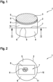
- the Fig. 1 shows a side view of a schematically shown molded component 1, which was produced from a starting material 9 using a 3D printing process according to the invention.
- the starting material 9 is a thermoplastic, such as ABS, PLA, polyurethane, epoxy, acrylate, polycarbonate or Ultem.
- the molded component 1 has a cylindrical outer contour 2 with a circular base area 3 and a corresponding outer surface 4. All outer surfaces of the molded component 1 were produced using a conventional 3D printing process. For this purpose, a geometric model of the molded component 1 is first created, from which individual layers 5 are then determined, which can be produced from the starting material 9 using the 3D printing process.
- the starting material 9 is first heated during the 3D printing process to a temperature at which the aggregate state of the starting material 9 is liquid, in particular viscous.
- the printing process then follows, during which the preheated starting material 9 is printed, thus forming a layer 5. Since the temperature of the starting material 9 drops to the ambient temperature after printing, the starting material 9 hardens. This enables the layer-by-layer formation of the molded component 1.
- a further layer 7 is now produced in the molded component 1 by a spraying process.
- Fig. 1 not shown in detail, fiber pieces 6 are arranged in the further layer 7 in such a way that all fiber pieces 6 of the further layer 7 are aligned in the same direction and partially overlap each other.
- a binder 8 is also sprayed on, which ensures that the fiber pieces 6 are held or fixed in the sprayed-on, aligned position.
- the additional layer 7 provided in the interior of the molded component 1 and produced by the spraying process can significantly increase the mechanical properties of the molded component 1, resulting in the molded component 1 having greater strength.
- Fig. 2 shows a view through the Fig. 1 known molded component 1, wherein the further layer 7 produced in the molded component 1 by the spraying process is now visible.
- the further layer 7 is formed outside the area of the fiber pieces 6 by the starting material 9, which was produced by the classic 3D printing process.
- This allows all molded components 1 that can be produced by means of 3D printing processes to be manufactured, which according to the invention have improved mechanical properties due to the at least one further layer 7 compared to molded components produced only by the 3D printing process.
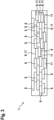
- Fig. 3 shows a schematic representation of the additional layer 7 produced by the spraying process.
- the individual fiber pieces 6 can be seen therein, with all fiber pieces 6 aligned in an orderly manner relative to one another and fixed in this ordered relative arrangement by the binding agent 8 covering or impregnating the fiber pieces 6.
- the fiber pieces 6 have a length of approximately 50 mm and are made of Aramid 11, which leads to a particularly high strength of the molded component 1.
- the molded component having the at least one further layer can be formed not only by a 3D printing process based on the melt layer but also by another 3D printing process, such as stereolithography (SLA) technology, selective laser sintering (SLS) or multi-jet modeling (MJM).
- SLA stereolithography
- SLS selective laser sintering
- MLM multi-jet modeling
Landscapes
- Chemical & Material Sciences (AREA)
- Engineering & Computer Science (AREA)
- Materials Engineering (AREA)
- Manufacturing & Machinery (AREA)
- Mechanical Engineering (AREA)
- Physics & Mathematics (AREA)
- Optics & Photonics (AREA)
- Composite Materials (AREA)
Description
- Die Erfindung betrifft ein Verfahren zum Herstellen eines Formbauteils nach dem Oberbegriff des Anspruchs 1. Ferner betrifft die Erfindung ein Formbauteil, welches durch ein derartiges Verfahren hergestellt ist.
- D1
WO 2015/139095 A1 offenbart ein Verfahren und eine Vorrichtung zur Herstellung eines Verbundobjekts aus einem ersten und einem zweiten Material. - D3
CN 106 891 524 beschreibt ein 3D-Druckverfahren und eine -Vorrichtung für ein gezieltes Zusammenfügen kurze Fasern in einer flüssigen Matrix. - D7
US 9 457 521 B2 - Bei einem bekannten gattungsbildenden 3D-Druckverfahren wird ein Formbauteil hergestellt, indem ein Ausgangsmaterial im Druckverfahren in einer Abfolge von Schichten jeweils übereinander angeordnet wird. Sämtliche Schichten bilden dann das Formbauteil aus. Dies wird erreicht, indem Ausgangsmaterialien verwendet werden, die beim Drucken bei einer Drucktemperatur in flüssiger oder wenigstens zähflüssiger Form vorliegen und dann nach dem Ausbilden der Schicht auf eine Umgebungstemperatur abkühlen, wobei die
- Ausgangsmaterialien den Aggregatzustand ändern und aushärten. Dies ermöglicht das schichtweise Herstellen eines Formbauteils. Nachteilig bei derartig ausgebildeten Formbauteilen ist, dass sich die mechanischen Eigenschaften, wie etwa die Festigkeit des hergestellten Formbauteils, lediglich durch die Wahl des Ausgangsmaterials beeinflussen lassen. Bei gattungsbildenden 3D-Druckverfahren werden üblicherweise thermoplastische Kunststoffe, wie etwa Acrylnitril-Butadien-Styrol (ABS), Polylactide (PLA), Acrylate, Epoxyde oder Polyurethane als Ausgangsmaterial verwendet. Allerdings wird die Materialauswahl allein schon durch die thermischen Anforderungen des Druckverfahrens deutlich eingegrenzt, weshalb Ausgangsmaterialien, die im ausgehärteten Zustand eine hohe Festigkeit aufweisen, sehr selten sind.
- Das erfindungsgemäße Verfahren zum Herstellen eines Formbauteils mit den Merkmalen des Anspruchs 1 hat den Vorteil, dass die Festigkeit des Formbauteils besonders hoch ist. Insbesondere ermöglicht dies den Aufbau von Formbauteilen mit filigranen Strukturen über ein klassisches 3D-Druckverfahren, wobei das Formbauteil dennoch eine hohe Festigkeit und insbesondere damit eine gute mechanische Belastbarkeit besitzt.
- Das erfindungsgemäße Herstellungsverfahren umfasst hierfür wenigstens eine weitere Schicht, die zumindest bereichsweise aus einem Sprühverfahren unter Verwendung von Faserstücken erzeugt wird. Durch die Faserstücke können die mechanischen Eigenschaften des Formbauteils verbessert werden. Erreicht wird dies, da die auf das Formbauteil einwirkenden Kräfte durch die in der weiteren Schicht enthaltenen einzelnen Faserstücke besser absorbiert werden können. Bevorzugt ist eine durch das Sprühverfahren erzeugte weitere Schicht im Formbauteil vorgesehen. Allerdings können auch mehrere jeweils eine Vielzahl von Faserstücken aufweisenden Schichten, die durch das Sprühverfahren hergestellt wurden, im Formbauteil ausgebildet werden, die dann gemeinsam für eine bessere mechanische Belastbarkeit des Formbauteils sorgen. Alternativ ist es aber auch gerade bei einem 3D-Druckverfahren, welches auf der so genannten Multi Jet Modeling (MJM)-Technologie basiert, möglich, dass die weitere Schicht in eine Außenschicht eingebracht wird. Dies ermöglicht erfindungsgemäß die Vorteile des klassischen 3D-Druckverfahrens zu nutzen und Formbauteile, insbesondere Prototypen, in kurzer Zeit herzustellen, wobei die mechanischen Eigenschaften durch das Einbringen der wenigstens einen weiteren Schicht durch das Sprühverfahren in das aus vielen Schichten aufgebaute Formbauteil verbessert werden können und insbesondere die Festigkeit des Formbauteils bei einer mechanischen Belastung verbessert werden kann.
- Die durch das Sprühverfahren erzeugte weitere Schicht weist Faserstücke aus Glas oder Aramid auf, die eine Länge von ungefähr 50mm besitzen. Dies ermöglicht das Ausbilden von mittels des Sprühverfahrens erzeugten weiteren Schichten in dem Formbauteil, die das Eigengewicht (Masse) des Formbauteils nur unwesentlich steigern und dennoch einen großen Beitrag zur Verbesserung der mechanischen Eigenschaften, insbesondere der Festigkeit des Formbauteils, liefern. Neben kurzen Herstellungszeiten aufgrund des 3D-Druckverfahrens erlaubt dies zudem vorteilhaft die Herstellungskosten im Vergleich zu rein aus Carbon gefertigten Formbauteilen deutlich zu reduzieren.
- Vorteilhafte Weiterbildungen des erfindungsgemäßen Herstellungsverfahrens sind in den Unteransprüchen aufgeführt.
- In einer Fortbildung der Erfindung erfolgt die Anordnung der in der weiteren Schicht enthaltenen Faserstücke orientiert. Mit anderen Worten ausgedrückt bedeutet dies, dass sämtliche Faserstücke in einer mit dem Sprühverfahren erzeugten Schicht geordnet ausgerichtet sind, wobei die Längsrichtungen der Faserstücke vorzugsweise parallel und/oder nahezu parallel zueinander angeordnet sind. Dies ermöglicht die Festigkeit des Formbauteils im Vergleich zu einer anisotropen, also ungeordneten Anordnung der Faserstücke in der wenigstens einen weiteren Schicht zu steigern. Dies wird bevorzugt ermöglicht, indem die Faserstücke in dem Sprühverfahren durch eine Düse zum Ausbilden der weiteren Schicht derart auf das Formbauteil aufgebracht werden, dass sämtliche Faserstücke die gleiche Orientierung aufweisen. Alternativ ist jedoch auch eine anisotrope, also beliebige Anordnung der Faserstücke in der weiteren Schicht möglich. Dies erlaubt die mechanischen Eigenschaften des
Formbauteils, insbesondere die mechanische Festigkeit, gezielt an den Anwendungsfall anzupassen. Ferner ist es auch möglich, dass das
Formbauteil mehrere im Sprühverfahren erzeugte weitere Schichten umfasst, wobei in sämtlichen weiteren Schichten die Faserstücke in unterschiedlichen Richtungen, also anisotrop, angeordnet sein können. - Weiterbildend ist vorgesehen, dass in dem Sprühverfahren neben den Faserstücken auch ein Bindemittel für die Faserstücke in die weitere Schicht eingebracht wird. Dies ermöglicht die mechanischen Eigenschaften der weiteren Schicht zu verbessern, da durch das Bindemittel die Faserstücke umfassende weitere Schicht wesentlich robuster ausgebildet wird. Damit wird das Formbauteil bzw. die Faserstücke umfassende weitere Schicht bei unmittelbarer Kraftbeaufschlagung stabiler. Bevorzugt wird die Festigkeit der weiteren Schicht aber auch bei hohen Temperaturen oder in einer aggressiven Umgebungsatmosphäre, wie beispielsweise salzhaltiger Meeresluft, durch das Bindemittel gesteigert. Ferner spart das direkte Einbringen des Bindemittels im Sprühverfahren einen weiteren Verfahrensschritt ein, bei welchem ein derartiges Bindemittel auf die Fasern aufgebacht wird. Bevorzugt werden die Bindemittel durch härtende Kunstharze, wie etwa Epoxidharze und/oder Reaktionsharze ausgebildet. Zum Aushärten der Kunstharze kann eine thermische Behandlung der weiteren Schicht vorgesehen sein (Tempern). Alternativ ist auch eine Bestrahlung der Schicht mittels UV-Strahlen möglich, die zum Aushärten des Bindemittels führt. Ergänzend kann das Bindemittel auch Mikroballons als Füllstoff enthalten, die dann auch zu einer Verbesserung der mechanischen Eigenschaften bzw. zu einer Verringerung des Gewichts führen können. Weiter bevorzugt ist zudem auch, wenn in einem letzten Prozessschritt sämtliche Schichten nach dem Einbringen der weiteren Schicht zum Aushärten gemeinsam thermisch behandelt werden.
- Eine bevorzugte Ausbildung des erfindungsgemäßen Herstellungsverfahrens sieht vor, dass sich die Faserstücke teilweise überlappen, wodurch die mechanischen Eigenschaften und insbesondere auch die Festigkeit des Formbauteils gesteigert werden kann. Dabei werden die Faserstücke zur Ausbildung der weiteren Schicht derart aufgesprüht, dass sich Teilbereiche der Faserstücke überlagern, die dann durch die Bindemittel fest miteinander verbunden und fixiert werden.
- Weiterbildend ist vorgesehen, dass die Formbauteile Außenschichten aufweisen, die ausschließlich im Druckverfahren erzeugt werden. Dies ermöglicht Formbauteile mit filigranen Außenstrukturen zu fertigen, die dennoch durch das Anordnen einer die Faserstücke aufweisenden weiteren Schicht im Innenbereich über verbesserte mechanische Eigenschaften verfügt. Damit können sämtliche im klassischen 3D- Druckverfahren erzeugte Bauteile auch mit dem erfindungsgemäßen Verfahren hergestellt werden, wobei vorteilhaft bei dem erfindungsgemäßen Herstellungsverfahren durch das Anordnen der Faserstücke aufweisenden weiteren Schicht im Innenbereich die mechanischen Eigenschaften des gesamten Formbauteils gezielt verbessert und/oder angepasst werden können.
- In einer Fortbildung dieser Erfindung umfasst das Formbauteil wenigstens zwei weitere Schichten, die zumindest bereichsweise im Sprühverfahren erzeugt werden. Dies ermöglicht es, dass die mechanischen Eigenschaften, insbesondere die Festigkeit, über wenigstens zwei Faserstücke aufweisende weitere Schichten verbessert wird, wobei die mechanischen Eigenschaften, insbesondere die Festigkeit durch wenigstens zwei weitere Schichten im Vergleich zu nur einer weiteren Schicht nochmals gesteigert werden kann. Bevorzugt ist es dabei auch möglich, die Faserstücke in den beiden weiteren Schichten unterschiedlich auszurichten, wodurch die mechanischen Eigenschaften des Formbauteils gezielt in Bezug auf richtungsabhängige Kräfte angepasst werden können.
- Weiterbildend ist dabei auch vorgesehen, dass zwei, mit dem Sprühverfahren erzeugte weitere Schichten des Formbauteils unmittelbar übereinander angeordnet werden. Dies ermöglicht die Dicke der mit dem Sprühverfahren erzeugten weiteren Schichten zu beeinflussen, wobei auch je nach Anwendungsfall die mechanischen Eigenschaften des Formbauteils beeinflusst werden können.
- Alternativ dazu ist es auch weiterbildend vorgesehen, dass im Formbauteil wenigstens zwei weitere Schichten angeordnet werden, wobei zwischen den wenigstens zwei weiteren Schichten wenigstens eine im Druckverfahren erzeugte Schicht angeordnet wird. Auch dies ermöglicht je nach Anwendungsfall die mechanischen Eigenschaften des Formbauteils gezielt zu steigern und damit anwendungsabhängig zu individualisieren.
- Ferner zeigt eine Fortbildung der Erfindung einen Verfahrensschritt, bei welchem die wenigstens eine im Sprühverfahren erzeugte weitere Schicht durch eine, insbesondere thermische Nachbehandlung zur Festigkeitssteigerung unterzogen wird. Dabei kann sowohl eine rein thermische Behandlung vorgesehen sein, bei der das Formbauteil bzw. die Faserstücke umfassende weitere Schicht auf eine bestimmte Temperatur gebracht wird, bei der ein Aushärteprozess, insbesondere aufgrund des Bindemittels, aktiviert wird. Alternativ und/oder ergänzend ist zur Aushärtung auch eine Bestrahlung des Formbauteils und/oder der die Faserstücke umfassenden weiteren Schicht möglich, wobei bevorzugt UV-Strahlung eingesetzt wird.
- Schließlich umfasst die Erfindung auch ein Formbauteil, das nach einem erfindungsgemäßen Verfahren hergestellt ist, wobei das Formbauteil ein Gehäuseteil ist, das insbesondere im KFZ-Bereich eingesetzt wird.
- Weitere Vorteile, Merkmale und Einzelheiten der Erfindung ergeben sich aus der nachfolgenden Beschreibung bevorzugter Ausführungsbeispiele sowie anhand der Zeichnung.
- Diese zeigt in:
- Fig. 1
- eine seitliche Ansicht eines schematisch gezeigten Formbauteils, welches mit einem 3D-Druckverfahren hergestellt wurde und eine mit einem Sprühverfahren erzeugte, Faserstücke umfassende weitere Schicht aufweist,
- Fig. 2
- eine Ansicht durch das aus
Fig. 1 bekannte Formbauteil in Richtung II-II derFig. 1 , sowie in - Fig. 3
- eine schematische Darstellung einer Faserstücke aufweisenden weiteren Schicht, die mit dem Sprühverfahren erzeugt wurde.
- In den Figuren sind funktionsgleiche oder zueinander äquivalente Elemente und Baugruppen mit den gleichen Bezugszeichen gekennzeichnet.
- Die
Fig. 1 zeigt eine seitliche Ansicht eines schematisch gezeigten Formbauteils 1, welches mit einem erfindungsgemäßen 3D-Druckverfahren aus einem Ausgangsmaterial 9 hergestellt wurde. Bei dem Ausgangsmaterial 9 handelt es sich um einen thermoplastischen Kunststoff, wie etwa ABS, PLA, Polyurethan, Epoxyd, Acrylat, Polycarbonat oder Ultem. Das Formbauteil 1 besitzt eine zylindrische Außenkontur 2 mit einer kreisförmigen Grundfläche 3 sowie einer entsprechenden Mantelfläche 4. Sämtliche Außenflächen des Formbauteils 1 wurden mittels eines klassischen 3D-Druckverfahrens hergestellt. Dazu wird zunächst ein geometrisches Modell des Formbauteils 1 erstellt, aus dem dann einzelne Schichten 5 ermittelt werden, die sich mittels des 3D-Druckverfahrens aus dem Ausgangsmaterial 9 herstellen lassen. Dazu wird bei dem 3D-Druckvorgang das Ausgangsmaterial 9 zunächst auf eine Temperatur erwärmt, bei der der Aggregatzustand des Ausgangsmaterials 9 flüssig, insbesondere zähflüssig, ist. Anschließend erfolgt der Druckvorgang, bei welchem das vorgewärmte Ausgangsmaterial 9 gedruckt wird und somit eine Schicht 5 ausbildet. Da die Temperatur des Ausgangsmaterials 9 nach dem Drucken auf die Umgebungstemperatur abfällt, härtet das Ausgangsmaterial 9 aus. Dies ermöglicht das schichtweise Ausbilden des Formbauteils 1. - Zur Steigerung der Festigkeit des Formbauteils 1 wird nun erfindungsgemäß eine weitere Schicht 7 im Formbauteil 1 durch ein Sprühverfahren erzeugt. Dabei werden in
Fig. 1 nicht im Detail dargestellte Faserstücke 6 in der weiteren Schicht 7 derart angeordnet, dass alle Faserstücke 6 der weiteren Schicht 7 in die gleiche Richtung ausgerichtet werden und sich teilweise gegenseitig überlappen. Bei dem Sprühverfahren wird auch ein Bindemittel 8 aufgesprüht, das dafür sorgt, dass die Faserstücke 6 in der aufgesprühten, gerichteten Position gehalten bzw. fixiert werden. Durch die im Innenbereich des Formbauteils 1 vorgesehene und mittels des Sprühverfahrens erzeugte weitere Schicht 7 können die mechanischen Eigenschaften des Formbauteils 1 wesentlich gesteigert werden, was dazu führt, dass das Formbauteil 1 eine höhere Festigkeit besitzt. -
Fig. 2 zeigt eine Ansicht durch das ausFig. 1 bekannte Formbauteil 1, wobei nun die im Formbauteil 1 durch das Sprühverfahren hergestellte weitere Schicht 7 sichtbar ist. Die weitere Schicht 7 wird außerhalb des Bereichs der Faserstücke 6 durch das Ausgangsmaterial 9 gebildet, das durch das klassische 3D-Druckverfahren erzeugt wurde. Dies ermöglicht es, durch das erfindungsgemäße Herstellungsverfahren Formbauteile 1 aufzubauen, deren Außenkontur 2 homogen durch das Ausgangsmaterial 9 gebildet ist, wobei die Formbauteile 1 durch das Vorsehen der weiteren Schicht 7 im Innenbereich verbesserte mechanische Eigenschaften aufweisen, und wobei insbesondere die Steifigkeit durch die nicht inFig. 2 im Detail gezeigten und durch das Bindemittel 8 miteinander fixierten Faserstücke 6 in der weiteren Schicht 7 verbessert wird. Damit lassen sich sämtliche mittels 3D- Druckverfahren herstellbare Formbauteile 1 fertigen, die erfindungsgemäß durch die wenigstens eine weitere Schicht 7 im Vergleich zu nur im 3D-Druckverfahren hergestellten Formbauteilen verbesserte mechanische Eigenschaften aufweisen. -
Fig. 3 zeigt eine schematische Darstellung der mittels des Sprühverfahrens erzeugten weiteren Schicht 7. Darin sind die einzelnen Faserstücke 6 zu erkennen, wobei sämtliche Faserstücke 6 zueinander geordnet ausgerichtet sind und in dieser geordneten Relativanordnung über das die Faserstücke 6 überdeckendes oder tränkendes Bindemittel 8 fixiert werden. Die Faserstücke 6 besitzen eine Länge von etwa 50mm und bestehen aus Aramid 11, was zu einer besonders hohen Festigkeit des Formbauteils 1 führt. - Ergänzend wird erläutert, dass zusätzlich zu den dargestellten Ausführungsformen das die wenigstens eine weitere Schicht aufweisende Formbauteil neben einem 3D-Druckverfahren basierend auf dem Schmelzschichten auch durch ein anderes 3D-Druckverfahren, wie etwa der Stereolithografie (SLA)-Technologie, dem selektiven Lasersintern (SLS) oder dem Multi Jet Modeling (MJM), gebildet sein kann.
Claims (10)
- Verfahren zum Herstellen eines Formbauteils (1), wobei das Formbauteil (1) aus mehreren übereinander angeordneten Schichten (5, 7) hergestellt wird, und wobei wenigstens eine Schicht (5) zumindest bereichsweise im Druckverfahren aus einem Ausgangsmaterial (9) erzeugt wird,
dadurch gekennzeichnet,
dass wenigstens eine weitere Schicht (7) zumindest bereichsweise im Sprühverfahren unter Verwendung von Faserstücken (6) erzeugt wird, wobei in dem Sprühverfahren Faserstücke (6) aus Glas oder Aramid (11) mit einer Länge von ungefähr 50mm verwendet werden. - Verfahren nach Anspruch 1,
dadurch gekennzeichnet,
dass in dem Sprühverfahren die Faserstücke (6) orientiert angeordnet werden. - Verfahren nach Anspruch 1 oder 2,
dadurch gekennzeichnet,
dass in dem Sprühverfahren gleichzeitig mit den Faserstücken (6) Bindemittel (8) für die Faserstücke (6) eingebracht werden. - Verfahren nach Anspruch 1 bis 3,
dadurch gekennzeichnet,
dass die Faserstücke (6) teilweise überlagernd eingebracht werden. - Verfahren nach Anspruch 1 bis 4,
dadurch gekennzeichnet,
dass die Formbauteile (1) Außenschichten (12) aufweisen, die ausschließlich im Druckverfahren erzeugt werden. - Verfahren nach Anspruch 1 bis 5,
dadurch gekennzeichnet,
dass in dem Formbauteil (1) wenigstens zwei weitere Schichten (7) eingebracht werden, die zumindest bereichsweise durch das Sprühverfahren erzeugt werden. - Verfahren nach Anspruch 6,
dadurch gekennzeichnet,
dass die wenigstens zwei weiteren Schichten (7) unmittelbar übereinander angeordnet werden. - Verfahren nach Anspruch 6,
dadurch gekennzeichnet,
dass die wenigstens zwei weiteren Schichten (7) durch wenigstens eine im Druckverfahren erzeugte Schicht (5) getrennt angeordnet werden. - Verfahren nach Anspruch 1 bis 8,
dadurch gekennzeichnet,
dass die im Sprühverfahren erzeugte weitere Schicht (7) einer insbesondere thermischen Nachbehandlung zur Festigkeitssteigerung unterzogen wird. - Formbauteil (1), hergestellt nach einem der Ansprüche 1 - 9,
wobei das Formbauteil (1) ein Gehäuseteil (13), insbesondere für KFZ-Anwendungen ist.
Applications Claiming Priority (2)
| Application Number | Priority Date | Filing Date | Title |
|---|---|---|---|
| DE102017214578.1A DE102017214578A1 (de) | 2017-08-22 | 2017-08-22 | Verfahren zum Herstellen eines Formbauteils, sowie Formbauteil hergestellt mit einem derartigen Verfahren |
| PCT/EP2018/071572 WO2019038094A1 (de) | 2017-08-22 | 2018-08-09 | Verfahren zum herstellen eines formbauteils, sowie formbauteil hergestellt mit einem derartigen verfahren |
Publications (2)
| Publication Number | Publication Date |
|---|---|
| EP3672787A1 EP3672787A1 (de) | 2020-07-01 |
| EP3672787B1 true EP3672787B1 (de) | 2025-05-07 |
Family
ID=63165375
Family Applications (1)
| Application Number | Title | Priority Date | Filing Date |
|---|---|---|---|
| EP18752752.8A Active EP3672787B1 (de) | 2017-08-22 | 2018-08-09 | Verfahren zum herstellen eines formbauteils, sowie formbauteil hergestellt mit einem derartigen verfahren |
Country Status (3)
| Country | Link |
|---|---|
| EP (1) | EP3672787B1 (de) |
| DE (1) | DE102017214578A1 (de) |
| WO (1) | WO2019038094A1 (de) |
Family Cites Families (8)
| Publication number | Priority date | Publication date | Assignee | Title |
|---|---|---|---|---|
| US5115432A (en) | 1989-12-12 | 1992-05-19 | At&T Bell Laboratories | Communication architecture for high speed networking |
| US6949216B2 (en) * | 2000-11-03 | 2005-09-27 | Lockheed Martin Corporation | Rapid manufacturing of carbon nanotube composite structures |
| DE102011015947A1 (de) * | 2011-04-02 | 2012-10-04 | Daimler Ag | Faserbund-Mehrschicht-Karosseriebauteil und dessen Herstellungsverfahren |
| US20170151719A1 (en) * | 2011-08-29 | 2017-06-01 | Impossible Objects Llc | Methods and Apparatus for Three-Dimensional Printed Composites Based on Folded Substrate Sheets |
| US9457521B2 (en) * | 2011-09-01 | 2016-10-04 | The Boeing Company | Method, apparatus and material mixture for direct digital manufacturing of fiber reinforced parts |
| CN107627595A (zh) * | 2014-03-21 | 2018-01-26 | 莱恩奥罗克澳大利亚私人有限公司 | 一种合成复合物的方法和装置 |
| US10773456B2 (en) * | 2016-09-22 | 2020-09-15 | Freshmade 3D, LLC | Process for strengthening porous 3D printed objects |
| CN106891524A (zh) * | 2017-04-21 | 2017-06-27 | 吉林大学 | 液体基质中短纤维定向组装3d打印方法及装置 |
-
2017
- 2017-08-22 DE DE102017214578.1A patent/DE102017214578A1/de active Pending
-
2018
- 2018-08-09 EP EP18752752.8A patent/EP3672787B1/de active Active
- 2018-08-09 WO PCT/EP2018/071572 patent/WO2019038094A1/de not_active Ceased
Also Published As
| Publication number | Publication date |
|---|---|
| EP3672787A1 (de) | 2020-07-01 |
| WO2019038094A1 (de) | 2019-02-28 |
| DE102017214578A1 (de) | 2019-02-28 |
Similar Documents
| Publication | Publication Date | Title |
|---|---|---|
| EP2371677B1 (de) | Aufprallschutzelement, dessen Verwendung und Verfahren zu dessen Herstellung | |
| DE102007036660A1 (de) | Verfahren und Vorrichtung zur Herstellung eines verstärkten Composite-Produktes | |
| EP2163368B1 (de) | Verfahren und Vorrichtung zur Herstellung von Kunststoffprodukten mit partiell vorgesehenen Verstärkungsstrukturen | |
| EP3052306B1 (de) | Faserverbundwerkstoffbauteil und verfahren zur herstellung eines faserverbundwerkstoffbauteils | |
| EP3024638B1 (de) | Verfahren zur endkonturgetreuen herstellung mechanisch hoch belastbarer kunststoff-bauteile | |
| DE102015220699A1 (de) | Gedrucktes Bauteil und Vorrichtung zum 3-D-Drucken im Gelierschichtverfahren | |
| EP0022168A1 (de) | Verfahren zur Herstellung von Schichtwerkstoffen aus Hartschaumstoff und faserverstärktem Kunststoff | |
| EP2915659B1 (de) | Faserverbundbauteil mit strahlvernetztem Füllkörper | |
| DE102016013857A1 (de) | Verfahren zurn Herstellen eines faserverstärkten Bauteils für ein Kraftfahrzeug | |
| EP3672787B1 (de) | Verfahren zum herstellen eines formbauteils, sowie formbauteil hergestellt mit einem derartigen verfahren | |
| EP3490782B1 (de) | Verfahren zum herstellen eines dreidimensionalen, vielschichtigen faserverbundteils | |
| DE102012001317A1 (de) | Faserverbundkunststoff-Bauteil und Herstellungsverfahren dafür | |
| WO2015024879A1 (de) | Verfahren zur herstellung eines bauteils aus einem polymermaterial | |
| EP3147112A1 (de) | Herstellung von objekten mit faserverstärktem bereich | |
| DE102011107209A1 (de) | Faserverstärktes Kunststoffbauteil, Faser-Matrix-Halbzeug und Verfahren zu deren Herstellung | |
| DE102011003747A1 (de) | Faserverstärktes Bauteil und Verfahren zur Herstellung eines faserverstärkten Bauteils | |
| WO2019068402A1 (de) | Verfahren zur herstellung eines faserverstärkten kunststoff-aussenhautbauteils für ein fahrzeug sowie faserverstärktes kunststoff-aussenhautbauteil | |
| DE102013205381B4 (de) | Verfahren zur Herstellung eines Faserverbundbauteils mit Anbauelement | |
| DE102006031432A1 (de) | Faserverbundprofil | |
| DE102007056616A1 (de) | Schutzhelm, insbesondere Motorradhelm | |
| DE202013006307U1 (de) | Vliesstoff-Formteil und Vliesstoff-Halbzeug | |
| DE102018215375A1 (de) | Verfahren zur Herstellung eines Außenhautbauteils sowie Außenhautbauteil | |
| WO2020169266A1 (de) | Rohrförmiges, triaxial geflochtenes faserhalbzeug mit zusätzlichen, lokal begrenzten faserschichten | |
| DE102013214801A1 (de) | Verfahren zum Herstellen einer Faserverbundanordnung mit einem Faserverbundbauteil und einem verbundenen Stützelement | |
| DE102015206653A1 (de) | Schaum und Verfahren zur Herstellung eines Bauteils eines Kraftfahrzeugs |
Legal Events
| Date | Code | Title | Description |
|---|---|---|---|
| STAA | Information on the status of an ep patent application or granted ep patent |
Free format text: STATUS: UNKNOWN |
|
| STAA | Information on the status of an ep patent application or granted ep patent |
Free format text: STATUS: THE INTERNATIONAL PUBLICATION HAS BEEN MADE |
|
| PUAI | Public reference made under article 153(3) epc to a published international application that has entered the european phase |
Free format text: ORIGINAL CODE: 0009012 |
|
| STAA | Information on the status of an ep patent application or granted ep patent |
Free format text: STATUS: REQUEST FOR EXAMINATION WAS MADE |
|
| 17P | Request for examination filed |
Effective date: 20200323 |
|
| AK | Designated contracting states |
Kind code of ref document: A1 Designated state(s): AL AT BE BG CH CY CZ DE DK EE ES FI FR GB GR HR HU IE IS IT LI LT LU LV MC MK MT NL NO PL PT RO RS SE SI SK SM TR |
|
| AX | Request for extension of the european patent |
Extension state: BA ME |
|
| DAV | Request for validation of the european patent (deleted) | ||
| DAX | Request for extension of the european patent (deleted) | ||
| STAA | Information on the status of an ep patent application or granted ep patent |
Free format text: STATUS: EXAMINATION IS IN PROGRESS |
|
| 17Q | First examination report despatched |
Effective date: 20220921 |
|
| GRAP | Despatch of communication of intention to grant a patent |
Free format text: ORIGINAL CODE: EPIDOSNIGR1 |
|
| STAA | Information on the status of an ep patent application or granted ep patent |
Free format text: STATUS: GRANT OF PATENT IS INTENDED |
|
| INTG | Intention to grant announced |
Effective date: 20250220 |
|
| GRAS | Grant fee paid |
Free format text: ORIGINAL CODE: EPIDOSNIGR3 |
|
| GRAA | (expected) grant |
Free format text: ORIGINAL CODE: 0009210 |
|
| STAA | Information on the status of an ep patent application or granted ep patent |
Free format text: STATUS: THE PATENT HAS BEEN GRANTED |
|
| AK | Designated contracting states |
Kind code of ref document: B1 Designated state(s): AL AT BE BG CH CY CZ DE DK EE ES FI FR GB GR HR HU IE IS IT LI LT LU LV MC MK MT NL NO PL PT RO RS SE SI SK SM TR |
|
| REG | Reference to a national code |
Ref country code: GB Ref legal event code: FG4D Free format text: NOT ENGLISH |
|
| REG | Reference to a national code |
Ref country code: CH Ref legal event code: EP |
|
| REG | Reference to a national code |
Ref country code: DE Ref legal event code: R096 Ref document number: 502018015796 Country of ref document: DE |
|
| REG | Reference to a national code |
Ref country code: IE Ref legal event code: FG4D Free format text: LANGUAGE OF EP DOCUMENT: GERMAN |
|
| REG | Reference to a national code |
Ref country code: NL Ref legal event code: MP Effective date: 20250507 |
|
| PG25 | Lapsed in a contracting state [announced via postgrant information from national office to epo] |
Ref country code: ES Free format text: LAPSE BECAUSE OF FAILURE TO SUBMIT A TRANSLATION OF THE DESCRIPTION OR TO PAY THE FEE WITHIN THE PRESCRIBED TIME-LIMIT Effective date: 20250507 Ref country code: FI Free format text: LAPSE BECAUSE OF FAILURE TO SUBMIT A TRANSLATION OF THE DESCRIPTION OR TO PAY THE FEE WITHIN THE PRESCRIBED TIME-LIMIT Effective date: 20250507 Ref country code: PT Free format text: LAPSE BECAUSE OF FAILURE TO SUBMIT A TRANSLATION OF THE DESCRIPTION OR TO PAY THE FEE WITHIN THE PRESCRIBED TIME-LIMIT Effective date: 20250908 |
|
| REG | Reference to a national code |
Ref country code: LT Ref legal event code: MG9D |
|
| PG25 | Lapsed in a contracting state [announced via postgrant information from national office to epo] |
Ref country code: NO Free format text: LAPSE BECAUSE OF FAILURE TO SUBMIT A TRANSLATION OF THE DESCRIPTION OR TO PAY THE FEE WITHIN THE PRESCRIBED TIME-LIMIT Effective date: 20250807 Ref country code: GR Free format text: LAPSE BECAUSE OF FAILURE TO SUBMIT A TRANSLATION OF THE DESCRIPTION OR TO PAY THE FEE WITHIN THE PRESCRIBED TIME-LIMIT Effective date: 20250808 |
|
| PG25 | Lapsed in a contracting state [announced via postgrant information from national office to epo] |
Ref country code: NL Free format text: LAPSE BECAUSE OF FAILURE TO SUBMIT A TRANSLATION OF THE DESCRIPTION OR TO PAY THE FEE WITHIN THE PRESCRIBED TIME-LIMIT Effective date: 20250507 Ref country code: PL Free format text: LAPSE BECAUSE OF FAILURE TO SUBMIT A TRANSLATION OF THE DESCRIPTION OR TO PAY THE FEE WITHIN THE PRESCRIBED TIME-LIMIT Effective date: 20250507 |
|
| PG25 | Lapsed in a contracting state [announced via postgrant information from national office to epo] |
Ref country code: BG Free format text: LAPSE BECAUSE OF FAILURE TO SUBMIT A TRANSLATION OF THE DESCRIPTION OR TO PAY THE FEE WITHIN THE PRESCRIBED TIME-LIMIT Effective date: 20250507 |
|
| PGFP | Annual fee paid to national office [announced via postgrant information from national office to epo] |
Ref country code: GB Payment date: 20250818 Year of fee payment: 8 |
|
| PG25 | Lapsed in a contracting state [announced via postgrant information from national office to epo] |
Ref country code: HR Free format text: LAPSE BECAUSE OF FAILURE TO SUBMIT A TRANSLATION OF THE DESCRIPTION OR TO PAY THE FEE WITHIN THE PRESCRIBED TIME-LIMIT Effective date: 20250507 |
|
| PGFP | Annual fee paid to national office [announced via postgrant information from national office to epo] |
Ref country code: FR Payment date: 20250821 Year of fee payment: 8 |
|
| PG25 | Lapsed in a contracting state [announced via postgrant information from national office to epo] |
Ref country code: RS Free format text: LAPSE BECAUSE OF FAILURE TO SUBMIT A TRANSLATION OF THE DESCRIPTION OR TO PAY THE FEE WITHIN THE PRESCRIBED TIME-LIMIT Effective date: 20250807 |
|
| PG25 | Lapsed in a contracting state [announced via postgrant information from national office to epo] |
Ref country code: IS Free format text: LAPSE BECAUSE OF FAILURE TO SUBMIT A TRANSLATION OF THE DESCRIPTION OR TO PAY THE FEE WITHIN THE PRESCRIBED TIME-LIMIT Effective date: 20250907 |
|
| PG25 | Lapsed in a contracting state [announced via postgrant information from national office to epo] |
Ref country code: LV Free format text: LAPSE BECAUSE OF FAILURE TO SUBMIT A TRANSLATION OF THE DESCRIPTION OR TO PAY THE FEE WITHIN THE PRESCRIBED TIME-LIMIT Effective date: 20250507 |
|
| PGFP | Annual fee paid to national office [announced via postgrant information from national office to epo] |
Ref country code: DE Payment date: 20251021 Year of fee payment: 8 |
|
| PG25 | Lapsed in a contracting state [announced via postgrant information from national office to epo] |
Ref country code: DK Free format text: LAPSE BECAUSE OF FAILURE TO SUBMIT A TRANSLATION OF THE DESCRIPTION OR TO PAY THE FEE WITHIN THE PRESCRIBED TIME-LIMIT Effective date: 20250507 Ref country code: SM Free format text: LAPSE BECAUSE OF FAILURE TO SUBMIT A TRANSLATION OF THE DESCRIPTION OR TO PAY THE FEE WITHIN THE PRESCRIBED TIME-LIMIT Effective date: 20250507 |
|
| PG25 | Lapsed in a contracting state [announced via postgrant information from national office to epo] |
Ref country code: CZ Free format text: LAPSE BECAUSE OF FAILURE TO SUBMIT A TRANSLATION OF THE DESCRIPTION OR TO PAY THE FEE WITHIN THE PRESCRIBED TIME-LIMIT Effective date: 20250507 |
|
| PG25 | Lapsed in a contracting state [announced via postgrant information from national office to epo] |
Ref country code: EE Free format text: LAPSE BECAUSE OF FAILURE TO SUBMIT A TRANSLATION OF THE DESCRIPTION OR TO PAY THE FEE WITHIN THE PRESCRIBED TIME-LIMIT Effective date: 20250507 |
|
| PG25 | Lapsed in a contracting state [announced via postgrant information from national office to epo] |
Ref country code: SK Free format text: LAPSE BECAUSE OF FAILURE TO SUBMIT A TRANSLATION OF THE DESCRIPTION OR TO PAY THE FEE WITHIN THE PRESCRIBED TIME-LIMIT Effective date: 20250507 Ref country code: RO Free format text: LAPSE BECAUSE OF FAILURE TO SUBMIT A TRANSLATION OF THE DESCRIPTION OR TO PAY THE FEE WITHIN THE PRESCRIBED TIME-LIMIT Effective date: 20250507 |
|
| PG25 | Lapsed in a contracting state [announced via postgrant information from national office to epo] |
Ref country code: IT Free format text: LAPSE BECAUSE OF FAILURE TO SUBMIT A TRANSLATION OF THE DESCRIPTION OR TO PAY THE FEE WITHIN THE PRESCRIBED TIME-LIMIT Effective date: 20250507 |
|
| REG | Reference to a national code |
Ref country code: DE Ref legal event code: R097 Ref document number: 502018015796 Country of ref document: DE |
|
| PLBE | No opposition filed within time limit |
Free format text: ORIGINAL CODE: 0009261 |
|
| STAA | Information on the status of an ep patent application or granted ep patent |
Free format text: STATUS: NO OPPOSITION FILED WITHIN TIME LIMIT |
|
| REG | Reference to a national code |
Ref country code: CH Ref legal event code: L10 Free format text: ST27 STATUS EVENT CODE: U-0-0-L10-L00 (AS PROVIDED BY THE NATIONAL OFFICE) Effective date: 20260318 |
|
| REG | Reference to a national code |
Ref country code: CH Ref legal event code: H13 Free format text: ST27 STATUS EVENT CODE: U-0-0-H10-H13 (AS PROVIDED BY THE NATIONAL OFFICE) Effective date: 20260324 |
|
| PG25 | Lapsed in a contracting state [announced via postgrant information from national office to epo] |
Ref country code: MC Free format text: LAPSE BECAUSE OF FAILURE TO SUBMIT A TRANSLATION OF THE DESCRIPTION OR TO PAY THE FEE WITHIN THE PRESCRIBED TIME-LIMIT Effective date: 20250507 |
|
| 26N | No opposition filed |
Effective date: 20260210 |
|
| PG25 | Lapsed in a contracting state [announced via postgrant information from national office to epo] |
Ref country code: LU Free format text: LAPSE BECAUSE OF NON-PAYMENT OF DUE FEES Effective date: 20250809 |
|
| PG25 | Lapsed in a contracting state [announced via postgrant information from national office to epo] |
Ref country code: CH Free format text: LAPSE BECAUSE OF NON-PAYMENT OF DUE FEES Effective date: 20250831 |