EP3672518B1 - Kern eines dentalen abutments und verfahren zur herstellung eines dentalen abutments - Google Patents
Kern eines dentalen abutments und verfahren zur herstellung eines dentalen abutments Download PDFInfo
- Publication number
- EP3672518B1 EP3672518B1 EP18759399.1A EP18759399A EP3672518B1 EP 3672518 B1 EP3672518 B1 EP 3672518B1 EP 18759399 A EP18759399 A EP 18759399A EP 3672518 B1 EP3672518 B1 EP 3672518B1
- Authority
- EP
- European Patent Office
- Prior art keywords
- pillar
- dental
- dental abutment
- core
- custom body
- Prior art date
- Legal status (The legal status is an assumption and is not a legal conclusion. Google has not performed a legal analysis and makes no representation as to the accuracy of the status listed.)
- Active
Links
Images


Classifications
-
- A—HUMAN NECESSITIES
- A61—MEDICAL OR VETERINARY SCIENCE; HYGIENE
- A61C—DENTISTRY; APPARATUS OR METHODS FOR ORAL OR DENTAL HYGIENE
- A61C8/00—Means to be fixed to the jaw-bone for consolidating natural teeth or for fixing dental prostheses thereon; Dental implants; Implanting tools
- A61C8/0048—Connecting the upper structure to the implant, e.g. bridging bars
- A61C8/0077—Connecting the upper structure to the implant, e.g. bridging bars with shape following the gingival surface or the bone surface
-
- A—HUMAN NECESSITIES
- A61—MEDICAL OR VETERINARY SCIENCE; HYGIENE
- A61C—DENTISTRY; APPARATUS OR METHODS FOR ORAL OR DENTAL HYGIENE
- A61C8/00—Means to be fixed to the jaw-bone for consolidating natural teeth or for fixing dental prostheses thereon; Dental implants; Implanting tools
-
- A—HUMAN NECESSITIES
- A61—MEDICAL OR VETERINARY SCIENCE; HYGIENE
- A61C—DENTISTRY; APPARATUS OR METHODS FOR ORAL OR DENTAL HYGIENE
- A61C13/00—Dental prostheses; Making same
- A61C13/0003—Making bridge-work, inlays, implants or the like
-
- A—HUMAN NECESSITIES
- A61—MEDICAL OR VETERINARY SCIENCE; HYGIENE
- A61C—DENTISTRY; APPARATUS OR METHODS FOR ORAL OR DENTAL HYGIENE
- A61C13/00—Dental prostheses; Making same
- A61C13/0003—Making bridge-work, inlays, implants or the like
- A61C13/0022—Blanks or green, unfinished dental restoration parts
-
- A—HUMAN NECESSITIES
- A61—MEDICAL OR VETERINARY SCIENCE; HYGIENE
- A61C—DENTISTRY; APPARATUS OR METHODS FOR ORAL OR DENTAL HYGIENE
- A61C13/00—Dental prostheses; Making same
- A61C13/20—Methods or devices for soldering, casting, moulding or melting
-
- A—HUMAN NECESSITIES
- A61—MEDICAL OR VETERINARY SCIENCE; HYGIENE
- A61C—DENTISTRY; APPARATUS OR METHODS FOR ORAL OR DENTAL HYGIENE
- A61C8/00—Means to be fixed to the jaw-bone for consolidating natural teeth or for fixing dental prostheses thereon; Dental implants; Implanting tools
- A61C8/0048—Connecting the upper structure to the implant, e.g. bridging bars
- A61C8/005—Connecting devices for joining an upper structure with an implant member, e.g. spacers
-
- A—HUMAN NECESSITIES
- A61—MEDICAL OR VETERINARY SCIENCE; HYGIENE
- A61C—DENTISTRY; APPARATUS OR METHODS FOR ORAL OR DENTAL HYGIENE
- A61C8/00—Means to be fixed to the jaw-bone for consolidating natural teeth or for fixing dental prostheses thereon; Dental implants; Implanting tools
- A61C8/0048—Connecting the upper structure to the implant, e.g. bridging bars
- A61C8/005—Connecting devices for joining an upper structure with an implant member, e.g. spacers
- A61C8/006—Connecting devices for joining an upper structure with an implant member, e.g. spacers with polygonal positional means, e.g. hexagonal or octagonal
Definitions
- This invention belongs to the field of tools used by dentists for operating in dental tissue, in order to place implants or similar operations.
- Dental abutments usually comprise a core and a custom body.
- the core has the means for attaching the dental abutment to an implant placed in the patient's jaw, while the custom body has the suitable shape of the subgingival, cervical and supra-gingival portion of the dental piece which is to be inserted.
- the core usually comprises a prosthetic connection, a shoulder and a pillar.
- the prosthetic connection is intended to be attached to a corresponding connecting piece located in the implant present in the patient's jaw.
- the shoulder is a cylindrical section of variable cross section, located between the prosthetic connection and the pillar, and which has an equal or greater diameter near the pillar than near the prosthetic connection.
- the pillar is the part of the core where the custom body is intended to be fixed.
- abutment refers to abutments that can be used for supporting implant prostheses but also to healing abutments used for soft tissue sculpting around implants during the phase of peri-implant soft tissue maturation and adaptation.
- Anti-rotational means are known, to prevent the custom body from rotating with respect to the core. This is convenient, since the custom body is designed to be in a predetermined position, and if this custom body rotates with respect to the core, the position ceases to be optimal.
- these anti-rotational means have a shape so that the custom body is fixed before installing the whole dental abutment to the implant in the patient's mouth. This sometimes leads to positioning errors and require a correction, but this correction cannot be made, since the custom body is fixed due to the anti-rotational means.
- the fabrication mold comprises a mold base with an upper surface comprising a plurality of sockets oriented in a varied degree of angulation with respect to a vertical plane.
- the mold also comprises a superstructure comprising a plurality of open wells that are oriented substantially parallel with the vertical plane, said superstructure couples with said upper surface of said mold base so that the sockets and the open wells align with one another.
- Said superstructure and said mold base when coupled together and fitted with the plurality of cores when loaded with curable biocompatible material form customized and modifiable dental implant abutments and impression posts with varied degrees of angulation with respect to the vertical plane.
- Document WO 2014/111413 A1 discloses an anchoring element for a dental prosthetic arrangement, which can be anchored in a jaw bone or implant in a first part-region and is suitable for receiving or forming a dental prosthetic element in a second part-region, wherein the anchoring element has a radially projecting collar between the first part-region and the second part-region, which collar encloses the circumference of the anchoring element, such that the region above the collar of the anchoring element is covered a thermoplastic material.
- the invention further relates to a method for producing an abutment or implant and to a method for producing a dental prosthetic arrangement using the abutment.
- the invention provides a solution for this problem by means of a dental abutment core according to claim 1, a method for manufacturing a dental abutment according to claim 6 and a dental tool system according to claim 12.
- Preferred embodiments of the invention are defined in dependent claims.
- the invention provides a dental abutment core for being used in an abutment for forming the gingival tissue around implants.
- This dental abutment core comprises a prosthetic connection; a pillar comprising anti-rotational means for preventing a custom body from rotating with respect to the dental abutment core; and a shoulder located between the prosthetic connection and the pillar, the shoulder being intended to be in contact with gingival tissue and comprising a first base adjacent to the prosthetic connection and a second base equal or greater than the first base adjacent to the pillar; a core axis perpendicular to the first base and the second base; wherein the pillar comprises a first portion adjacent to the shoulder, a second portion adjacent to the first portion, and a third portion farthest from the shoulder, wherein a cross section of at least part of the first portion being circular and having an outer diameter which is lower than a cross section dimension of the second portion, and wherein the anti-rotational means are comprised in the third portion.
- This dental abutment core is advantageously adapted to provide coupling for a custom body in such a way that a custom body coupled to the first portion of the pillar may rotate around the dental abutment core but may not exit it. This is useful for a dental practitioner who may want to rotate the custom body until reaching the optimal orientation, and then apply some biocompatible material so that the custom body is fixed by the anti-rotational means.
- the second portion does not need to be circular, so the outer diameter of the first portion is compared with a cross section dimension of the second portion.
- This cross section dimension is an equivalent to the outer diameter: is the distance between two points belonging to the outer surface of this second portion.
- the first portion comprises a first sub-portion adjacent to the shoulder and a second sub-portion with a circular and lower cross section than the cross section of the first sub-portion.
- This feature has the advantage of allowing a precise limitation of the second sub-portion, which may or may not reach the shoulder, depending on further requirements of the practitioner.
- the second portion further comprises a protrusion.
- This protrusion in the second portion is suitable for a cap to rest on it.
- a cap may rest on a point which is upper than the first portion, so that a biocompatible material poured on a cap according to these particular embodiments will reach the first portion of the pillar but will not reach the second and third portion of the pillar.
- this protrusion also allows the abutment core to have a third portion with a cross section of diameter similar or smaller than the first portion, since the abutment is comprised in the second portion. This could be beneficial in some cases where more room for the custom body is required during manufacturing process, or a thicker custom body is required for higher durability.
- the cross section of the pillar is smaller, equal, or larger than the cross section of area.
- the protrusion is an annular protrusion.
- a complete circumferential protrusion is not needed, but is preferred, thus providing a complete support for the cap.
- the protrusion is located adjacent to the first portion of the pillar.
- the whole second portion and third portion are covered by the cap when it rests on the protrusion, thus avoiding biocompatible material to reach them in the manufacturing process.
- the anti-rotational means comprises at least a slot and a protrusion oriented according to the core axis. This is an advantageous way of achieving this anti-rotation effect.
- the invention provides a method of manufacturing a dental abutment comprising the steps of
- This method allows manufacturing a dental abutment with a custom body which may rotate with respect to the dental abutment core, but without exiting it. This is useful when a dental practitioner needs to adjust the orientation of the custom body when the abutment core is fixed.
- the dental abutment core is provided in a moulding apparatus, and the provision of biocompatible material is performed by pouring this biocompatible material in a fluid state in the moulding apparatus, and further curing the biocompatible material so that it becomes the custom body.
- the method further comprises the step of applying a lubricant agent on the first portion of the pillar before pouring the biocompatible material.
- This lubricant agent will ease the rotation movement of the custom body around the abutment core.
- the cap rests on a protrusion of the second portion of the pillar when it is placed covering the third portion of the pillar.
- This protrusion serves as a barrier so that the biocompatible material does not reach the second and third portions of the pillar.
- the method further comprises the step of rotating the custom body until it reaches an optimal position before providing the material for covering the space.
- the dental practitioner may fill de gap between the custom body and the core pillar and fix the position of the custom body by means of the anti-rotational means.
- the step of rotating the custom body is carried out in a working dental cast.
- the invention provides a dental tools system suitable for carrying out the steps of a method according the previous inventive aspect, the dental tools system comprising a dental abutment core according to the first inventive aspect; a cap suitable for covering the second portion and the third portion of the pillar; a custom body coupled to the first portion of the pillar of the dental abutment core.
- the custom body has a shape that is generally triangular, or parallelogram, or rectangular, or ovoid, or circular.
- Figure 1 shows a general view of an embodiment of a dental abutment core according to the invention.
- This dental abutment core 1 comprises a prosthetic connection 2, a pillar 4, a shoulder 3 and a core axis 10.
- the shoulder 3 is located between the prosthetic connection 2 and the pillar 4, and comprises a first base 31 adjacent to the prosthetic connection 2 and a second base 32 greater than the first base 31 adjacent to the pillar 4.
- the core axis 10 is in turn perpendicular to the first base 31 and the second base 32.
- This dental abutment core 1 is for being used in an abutment for forming the gingival tissue around implants.
- Figure 2 shows a detailed front view of the dental abutment core shown in the previous figure.
- the pillar 4 comprises anti-rotational means 431, 432 for preventing a custom body from rotating with respect to the dental abutment core 1.
- the anti-rotational means comprises a plurality of slots 432 and protrusions 431, all of them being oriented according to the core axis 10.
- the aim of these anti-rotational means 431, 432 is preventing the dental abutment core 1 from rotating with respect to a custom body which may be adapted to it.
- the pillar 4 comprises a first portion 41 adjacent to the shoulder 3, a second portion 42 adjacent to the first portion 41, and a third portion 43 farthest from the shoulder 3.
- the anti-rotational means 431, 432 are located in said third portion 43 of the pillar 4.
- Each portion has a cross section surface, the cross section surface of the first portion 41 is circular and has an outer diameter which is lower than a cross section dimension of the second portion.
- the second portion does not need to be circular, so the outer diameter of the first portion is compared with a cross section dimension of the second portion.
- This cross section dimension is an equivalent to the outer diameter: is the distance between two points belonging to the outer surface of this second portion.
- the first portion 41 comprises a first sub-portion 411 adjacent to the shoulder 3 and a second sub-portion 412 with a circular and lower cross section than the cross section of the first sub-portion 411.
- the second portion 42 further comprises a circumferential protrusion 421.
- This circumferential protrusion 421 is intended for a cap to rest on it. This provides a singular advantage: a cap may rest on a point which is upper than the first portion, so that a biocompatible material poured on a cap according to these particular embodiments will reach the first portion of the pillar but will not reach the second and third portion of the pillar.
- Figures 3a-3e show some method steps of manufacturing a dental abutment according to the invention.
- Figure 3a shows a first step of this method, where a dental abutment core 1, such as the one shown in the previous figures, is provided in a moulding apparatus 200.
- a lubricant agent is applied on the first portion 41 of the pillar 4.
- Figure 3b shows a second step of this method, where a cap 5 is placed covering the second and third portion of the pillar (not seen). This cap 5 rests on the protrusion 421 of the second portion of the pillar.
- Figure 3c shows a third step of this method, where a biocompatible material 6 is poured in a fluid state in the moulding apparatus 200, so that the biocompatible material reaches the first portion of the pillar, but does not reach the second portion or the third portion of the pillar due to the interposition of the cap 5.
- the biocompatible material 6 is cured, it becomes a custom body.
- Figure 3d shows a fourth step of this method, where the cap is removed, so that the third portion 43 of the pillar is surrounded by a space 7 absent of custom body 61.
- This custom body 61 is able to rotate around the first portion of the pillar, due to the circular shape of this first portion and helped by the lubricant agent which had been applied in a previous stage.
- the custom body 61 may not exit the pillar 4, being safely retained around it.
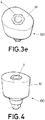
- Figure 3e shows a fifth step of this method.
- a biocompatible material is provided covering the space so that the custom body 61 is fixed to the pillar 4 in the dental abutment 100.
- FIG. 4 shows a final dental abutment 100 which has been manufactured according to a method described above.
- This dental abutment 100 comprises a dental abutment core 1 and a custom body 61.
- the custom body 61 may not rotate with respect to the dental abutment core 1 since the custom body 61 is now in connection with the anti-rotational means comprised in the dental abutment core 1.
Landscapes
- Health & Medical Sciences (AREA)
- Oral & Maxillofacial Surgery (AREA)
- Dentistry (AREA)
- Epidemiology (AREA)
- Life Sciences & Earth Sciences (AREA)
- Animal Behavior & Ethology (AREA)
- General Health & Medical Sciences (AREA)
- Public Health (AREA)
- Veterinary Medicine (AREA)
- Orthopedic Medicine & Surgery (AREA)
- Dental Prosthetics (AREA)
Claims (13)
- Dentalabutmentkern (1) zur Verwendung in einem Abutment zum Bilden des Zahnfleischgewebes um Implantate herum, wobei der Dentalabutmentkern (1) umfasst
eine prothetische Verbindung (2);
einen Pfeiler (4) umfassend Antirotationsmittel (431, 432) zum Verhindern, dass sich ein maßgeschneiderter Körper in Bezug auf den Dentalabutmentkern (1) dreht; und
eine Schulter (3), die sich zwischen der prothetischen Verbindung (2) und dem Pfeiler (4) befindet, wobei die Schulter (3) in Kontakt mit Zahnfleischgewebe sein soll und eine erste Basis (31) angrenzend bzw. benachbart zu der prothetischen Verbindung (2) und eine zweite Basis (32) gleich oder größer als die erste Basis (31) angrenzend bzw. benachbart zu dem Pfeiler (4) umfasst;
eine Kernachse (10) senkrecht zu der ersten Basis (31) und der zweiten Basis (32);
wobei
der Pfeiler (4) einen ersten Abschnitt (41) angrenzend bzw. benachbart zu der Schulter (3), einen zweiten Abschnitt (42) angrenzend bzw. benachbart zu dem ersten Abschnitt (41) und einen dritten Abschnitt (43) umfasst, der am weitesten von der Schulter (3) entfernt ist,
wobei ein Querschnitt von zumindest einem Teil des ersten Abschnitts (41) kreisförmig ist und einen Außendurchmesser aufweist, der geringer als eine Querschnittsabmessung des zweiten Abschnitts (42) ist, und wobei die Antirotationsmittel (431, 432) in dem dritten Abschnitt (43) enthalten bzw. umfasst sind,
dadurch gekennzeichnet, dass der erste Abschnitt (41) einen ersten Unterabschnitt (411) angrenzend bzw. benachbart zu der Schulter (3) und einen zweiten Unterabschnitt (412) mit einem kreisförmigen und geringerem Querschnitt als der Querschnitt des ersten Unterabschnitts (411) umfasst. - Dentalabutmentkern (1) nach Anspruch 1, wobei der zweite Abschnitt (42) ferner einen Vorsprung (421) umfasst.
- Dentalabutmentkern (1) nach Anspruch 2, wobei der Vorsprung (421) ein ringförmiger Vorsprung ist.
- Dentalabutmentkern (1) nach einem der Ansprüche 2 oder 3, wobei sich der Vorsprung (421) angrenzend bzw. benachbart zu dem ersten Abschnitt (41) des Pfeilers (4) befindet.
- Dentalabutmentkern (1) nach einem der vorhergehenden Ansprüche, wobei das Antirotationsmittel zumindest einen Schlitz (432) und einen Vorsprung (431) umfasst, der bzw. die gemäß der Kernachse (10) ausgerichtet ist bzw. sind.
- Nicht-intraorales Verfahren zum Fertigen eines Dentalabutments (100), umfassend die Schritte
Bereitstellen eines Dentalabutmentkerns (1) nach Anspruch 1;
Platzieren einer Kappe (5), die den zweiten Abschnitt (42) und den dritten Abschnitt (43) des Pfeilers (4) bedeckt;
Bereitstellen eines biokompatiblen Materials (6), so dass das biokompatible Material den ersten Abschnitt (41) des Pfeilers (4) erreicht, jedoch aufgrund der Zwischenanordnung der Kappe (5) nicht den zweiten Abschnitt (42) und den dritten Abschnitt (43) des Pfeilers (4) erreicht, so dass das biokompatible Material (6) ein maßgeschneiderter Körper (61) wird;
Entfernen der Kappe (5), so dass der zweite Abschnitt (42) und der dritte Abschnitt (43) des Pfeilers (4) von einem Raum (7) umgeben sind, in dem ein maßgeschneiderter Körper (61) fehlt;
Bereitstellen eines Materials, das den Raum (7) bedeckt, so dass der maßgeschneiderte Körper (61) an dem Pfeiler (4) befestigt bzw. fixiert ist. - Verfahren nach Anspruch 6, wobei der Dentalabutmentkern (1) in einer Formvorrichtung bereitgestellt wird und die Bereitstellung von biokompatiblem Material (6) durchgeführt wird, indem dieses biokompatible Material (6) in einem flüssigen Zustand in die Formvorrichtung gegossen wird und ferner das biokompatible Material (6) ausgehärtet wird, so dass es zu dem maßgeschneiderten Körper (61) wird.
- Verfahren nach einem der Ansprüche 6 oder 7, ferner umfassend den Schritt des Aufbringens eines Schmiermittels auf den ersten Abschnitt (41) des Pfeilers (4), bevor das biokompatible Material (6) eingegossen wird.
- Verfahren nach einem der Ansprüche 6 bis 8, wobei die Kappe (5) auf einem Vorsprung (421) des zweiten Abschnitts (42) des Pfeilers (4) ruht, wenn sie den dritten Abschnitt (43) des Pfeilers (4) bedeckend platziert wird bzw. ist.
- Verfahren nach einem der Ansprüche 6 bis 9, ferner umfassend den Schritt des Drehens des maßgeschneiderten Körpers (61), bis er eine optimale Position erreicht, bevor das Material zum Abdecken des Raums (7) bereitgestellt wird.
- Verfahren nach Anspruch 10, wobei der Schritt des Drehens des maßgeschneiderten Körpers (61) in einem Arbeitsdentalabguss bzw. -abdruck ausgeführt wird.
- Dentalwerkzeugsystem, das zum Ausführen der Schritte eines Verfahrens nach einem der Ansprüche 6 bis 8 geeignet ist, wobei das Dentalwerkzeugsystem umfasst
einen Dentalabutmentkern (1) nach einem der Ansprüche 1 bis 5;
eine Kappe (5), die geeignet ist, den zweiten Abschnitt (42) und den dritten Abschnitt (43) des Pfeilers (4) zu bedecken;
einen maßgeschneiderten Körper (61), der mit dem ersten Abschnitt (41) des Pfeilers (4) des Dentalabutmentkerns (1) gekoppelt ist. - Dentalwerkzeugsystem nach Anspruch 12, wobei der maßgeschneiderte Körper (61) eine Form aufweist, die im Allgemeinen dreieckig oder parallelogrammförmig oder rechteckig oder eiförmig oder kreisförmig ist.
Applications Claiming Priority (2)
| Application Number | Priority Date | Filing Date | Title |
|---|---|---|---|
| GR20170100383A GR20170100383A (el) | 2017-08-21 | 2017-08-21 | Πυρηνας οδοντικου κολοβωματος και μεθοδος για την κατασκευη ενος οδοντικου κολοβωματος |
| PCT/IB2018/055593 WO2019038610A1 (en) | 2017-08-21 | 2018-07-26 | DENTAL STOP ELEMENT CORE AND METHOD FOR MANUFACTURING DENTAL STOP MEMBER |
Publications (2)
| Publication Number | Publication Date |
|---|---|
| EP3672518A1 EP3672518A1 (de) | 2020-07-01 |
| EP3672518B1 true EP3672518B1 (de) | 2021-08-25 |
Family
ID=63364115
Family Applications (1)
| Application Number | Title | Priority Date | Filing Date |
|---|---|---|---|
| EP18759399.1A Active EP3672518B1 (de) | 2017-08-21 | 2018-07-26 | Kern eines dentalen abutments und verfahren zur herstellung eines dentalen abutments |
Country Status (5)
| Country | Link |
|---|---|
| US (1) | US11446122B2 (de) |
| EP (1) | EP3672518B1 (de) |
| CY (1) | CY1124581T1 (de) |
| GR (1) | GR20170100383A (de) |
| WO (1) | WO2019038610A1 (de) |
Families Citing this family (4)
| Publication number | Priority date | Publication date | Assignee | Title |
|---|---|---|---|---|
| WO2015189648A2 (en) | 2014-06-13 | 2015-12-17 | Vergoullis Ioannis | Abutments and impression posts for dental implant procedures |
| GR20170100383A (el) | 2017-08-21 | 2019-04-22 | Vp Innovato Holdings Ltd | Πυρηνας οδοντικου κολοβωματος και μεθοδος για την κατασκευη ενος οδοντικου κολοβωματος |
| GR20200100312A (el) | 2020-06-04 | 2022-01-13 | Ιωαννης Αντωνιου Βεργουλλης | Συστημα αξονων σαρωσης και μεθοδος |
| GR1010564B (el) * | 2023-05-16 | 2023-10-31 | Vp Innovato Holdings Ltd, | Μεσοφασικο κολοβωμα για την υποστηριξη προσθετικης εργασιας |
Family Cites Families (78)
| Publication number | Priority date | Publication date | Assignee | Title |
|---|---|---|---|---|
| US512840A (en) | 1894-01-16 | Dental mold for teeth | ||
| US5180303A (en) | 1988-09-21 | 1993-01-19 | Regents Of The University Of California | Retrievable dental prothesis apparatus and method of fabrication |
| US5183053A (en) | 1991-04-12 | 1993-02-02 | Acuderm, Inc. | Elliptical biopsy punch |
| US5338196A (en) | 1993-04-08 | 1994-08-16 | Implant Innovations, Inc. | Dental laboratory components and procedures for anatomical restoration on artificial root fixtures |
| NL9301308A (nl) | 1993-07-26 | 1995-02-16 | Willem Frederick Van Nifterick | Werkwijze voor het vastzetten van een tandprothese op implantaten in het kaakbeen van een patiënt en middel te gebruiken daarbij. |
| US5492471A (en) | 1994-03-23 | 1996-02-20 | Gary Singer | Healing cap system |
| US5499918A (en) | 1994-08-22 | 1996-03-19 | Diro, Inc. | Apparatus for preserving interdental papilla and method for using |
| JPH08196549A (ja) | 1995-01-26 | 1996-08-06 | Nakanishi:Kk | 歯肉切除器および歯肉切除装置 |
| US5984682A (en) | 1996-01-11 | 1999-11-16 | Carlson; Ronald S. | Immediate, laminated light cured direct composite bridge and method |
| JP2000506037A (ja) | 1996-02-29 | 2000-05-23 | インプラント・イノヴェーションズ・インコーポレーテッド | 単一の歯の歯修復システム |
| US5759036A (en) | 1996-07-29 | 1998-06-02 | Hinds; Kenneth F. | Complete dental implant system and method |
| US6540514B1 (en) | 1998-02-26 | 2003-04-01 | Theodore S. Falk | Method for isolating a dental implant |
| US6159010A (en) * | 1998-04-23 | 2000-12-12 | Implant Innovations, Inc. | Fenestrated dental coping |
| US6672871B2 (en) | 2000-06-19 | 2004-01-06 | Nobel Biocare Ab | Coping with standoffs |
| AU2001291278A1 (en) | 2000-08-30 | 2002-03-13 | Nobel Biocare Ab | Impression cap |
| US6386876B1 (en) | 2000-11-29 | 2002-05-14 | Kenneth K. S. Lee | Universal tissue emergence profile shaping healing abutment, provisional and restoration abutments, impression coping and ceramic crown base system |
| US7204692B2 (en) | 2002-03-13 | 2007-04-17 | Lifecore Biomedical, Inc. | Impression cap |
| DE102004035091B4 (de) | 2004-07-20 | 2017-10-26 | Sirona Dental Systems Gmbh | Verfahren zur Bestimmung der Lage und Orientierung der Achse eines direkt im Patientenmund befindlichen dentalen Implantats sowie Aufsatzteil hierfür |
| ES2361123T3 (es) | 2007-01-18 | 2011-06-14 | Straumann Holding Ag | Funda de impresión. |
| GB0707285D0 (en) | 2007-04-17 | 2007-05-23 | Burke John | Implantable apparatus for modulation of skeletal growth |
| EP2130513A1 (de) | 2008-06-06 | 2009-12-09 | Straumann Holding AG | Vorrichtung zum Anbringen einer Abformkappe an einem Zahnimplantat |
| US8083522B2 (en) | 2008-10-29 | 2011-12-27 | Inpronto Inc. | Method for tooth implants |
| US20100209877A1 (en) | 2009-02-13 | 2010-08-19 | Stephen Hogan | Components for use with implants and related methods |
| US20100196849A1 (en) | 2008-12-22 | 2010-08-05 | Esynapse Corp. | Flapless dental implant punch |
| JP4896176B2 (ja) | 2009-04-16 | 2012-03-14 | 寶▲玉▼生技股▲分▼有限公司 | アバットメントアセンブリ |
| US9539068B2 (en) | 2009-07-24 | 2017-01-10 | Warsaw Orthopedic, Inc. | Implantable screw and system for socket preservation |
| KR100981463B1 (ko) | 2010-01-12 | 2010-09-10 | 라파바이오 주식회사 | 맞춤형 제작을 위한 임플란트용 어버트먼트 소재 및 이를 이용한 맞춤형 어버트먼트 제조 방법 |
| US20110200968A1 (en) | 2010-02-17 | 2011-08-18 | Procerex Dental Lab Llc | System and method for fabricating a dental healing abutment |
| KR101035503B1 (ko) | 2010-03-19 | 2011-05-20 | 변태희 | 맞춤형 어버트먼트 가공용 자재 |
| MX2010004033A (es) | 2010-04-14 | 2011-10-28 | Guadalupe Enrique Meneses Jimenez | Aditamento protesico para anclaje en hueso. |
| ES2477288T3 (es) | 2010-12-07 | 2014-07-16 | Biomet 3I, Llc | Elemento de exploración universal para su uso en un implante dental y en análogos de implante dental |
| US9433480B2 (en) * | 2010-12-21 | 2016-09-06 | Zimmer Dental, Inc. | Implant with porous sleeve including anti-rotation features |
| US8382477B2 (en) | 2011-04-18 | 2013-02-26 | Terry B. Philibin | Healing abutment system for bone contouring |
| AU2012255865B8 (en) | 2011-05-16 | 2015-06-04 | Biomet 3I, Llc | Temporary abutment with combination of scanning features and provisionalization features |
| US20130196290A1 (en) | 2011-05-16 | 2013-08-01 | Biomet 3I, Llc | Healing Abutment Assembly With Combination Of Scanning Features |
| US20140100327A1 (en) | 2011-05-24 | 2014-04-10 | Sumitomo Seika Chemicals Co., Ltd. | (meth)acrylic acid-based copolymer |
| DE102011053336A1 (de) | 2011-09-07 | 2013-03-07 | Bredent Gmbh & Co. Kg | Anordnung und Verfahren zur Gewinnung von intraoralen Scandaten und Abutment hierfür |
| WO2013046040A2 (en) | 2011-09-30 | 2013-04-04 | Adi Mashiach | Apparatus and method for controlling energy delivery as a function of degree of coupling |
| US8628327B1 (en) | 2012-10-02 | 2014-01-14 | Mark H. Blaisdell | Casting jig for chair-side manufacture of customizable sculptable anatomical healing caps |
| US9572640B2 (en) | 2012-10-02 | 2017-02-21 | Mark H. Blaisdell | Casting jig for chair-side manufacture of customizable sculptable anatomical healing caps |
| US9895209B2 (en) | 2012-01-10 | 2018-02-20 | Mark H. Blaisdell | Casting jig including elongate handle for chair-side manufacture of customizable sculptable anatomical healing caps, and method for forming bis-acrylic crown |
| US20130177872A1 (en) | 2012-01-10 | 2013-07-11 | Mark H. Blaisdell | Customizable sculptable anatomical healing caps, systems, and related methods |
| US10507081B2 (en) | 2012-01-10 | 2019-12-17 | Esthetic Implant Solutions, Llc | Methods for taking an impression or scanning without requiring removal of a temporary healing abutment |
| US20130203015A1 (en) | 2012-01-17 | 2013-08-08 | James Falco | Gingival tissue contour device |
| TWI657805B (zh) | 2012-05-10 | 2019-05-01 | 賽德荷姆央H | 用於拔牙傷口重建之牙科裝置 |
| GB2502328A (en) | 2012-05-24 | 2013-11-27 | Nobel Biocare Services Ag | A dental implant moulded with a through hole |
| US20140080092A1 (en) | 2012-09-14 | 2014-03-20 | Biomet 3I, Llc | Temporary dental prosthesis for use in developing final dental prosthesis |
| TW201318604A (zh) | 2012-11-14 | 2013-05-16 | Chen Yi Lin | 口內取模套件與口內取模方法 |
| DE102013100529A1 (de) * | 2013-01-18 | 2014-07-24 | Bredent Gmbh & Co. Kg | Verankerungselement und Verfahren zur Herstellung |
| DE102013101511A1 (de) | 2013-02-15 | 2014-08-21 | Bredent Gmbh & Co. Kg | Zahnprothetische Anordnung und zahnprothetisches System |
| KR101446064B1 (ko) | 2013-05-07 | 2014-10-01 | 라파바이오 주식회사 | 즉시 보철물 제작이 가능한 치과 임플란트 수술용 가이드 및 그 활용 방법 |
| KR101419519B1 (ko) | 2013-10-10 | 2014-08-13 | (주)교보테크 | 임플란트 어셈블리 |
| CN203609529U (zh) * | 2013-11-18 | 2014-05-28 | 大连三生科技发展有限公司 | 一种易取出的种植体装置及其旋出工具 |
| CN103550003B (zh) * | 2013-11-18 | 2015-12-23 | 大连三生科技发展有限公司 | 易取出的种植体装置及其旋出工具 |
| CN103550006B (zh) * | 2013-11-18 | 2016-08-31 | 大连三生科技发展有限公司 | 抗旋转种植体装置 |
| CN203555848U (zh) * | 2013-11-18 | 2014-04-23 | 大连三生科技发展有限公司 | 一种抗旋转种植体装置 |
| EP3094283A4 (de) | 2013-12-20 | 2018-01-24 | Biomet 3i, LLC | Zahnärztliches system zur entwicklung von angepassten prothesen durch abtasten von codierten elementen |
| KR101495480B1 (ko) * | 2014-05-14 | 2015-03-25 | 최종훈 | 링크 어버트먼트 커넥터 |
| EP3583909B1 (de) * | 2014-05-27 | 2021-05-19 | Ivoclar Vivadent AG | Verfahren zur erzeugung eines zahnersatzes |
| GR20150100111A (el) * | 2015-03-12 | 2016-10-20 | Ιωαννης Αντωνιου Βεργουλλης | Ευθεια και κεκλιμενα εξατομικευμενα με δυνατοτητα τροποποιησης κολοβωματα κι ευθεις και κεκλιμενοι εξατομικευμενοι με δυνατοτητα τροποποιησης στυλοι αποτυπωσης οδοντικων εμφυτευματων και μητρες μαζικης παραγωγης τους |
| WO2015189648A2 (en) | 2014-06-13 | 2015-12-17 | Vergoullis Ioannis | Abutments and impression posts for dental implant procedures |
| GR1008855B (el) * | 2014-12-16 | 2016-09-27 | Ιωαννης Αντωνιου Βεργουλλης | Εξατομικευσιμοι στυλοι αποτυπωσης, ανοικτου τυπου ευθεις και κλειστου τυπου, ευθεις και κεκλιμενοι κι ανεξαρτητα εξαρτηματα υλοποιησης και επαληθευσης της διαδικασιας αποτυπωσης οδοντικων εμφυτευματων |
| US9610143B2 (en) | 2014-06-19 | 2017-04-04 | Osteolife Biomedical, Llc | Compressed decalcified trabecular bone grafts and tooth socket repair |
| KR20160006385A (ko) | 2014-07-09 | 2016-01-19 | (주)예스바이오테크 | 스캔바디 기능을 구비한 힐링어버트먼트 |
| FR3027792B1 (fr) | 2014-10-29 | 2021-01-22 | Armand Stemmer | Element de cicatrisation pour une restauration dentaire |
| FR3031667B1 (fr) | 2015-01-16 | 2020-12-11 | Poly Shape | Procede de fabrication d'un pilier de prothese dentaire, dispositif et machine pour mettre en oeuvre le procede et pilier obtenu par le procede |
| US10779960B2 (en) | 2015-02-27 | 2020-09-22 | In2Bones Usa, Llc | Engineered sterile cartilage allograft implant plug with sterile, specific instrument kit(s) |
| WO2017029670A1 (en) | 2015-08-17 | 2017-02-23 | Optical Metrology Ltd. | Intra-oral mapping of edentulous or partially edentulous mouth cavities |
| FR3042699B1 (fr) | 2015-10-27 | 2021-02-19 | Euroteknika | Element de cicatrisation pour une restauration dentaire |
| KR101734706B1 (ko) | 2015-11-12 | 2017-05-11 | 최정일 | 진지바와 치은형성캡의 분리형 디지털 힐링 어버트먼트 장치 |
| EP3474772B1 (de) | 2016-06-24 | 2020-04-22 | VP Innovato Holdings Ltd. | Dentalwerkzeugsystem und -verfahren |
| DE102016213399A1 (de) | 2016-07-21 | 2018-01-25 | Sirona Dental Systems Gmbh | Vermessungssystem und Verfahren zur Vermessung einer Implantat-Implantat-Situation |
| TWI615133B (zh) | 2016-08-01 | 2018-02-21 | 千鐿生醫科技股份有限公司 | 癒合帽、癒合帽組件及其選擇方法 |
| IL248179A0 (en) | 2016-10-05 | 2017-01-31 | Mis Implants Tech Ltd | Scanning column, bite upright, and related method for documenting dental implant placement |
| CN110430838B (zh) | 2016-12-08 | 2022-03-08 | 王茜 | 一种具有完整胶原蛋白外壳的骨移植塞及其制备方法 |
| GR20170100383A (el) | 2017-08-21 | 2019-04-22 | Vp Innovato Holdings Ltd | Πυρηνας οδοντικου κολοβωματος και μεθοδος για την κατασκευη ενος οδοντικου κολοβωματος |
| GR1009730B (el) | 2018-08-31 | 2020-05-15 | Vp Innovato Holdings Ltd | Αξονες ψηφιακης αποτυπωσης με σαρωση και μεθοδολογια |
| GR20190100040A (el) | 2019-01-24 | 2020-08-31 | Vp Innovato Holdings Ltd | Συστημα ταπων διατηρησης του μετεξακτικου φατνιου και χρηση |
-
2017
- 2017-08-21 GR GR20170100383A patent/GR20170100383A/el unknown
-
2018
- 2018-07-26 EP EP18759399.1A patent/EP3672518B1/de active Active
- 2018-07-26 WO PCT/IB2018/055593 patent/WO2019038610A1/en not_active Ceased
- 2018-07-26 US US16/626,852 patent/US11446122B2/en active Active
-
2021
- 2021-10-13 CY CY20211100883T patent/CY1124581T1/el unknown
Also Published As
| Publication number | Publication date |
|---|---|
| WO2019038610A1 (en) | 2019-02-28 |
| GR20170100383A (el) | 2019-04-22 |
| EP3672518A1 (de) | 2020-07-01 |
| US11446122B2 (en) | 2022-09-20 |
| US20200222155A1 (en) | 2020-07-16 |
| CY1124581T1 (el) | 2022-07-22 |
Similar Documents
| Publication | Publication Date | Title |
|---|---|---|
| EP3672518B1 (de) | Kern eines dentalen abutments und verfahren zur herstellung eines dentalen abutments | |
| EP1651132B1 (de) | Kit zur bereitstellung von dentalem aufbaupfosten | |
| KR102302292B1 (ko) | 맞춤형 치과용 임플란트 어버트먼트 및 임프레션 포스트 용 몰드 | |
| US6974322B2 (en) | Implant-supported dental prosthesis and a process for its production | |
| EP2025302B1 (de) | Ein Zahnsystem für ein Verfahren zum Formen einer Zahnprothese | |
| CA2833215C (en) | Temporary abutment with combination of scanning features and provisionalization features | |
| EP1039840A1 (de) | Zahnmedizinisches implantatsystem und verfahren | |
| EP3443932B1 (de) | Stegherstellungs- und zahnprothesenreferenz- und -registrierungssystem | |
| KR102080241B1 (ko) | 임플란트용 실린더장치 | |
| CN109069236A (zh) | 牙科修复体的牙科部件和用于装配牙科部件的方法 | |
| EP1704829B1 (de) | Abutmenset für ein Zahnimplantat und Herstellungsverfahren einer Zahnprothese | |
| KR20160087707A (ko) | 3차원 스캔 데이터 추출을 위한 임플란트용 어버트먼트 및 이를 이용한 임플란트 시술방법 | |
| CN113208756B (zh) | 一种用于多单位种植基台转移和精确取模方法 | |
| CN102686183A (zh) | 用于微型植入装置固定/移动口腔修复应用的假体安装设备和搬运工具 | |
| CN110731825B (zh) | 一种刚性连接杆组件及其使用方法 | |
| KR102510423B1 (ko) | 디지털 오버덴쳐 제조방법 | |
| KR20230033134A (ko) | 디지털 오버덴쳐의 제조방법 | |
| US20100233656A1 (en) | Dual function system for dental implants | |
| KR101120680B1 (ko) | 임플란트용 조립체 | |
| KR101277505B1 (ko) | 맞춤형 어버트먼트 지그 및 그 제조방법 | |
| KR20230033133A (ko) | 디지털 오버덴쳐의 제조방법 | |
| WO2005107628A1 (en) | Placement of orthodontic brackets | |
| IL173202A (en) | Method and kit for preparing a dental abutment | |
| HK1144899A (en) | Dual-function system for dental implants | |
| HK1203801A1 (en) | Dental post for supporting dental prostheses, and method for the production thereof |
Legal Events
| Date | Code | Title | Description |
|---|---|---|---|
| STAA | Information on the status of an ep patent application or granted ep patent |
Free format text: STATUS: UNKNOWN |
|
| STAA | Information on the status of an ep patent application or granted ep patent |
Free format text: STATUS: THE INTERNATIONAL PUBLICATION HAS BEEN MADE |
|
| PUAI | Public reference made under article 153(3) epc to a published international application that has entered the european phase |
Free format text: ORIGINAL CODE: 0009012 |
|
| STAA | Information on the status of an ep patent application or granted ep patent |
Free format text: STATUS: REQUEST FOR EXAMINATION WAS MADE |
|
| 17P | Request for examination filed |
Effective date: 20200120 |
|
| AK | Designated contracting states |
Kind code of ref document: A1 Designated state(s): AL AT BE BG CH CY CZ DE DK EE ES FI FR GB GR HR HU IE IS IT LI LT LU LV MC MK MT NL NO PL PT RO RS SE SI SK SM TR |
|
| AX | Request for extension of the european patent |
Extension state: BA ME |
|
| DAV | Request for validation of the european patent (deleted) | ||
| DAX | Request for extension of the european patent (deleted) | ||
| RAP1 | Party data changed (applicant data changed or rights of an application transferred) |
Owner name: VP INNOVATO HOLDINGS LTD |
|
| GRAP | Despatch of communication of intention to grant a patent |
Free format text: ORIGINAL CODE: EPIDOSNIGR1 |
|
| STAA | Information on the status of an ep patent application or granted ep patent |
Free format text: STATUS: GRANT OF PATENT IS INTENDED |
|
| INTG | Intention to grant announced |
Effective date: 20210219 |
|
| GRAS | Grant fee paid |
Free format text: ORIGINAL CODE: EPIDOSNIGR3 |
|
| GRAA | (expected) grant |
Free format text: ORIGINAL CODE: 0009210 |
|
| STAA | Information on the status of an ep patent application or granted ep patent |
Free format text: STATUS: THE PATENT HAS BEEN GRANTED |
|
| AK | Designated contracting states |
Kind code of ref document: B1 Designated state(s): AL AT BE BG CH CY CZ DE DK EE ES FI FR GB GR HR HU IE IS IT LI LT LU LV MC MK MT NL NO PL PT RO RS SE SI SK SM TR |
|
| REG | Reference to a national code |
Ref country code: CH Ref legal event code: EP |
|
| REG | Reference to a national code |
Ref country code: IE Ref legal event code: FG4D Ref country code: AT Ref legal event code: REF Ref document number: 1423006 Country of ref document: AT Kind code of ref document: T Effective date: 20210915 |
|
| REG | Reference to a national code |
Ref country code: DE Ref legal event code: R096 Ref document number: 602018022494 Country of ref document: DE |
|
| REG | Reference to a national code |
Ref country code: GR Ref legal event code: EP Ref document number: 20210402726 Country of ref document: GR Effective date: 20211111 |
|
| REG | Reference to a national code |
Ref country code: LT Ref legal event code: MG9D |
|
| REG | Reference to a national code |
Ref country code: NL Ref legal event code: MP Effective date: 20210825 |
|
| REG | Reference to a national code |
Ref country code: AT Ref legal event code: MK05 Ref document number: 1423006 Country of ref document: AT Kind code of ref document: T Effective date: 20210825 |
|
| PG25 | Lapsed in a contracting state [announced via postgrant information from national office to epo] |
Ref country code: SE Free format text: LAPSE BECAUSE OF FAILURE TO SUBMIT A TRANSLATION OF THE DESCRIPTION OR TO PAY THE FEE WITHIN THE PRESCRIBED TIME-LIMIT Effective date: 20210825 Ref country code: RS Free format text: LAPSE BECAUSE OF FAILURE TO SUBMIT A TRANSLATION OF THE DESCRIPTION OR TO PAY THE FEE WITHIN THE PRESCRIBED TIME-LIMIT Effective date: 20210825 Ref country code: HR Free format text: LAPSE BECAUSE OF FAILURE TO SUBMIT A TRANSLATION OF THE DESCRIPTION OR TO PAY THE FEE WITHIN THE PRESCRIBED TIME-LIMIT Effective date: 20210825 Ref country code: FI Free format text: LAPSE BECAUSE OF FAILURE TO SUBMIT A TRANSLATION OF THE DESCRIPTION OR TO PAY THE FEE WITHIN THE PRESCRIBED TIME-LIMIT Effective date: 20210825 Ref country code: ES Free format text: LAPSE BECAUSE OF FAILURE TO SUBMIT A TRANSLATION OF THE DESCRIPTION OR TO PAY THE FEE WITHIN THE PRESCRIBED TIME-LIMIT Effective date: 20210825 Ref country code: PT Free format text: LAPSE BECAUSE OF FAILURE TO SUBMIT A TRANSLATION OF THE DESCRIPTION OR TO PAY THE FEE WITHIN THE PRESCRIBED TIME-LIMIT Effective date: 20211227 Ref country code: NO Free format text: LAPSE BECAUSE OF FAILURE TO SUBMIT A TRANSLATION OF THE DESCRIPTION OR TO PAY THE FEE WITHIN THE PRESCRIBED TIME-LIMIT Effective date: 20211125 Ref country code: LT Free format text: LAPSE BECAUSE OF FAILURE TO SUBMIT A TRANSLATION OF THE DESCRIPTION OR TO PAY THE FEE WITHIN THE PRESCRIBED TIME-LIMIT Effective date: 20210825 Ref country code: AT Free format text: LAPSE BECAUSE OF FAILURE TO SUBMIT A TRANSLATION OF THE DESCRIPTION OR TO PAY THE FEE WITHIN THE PRESCRIBED TIME-LIMIT Effective date: 20210825 Ref country code: BG Free format text: LAPSE BECAUSE OF FAILURE TO SUBMIT A TRANSLATION OF THE DESCRIPTION OR TO PAY THE FEE WITHIN THE PRESCRIBED TIME-LIMIT Effective date: 20211125 |
|
| PG25 | Lapsed in a contracting state [announced via postgrant information from national office to epo] |
Ref country code: PL Free format text: LAPSE BECAUSE OF FAILURE TO SUBMIT A TRANSLATION OF THE DESCRIPTION OR TO PAY THE FEE WITHIN THE PRESCRIBED TIME-LIMIT Effective date: 20210825 Ref country code: LV Free format text: LAPSE BECAUSE OF FAILURE TO SUBMIT A TRANSLATION OF THE DESCRIPTION OR TO PAY THE FEE WITHIN THE PRESCRIBED TIME-LIMIT Effective date: 20210825 |
|
| PG25 | Lapsed in a contracting state [announced via postgrant information from national office to epo] |
Ref country code: NL Free format text: LAPSE BECAUSE OF FAILURE TO SUBMIT A TRANSLATION OF THE DESCRIPTION OR TO PAY THE FEE WITHIN THE PRESCRIBED TIME-LIMIT Effective date: 20210825 |
|
| PG25 | Lapsed in a contracting state [announced via postgrant information from national office to epo] |
Ref country code: DK Free format text: LAPSE BECAUSE OF FAILURE TO SUBMIT A TRANSLATION OF THE DESCRIPTION OR TO PAY THE FEE WITHIN THE PRESCRIBED TIME-LIMIT Effective date: 20210825 |
|
| REG | Reference to a national code |
Ref country code: DE Ref legal event code: R097 Ref document number: 602018022494 Country of ref document: DE |
|
| PG25 | Lapsed in a contracting state [announced via postgrant information from national office to epo] |
Ref country code: SM Free format text: LAPSE BECAUSE OF FAILURE TO SUBMIT A TRANSLATION OF THE DESCRIPTION OR TO PAY THE FEE WITHIN THE PRESCRIBED TIME-LIMIT Effective date: 20210825 Ref country code: SK Free format text: LAPSE BECAUSE OF FAILURE TO SUBMIT A TRANSLATION OF THE DESCRIPTION OR TO PAY THE FEE WITHIN THE PRESCRIBED TIME-LIMIT Effective date: 20210825 Ref country code: RO Free format text: LAPSE BECAUSE OF FAILURE TO SUBMIT A TRANSLATION OF THE DESCRIPTION OR TO PAY THE FEE WITHIN THE PRESCRIBED TIME-LIMIT Effective date: 20210825 Ref country code: EE Free format text: LAPSE BECAUSE OF FAILURE TO SUBMIT A TRANSLATION OF THE DESCRIPTION OR TO PAY THE FEE WITHIN THE PRESCRIBED TIME-LIMIT Effective date: 20210825 Ref country code: CZ Free format text: LAPSE BECAUSE OF FAILURE TO SUBMIT A TRANSLATION OF THE DESCRIPTION OR TO PAY THE FEE WITHIN THE PRESCRIBED TIME-LIMIT Effective date: 20210825 Ref country code: AL Free format text: LAPSE BECAUSE OF FAILURE TO SUBMIT A TRANSLATION OF THE DESCRIPTION OR TO PAY THE FEE WITHIN THE PRESCRIBED TIME-LIMIT Effective date: 20210825 |
|
| PLBE | No opposition filed within time limit |
Free format text: ORIGINAL CODE: 0009261 |
|
| STAA | Information on the status of an ep patent application or granted ep patent |
Free format text: STATUS: NO OPPOSITION FILED WITHIN TIME LIMIT |
|
| PG25 | Lapsed in a contracting state [announced via postgrant information from national office to epo] |
Ref country code: IT Free format text: LAPSE BECAUSE OF FAILURE TO SUBMIT A TRANSLATION OF THE DESCRIPTION OR TO PAY THE FEE WITHIN THE PRESCRIBED TIME-LIMIT Effective date: 20210825 |
|
| 26N | No opposition filed |
Effective date: 20220527 |
|
| PG25 | Lapsed in a contracting state [announced via postgrant information from national office to epo] |
Ref country code: SI Free format text: LAPSE BECAUSE OF FAILURE TO SUBMIT A TRANSLATION OF THE DESCRIPTION OR TO PAY THE FEE WITHIN THE PRESCRIBED TIME-LIMIT Effective date: 20210825 |
|
| PG25 | Lapsed in a contracting state [announced via postgrant information from national office to epo] |
Ref country code: MC Free format text: LAPSE BECAUSE OF FAILURE TO SUBMIT A TRANSLATION OF THE DESCRIPTION OR TO PAY THE FEE WITHIN THE PRESCRIBED TIME-LIMIT Effective date: 20210825 |
|
| REG | Reference to a national code |
Ref country code: BE Ref legal event code: MM Effective date: 20220731 |
|
| PG25 | Lapsed in a contracting state [announced via postgrant information from national office to epo] |
Ref country code: LU Free format text: LAPSE BECAUSE OF NON-PAYMENT OF DUE FEES Effective date: 20220726 |
|
| PG25 | Lapsed in a contracting state [announced via postgrant information from national office to epo] |
Ref country code: BE Free format text: LAPSE BECAUSE OF NON-PAYMENT OF DUE FEES Effective date: 20220731 |
|
| P01 | Opt-out of the competence of the unified patent court (upc) registered |
Effective date: 20230323 |
|
| PG25 | Lapsed in a contracting state [announced via postgrant information from national office to epo] |
Ref country code: IE Free format text: LAPSE BECAUSE OF NON-PAYMENT OF DUE FEES Effective date: 20220726 |
|
| PG25 | Lapsed in a contracting state [announced via postgrant information from national office to epo] |
Ref country code: MK Free format text: LAPSE BECAUSE OF FAILURE TO SUBMIT A TRANSLATION OF THE DESCRIPTION OR TO PAY THE FEE WITHIN THE PRESCRIBED TIME-LIMIT Effective date: 20210825 |
|
| PG25 | Lapsed in a contracting state [announced via postgrant information from national office to epo] |
Ref country code: HU Free format text: LAPSE BECAUSE OF FAILURE TO SUBMIT A TRANSLATION OF THE DESCRIPTION OR TO PAY THE FEE WITHIN THE PRESCRIBED TIME-LIMIT; INVALID AB INITIO Effective date: 20180726 |
|
| PGFP | Annual fee paid to national office [announced via postgrant information from national office to epo] |
Ref country code: GR Payment date: 20240409 Year of fee payment: 7 |
|
| PG25 | Lapsed in a contracting state [announced via postgrant information from national office to epo] |
Ref country code: MT Free format text: LAPSE BECAUSE OF FAILURE TO SUBMIT A TRANSLATION OF THE DESCRIPTION OR TO PAY THE FEE WITHIN THE PRESCRIBED TIME-LIMIT Effective date: 20210825 |
|
| PGFP | Annual fee paid to national office [announced via postgrant information from national office to epo] |
Ref country code: DE Payment date: 20240712 Year of fee payment: 7 |
|
| PGFP | Annual fee paid to national office [announced via postgrant information from national office to epo] |
Ref country code: GB Payment date: 20240729 Year of fee payment: 7 |
|
| PGFP | Annual fee paid to national office [announced via postgrant information from national office to epo] |
Ref country code: FR Payment date: 20240725 Year of fee payment: 7 |
|
| PGFP | Annual fee paid to national office [announced via postgrant information from national office to epo] |
Ref country code: CH Payment date: 20240805 Year of fee payment: 7 |
|
| PGFP | Annual fee paid to national office [announced via postgrant information from national office to epo] |
Ref country code: CY Payment date: 20240408 Year of fee payment: 7 |
|
| PG25 | Lapsed in a contracting state [announced via postgrant information from national office to epo] |
Ref country code: TR Free format text: LAPSE BECAUSE OF FAILURE TO SUBMIT A TRANSLATION OF THE DESCRIPTION OR TO PAY THE FEE WITHIN THE PRESCRIBED TIME-LIMIT Effective date: 20210825 |
|
| REG | Reference to a national code |
Ref country code: DE Ref legal event code: R119 Ref document number: 602018022494 Country of ref document: DE |
|
| REG | Reference to a national code |
Ref country code: CH Ref legal event code: H13 Free format text: ST27 STATUS EVENT CODE: U-0-0-H10-H13 (AS PROVIDED BY THE NATIONAL OFFICE) Effective date: 20260224 |
|
| GBPC | Gb: european patent ceased through non-payment of renewal fee |
Effective date: 20250726 |
|
| PG25 | Lapsed in a contracting state [announced via postgrant information from national office to epo] |
Ref country code: GB Free format text: LAPSE BECAUSE OF NON-PAYMENT OF DUE FEES Effective date: 20250726 |
|
| PG25 | Lapsed in a contracting state [announced via postgrant information from national office to epo] |
Ref country code: DE Free format text: LAPSE BECAUSE OF NON-PAYMENT OF DUE FEES Effective date: 20260203 |
|
| PG25 | Lapsed in a contracting state [announced via postgrant information from national office to epo] |
Ref country code: FR Free format text: LAPSE BECAUSE OF NON-PAYMENT OF DUE FEES Effective date: 20250731 |
|
| PG25 | Lapsed in a contracting state [announced via postgrant information from national office to epo] |
Ref country code: CH Free format text: LAPSE BECAUSE OF NON-PAYMENT OF DUE FEES Effective date: 20250731 |
|
| PG25 | Lapsed in a contracting state [announced via postgrant information from national office to epo] |
Ref country code: CY Free format text: LAPSE BECAUSE OF NON-PAYMENT OF DUE FEES Effective date: 20250726 Ref country code: GR Free format text: LAPSE BECAUSE OF NON-PAYMENT OF DUE FEES Effective date: 20260204 |