EP3672335A1 - Verfahren und vorrichtung zur inbetriebnahme eines beleuchtungssystems - Google Patents
Verfahren und vorrichtung zur inbetriebnahme eines beleuchtungssystems Download PDFInfo
- Publication number
- EP3672335A1 EP3672335A1 EP19214798.1A EP19214798A EP3672335A1 EP 3672335 A1 EP3672335 A1 EP 3672335A1 EP 19214798 A EP19214798 A EP 19214798A EP 3672335 A1 EP3672335 A1 EP 3672335A1
- Authority
- EP
- European Patent Office
- Prior art keywords
- dataset
- lighting
- lighting fixtures
- probability
- location
- Prior art date
- Legal status (The legal status is an assumption and is not a legal conclusion. Google has not performed a legal analysis and makes no representation as to the accuracy of the status listed.)
- Granted
Links
- 238000000034 method Methods 0.000 title claims abstract description 54
- 238000001514 detection method Methods 0.000 claims abstract description 70
- 238000012545 processing Methods 0.000 claims abstract description 27
- 238000013507 mapping Methods 0.000 claims description 20
- 238000005259 measurement Methods 0.000 claims description 6
- 230000001174 ascending effect Effects 0.000 claims description 5
- 238000004590 computer program Methods 0.000 claims description 5
- 238000012935 Averaging Methods 0.000 claims description 4
- 230000009467 reduction Effects 0.000 abstract description 4
- 239000013598 vector Substances 0.000 description 32
- 230000000875 corresponding effect Effects 0.000 description 8
- 230000008569 process Effects 0.000 description 7
- 230000015654 memory Effects 0.000 description 3
- 230000003287 optical effect Effects 0.000 description 3
- 238000004891 communication Methods 0.000 description 2
- 230000003247 decreasing effect Effects 0.000 description 2
- 230000001419 dependent effect Effects 0.000 description 2
- 238000010586 diagram Methods 0.000 description 2
- 238000009434 installation Methods 0.000 description 2
- 230000008901 benefit Effects 0.000 description 1
- 230000005540 biological transmission Effects 0.000 description 1
- 238000010276 construction Methods 0.000 description 1
- 230000001276 controlling effect Effects 0.000 description 1
- 230000002596 correlated effect Effects 0.000 description 1
- 238000013461 design Methods 0.000 description 1
- 230000001627 detrimental effect Effects 0.000 description 1
- 230000006870 function Effects 0.000 description 1
- 230000003993 interaction Effects 0.000 description 1
- 239000011159 matrix material Substances 0.000 description 1
- 238000007781 pre-processing Methods 0.000 description 1
- 238000012360 testing method Methods 0.000 description 1
- 238000010200 validation analysis Methods 0.000 description 1
Images


Classifications
-
- H—ELECTRICITY
- H05—ELECTRIC TECHNIQUES NOT OTHERWISE PROVIDED FOR
- H05B—ELECTRIC HEATING; ELECTRIC LIGHT SOURCES NOT OTHERWISE PROVIDED FOR; CIRCUIT ARRANGEMENTS FOR ELECTRIC LIGHT SOURCES, IN GENERAL
- H05B47/00—Circuit arrangements for operating light sources in general, i.e. where the type of light source is not relevant
- H05B47/10—Controlling the light source
- H05B47/175—Controlling the light source by remote control
- H05B47/19—Controlling the light source by remote control via wireless transmission
-
- H—ELECTRICITY
- H05—ELECTRIC TECHNIQUES NOT OTHERWISE PROVIDED FOR
- H05B—ELECTRIC HEATING; ELECTRIC LIGHT SOURCES NOT OTHERWISE PROVIDED FOR; CIRCUIT ARRANGEMENTS FOR ELECTRIC LIGHT SOURCES, IN GENERAL
- H05B47/00—Circuit arrangements for operating light sources in general, i.e. where the type of light source is not relevant
- H05B47/10—Controlling the light source
- H05B47/105—Controlling the light source in response to determined parameters
-
- H—ELECTRICITY
- H05—ELECTRIC TECHNIQUES NOT OTHERWISE PROVIDED FOR
- H05B—ELECTRIC HEATING; ELECTRIC LIGHT SOURCES NOT OTHERWISE PROVIDED FOR; CIRCUIT ARRANGEMENTS FOR ELECTRIC LIGHT SOURCES, IN GENERAL
- H05B47/00—Circuit arrangements for operating light sources in general, i.e. where the type of light source is not relevant
- H05B47/10—Controlling the light source
- H05B47/155—Coordinated control of two or more light sources
-
- H—ELECTRICITY
- H05—ELECTRIC TECHNIQUES NOT OTHERWISE PROVIDED FOR
- H05B—ELECTRIC HEATING; ELECTRIC LIGHT SOURCES NOT OTHERWISE PROVIDED FOR; CIRCUIT ARRANGEMENTS FOR ELECTRIC LIGHT SOURCES, IN GENERAL
- H05B47/00—Circuit arrangements for operating light sources in general, i.e. where the type of light source is not relevant
- H05B47/10—Controlling the light source
- H05B47/175—Controlling the light source by remote control
- H05B47/198—Grouping of control procedures or address assignation to light sources
- H05B47/199—Commissioning of light sources
-
- H—ELECTRICITY
- H04—ELECTRIC COMMUNICATION TECHNIQUE
- H04W—WIRELESS COMMUNICATION NETWORKS
- H04W64/00—Locating users or terminals or network equipment for network management purposes, e.g. mobility management
- H04W64/003—Locating users or terminals or network equipment for network management purposes, e.g. mobility management locating network equipment
Definitions
- the present disclosure generally relates to lighting systems and, in particular, to a method of and device for commissioning a lighting system.
- a modern lighting system may include multiple lighting fixtures or luminaires, sensors, switches and other components for operating the lighting fixtures.
- a lighting fixture for use in such a system typically comprises a lighting module, at least one sensor, a transceiver device for data exchange, and a control module for operating the lighting fixture.
- Lighting fixtures are typically installed, according to a floor plan, at different physical locations and communicatively connect to a control system or building server, via a wired or wireless network connection of the transceiver device, operating according to a network protocol.
- Network protocols for exchanging data by networked devices or nodes are generally available and known as ZigBeeTM, BluetoothTM, Bluetooth Low Energy, BLE, as well as WiFi based protocols for wireless networks, and wired bus networks such as DALITM (Digital Addressable Lighting Interface), DSI (Digital Serial Interface), DMX (Digital Multiplex), and KNX (based systems).
- the control system generally uses the physical locations of the lighting fixtures to perform advanced lighting control. For correctly controlling, by the control system, each component of the lighting system, a commissioning process is performed on the components of the lighting system after installation or upgrading of the system. Commissioning of a lighting system or network and its devices is a process in which a new system is set up according to design objectives or specifications, after installation and testing of the devices, the control equipment and communication facilities of the network, or when new device is added to an existing system or network. This commissioning process, among other, correlates the physical locations of the lighting fixtures to unique identifiers of the lighting fixtures.
- the commissioning of a lighting system with multiple lighting fixtures may be conducted manually or automatically.
- an installer may attach bar codes to a floor plan to identify the physical locations of the lighting fixtures.
- an auto-commissioning method may correlate lighting fixtures and their physical locations by switching on the respective lighting fixtures installed at respective physical locations one after another and measuring, at other physical locations, a signal generated by the one lighting fixture which is switched on. Both commissioning methods need to traverse a whole floor, which requires a lot of tedious efforts by a system manager and may take a lot of time and processing resources to perform the commissioning.
- a spatial location of a wireless connectivity-enabled device may be derived based on signal strength measured at multiple locations.
- US Patent No. 8,825,078 describes a method of finding an exact location of access points, APs, located in a room based on a Received Signal Strength Indicator, RSSI, probability matrix, calculated from RSSI signals gathered at various positions in the room using a mobile device. The method is arranged for determining the location of an AP based on measurements from two mobile devices. For commissioning of a lighting system, however, a relative spatial arrangement of a group of devices is to be determined, for example based on a known floor plan of the group of devices, which is not available from the prior art.
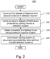
- a method of commissioning a lighting system comprising a plurality of lighting fixtures positioned at a plurality of physical locations, each lighting fixture having at least one signal generating device for generating a Radio Frequency, RF, output signal comprising a unique identifier identifying the lighting fixture.
- the method is performed by a processing device and comprises the steps of:
- Lighting fixtures arranged in a network of communicatively connected devices and provided with a signal generating device for generating an RF output signal, such as a wireless RF transceiver module, transmit RF signals that can be received by one or more detecting devices. It is observed that the RSSI level of an RF signal generated by a lighting fixture has a physically determined relationship with the physical distance between the lighting fixture generating the RF output signal and the detection location where the signal is detected. The present disclosure employs this observation to correlate respective lighting fixtures with their respective physical locations where a respective lighting fixture is installed or operates.
- a probability-based algorithm Processing, in a probability-based algorithm, the distances between a detection location and the physical locations of the lighting fixtures together with the RSSI levels produced by the RF output signals of the lighting fixtures, identified by their unique identifiers, and measured at the detection location, a probability is obtained of having a respective lighting fixture located at a respective physical location, or vice versa.
- Commissioning of the lighting system is performed by accumulating probabilities obtained for each pair of lighting fixture and physical location from the above processing with measurement data obtained at multiple detections locations. A physical location with the highest probability is identified as having the lighting fixture installed thereto.
- the detection locations are selected for receiving RF output signals produced by the lighting fixtures, such as in the vicinity of or overlap with the physical locations of the lighting fixtures. It is noted that, according to the present disclosure, the number of detection locations can be smaller than the number of physical locations of lighting fixtures. Thus, with the present disclosure, commissioning is performed without having to traverse all the physical locations, which results in a significant reduction in both work load for a system engineer conducting the commissioning of the lighting system and the overall time needed for the commissioning.
- a number of the detection locations is only a fraction of a number of the physical locations of the lighting fixtures.
- the number of the detection locations may be merely one-tenth (1/10), or even one-twentieth (1/20) of the number of the physical locations.
- the method is very efficient as commissioning is performed in less detection time and hence less costs when compared to the prior art commissioning methods as described in the background part above, for example.
- the detection locations are selected such that the physical locations of the lighting fixtures are substantially covered by the detection locations, which allows the commissioning to be performed with sufficient accuracy.
- the first dataset may be constructed from one of a floor plan designating the physical locations of the lighting fixtures and distance measurements.
- the first dataset may be generated, during the commissioning, by the processing device.
- the first dataset may be easily generated by the processing device during the commissioning process.
- the first dataset may be obtained from another source prior to the validation, such as from manual input or from architectural drawings, from dedicated distance measurement devices, or the like.
- the second dataset may be constructed by averaging RSSI levels received over a period of time.
- RSSI levels of the RF output signals received from each of the lighting fixtures may be collected over a period of time and averaged. This helps to obtain more accurate RSSI levels for use in the probability-based algorithm, which allows the relative arrangement of the respective lighting fixtures to be more precisely determined.
- the RSSI levels detected by the detecting device may be pre-processed or adapted, such as normalised, prior to the second dataset is constructed.
- the adaption improves the commissioning, as a possible influence from different RF transmit powers of the lighting fixtures may be eliminated by the adaption or pre-processing.
- applying the probability-based algorithm comprises the steps of:
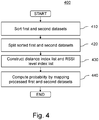
- both the first and second datasets are sorted before the probability of a lighting fixture being located at a physical location is computed, such that the sorted RSSI levels and sorted distances have comparable trends, which allows the mapping between the lighting fixtures and the physical locations to be obtained in an easier way.
- the sorted first dataset and the sorted second dataset may be further split into respective contiguous intervals, before the probability of a lighting fixture being located at a physical location is computed.
- the probability of a lighting fixture being located at a physical location is computed by mapping the split first dataset and the split second dataset for respective ones of the intervals. As each interval has a limited number of elements, the processing load is reduced after the splitting, which helps to improve the efficiency of the commissioning process.
- a distance index list may be constructed from the sorted and/or split first dataset and an RSSI level index list may be constructed the sorted and/or split second dataset, wherein each element of the distance index list corresponds to a physical location indicated by a distance between the physical location and the detection location, and each element of the RSSI level index list corresponds to a unique identifier of a lighting fixture.
- the construction of the distance and RSSI level index lists makes the mapping between the lighting fixtures and the physical locations easier as direct mapping between the distance index list and the RSSI level index list may be performed to compute the probability of a lighting fixture being located at a physical location.
- the step of computing the probability of a lighting fixture being located at a physical location comprises the steps of:
- the time and resource needed for computing the probability of a lighting fixture being located at a physical location is substantially reduced, as mapping is performed on a limited number of distances and RSSI levels. This again helps to improve the efficiency of the commissioning.
- the probability of a lighting fixture being located at a physical location may be computed using the following steps:
- the above steps perform the mapping starting from the lighting fixtures to the physical locations, which is an alternative way of computing the probability, and also has the advantage of reducing the processing load and making the commissioning faster.
- the probability-based algorithm may be applied to part of the first dataset having distances above a first threshold value and part of the second dataset having RSSI levels above a second threshold value.
- the RSSI levels may be obtained by one or more mobile detecting devices.
- the lighting fixtures are provided with detecting capability, for example having an RF sensor, the lighting fixtures may also function as the detecting device to detect the RSSI levels. In the latter case, commissioning according to the method of the present disclosure may be completely automatically performed.
- a second aspect of the present disclosure provides a device for commissioning a lighting system comprising a plurality of lighting fixtures positioned at a plurality of physical locations, each lighting fixture has at least one signal generating device for generating a Radio Frequency, RF, output signal comprising a unique identifier identifying the lighting fixture.
- the device comprises a processing device having a distance processing module, a Received Signal Strength Indicator, RSSI, level collecting module, a computing module and a location mapping module, which modules are operatively connected, wherein:
- the device may be further configured such that the RSSI level collecting module receives unique identifiers of the lighting fixtures and averages RSSI levels collected, for each of the lighting fixtures, over a period of time.
- the device may further comprise a report module for registering a result of commissioning in a storage device, for further use by the lighting system in performing advance lighting control.
- the device may be configured such that the distance processing module comprises an interface for inputting at least one of detection or detector locations and physical locations.
- a third aspect of the present disclosure provides a computer program product comprising program code means stored on a computer readable medium, the program code means arranged to perform the above commissioning method, when the program code is executed by at least one computer.
- the present disclosure is described in detail below with reference to a lighting system comprising lighting fixtures with Radio Frequency, RF, and/or optical sensors. Those skilled in the art will appreciate that the present disclosure is not limited to lighting fixtures with RF and optical sensors. Instead, lighting fixtures with other connectivity features may also be commissioned using the present disclosure.
- the method and device described herein rely on a signal generating capability of lighting devices, such as by an RF transceiver module of a networked lighting fixture, and a signal receiving capability of, for example, a mobile detecting device or RF sensors or receivers that are located within the lighting fixtures.
- the present disclosure further relies on the principle that strength of a signal detected at a spatial location is related to a distance between the spatial location and a source of the signal.
- the term 'distance' refers to direct spatial distance or distance of line of sight.
- an RSSI level generated by a lighting fixture has a substantially inverse relationship with a distance between the lighting fixture producing the RSSI level and a detection location where the RSSI level is detected, which makes it possible to determine relative spatial arrangement of the lighting fixtures.
- a signal received from the lighting fixture may include a unique identifier of the same, which makes it easily possible to discriminate between different lighting fixtures.
- the RSSI levels are used together with distances between individual physical locations and a number of detection locations to commission a lighting system, that is, to identify a mapping between a plurality of lighting fixtures and a plurality of physical locations having the lighting fixtures installed therein.
- FIG. 1 illustrates, schematically, a circuit diagram of an embodiment of one of a plurality of lighting fixtures 100 to be commissioned in accordance with the present disclosure.
- the lighting fixture 100 comprises a control part or control or node device 110 and a lighting device 120.
- the control device 110 comprises a transceiver, Tx/Rx, module 141 arranged for wireless 142 or wired 143 exchange of messages or data packets with a network gateway and/or other node devices.
- the transmission part of the transceiver may be used for generating RF signals which may be detected by other lighting fixtures or by a separate detecting device.
- the control device 110 further comprises at least one data processor or controller 145, and at least one data repository or storage or memory 146 for storing computer program code instructions.
- a unique identifier, ID, or unique address information 147 of the lighting fixture in a network may be stored in the repository 146, or a separate memory or storage accessible to the at least one processor or controller 145.
- the at least one processor or controller 145 communicatively interacts with and controls the transceiver 141 and the at least one repository or storage 146 via an internal data communication bus 148 of the control device 110.
- the unique address information may also be a physical identifier located on the lighting device 120.
- the control device 110 may be part of or operatively connect 144 to the lighting device 120, comprising a lighting module 121, preferably a LED lighting module, operation of which may be controlled by the control device 110 from or through a network gateway, or by a remote control device, for example.
- a lighting module 121 preferably a LED lighting module, operation of which may be controlled by the control device 110 from or through a network gateway, or by a remote control device, for example.
- the lighting fixture 100 may further comprise at least one sensor, for sensing an output signal of a lighting fixture 100, such as an RF sensor 131 and/or an optical sensor 132.
- An RF and/or light or another output signal generated by a lighting fixture 100 is received by the sensors 131 and/or 132 of other lighting fixtures or separate positioned sensors 131 and/or 132, such that distances between the lighting fixtures may be determined, which in turn will be used to determine a relative spatial arrangement of the lighting fixtures.
- the sensors 131, 132 or other signal receiving devices are arranged for obtaining signal strength of RF or light or other types of output signals generated by a lighting fixture.
- the lighting fixtures being enabled with connectivity features, allow for control and interaction among the lighting fixtures and/or with a mobile device or digital controller independent of the lighting fixtures. Specifically, RF signals from the lighting fixtures may be detected by a mobile device and/or by other similar lighting fixtures.
- each of the plurality of lighting fixtures to be commissioned produces an RF output signal, and RSSI levels of RF output signals produced by the lighting fixtures are obtained at a plurality of detection locations by at least one detecting device.
- the number of the detection locations is smaller than the number of the physical locations of the lighting fixtures.
- the method makes use of a probability-based algorithm to map the lighting fixtures to the physical locations.
- the method may compute a probability of the lighting fixture being located at a physical location of the plurality of physical locations, based on RSSI levels, corresponding to the lighting fixtures, obtained from each of the detection locations. The method may then identify a physical location with the highest probability having the lighting fixture located therein, for each lighting fixture, based on the probability of the lighting fixture being located at a respective physical location. Alternatively, the method may also identifies, for each of the physical locations, a lighting fixtures possibly located at the physical location using similar steps as described above.
- Figure 2 illustrates, in a flow chart, an example of detailed steps of a method 200 of commissioning a lighting system comprising a plurality of lighting fixtures 100, in accordance with the present disclosure.
- RF sensors 147 or transceivers 141 of the lighting fixtures may be used to obtain the RSSI signal strengths as well.
- Each lighting fixture is identified by a unique identifier 147, in this example its MAC address, indicated as MAC 1-25 .
- the mutual distance between the physical locations 310 of the lighting fixtures and between detection locations and the physical locations in one direction of the plane 300 is indicated by Dr and in another direction by Dc, respectively.
- the distances may be the same or different, for example a few meters, such as 2-5 meters, for example.
- a mobile detecting device 320 is placed at a number of detection locations at a distance beneath the plane 300 at which the lighting fixtures are installed.
- the mobile detecting device(s) 320 may be placed below a selected number of lighting fixtures, with the number of detection locations, which are selected for receiving RF output signals produced by said lighting fixtures, being smaller than the number of physical locations to be correlated to the lighting fixtures.
- the detection locations are selected such that the physical locations of the lighting fixtures are substantially covered by the detection locations, which allows sufficiently accurate commissioning information to be obtained. Less detection locations also mean significant reduction in both the legwork and processing load.
- the mobile detecting device(s) 320 may detect RSSI levels of RF signals output by the lighting fixtures.
- RSSI levels from each of the lighting fixtures may be collected over a period of time and averaged. This helps to obtain more accurate RSSI levels which allows the relative arrangement between the lighting fixtures to be more precisely determined.
- An exemplary floor plan as shown in Figure 3 contains twenty five physical locations arranged as a 5-by-5 grid, each physical location 310 has one lighting fixture installed thereto. Detection is conducted at nine detection locations as illustrated in Figure 3 by the position of the detection device(s). The selection of just nine detection locations is found, in this example, sufficient for ensuring accurate commissioning, as all the physical locations are essentially covered by the nine detection locations.
- the first dataset may be a distance vector.
- RSSI levels from all of the lighting fixtures are detected at the first detection location, and a second dataset is constructed from the detected RSSI levels.
- the second dataset is an RSSI level vector.
- a probability of a lighting fixture being located at a physical location is obtained by applying a probability-based algorithm to the first and second datasets.
- the above steps 210 to 230 are repeated for all nine detection locations, which gives probabilities of a lighting fixture being located at a physical location. That is, for each pair of lighting fixture and spatial location, nine probabilities are obtained, showing how likely that the lighting fixture may be located at the spatial locations.
- the commissioning of the lighting system is conducted by accumulating the probabilities obtained from all the detection locations. For each lighting fixture, a physical location with the highest probability is identified as having the lighting fixture located therein.
- Figure 4 illustrates, in a flow chart, an example of detailed steps of a method 400 of computing a probability of a lighting fixture being located at a physical location, in accordance with the present disclosure.
- both the first dataset, which is the distance vector, and the second dataset, which is the RSSI level vector are sorted.
- the distance vector may be obtained before or after the RSSI level vector, as long as both vectors, after being sorted, follow the same fashion or trend such that a proper correspondence between the two vectors is realised. That is, physical locations as indicated by indices corresponding to each element in the sorted distance vector and lighting fixtures as indicated by each RSSI level produced by a corresponding lighting fixture may be matched correctly, which allows probabilities of having a lighting fixture located at a group of physical locations to be calculated subsequently, or vice versa.
- the RSSI vector is sorted in a descending order, and the distance vector is sorted in an ascending order.
- the sorted RSSI level vector may be further split into multiple contiguous intervals.
- the multiple RSSI level intervals are decided according to RSSI level reference intervals which may be pre-selected based on experience.
- the sorted RSSI level vector is split into contiguous intervals as needed.
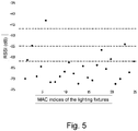
- Figure 5 illustrates along the vertical axis values of RSSI signals, measured in dB, obtained from all lighting fixtures, indicated by black dots and identified by their MAC address along the horizontal axis, detected at the first detection location of Figure 3 , i.e. with the detecting device 320 located at the left upper corner of Figure 3 .
- the RSSI levels as shown in Figure 5 are split, for example, into four contiguous intervals of: ⁇ [-47, max RSSI], [-55, -47), [-62, -55), [min RSSI, -62) ⁇ with max referring to maximum and min referring to minimum.
- An RSSI level index may be a unique identifier for identifying a lighting fixture which produces the corresponding RSSI level at the detection location, such as the MAC address of the lighting fixture.
- the RSSI level index list may be constructed from the sorted RSSI level vector, which will be used subsequently in mapping the sorted RSSI level vector and a sorted distance vector.
- the RSSI level intervals are considered when constructing the RSSI level index list.
- the following RSSI level index list is obtained: ⁇ [MAC 6 ], [MAC 3 , MAC 23 ], [MAC 2 , MAC 18 , MAC 20 ], [MAC 11 , MAC 25 , ...] ⁇
- the distance index list may be constructed from the sorted distance vector similarly.
- the sorted distance vector may be further split into intervals in the same fashion as that for the RSSI levels.
- the obtained distance index list is, for example, ⁇ [ d 1 ], [ d 2 , d 6 ], [ d 7 , d 3 , d 11 ], [ d 12 , d 8 , ...] ⁇ .
- This distance index list corresponds to a location sequence of lighting fixtures, for example, wherein identifies a lighting fixture i.
- both the distance vector and RSSI level vector are sorted in a way of allowing the distances and RSSI levels to have proper correspondence. That is, higher RSSI levels correspond to shorter distances, for example.
- a tolerance is considered and a subrange of distances is selected from the distance vector. From this distance subrange, an order range of the sorted distance vector is obtained.
- An RSSI level subrange corresponding to the selected distance subrange is selected, that is, RSSI levels falling into the same order range are selected. Then identifiers of lighting fixtures corresponding to the selected RSSI level range are identified. The method may then calculate probabilities of having the identified lighting fixtures installed at the physical location.
- identification is done from RSSI levels to distances, which identifies a group of physical location possibly having a lighting fixture installed thereto.
- Figure 6a is a graph illustrating another example of a sorted distance vector, ordered by increasing absolute distance in m, indicated along the vertical axis
- Figure 6b is a graph illustrating an example of a sorted RSSI vector, ordered by decreasing RSSI level in dB, indicated along the vertical axis. Both the sorted distance vector and the sorted RSSI level vector show a similar decreasing trend.
- Physical location 10 for example, has a distance of-28.6363 m from the detection location, indicated by the dotted line 600 in Figure 6a .
- a subrange 610 of [-28.0303, -26.2323] may be selected.
- this subrange 610 corresponds to an order range of [207, 216].
- FIG. 6b As indicated by reference numeral 620, lighting fixtures with RSSI levels falling into the order range [207, 216] are identified. The method may then compute the probability of having the identified lighting fixtures installed at physical location 10.
- step 440 for each of the lighting fixtures as in the RSSI level vector or RSSI level index list, probabilities of having the lighting fixture installed at a group of physical locations are calculated.
- the probabilities may be calculated by running through the RSSI level index list and the distance level index list.
- a probability of a lighting fixture identified by MAC 6 at location (No. 1 physical location) is 1.
- a lighting fixture identified by MAC 3 can possibly be located at location and , each with a probability of 1 ⁇ 2.
- Probabilities for lighting fixture MAC 23 are the same as for MAC 3 .
- For MAC 2 it can possibly be located at three locations and , each with a probability of 1/3.
- the lighting fixtures and the physical locations may be exchanged. That is, in another embodiment, the method may also determine a group of lighting fixtures each having a probability of being located at a physical location, and then determine the mapping between the lighting fixtures and the physical locations by accumulating the probabilities obtained at each detection location.
- the above method for commissioning a lighting system comprising multiple lighting fixtures uses less detection locations than the number of physical locations, for example half (1/2) the number of physical locations of lighting fixtures, or even one-tenth (1/10) or one-twentieth (1/20) of the number of the physical locations in case of hundreds of lighting fixtures. In this sense, the commissioning is performed without traversing all the physical locations, which results in a significant reduction in both work load for a system engineer conducting the commissioning of the lighting system and processing load needed for the commissioning.
- the above method may also be used to validate an existing commissioning information previously obtained via a different commissioning method, and thereby, improve the accuracy of the overall commissioning process, and/or for commissioning an upgraded system, i.e. extended by more lighting fixtures or wherein lighting fixtures are replaced by others, for example.
- an embodiment of the disclosure provides a device 700 for commissioning a lighting system comprising a plurality of lighting fixtures positioned at a plurality of physical locations, and each lighting fixture having at least one signal generating device for generating an RF output signal comprising a unique identifier identifying the lighting fixture.
- the device 700 comprises a processing device 710 having a distance processing module 720, an RSSI level collecting module 730, a computing module 740 and a location mapping module 750.
- the distance processing module 720 is arranged for constructing a first dataset comprising distances to the physical locations from a selected detection location or locations for measuring RSSI levels of signals produced by the lighting fixtures, such as in the vicinity of or at physical locations of the lighting fixtures.
- the RSSI level collecting module 730 is arranged for constructing a second dataset comprising RSSI levels of RF output signals produced by the lighting fixtures, identified by their unique identifiers ,and obtained by a detecting device at the detection location,
- the computing module 740 is arranged for obtaining a probability of a lighting fixture being located at a physical location by applying a probability-based algorithm to the first and second datasets.
- the location mapping module 750 is arranged for commissioning the lighting system by accumulating probabilities obtained from a plurality of detection locations, a number of the detection locations being smaller than a number of the physical locations.
- the RSSI level collecting module 730 may be further arranged for receiving unique identifiers of the lighting fixtures and for averaging RSSI levels collected, for each of the lighting fixtures, over a period of time.
- the processing device 710 may further comprises a report module 760 arranged for registering a result of commissioning in a storage device. Such result may then be used by a control system in performing advanced lighting control.
- the distance processing module 720 may comprise an interface 770 for inputting at least one of detection or detector locations and physical locations, either manually or electronically obtained from a floor plan, architectural drawings, or a distance measurement device, and the like.
- another embodiment of the present disclosure provides a computer program product comprising program code means stored on a computer readable medium, the program code means arranged to perform the above commissioning method, when the program code is executed by at least one computer.
- the above devices may be implemented based on discrete hardware circuitries with discrete hardware components, integrated chips, or arrangements of chip modules, or based on signal processing devices or chips controlled by software routines or programs stored in memories, written on a computer readable media, or downloaded from a network, such as the Internet.
- the devices, the commissioning and/or control device, a luminaire device, a lighting system, the method, and the computer program product of the above aspects may have similar and/or identical preferred embodiments, in particular, as defined in the dependent claims.
Landscapes
- Engineering & Computer Science (AREA)
- Computer Networks & Wireless Communication (AREA)
- Circuit Arrangement For Electric Light Sources In General (AREA)
Applications Claiming Priority (2)
| Application Number | Priority Date | Filing Date | Title |
|---|---|---|---|
| CN2018122851 | 2018-12-21 | ||
| EP19158832 | 2019-02-22 |
Publications (2)
| Publication Number | Publication Date |
|---|---|
| EP3672335A1 true EP3672335A1 (de) | 2020-06-24 |
| EP3672335B1 EP3672335B1 (de) | 2023-11-08 |
Family
ID=68766691
Family Applications (1)
| Application Number | Title | Priority Date | Filing Date |
|---|---|---|---|
| EP19214798.1A Active EP3672335B1 (de) | 2018-12-21 | 2019-12-10 | Verfahren und vorrichtung zur inbetriebnahme eines beleuchtungssystems |
Country Status (2)
| Country | Link |
|---|---|
| US (1) | US11044797B2 (de) |
| EP (1) | EP3672335B1 (de) |
Citations (4)
| Publication number | Priority date | Publication date | Assignee | Title |
|---|---|---|---|---|
| WO2008129488A2 (en) * | 2007-04-24 | 2008-10-30 | Koninklijke Philips Electronics N. V. | System and method for recalculation of probabilities in decision trees |
| US8825078B1 (en) | 2011-08-18 | 2014-09-02 | Google Inc. | Probabilistic estimation of location based on wireless signal strength |
| WO2018024528A1 (en) * | 2016-08-05 | 2018-02-08 | Philips Lighting Holding B.V. | Building automation system with commissioning device |
| US20180270933A1 (en) * | 2015-09-18 | 2018-09-20 | Philips Lighting Holding B.V. | Systems and methods for automatic lighting fixture location mapping |
Family Cites Families (6)
| Publication number | Priority date | Publication date | Assignee | Title |
|---|---|---|---|---|
| JP5818779B2 (ja) | 2009-03-23 | 2015-11-18 | コーニンクレッカ フィリップス エヌ ヴェKoninklijke Philips N.V. | フィンガープリント法を用いた位置検出システム及び位置検出方法 |
| US9208680B2 (en) | 2012-01-12 | 2015-12-08 | Lumen Radio Ab | Remote commissioning of an array of networked devices |
| US9121931B2 (en) | 2013-03-15 | 2015-09-01 | Blackberry Limited | Mobile device location estimation |
| CA2931526C (en) * | 2013-11-25 | 2022-04-19 | Abl Ip Holding Llc | System and method for communication with a mobile device via a positioning system including rf communication devices and modulated beacon light sources |
| US10789843B2 (en) * | 2017-05-16 | 2020-09-29 | Universal Lighting Technologies, Inc. | Method for automatically locating and commissioning lighting system components |
| US11051386B2 (en) * | 2018-09-06 | 2021-06-29 | Lsi Industries, Inc. | Distributed intelligent network-based lighting system |
-
2019
- 2019-12-10 EP EP19214798.1A patent/EP3672335B1/de active Active
- 2019-12-10 US US16/708,811 patent/US11044797B2/en active Active
Patent Citations (4)
| Publication number | Priority date | Publication date | Assignee | Title |
|---|---|---|---|---|
| WO2008129488A2 (en) * | 2007-04-24 | 2008-10-30 | Koninklijke Philips Electronics N. V. | System and method for recalculation of probabilities in decision trees |
| US8825078B1 (en) | 2011-08-18 | 2014-09-02 | Google Inc. | Probabilistic estimation of location based on wireless signal strength |
| US20180270933A1 (en) * | 2015-09-18 | 2018-09-20 | Philips Lighting Holding B.V. | Systems and methods for automatic lighting fixture location mapping |
| WO2018024528A1 (en) * | 2016-08-05 | 2018-02-08 | Philips Lighting Holding B.V. | Building automation system with commissioning device |
Also Published As
| Publication number | Publication date |
|---|---|
| EP3672335B1 (de) | 2023-11-08 |
| US20200205272A1 (en) | 2020-06-25 |
| US11044797B2 (en) | 2021-06-22 |
Similar Documents
| Publication | Publication Date | Title |
|---|---|---|
| EP3351055B1 (de) | Systeme und verfahren zur automatischen leuchtenstandortkartierung | |
| US9996057B2 (en) | Methods for automatically commissioning of devices of a networked control system | |
| US20090066473A1 (en) | Commissioning wireless network devices according to an installation plan | |
| US9693428B2 (en) | Lighting control with automated activation process | |
| EP1862036B1 (de) | Gruppierung drahtloser beleuchtungsknoten nach gebäuderaumanordnung | |
| CN109791191B (zh) | 信标验证设备 | |
| CN101138281A (zh) | 用于无线照明分配的墙检测 | |
| EP3342257A1 (de) | Systeme und verfahren zur leuchtenstandortkartierung | |
| KR20110082044A (ko) | 장치의 자동 할당을 위한 방법 및 장치 | |
| EP3672335B1 (de) | Verfahren und vorrichtung zur inbetriebnahme eines beleuchtungssystems | |
| US10524138B2 (en) | System for RF quiet channel optimization | |
| US10789843B2 (en) | Method for automatically locating and commissioning lighting system components | |
| US11729592B2 (en) | Angle of arrival commissioning of lighting devices | |
| CN105182761A (zh) | 指定操作触发方法及装置 | |
| JP7245836B2 (ja) | 位置検出システム、算出装置、プログラムおよび位置検出方法 | |
| JP7167157B2 (ja) | 位置検出システム、算出装置、プログラムおよび位置検出方法 | |
| JP7245837B2 (ja) | 位置検出システム、算出装置、プログラムおよび位置検出方法 | |
| CN108254720B (zh) | 一种物品位置信息检测设备和方法 | |
| CN112673713B (zh) | 用于调试光源的方法、系统、装置和计算机可读介质 | |
| CN111614789B (zh) | 一种检测室分天线地址的方法及检测设备 | |
| KR20110074113A (ko) | 무선신호 간섭 모니터링 방법 및 그에 따른 시스템 |
Legal Events
| Date | Code | Title | Description |
|---|---|---|---|
| PUAI | Public reference made under article 153(3) epc to a published international application that has entered the european phase |
Free format text: ORIGINAL CODE: 0009012 |
|
| STAA | Information on the status of an ep patent application or granted ep patent |
Free format text: STATUS: THE APPLICATION HAS BEEN PUBLISHED |
|
| AK | Designated contracting states |
Kind code of ref document: A1 Designated state(s): AL AT BE BG CH CY CZ DE DK EE ES FI FR GB GR HR HU IE IS IT LI LT LU LV MC MK MT NL NO PL PT RO RS SE SI SK SM TR |
|
| AX | Request for extension of the european patent |
Extension state: BA ME |
|
| STAA | Information on the status of an ep patent application or granted ep patent |
Free format text: STATUS: REQUEST FOR EXAMINATION WAS MADE |
|
| 17P | Request for examination filed |
Effective date: 20210111 |
|
| RBV | Designated contracting states (corrected) |
Designated state(s): AL AT BE BG CH CY CZ DE DK EE ES FI FR GB GR HR HU IE IS IT LI LT LU LV MC MK MT NL NO PL PT RO RS SE SI SK SM TR |
|
| STAA | Information on the status of an ep patent application or granted ep patent |
Free format text: STATUS: EXAMINATION IS IN PROGRESS |
|
| 17Q | First examination report despatched |
Effective date: 20211201 |
|
| GRAP | Despatch of communication of intention to grant a patent |
Free format text: ORIGINAL CODE: EPIDOSNIGR1 |
|
| STAA | Information on the status of an ep patent application or granted ep patent |
Free format text: STATUS: GRANT OF PATENT IS INTENDED |
|
| INTG | Intention to grant announced |
Effective date: 20230605 |
|
| GRAS | Grant fee paid |
Free format text: ORIGINAL CODE: EPIDOSNIGR3 |
|
| GRAA | (expected) grant |
Free format text: ORIGINAL CODE: 0009210 |
|
| STAA | Information on the status of an ep patent application or granted ep patent |
Free format text: STATUS: THE PATENT HAS BEEN GRANTED |
|
| AK | Designated contracting states |
Kind code of ref document: B1 Designated state(s): AL AT BE BG CH CY CZ DE DK EE ES FI FR GB GR HR HU IE IS IT LI LT LU LV MC MK MT NL NO PL PT RO RS SE SI SK SM TR |
|
| P01 | Opt-out of the competence of the unified patent court (upc) registered |
Effective date: 20230929 |
|
| REG | Reference to a national code |
Ref country code: GB Ref legal event code: FG4D |
|
| REG | Reference to a national code |
Ref country code: CH Ref legal event code: EP |
|
| REG | Reference to a national code |
Ref country code: DE Ref legal event code: R096 Ref document number: 602019040974 Country of ref document: DE |
|
| REG | Reference to a national code |
Ref country code: IE Ref legal event code: FG4D |
|
| PGFP | Annual fee paid to national office [announced via postgrant information from national office to epo] |
Ref country code: GB Payment date: 20231219 Year of fee payment: 5 |
|
| PGFP | Annual fee paid to national office [announced via postgrant information from national office to epo] |
Ref country code: FR Payment date: 20231226 Year of fee payment: 5 |
|
| REG | Reference to a national code |
Ref country code: LT Ref legal event code: MG9D |
|
| REG | Reference to a national code |
Ref country code: NL Ref legal event code: MP Effective date: 20231108 |
|
| PG25 | Lapsed in a contracting state [announced via postgrant information from national office to epo] |
Ref country code: GR Free format text: LAPSE BECAUSE OF FAILURE TO SUBMIT A TRANSLATION OF THE DESCRIPTION OR TO PAY THE FEE WITHIN THE PRESCRIBED TIME-LIMIT Effective date: 20240209 |
|
| PG25 | Lapsed in a contracting state [announced via postgrant information from national office to epo] |
Ref country code: IS Free format text: LAPSE BECAUSE OF FAILURE TO SUBMIT A TRANSLATION OF THE DESCRIPTION OR TO PAY THE FEE WITHIN THE PRESCRIBED TIME-LIMIT Effective date: 20240308 |
|
| PG25 | Lapsed in a contracting state [announced via postgrant information from national office to epo] |
Ref country code: LT Free format text: LAPSE BECAUSE OF FAILURE TO SUBMIT A TRANSLATION OF THE DESCRIPTION OR TO PAY THE FEE WITHIN THE PRESCRIBED TIME-LIMIT Effective date: 20231108 |
|
| REG | Reference to a national code |
Ref country code: AT Ref legal event code: MK05 Ref document number: 1630779 Country of ref document: AT Kind code of ref document: T Effective date: 20231108 |
|
| PG25 | Lapsed in a contracting state [announced via postgrant information from national office to epo] |
Ref country code: NL Free format text: LAPSE BECAUSE OF FAILURE TO SUBMIT A TRANSLATION OF THE DESCRIPTION OR TO PAY THE FEE WITHIN THE PRESCRIBED TIME-LIMIT Effective date: 20231108 |
|
| PG25 | Lapsed in a contracting state [announced via postgrant information from national office to epo] |
Ref country code: AT Free format text: LAPSE BECAUSE OF FAILURE TO SUBMIT A TRANSLATION OF THE DESCRIPTION OR TO PAY THE FEE WITHIN THE PRESCRIBED TIME-LIMIT Effective date: 20231108 |
|
| PG25 | Lapsed in a contracting state [announced via postgrant information from national office to epo] |
Ref country code: ES Free format text: LAPSE BECAUSE OF FAILURE TO SUBMIT A TRANSLATION OF THE DESCRIPTION OR TO PAY THE FEE WITHIN THE PRESCRIBED TIME-LIMIT Effective date: 20231108 |
|
| PG25 | Lapsed in a contracting state [announced via postgrant information from national office to epo] |
Ref country code: NL Free format text: LAPSE BECAUSE OF FAILURE TO SUBMIT A TRANSLATION OF THE DESCRIPTION OR TO PAY THE FEE WITHIN THE PRESCRIBED TIME-LIMIT Effective date: 20231108 Ref country code: LT Free format text: LAPSE BECAUSE OF FAILURE TO SUBMIT A TRANSLATION OF THE DESCRIPTION OR TO PAY THE FEE WITHIN THE PRESCRIBED TIME-LIMIT Effective date: 20231108 Ref country code: IS Free format text: LAPSE BECAUSE OF FAILURE TO SUBMIT A TRANSLATION OF THE DESCRIPTION OR TO PAY THE FEE WITHIN THE PRESCRIBED TIME-LIMIT Effective date: 20240308 Ref country code: GR Free format text: LAPSE BECAUSE OF FAILURE TO SUBMIT A TRANSLATION OF THE DESCRIPTION OR TO PAY THE FEE WITHIN THE PRESCRIBED TIME-LIMIT Effective date: 20240209 Ref country code: ES Free format text: LAPSE BECAUSE OF FAILURE TO SUBMIT A TRANSLATION OF THE DESCRIPTION OR TO PAY THE FEE WITHIN THE PRESCRIBED TIME-LIMIT Effective date: 20231108 Ref country code: BG Free format text: LAPSE BECAUSE OF FAILURE TO SUBMIT A TRANSLATION OF THE DESCRIPTION OR TO PAY THE FEE WITHIN THE PRESCRIBED TIME-LIMIT Effective date: 20240208 Ref country code: AT Free format text: LAPSE BECAUSE OF FAILURE TO SUBMIT A TRANSLATION OF THE DESCRIPTION OR TO PAY THE FEE WITHIN THE PRESCRIBED TIME-LIMIT Effective date: 20231108 Ref country code: PT Free format text: LAPSE BECAUSE OF FAILURE TO SUBMIT A TRANSLATION OF THE DESCRIPTION OR TO PAY THE FEE WITHIN THE PRESCRIBED TIME-LIMIT Effective date: 20240308 |
|
| PGFP | Annual fee paid to national office [announced via postgrant information from national office to epo] |
Ref country code: DE Payment date: 20240228 Year of fee payment: 5 |