EP3672318B1 - Procédé et appareil de transmission de paquet dans un système de communication sans fil - Google Patents
Procédé et appareil de transmission de paquet dans un système de communication sans fil Download PDFInfo
- Publication number
- EP3672318B1 EP3672318B1 EP18860250.2A EP18860250A EP3672318B1 EP 3672318 B1 EP3672318 B1 EP 3672318B1 EP 18860250 A EP18860250 A EP 18860250A EP 3672318 B1 EP3672318 B1 EP 3672318B1
- Authority
- EP
- European Patent Office
- Prior art keywords
- packet
- duplication
- rlc
- information
- layer
- Prior art date
- Legal status (The legal status is an assumption and is not a legal conclusion. Google has not performed a legal analysis and makes no representation as to the accuracy of the status listed.)
- Active
Links
- 238000004891 communication Methods 0.000 title claims description 113
- 238000000034 method Methods 0.000 title claims description 74
- 230000002776 aggregation Effects 0.000 claims description 8
- 238000004220 aggregation Methods 0.000 claims description 8
- 230000005540 biological transmission Effects 0.000 description 26
- 239000000969 carrier Substances 0.000 description 22
- 230000008569 process Effects 0.000 description 22
- 238000012545 processing Methods 0.000 description 17
- 230000006870 function Effects 0.000 description 13
- 230000015654 memory Effects 0.000 description 10
- 238000005516 engineering process Methods 0.000 description 7
- 238000013507 mapping Methods 0.000 description 5
- 230000000694 effects Effects 0.000 description 4
- 238000010397 one-hybrid screening Methods 0.000 description 4
- 230000001174 ascending effect Effects 0.000 description 2
- 230000007774 longterm Effects 0.000 description 2
- 230000009466 transformation Effects 0.000 description 2
- 238000012935 Averaging Methods 0.000 description 1
- DWDGSKGGUZPXMQ-UHFFFAOYSA-N OPPO Chemical compound OPPO DWDGSKGGUZPXMQ-UHFFFAOYSA-N 0.000 description 1
- 230000001413 cellular effect Effects 0.000 description 1
- 238000001514 detection method Methods 0.000 description 1
- 238000011161 development Methods 0.000 description 1
- 238000010586 diagram Methods 0.000 description 1
- 230000006872 improvement Effects 0.000 description 1
- 230000003287 optical effect Effects 0.000 description 1
- 230000001151 other effect Effects 0.000 description 1
- 230000011664 signaling Effects 0.000 description 1
Images


Classifications
-
- H—ELECTRICITY
- H04—ELECTRIC COMMUNICATION TECHNIQUE
- H04L—TRANSMISSION OF DIGITAL INFORMATION, e.g. TELEGRAPHIC COMMUNICATION
- H04L1/00—Arrangements for detecting or preventing errors in the information received
- H04L1/08—Arrangements for detecting or preventing errors in the information received by repeating transmission, e.g. Verdan system
-
- H—ELECTRICITY
- H04—ELECTRIC COMMUNICATION TECHNIQUE
- H04L—TRANSMISSION OF DIGITAL INFORMATION, e.g. TELEGRAPHIC COMMUNICATION
- H04L1/00—Arrangements for detecting or preventing errors in the information received
- H04L1/0001—Systems modifying transmission characteristics according to link quality, e.g. power backoff
- H04L1/0015—Systems modifying transmission characteristics according to link quality, e.g. power backoff characterised by the adaptation strategy
- H04L1/0017—Systems modifying transmission characteristics according to link quality, e.g. power backoff characterised by the adaptation strategy where the mode-switching is based on Quality of Service requirement
-
- H—ELECTRICITY
- H04—ELECTRIC COMMUNICATION TECHNIQUE
- H04W—WIRELESS COMMUNICATION NETWORKS
- H04W28/00—Network traffic management; Network resource management
- H04W28/02—Traffic management, e.g. flow control or congestion control
- H04W28/0252—Traffic management, e.g. flow control or congestion control per individual bearer or channel
- H04W28/0263—Traffic management, e.g. flow control or congestion control per individual bearer or channel involving mapping traffic to individual bearers or channels, e.g. traffic flow template [TFT]
-
- H—ELECTRICITY
- H04—ELECTRIC COMMUNICATION TECHNIQUE
- H04W—WIRELESS COMMUNICATION NETWORKS
- H04W28/00—Network traffic management; Network resource management
- H04W28/02—Traffic management, e.g. flow control or congestion control
- H04W28/0268—Traffic management, e.g. flow control or congestion control using specific QoS parameters for wireless networks, e.g. QoS class identifier [QCI] or guaranteed bit rate [GBR]
-
- H—ELECTRICITY
- H04—ELECTRIC COMMUNICATION TECHNIQUE
- H04W—WIRELESS COMMUNICATION NETWORKS
- H04W28/00—Network traffic management; Network resource management
- H04W28/02—Traffic management, e.g. flow control or congestion control
- H04W28/04—Error control
-
- H—ELECTRICITY
- H04—ELECTRIC COMMUNICATION TECHNIQUE
- H04W—WIRELESS COMMUNICATION NETWORKS
- H04W28/00—Network traffic management; Network resource management
- H04W28/02—Traffic management, e.g. flow control or congestion control
Definitions
- the disclosure generally relates to a wireless communication system and, more particularly, to an apparatus and a method for transmitting a packet in a wireless communication system.
- the 5G or pre-5G communication system is also called a ⁇ Beyond 4G Network' or a 'Post Long Term Evolution (LTE) System'.
- the 5G communication system is considered to be implemented in higher frequency (mmWave) bands, e.g., 60GHz bands, so as to accomplish higher data rates.
- mmWave e.g., 60GHz bands
- MIMO massive multiple-input multiple-output
- FD-MIMO Full Dimensional MIMO
- array antenna an analog beam forming, large scale antenna techniques are discussed in 5G communication systems.
- RANs Cloud Radio Access Networks
- D2D device-to-device
- wireless backhaul moving network
- cooperative communication Coordinated Multi-Points (CoMP), reception-end interference cancellation and the like.
- CoMP Coordinated Multi-Points
- FSK Hybrid frequency shift keying
- FQAM quadrature amplitude modulation
- SWSC sliding window superposition coding
- ACM advanced coding modulation
- FBMC filter bank multi carrier
- NOMA non-orthogonal multiple access
- SCMA sparse code multiple access
- packet duplication technology As one method to improve the reliability of transmission of data.
- a transmitter may produce a plurality of packets by duplicating one packet, and may transmit the packets through different paths. This is intended to prepare for the situation in which data is lost. Therefore, detailed procedures for introducing packet duplication technology to 5G systems are under discussion.
- SHARP "PDCP Duplication in CA”
- 3GPP DRAFT R2-1706791 2017-06-26
- VIVO "PDCP duplication impacts on LCP”
- 3GPP DRAFT R2-1708502 2017-08-20
- ITL “Configuration of PDCP duplication”
- 3GPP DRAFT R2-1709628 2017-08-20
- INTERDIGITAL COMMUNICATIONS "Packet Duplication at PDCP
- 3GPP DRAFT R2-1701186 2017-02-12
- OPPO "Packet duplication in CAbased eV2x”
- 3GPP DRAFT R2-1707699 2017-08-20
- the disclosure provides an apparatus and a method for efficiently transmitting a packet in a wireless communication system.
- an operation method of a transmitter is disclosed in claim 1.
- an operation method of a receiver is disclosed in claim 6.
- An apparatus and a method according to various embodiments of the disclosure enable efficient transmission and reception of data packets in a wireless communication system.
- the disclosure relates to an apparatus and a method for transmitting packets in a wireless communication system. Specifically, the disclosure describes a technique for transmitting packets using packet duplication technology in a wireless communication system.
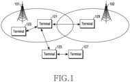
- FIG. 1 illustrates a wireless communication system according to various embodiments of the disclosure.
- FIG. 1 illustrates base stations 101 and 102 and terminals 121, 123, 125, 127, and 129 as parts of nodes using wireless channels in a wireless communication system.
- the base stations 101 and 102 are network infrastructure that provides wireless access to the terminals 121, 123, 125, 127, and 129.
- the base station 101 or 102 has a coverage defined as a certain geographic area based on the distance over which signals can be transmitted.
- the base station 101 or 102 may be referred to as an "access point (AP)", an “eNodeB (eNB)", a “5th generation (5G) node”, a “wireless point”, a “transmission/reception point (TRP)”, or other terms having equivalent technical meanings, as well as "base station”.
- Each of the terminals 121, 123, 125, 127, and 129 is a device used by a user and communicates with the base stations 101 and 102 via wireless channels. In some cases, at least one of the terminals 121, 123, 125, 127, and 129 may be operated without user involvement. That is, at least one of the terminals 121, 123, 125, 127, and 129 may be a device for performing machine-type communication (MTC), and may not be carried by a user.
- MTC machine-type communication
- Each of the terminals 121, 123, 125, 127, and 129 may be referred to as "user equipment (UE)", a “mobile station”, a “subscriber station”, a “remote terminal”, a “wireless terminal”, a “user device”, or other terms having equivalent technical meanings, as well as “terminal”.
- UE user equipment
- communication may be made between the base station 101 and the terminal 121.
- communication using a direct link between any two terminals may be performed. That is, communication using a direct link may be made between two terminals 121 and 123 within the service range of the base station 101, communication using a direct link may be made between a terminal 121 within the service range of the base station 101 and a terminal 125 outside the service range thereof, and communication using a direct link may be made between two terminals 125 and 127 outside the service range of the base station 101.
- communication using a direct link may be performed between the terminals 121 and 129 which fall wihtin service ranges of different base stations 101 and 102, respectively.
- the terminals 121, 123, 125, 127, and 129 may use an intelligent transportation systems (ITS) band (e.g., 5.9 GHz), instead of using the frequency resources of the base stations 101 and 102.
- ITS intelligent transportation systems
- the terminals 121 and 123 within the service range of the base station 101 may configure parameters for communication by the base station 101
- the terminal 129 within the service range of the base station 102 may configure parameters for communication by the base station 102
- the terminals 125 and 127 located outside the service range of the base station 101 may operate according to a predefined configuration.
- the terminals 121, 123, 125, and 127 may operate as a transmitter or a receiver in performing communication with each other.
- the roles of the transmitter and the receiver are not fixed, but may be variable.
- the terminal 121 may operate as a transmitter in a certain time, and may operate as a receiver in another time.
- the terminal 121 may operate as a transmitter in one frequency band, and may operate as a receiver in another frequency band.
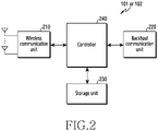
- FIG. 2 illustrates the configuration of a base station in a wireless communication system according to various embodiments of the disclosure.
- the configuration illustrated in FIG. 2 may be regarded as the configuration of the base station 101.
- the term "-unit”, “-or (er)”, or the like denotes a unit for processing at least one function or operation, and may be implemented as hardware, software, or a combination thereof.
- the base station includes a wireless communication unit 210, a backhaul communication unit 220, a storage unit 230, and a controller 240.
- the wireless communication unit 210 may perform functions of transmitting and receiving signals via a wireless channel.
- the wireless communication unit 210 may perform a function of transformation between a baseband signal and a bit stream according to the physical layer standard of a system.
- the wireless communication unit 210 may produce complex symbols by encoding and modulating a transmission bit stream.
- the wireless communication unit 210 may restore a reception bit stream by demodulating and decoding a baseband signal.
- the wireless communication unit 210 may up-convert a baseband signal to a radio frequency (RF) band signal to thus transmit the same via an antenna, and may down-convert an RF band signal received via the antenna to a baseband signal.
- the wireless communication unit 210 may include a transmitting filter, a receiving filter, an amplifier, a mixer, an oscillator, a digital-toanalog convertor (DAC), an analog-to-digital convertor (ADC), and the like.
- the wireless communication unit 210 may include a plurality of transmission/reception paths. Further, the wireless communication unit 210 may include at least one antenna array including a plurality of antenna elements.
- the wireless communication unit 210 may include a digital unit and an analog unit, and the analog unit may include a plurality of subunits depending on the operation power, operation frequency, or the like.
- the digital unit may include at least processor ⁇ e.g., a digital signal processor (DSP) ⁇ .
- DSP digital signal processor
- the wireless communication unit 210 may transmit and receive signals as described above. Accordingly, all or some of the wireless communication unit 210 may be referred to as a "transmitter”, a “receiver”, or a “transceiver”. In the following description, the transmission and reception performed via a wireless channel will have a meaning encompassing the execution of the process by the wireless communication unit 210 as described above.
- the backhaul communication unit 220 provides an interface for communication with other nodes in the network. That is, the backhaul communication unit 220 converts a bit stream, transmitted from the base station to another node, such as another access node, another base station, an upper node, or a core network, into a physical signal, and converts a physical signal received from another node into a bit stream.
- another node such as another access node, another base station, an upper node, or a core network
- the storage unit 230 stores data such as fundamental programs, application programs, and configuration information for the operation of the base station.
- the storage unit 230 may be configured as volatile memory, nonvolatile memory, or a combination thereof.
- the storage unit 230 provides the stored data upon request by the controller 240.
- the controller 240 controls the overall operation of the base station. For example, the controller 240 transmits and receives signals via the wireless communication unit 210 or the backhaul communication unit 220. The controller 240 writes or reads data to or from the storage unit 230. In addition, the controller 240 may perform the functions of a protocol stack required for the communication standard. Alternatively, the protocol stack may be included in the wireless communication unit 210. To this end, the controller 240 may include at least one processor.
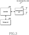
- FIG. 3 illustrates the configuration of a terminal in a wireless communication system according to various embodiments of the disclosure.
- the configuration illustrated in FIG. 3 may be regarded as the configuration of one of the terminals 121, 123, 125, 127, and 129.
- the term "-unit”, “-or (er)”, or the like denotes a unit for processing at least one function or operation, and may be implemented by hardware, software, or a combination thereof.
- the terminal includes a communication unit 310, a storage unit 320, and a controller 330.
- the communication unit 310 performs functions of transmitting and receiving signals via a wireless channel.
- the communication unit 310 may perform a function of transformation between a baseband signal and a bit stream according to the physical layer standard of a system.
- the communication unit 310 may produce complex symbols by encoding and modulating a transmission bit stream.
- the communication unit 310 may restore a reception bit stream by demodulating and decoding a baseband signal.
- the communication unit 310 may up-convert a baseband signal to an RF band signal to thus transmit the same via an antenna, and may down-convert an RF band signal received via the antenna to a baseband signal.
- the communication unit 310 may include a transmitting filter, a receiving filter, an amplifier, a mixer, an oscillator, a DAC, an ADC, and the like.
- the communication unit 310 may include a plurality of transmission/reception paths. Further, the communication unit 310 may include at least one antenna array including a plurality of antenna elements. In terms of hardware, the communication unit 310 may include a digital circuit and an analog circuit ⁇ e.g., a radio frequency integrated circuit (RFIC) ⁇ . The digital circuit and the analog circuit may be implemented as a single package. In addition, the communication unit 310 may include a plurality of RF chains. The communication unit 310 may perform beamforming.
- RFIC radio frequency integrated circuit
- the communication unit 310 may include a plurality of communication modules to support a plurality of different wireless access technologies.
- the different wireless access technologies may include Bluetooth Low Energy (BLE), Wireless Fidelity (Wi-Fi), Wi-Fi Gigabyte (WiGig), cellular networks ⁇ e.g., Long-Term Evolution (LTE) ⁇ , and the like.
- different frequency bands may include a super-high frequency (SHF) (e.g., 3.5GHz or 5GHz) band and a millimeter wave (e.g., 60GHz) band.
- SHF super-high frequency
- 60GHz millimeter wave
- the communication unit 310 transmits and receives signals as described above. Accordingly, all or some of the communication unit 310 may be referred to as a "transmitter”, a “receiver”, or a “transceiver”. In the following description, transmission and reception performed via a wireless channel will have a meaning encompassing execution of the process by the communication unit 310 as described above.
- the storage unit 320 may store data such as fundamental programs for the operation of the terminal, application programs, and data such as configuration information.
- the storage unit 320 may be configured as volatile memory, nonvolatile memory, or a combination thereof.
- the storage unit 320 provides the stored data upon request by the controller 330.
- the controller 330 controls the overall operation of the terminal. For example, the controller 330 transmits and receives signals via the communication unit 310. The controller 330 writes or reads data to or from the storage unit 320. The controller 330 may perform the functions of a protocol stack required for the communication standard. To this end, the controller 330 may include at least one processor or microprocessor, or may be a part of a processor. In addition, a part of the communication unit 310 and the controller 330 may be referred to as a "communication processor (CP)".
- CP communication processor
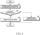
- FIG. 4 is a flowchart illustrating the operation of a transmitter according to the first embodiment of the claimed invention.
- FIG. 4 illustrates an operation method of a terminal (e.g., the terminal 121, the terminal 123, the terminal 125, or the terminal 127) operating as a transmitter.
- a terminal e.g., the terminal 121, the terminal 123, the terminal 125, or the terminal 1257 operating as a transmitter.
- the transmitter determines a parameter according to QoS information or a service type.
- the QoS information may include at least one of a QoS class identifier (QCI), a packet delay budget, and a packet error loss rate.
- QCI QoS class identifier
- the QoS information is, according to the invention, defined according to a service type in an application layer. In other examples, the QoS information may be defined according to information on a packet in a higher layer, for example, in an application layer, such as at least one of a source address, a destination address, or a port number of a packet.
- the parameter may be defined in various ways.
- the parameter may include at least one piece of first information on priority for packet transmission and second information on reliability.
- the first information may be determined based on the delay of packet transmission. The lower the delay of the packet transmission, the higher the priority of the packet transmission. Thus, the first information may be determined to be higher.
- the second information may be determined based on a required error rate, and may indicate a level of reliability required for each radio bearer or packet. The lower the required error rate of the packet, the higher the level of reliability. Thus, the second information may be determined to be higher.
- the first information may be referred to as "ProSe priority per packet (PPPP)"
- the second information may be referred to as "ProSe reliability per packet (PRPP)".
- the transmitter determines whether or not to duplicate a packet. In other words, the transmitter determines whether or not to duplicate a packet, based on the parameter determined in step 401.
- the second information of the parameter indicates information related to whether or not to duplicate a packet, and may be expressed as a value indicating a positive/negative value (e.g., a flag of 1 bit) or a constant value. For example, in the case where the second information is a flag, it may be expressed as 0 or 1 to indicate whether or not to perform packet duplication. Alternatively, if the second information is a constant value, the second information may reflect a packet error loss rate of the QoS. In this case, if the second information is greater than or equal to a specific threshold, the transmitter may determine to perform packet duplication.
- step 405 if the transmitter determines to perform packet duplication, the transmitter duplicates one packet and transmits two or more duplicated packets to a receiver.
- Two or more duplicated packets are, according to the invention, transmitted through two or more component carriers that perform carrier aggregation (CA). That is, the respective duplicated packets are, according to the invention, transmitted to the receiver through different component carriers.
- CA carrier aggregation
- the transmitter transmits one packet to the receiver as normal packet transmission in step 407. In other words, the transmitter transmits one original packet to the receiver without packet duplication.
- the transmitter may activate or deactivate duplication of a packet for a sidelink, based on pre-configuration or configuration through messages.
- Second information for supporting sidelink packet duplication that is, a PRPP threshold value, may be preconfigured or configured through a message.
- FIG. 5 is a flowchart illustrating the operation of a receiver according to the second embodiment of the claimed invention.
- FIG. 5 illustrates an operation method of a terminal (e.g., the terminal 121, the terminal 123, the terminal 125, or the terminal 127) operating as a receiver.
- a terminal e.g., the terminal 121, the terminal 123, the terminal 125, or the terminal 1257 operating as a receiver.
- the receiver obtains packet duplication configuration information.
- the packet duplication configuration information includes at least one parameter for determining whether or not packet duplication is applied.
- the packet duplication configuration information may be QoS-related information of a service, or may include control information received from a transmitter.
- the receiver determines whether or not packet duplication is performed. That is, the receiver determines whether or not the transmitter transmits a packet using packet duplication. For example, if the packet duplication configuration information includes QoS-related information of a service, the receiver determines, according to the invention, whether or not the packet duplication is performed based on the QoS-related information according to the same rule as the transmitter. As another example, in the case where the packet duplication configuration information includes control information received from the transmitter, the receiver may determine whether or not packet duplication is performed based on the received control information.
- the receiver processes packets received according to packet duplication. For example, if the received packet contains data that has not yet been received, the receiver processes the packet. On the other hand, if the received packet includes data that has already been received, the receiver discards the packet. That is, the receiver may process a packet that reaches the receiver early, among the duplicated packets, and may discard a packet that arrives later.
- the receiver processes a non-duplicate packet. That is, in the case of receiving a non-duplicate packet, the receiver may process the packet according to a normal packet reception procedure, regardless of packet duplication. Thus, the receiver may process the received non-duplicate packet.
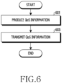
- FIG. 6 is a flowchart illustrating the operation of a base station according to various embodiments of the disclosure.
- FIG. 6 illustrates an operation method of the base station 101.
- the base station produces QoS information.
- the base station may produce QoS information according to the service of the transmitter or the receiver.
- the QoS information may be determined based on characteristics of the application to be used in the transmitter or the receiver.
- the QoS information may be produced in the form of an index representing a predefined QoS class.
- the base station transmits the QoS information.
- the QoS information may be transmitted to a corresponding terminal in the process of producing a bearer or flow of the terminal.
- the QoS information transmitted to the terminal may be used to determine whether or not packet duplication is performed.
- a transmitter or a receiver may receive QoS information from a base station through an RRC message. That is, a transmitter or a receiver in the service area of a base station may configure packet duplication in the same manner, based on the QoS information received from the base station through an RRC message.
- the transmitter or the receiver may receive QoS information from a higher layer according to a service type by itself using predetermined information, instead of receiving the QoS information from the base station, thereby processing the same.
- the transmitter and the receiver in the service area of the same base station may transmit and receive duplicated packets, based on the same packet duplication configuration received from the base station.
- transmission and reception of duplicated packets between a transmitter and a receiver, which belong to service areas of different base stations, or ii) transmission and reception of duplicated packets in the case where a transmitter performs handover while transmitting the duplicated packets may cause a problem because the transmitter and the receiver may have different packet duplication configurations received from the base stations.
- the disclosure proposes the following embodiments.
- the transmitter may determine a packet duplication configuration, based on service type or packet priority information, that is, a PPPP.
- the transmitter may transmit, to the receiver, information on packet duplication such as a service type, information configured for packet duplication, or duplication information configured in the transmitter.
- the receiver may receive a duplicate packet transmitted from the transmitter, based on the information on packet duplication determined and transmitted by the transmitter.
- packet duplication configuration may be different between base stations
- information on the packet duplication configuration of a target base station may be transmitted to the transmitter through handover signaling.
- packet duplication configuration i.e., information to determine whether or not to perform packet duplication or information on criteria for determining whether or not to perform packet duplication or the like
- the information on the packet duplication configuration may be included in a higher layer (e.g., RRC) message used for processing handover, or may be included in a separate message defined for packet duplication configuration.
- the terminal may perform different configurations regarding whether or not to perform packet duplication before and after handover.
- the transmitter may or may not perform packet duplication and transmission according to information preconfigured in the transmitter. According to another embodiment, the transmitter may determine whether or not to perform packet duplication according to the configuration before handover.
- a system may support device-to-device (D2D) communication that performs communication through a direct link between terminals.
- D2D communication is a communication method in which terminals establish a direct link therebetween and directly transmit and receive voice and data therebetween without passing through the base station.
- D2D communication may include schemes such as terminal-to-terminal communication, peer-to-peer communication, and the like.
- the D2D communication scheme may be applied to machine-to-machine (M2M) communication, machine-type communication (MTC), vehicle-to-everything (V2X), and the like.
- M2M machine-to-machine
- MTC machine-type communication
- V2X vehicle-to-everything
- D2D communication is considered as a way to solve the load of the base station due to sharply increasing data traffic.
- data may be exchanged between devices without passing through a base station, thereby reducing network overload.
- vehicle-to-everything (V2X) communication is under discussion as a form linked to D2D communication.
- V2X is a concept encompassing V2V communication between vehicle terminals, V2P communication between a vehicle and other types of terminals, and V2I communication between a vehicle and roadside units (RSUs).
- Various embodiments related to the execution of packet duplication described above may be performed by a transmitter and a receiver performing V2X communication.
- the above-described embodiments may be performed during V2X communication between terminals performing V2X communication using carrier aggregation.
- various embodiments related to V2X communication will be described.
- the embodiments described below are not limited to V2X communication, and may be applied to other types of communication.
- V2X f vehicle-to-everything (X) ⁇ indicates a pedestrian ⁇ communication between a vehicle and a device carried by an individual (e.g., a handheld terminal carried by a pedestrian, a cyclist, a driver, or a passenger) ⁇ (V2P), a vehicle (communication between vehicles) (V2V), infrastructure/network ⁇ communication between a vehicle and a roadside unit (RSU)/network, for example, RSU is a transportation infrastructure entity (e.g., an entity transmitting speed notifications) ⁇ (V2I/N), and the like.
- V2P vehicle ⁇ communication between vehicles
- V2V vehicle
- RSU roadside unit
- V2I/N roadside unit
- a device possessed by a pedestrian (or person) (related to V2P communication) will be referred to as a "P-terminal”
- a device installed in a vehicle (related to V2X communication) will be referred to as a "V-terminal” for the convenience of explanation of the proposed method.
- the term "entity” in the disclosure may be interpreted as a "P-terminal”, a “V-terminal”, and/or an "RSU (/network/infrastructure)".
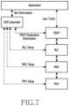
- FIG. 7 illustrates a logical hierarchy structure for packet duplication configuration in a packet data convergence protocol (PDCP) layer according to various embodiments of the disclosure.
- PDCP packet data convergence protocol
- a PDCP layer since a PDCP layer performs packet duplication, information related to packet duplication is transmitted to the PDCP layer, and layers lower than the PDCP layer operate in the same manner as in normal packet transmission.
- the layer in which to perform packet duplication may be determined by a V2X controller, which will be described later, may be determined by a base station, or may be determined in advance by a terminal.
- FIG. 7 may be applied to both a transmitter and a receiver.
- information and packets may be transmitted from a higher layer to a lower layer
- information and packets may be transmitted from a lower layer to a higher layer.
- a higher layer may define QoS information preconfigured according to a service type or information on a packet, for example, at least one of a source address, a destination address, or a port number of a packet.
- the QoS information may include at least one of a QCI, a packet delay budget, and a packet error loss rate.
- the V2X controller may be RRC for an LTE system, or may be a ProSe function for a sidelink.
- the application layer which is a higher layer than the V2X controller, may transmit a service type or QoS information, which is used in the application layer, to the V2X controller.
- the V2X controller may map parameters according to the QoS information or the service type received from the higher layer. As described above with reference to FIG. 4 , the parameter may be defined according to at least one of a PPPP and a PRPP.
- the PRPP determines whether or not to duplicate a packet, and may be expressed as a 1-bit flag or a constant value. In the case where the PRPP is a 1-bit flag, it is expressed as 0 or 1 to directly indicate the duplication or non-duplication of packets. For example, in the case where the packet error loss rate of the QoS transmitted from the application layer to the V2X controller is 10 -6 , the V2X controller may configure the PRPP as 1, thereby informing the layer in which to perform packet duplication, i.e., the PDCP layer, in the case of FIG. 7 , in which packet duplication is to be performed.
- the PRPP may reflect the packet error loss rate of the QoS.
- the V2X controller may express the PRPP as 10 -6 , thereby transmitting the same to the layer to perform packet duplication, i.e., the PDCP layer.
- the V2X controller may transmit, to the PDCP layer, a PRPP_threshold value, which is a threshold value, along with the PRPP.
- the PDCP layer may compare the PRPP with the PRPP_threshold received from the V2X controller, and if the PRPP is higher than the PRPP_threshold, may perform packet duplication.
- the V2X controller may provide PDCP duplication information as information for configuring packet duplication to the PDCP layer.
- the PDCP duplication information may include at least one of, for example, a bearer ID, a PRPP, or a PPPP.
- the bearer ID may include at least one of a radio bearer ID, a sidelink bearer ID, a Pc5 bearer ID, or a V2X data bearer ID.
- the PDCP duplication information is a message for configuring a PDCP layer, and may be transmitted from the V2X controller to the PDCP layer using an RRC message or predetermined information.
- the PDCP layer may perform PDCP layer configuration, for example, configuration of a radio bearer mapped to the PDCP layer using the information provided from the V2X controller.
- PDCP layer configuration for example, configuration of a radio bearer mapped to the PDCP layer using the information provided from the V2X controller.
- two RLC entities may be mapped to one PDCP entity.
- RLC, MAC, and PHY layers which are lower layers, may perform internal layer configuration by the V2X controller.
- FIG. 8 illustrates the configuration of a transmitter device for mapping two or more radio link control (RLC) entities to one PDCP entity according to various embodiments of the disclosure.
- RLC radio link control
- a packet may be transmitted to a PDCP entity through a radio bearer mapped to user traffic.
- the V2X controller determines whether or not the radio bearer requires PDCP packet duplication, and transmits the determination to a PDCP entity.
- the PDCP entity duplicates data transmitted through the radio bearer and transmits the same to two or more RLC entities using a radio bearer. Accordingly, a plurality of RLC entities is mapped to one PDCP entity according to the number of duplicated packets.
- Two or more RLC entities are mapped to a MAC layer through different respective logical channel IDs.
- Two or more different RLC entities are mapped to two or more different hybrid automatic repeat request (HARQ) entities in the MAC layer.
- Two or more different HARQ entities transmit respective data corresponding thereto through two or more different component carriers constituting carrier aggregation.
- HARQ hybrid automatic repeat request
- PDCP PDUs duplicated with respect to the same PDCP entity are submitted to two different RLC entities and are associated with two different sidelink logical channels, respectively.
- PDCP PDUs duplicated with respect to the same PDCP entity may be transmitted only through different sidelink carriers.
- the data transmitted from the PDCP entity by passing through RLC A via logical channel ID 1 is mapped to HARQ A
- the data transmitted from the PDCP entity by passing through RLC B via logical channel ID 2 is mapped to HARQ B.
- the data mapped to HARQ A is mapped to component carrier CC1, which is a component carrier in the PHY layer, to then be transmitted to a receiver
- the data mapped to HARQ B is mapped to component carrier CC2, which is a component carrier in the PHY layer, to then be transmitted to a receiver.
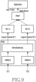
- FIG. 9 illustrates the configuration of a receiver device for mapping two or more radio link control (RLC) entities to one PDCP entity according to various embodiments of the disclosure.
- RLC radio link control
- the receiver device in FIG. 9 has a configuration corresponding to the transmitter device in FIG. 8 .
- two or more RLC entities are mapped to one PDCP entity.
- Data received by the receiver in CC 1 is transmitted to HARQ A, and data received in CC 2 is transmitted to HARQ B.
- the data transmitted through HARQ A and HARQ B is de-multiplexed in a MAC layer and is then transmitted to RLC A and RLC B through logical channel ID 1 and logical channel ID 2, respectively.
- the data transmitted to RLC A and RLC B is data duplicated with each other.
- the data transmitted to two or more RLC entities, RLC A, and RLC B, is transmitted to one PDCP entity.
- the PDCP entity receives and processes two or more pieces of duplicate data. Data processing of the PDCP entity is performed according to the order of reception of data from the respective RLC entities. For example, if data is received first through RLC A and then duplicate data is received through RLC B, the data received through RLC A is processed and transmitted to a higher layer, and the data received through RLC B is discarded.
- FIG. 10 illustrates parameters available in an LTE system among quality of service (QoS) parameters according to various embodiments of the disclosure.
- the parameters in FIG. 10 are QoS parameters currently used in the LTE system.
- the parameters shown in FIG. 10 constitute QoS information, and are used to produce a PRPP. Accordingly, the parameter in FIG. 10 is used to determine whether or not to duplicate a packet through a PRPP.
- QoS information is mapped to QCI and used in an access stratum (AS) layer.
- AS access stratum
- the QCI is determined based on a resource type, a priority level, a packet delay budget, and a packet error loss rate.
- the packet error loss rate in the case of a real time gaming as an example service is 10 -3
- the packet error loss rate in the case of a V2X message is 10 -2 . Since the packet error loss rate in the real time gaming is lower when comparing the two services, packet duplication may be performed on the real time gaming.
- FIG. 11 illustrates parameters available in a 5G system, among QoS parameters, according to various embodiments of the disclosure.
- the parameters in FIG. 11 are QoS parameters currently used in a 5G new radio (NR) system.
- NR new radio
- the parameters in FIG. 11 also constitute QoS information and are used in producing a PRPP.
- the QoS information is mapped to a 5G QoS identifier (5QI) and used in an AS layer.
- 5CI is determined by a resource type, a priority level, a packet delay budget, a packet error loss rate, and a default averaging window.
- the packet error loss rate in the case of a conversational video as an example of served content is 10 -3
- the packet error loss rate in the case of a non-conversational video is 10 -6 . Since the packet error loss rate of the non-conversational video is lower when comparing the two services, packet duplication may be performed on the non-conversational video.
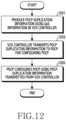
- FIG. 12 is a flowchart illustrating an operation of configuring PDCP duplication in a transmitter/receiver according to various embodiments of the disclosure.
- a V2X controller may produce PDCP duplication information using QoS information received from a higher application layer, for example, a packet error loss rate or the like (1201).
- the V2X controller may provide a PDCP layer with PDCP duplication information for configuring packet duplication (1203).
- the PDCP duplication information may include, for example, at least one of a bearer ID, a PRPP, or a PPPP.
- the bearer ID may include at least one of a radio bearer ID, a sidelink bearer ID, a PC5 bearer ID, and a V2X data bearer ID.
- the PRPP may be represented by a flag of 1 bit or a constant value. In the case where the PRPP is a 1-bit flag, it directly indicates the duplication or non-duplication of packets.
- the V2X controller may transmit, to the PDCP layer, a PRPP_threshold value, which is a threshold value, along with the PRPP.
- the PDCP layer may compare the PRPP with the PRPP_threshold received from the V2X controller, and if the PRPP is higher than the PRPP_threshold, may perform packet duplication.
- the V2X controller may provide PDCP duplication information for configuring packet duplication to the PDCP layer.
- the PDCP layer may configure the PDCP layer using information provided from the V2X controller (1205). For example, if packet duplication is determined through PDCP duplication information, two RLC entities are mapped to one PDCP entity. Therefore, two or more logical channels may be mapped to each radio bearer ID.
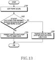
- FIG. 13 is a flowchart illustrating an operation of performing duplication in a PDCP layer after user traffic occurs in a transmitter according to various embodiments of the disclosure.
- the application layer which is a higher layer, may transmit user traffic as data to the PDCP layer.
- the PDCP layer receives a packet in which user traffic occurs from a higher layer or activates a radio bearer (1301).
- the PDCP entity may identify the packet produced in the higher layer or the radio bearer activated by the higher layer, and may then identify whether or not to perform packet duplication (1303).
- the radio bearer is preconfigured by a V2X controller.
- one PDCP entity transmits the same data to two or more RLC entities (1305).
- one PDCP entity is mapped to one RLC entity and transmits data thereto (1307).
- FIG. 14 is a flowchart illustrating an operation of performing duplication in a PDCP layer after user traffic occurs in a receiver according to various embodiments of the disclosure.
- the operation flow of the receiver in FIG. 14 corresponds to the operation flow of the transmitter in FIG. 13 .
- the PDCP layer receives data from a lower layer, e.g., an RLC layer (1401).
- a lower layer e.g., an RLC layer (1401).
- the PDCP may identify whether or not PDCP packet duplication has been performed on the packet (1403).
- the configuration of a duplicate logical channel or non-duplicate logical channel is performed in advance by a V2X controller.
- the PDCP processes the duplicate packet and transmits the same to a higher layer (1405). For example, reordering may be performed using the duplicate packet.
- the PDCP may process the non-duplicate packet, and may then transmit the same to a higher layer, for example, an application layer (1407).
- packet duplication detection is performed in the PDCP layer in the receiver.
- the reordering function is also supported in the PDCP layer, and a method of configuring a reordering timer in the PDCP layer depends on the implementation of the receiver.
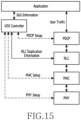
- FIG. 15 illustrates a logical hierarchy structure for configuring packet duplication in an RLC layer according to various embodiments of the disclosure.
- a higher layer may define QoS information preconfigured according to a service type or information on a packet, for example, at least one of a source address, a destination address, or a port number of a packet.
- the QoS information may include at least one of a QCI, a packet delay budget, and a packet error loss rate, and may be mapped to the parameters in FIG. 10 or 11 .
- the V2X controller may be RRC for an LTE system, or may be a ProSe function for a sidelink.
- the application layer which is a higher layer than the V2X controller, may transmit a service type or QoS information, which is used in the application layer, to the V2X controller.
- the V2X controller may map parameters according to the QoS information or the service type received from the higher layer. As described above with reference to FIG. 4 , the parameter may be defined according to at least one of a PPPP or a PRPP, or a V-UM (unacknowledged mode) RLC window timer or a logical channel ID value, which will be described later.
- the PRPP determines whether or not to duplicate a packet, and may be expressed as a 1-bit flag or a constant value. In the case where the PRPP is a 1-bit flag, it directly indicates the duplication or non-duplication of packets. In the case where the PRPP is a constant value, the PRPP may reflect a packet error loss rate. In the case where the packet error loss rate of the QoS transmitted from the application layer to the V2X controller is 10 -6 , the V2X controller may express the PRPP as 10 -6 , thereby transmitting the same. In the case where the PRPP is a constant value, the V2X controller may transmit, to the PDCP layer, a PRPP_threshold value, which is a threshold value, along with the PRPP. The PDCP layer may compare the PRPP with the PRPP_threshold received from the V2X controller, and if the PRPP is higher than the PRPP_threshold, may perform packet duplication.
- V2X Since V2X is based on broadcast, it is impossible to introduce acknowledgment (Ack) feedback. Therefore, V2X can use only a UM mode, instead of an acknowledgement mode (AM) mode including Ack, in the RLC retransmission method.
- the disclosure proposes a method of operating a window as if it were in an AM mode even though it is in a UM mode. Specifically, the window in the AM mode moves based on the packet having the earliest number, among the packets that have not been received. However, in the case of using a window in the AM mode in V2X, the window may not move continuously because Ack feedback is not received. Therefore, the disclosure proposes that a timer is defined and that if the timer expires, the window is forcibly moved.
- the expiration time of the timer may be configured according to a PPPP in consideration of the delay. Therefore, if the priority is high, the timer may be configured to be short, and the window may be moved quickly.
- a new timer in the UM for V2X is defined as a "V_UM RLC window timer”.
- a window operating as if it were in an AM mode according to the V_UM RLC window timer is defined as a "V_UM RLC window”.
- a new RLC UM operation using a V_UM RLC window timer for V2X is defined as a "V_UM RLC operation".
- the PPPP may be provided as a parameter for configuring the V_UM RLC window timer.
- the value of the timer may be configured according to an index value of the PPPP. For example, if the PPPP index is 1, the V_UM RLC window timer may be configured as 100 ms. If the PPPP index is 2, the V_UM RLC window timer may be configured as 200 ms.
- the V2X controller may provide RLC duplication information for configuring packet duplication to the RLC.
- the RLC duplication information may include, for example, at least one of a bearer ID, a PRPP, a PPPP, an LCID, or V_UM RLC window timer.
- the bearer ID may include at least one of a radio bearer ID, a sidelink bearer ID, a Pc5 bearer ID, or a V2X data bearer ID.
- the RLC duplication information is a message for configuring an RLC layer, and may be transmitted from the V2X controller to an RLC layer using an RRC message or predetermined information.
- the RLC layer may perform configuration between a PDCP layer and an RLC layer using the RLC duplication information provided by the V2X controller. For example, in the case where RLC packet duplication is performed using a method determined by a V2X controller, determined by a base station, or determined by a terminal in advance, two or more logical channel IDs may be mapped to one RLC entity. Accordingly, the PDCP, MAC, and PHY layers may be configured by a method of processing a packet in an LTE system as an example of configuration.
- FIG. 16 illustrates the configuration of a transmitter device that maps two or more logical channel IDs to one RRC entity according to various embodiments of the disclosure.
- a packet may be transmitted to the PDCP through a radio bearer mapped to the user traffic.
- the PDCP layer transmits the packet to an RLC entity.
- the RLC entity may perform the V_UM RLC operation defined in FIG. 15 . A detailed description of the V_UM RLC operation will be made later with reference to FIG. 18 .
- the V2X controller determines whether or not packet duplication of the data from the PDCP is to be performed. Accordingly, the data received through a corresponding to radio bearer is mapped to two or more logical channel IDs through the RLC and is transmitted to the MAC layer.
- Two or more different logical channel IDs are mapped to two or more different HARQs in the MAC layer.
- Two or more different HARQ entities transmit respective corresponding data through two or more different component carriers constituting carrier aggregation.
- data received through logical channel 1 is mapped to HARQ A
- data received through logical channel 2 is mapped to HARQ B.
- HARQ A is mapped to CC 1 to then be transmitted in the PHY layer
- HARQ B is mapped to CC 2 to then be transmitted.
- CC 1 and CC 2 are component carriers that perform carrier aggregation together.
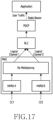
- FIG. 17 illustrates the configuration of a receiver device that maps two or more logical channel IDs to one RRC entity according to various embodiments of the disclosure.
- the receiver device in FIG. 17 has a configuration corresponding to the transmitter device in FIG. 16 .
- two or more logical channels are mapped to one RLC entity.
- Data received by the receiver in CC 1 is transmitted to HARQ A, and data received in CC 2 is transmitted to HARQ B.
- the data transmitted through HARQ A and HARQ B is de-multiplexed in a MAC layer and is then transmitted to one RLC through logical channel ID 1 and logical channel ID 2.
- Two or more pieces of duplicate data received through one RLC are transmitted to the PDCP entity via reordering.
- the data received by the PDCP entity is processed by a higher method and is then transmitted to the higher layer.
- FIG. 18 is a flowchart illustrating an operation of operating an RLC window and an RLC window timer in a receiver device during RLC duplication according to various embodiments of the disclosure.
- An RLC entity may configure a V_UM RLC window timer according to information received through a V2X controller (1801).
- the PPPP may indicate a priority index, and may map the PPPP index to a value of the V_UM RLC window timer. For example, if the PPPP index is 1, the V_UM RLC window timer may be configured as 100 ms, and if the PPPP index is 2, the V_UM RLC window timer may be configured as 200 ms.
- the RLC entity may apply the value of the received V_UM RLC window timer as it is.
- the RLC entity receives the packet (1803), and may operate as follows depending on the reception state of the packet.
- the V_UM RLC window is moved to the packet having the earliest packet number, among the packets that have not been received (1811), the V_UM RLC window timer is started (1813), and the RLC packet is received again.
- the V_UM RLC window is moved to the packet subsequent to the packet that has not been received based on the earliest packet number, among the packets that have not been received (1815), the V_UM RLC window timer is started (1813), and the RLC packet is received again.
- the V_UM RLC window is moved to the packet having the earliest packet number, among the packets that have not been received (1811), the V_UM RLC window timer is started (1813), and the RLC packet is received again.
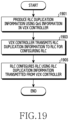
- FIG. 19 is a flowchart illustrating an operation of configuring RLC duplication in a transmitter/receiver according to various embodiments of the disclosure.
- a V2X controller may produce RLC duplication information using QoS information received from a higher application layer, for example, a packet error loss rate or the like (1901).
- the V2X controller may provide a RLC layer with RLC duplication information for configuring packet duplication (1903).
- the RLC duplication information may include, for example, at least one of a bearer ID, a PRPP, a PPPP, or a V_UM window timer.
- the bearer ID may include at least one of a radio bearer ID, a sidelink bearer ID, a PC5 bearer ID, or a V2X data bearer ID.
- the PRPP may be represented by a flag of 1 bit or a constant value. In the case where the PRPP is a 1-bit flag, it directly indicates the duplication or non-duplication of packets. In addition, in the case where the PRPP is a constant value, the PRPP may reflect a packet error loss rate. In the case where the packet error loss rate of the QoS transmitted from the application layer to the V2X controller is 10 -6 , the V2X controller may express the PRPP as 10 -6 , thereby transmitting the same. In the case where the PRPP is a constant value, the V2X controller may transmit, to the PDCP layer, a PRPP_threshold value, which is a threshold value, along with the PRPP. The PDCP layer may compare the PRPP with the PRPP_threshold received from the V2X controller, and if the PRPP is higher than the PRPP_threshold, may perform packet duplication.
- the PPPP may be represented as an index, or may be represented as a value of the V_UM RLC window timer corresponding to the PPPP, instead of the PPPP.
- the V2X controller may provide RLC duplication information for configuring packet duplication in the RLC layer.
- the RLC layer may configure the RLC layer using information provided from the V2X controller (1905). For example, if packet duplication is determined through RLC duplication information, two or more logical channel IDs may be mapped to one RLC entity.
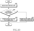
- FIG. 20 is a flowchart illustrating an operation of processing a duplicate packet in an RLC layer after user traffic occurs in a transmitter according to various embodiments of the disclosure.
- the RLC layer receives a packet from a higher layer, for example, a PDCP layer (2001).
- the RLC layer may identify an internal radio bearer from the PDCP, and may identify whether or not to perform RLC duplication (2003).
- the internal radio bearer may be preconfigured by the V2X controller.
- one RLC entity transmits the same data through two or more logical channel IDs (2005).
- one RLC entity is mapped to one logical channel to then transmit data (2007).
- FIG. 21 is a flowchart illustrating an operation of processing a duplicated packet in an RLC layer after user traffic occurs in a receiver according to various embodiments of the disclosure.
- the operation flow of the receiver in FIG. 21 corresponds to the operation flow of the transmitter in FIG. 20 .
- the RLC layer receives data from a lower layer, e.g., a MAC layer (2101).
- a lower layer e.g., a MAC layer (2101).
- the RLC may identify whether or not RLC packet duplication has been performed on the packet (2103).
- the configuration of a duplicate logical channel or non-duplicate logical channel is performed in advance by a V2X controller.
- the RLC may process the data according to the V_UM RLC window operation method in FIG. 18 (2105). Specifically, the packets may be reordered according to the V_UM RLC window operation method in FIG. 18 .
- the RLC may process the non-duplicate packet, and may then transmit the same to a higher layer, for example, the PDCP layer (2107).
- FIG. 22 illustrates a logical hierarchy structure for configuring packet duplication in a PHY/MAC layer according to various embodiments of the disclosure.
- a higher layer may define QoS information preconfigured according to a service type or information on a packet, for example, at least one of a source address, a destination address, or a port number of a packet.
- the QoS information may include at least one of a QCI, a packet delay budget, and a packet error loss rate, and may be mapped to the parameters in FIG. 10 or 11 .
- the V2X controller may be RRC for an LTE system, or may be a ProSe function for a sidelink.
- the application layer which is a higher layer than the V2X controller, may transmit a service type or QoS information, which is used in the application layer, to the V2X controller.
- the V2X controller may map parameters according to the QoS information or the service type received from the higher layer.
- the parameter may be defined based on a PPPP or a PRPP.
- the PRPP determines whether or not to duplicate a packet, and may be expressed as a 1-bit flag or a constant value. In the case where the PRPP is a 1-bit flag, it directly indicates the duplication or non-duplication of packets. In the case where the PRPP is a constant value, the PRPP may reflect a packet error loss rate. In the case where the packet error loss rate of the QoS transmitted from the application layer to the V2X controller is 10 -6 , the V2X controller may express the PRPP as 10 -6 , thereby transmitting the same. In the case where the PRPP is a constant value, the V2X controller may transmit, to the PDCP layer, a PRPP_threshold value, which is a threshold value, along with the PRPP. The PDCP layer may compare the PRPP with the PRPP_threshold received from the V2X controller, and if the PRPP is higher than the PRPP_threshold, may perform packet duplication.
- the V2X controller may provide PHY/MAC duplication information for MAC to configure packet duplication to the MAC.
- the PHY/MAC duplication information for MAC may include, for example, at least one of a logical channel ID or a HARQ ID.
- the PHY/MAC duplication information for MAC is a message for configuring the MAC, and may be transmitted from the V2X controller to the MAC layer using an RRC message or predetermined information.
- the MAC layer may perform MAC configuration using the PHY/MAC duplication information for MAC provided by the V2X controller. For example, in the case where PHY/MAC packet duplication is performed using a method determined by a V2X controller, determined by a base station, or determined in advance by a terminal, one HARQ ID may be mapped to one logical channel ID in the MAC entity.
- the V2X controller may provide PHY/MAC duplication information for PHY to configure packet duplication to the PHY.
- the PHY/MAC duplication information for PHY may include, for example, at least one of a HARQ ID or a component carrier ID.
- the PHY/MAC duplication information for PHY is a message for configuring the PHY, and may be transmitted from the V2X controller to the PHY layer using an RRC message or predetermined information.
- the PHY layer may perform PHY configuration using the PHY/MAC duplication information for PHY provided by the V2X controller. For example, in the case where PHY/MAC packet duplication is performed using a method determined by a V2X controller, determined by a base station, or determined in advance by a terminal, one HARQ ID may be mapped to two or more component carriers in the PHY layer.
- FIG. 23 illustrates the structure of a transmitter device that maps two or more component carriers to one hybrid automatic repeat request (HARQ) entity according to various embodiments of the disclosure.
- HARQ hybrid automatic repeat request
- a packet may be transmitted to the PDCP through a radio bearer mapped to the user traffic.
- the PDCP layer transmits the packet to an RLC entity.
- the RLC entity is mapped to one HARQ in the MAC layer using a logical channel.
- the data received in the RLC is mapped to HARQ.
- the HARQ is mapped to two component carriers CC 1 and CC 2 in the PHY layer and is then be transmitted.
- CC 1 and CC 2 are component carriers that perform carrier aggregation together.
- the HARQ and the component carriers are configured by the V2X controller.
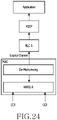
- FIG. 24 illustrates the structure of a receiver device that maps two or more component carriers to one hybrid automatic repeat request (HARQ) entity according to various embodiments of the disclosure.
- HARQ hybrid automatic repeat request
- the receiver device in FIG. 24 has a configuration corresponding to the transmitter device in FIG. 23 .
- two or more component carriers are mapped to one HARQ entity.
- a packet is transmitted to the HARQ mapped to a component carrier.
- the HARQ is mapped to two component carriers CC 1 and CC 2 in the PHY layer to enable HARQ combination.
- the data received through the HARQ is transmitted to a higher layer.
- FIG. 25 is a flowchart illustrating an operation of configuring PHY/MAC duplication in a transmitter/receiver according to various embodiments of the disclosure.
- a V2X controller may produce PHY/MAC duplication information for MAC and PHY/MAC duplication information for PHY using QoS information received from a higher application layer, for example, a packet error loss rate or the like (2501).
- the V2X controller may provide a MAC layer and a PHY layer with PHY/MAC duplication information for MAC and PHY/MAC duplication information for PHY, respectively (2503).
- the PHY/MAC duplication information for MAC may include, for example, at least one of a logical channel ID or a HARQ ID.
- the PHY/MAC duplication information for PHY may include, for example, at least one of a HARQ ID or one or more component carrier IDs.
- the PRPP may be represented by a flag of 1 bit or a constant value. In the case where the PRPP is a 1-bit flag, it directly indicates the duplication or non-duplication of packets. In addition, in the case where the PRPP is a constant value, the PRPP may reflect a packet error loss rate. In the case where the packet error loss rate of the QoS transmitted from the application layer to the V2X controller is 10 -6 , the V2X controller may express the PRPP as 10 -6 , thereby transmitting the same. In the case where the PRPP is a constant value, the V2X controller may transmit, to the PDCP layer, a PRPP_threshold value, which is a threshold value, along with the PRPP. The PDCP layer may compare the PRPP with the PRPP_threshold received from the V2X controller, and if the PRPP is higher than the PRPP_threshold, may perform packet duplication.
- the PPPP may be represented as an index, or may be represented as a value of a timer corresponding to the PPPP, instead of the PPPP.
- the V2X controller may provide PHY/MAC duplication information for MAC to configure packet duplication to the MAC layer.
- the MAC layer may map a logical channel to a HARQ ID using PHY/MAC duplication information for MAC provided by the V2X controller (2505). For example, if packet duplication is determined through the PHY/MAC duplication information for MAC, one HARQ ID may be mapped to one logical channel ID in the MAC.
- the V2X controller may provide PHY/MAC duplication information for PHY to configure packet duplication in the PHY layer.
- the PHY layer may configure a component carrier mapped to the HARQ ID using PHY/MAC duplication information for PHY provided by the V2X controller (2505). For example, if packet duplication is determined through a PRPP in the PHY/MAC, two or more component carrier IDs may be mapped to one HARQ entity.
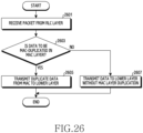
- FIG. 26 is a flowchart illustrating an operation of processing a duplicate packet in a PHY/MAC layer after user traffic occurs in a transmitter according to various embodiments of the disclosure.
- the MAC layer receives data from a higher layer, e.g., an RLC layer (2601). After checking a logical channel received from the RLC, the MAC layer may identify whether or not to perform MAC duplication (2603).
- a duplicate logical channel and a non-duplicate logical channel may be preconfigured by a V2X controller.
- the MAC transmits the same data to two or more component carriers in one HARQ entity (2605). On the other hand, if the MAC entity does not perform packet duplication, the MAC transmits data by mapping one HARQ entity to one component carrier (2607).
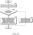
- FIG. 27 is a flowchart illustrating an operation of processing a duplicate packet in a PHY/MAC layer after user traffic occurs in a receiver according to various embodiments of the disclosure.
- the operation flow of the receiver in FIG. 27 corresponds to the operation flow of the transmitter in FIG. 26 .
- the PHY layer receives data via a wireless section (2701).
- the MAC may identify whether or not MAC packet duplication has been performed on the packet (2703).
- configuration of the component carrier is performed in advance by the V2X controller.
- the data is a MAC duplicate packet
- duplicated packets received through duplicate carriers are processed with HARQ combination, and the processed data is transmitted to a higher layer (2705).
- the data is not a MAC duplicate packet, the data is processed according to non-duplicate packet, and is then transmitted to, for example, the MAC/RLC/PDCP layer (2707).
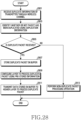
- FIG. 28 is a flowchart illustrating an operation in which a receiver processes a duplicate packet using duplication information transmitted from a transmitter according to various embodiments of the disclosure.
- Tables 1 to 3 and FIG. 28 show other embodiments of a configuration method for transmitting/receiving duplicate data, and relate to a method in which a transmitter provides notification of duplication or non-duplication through a wireless control channel and a method in which a receiver receives notification of duplication or non-duplication and configures a corresponding layer for processing packet duplication.
- the method described below may be applied to all of the PDCP duplication, the RLC duplication, and the MAC/PHY duplication described above.
- Table 1 shows a configuration of V2X Sidelink control information indicating location information of resources and decoding information of data to be transmitted in the case of using a sidelink channel. Respective fields are configured as follows.
- the resource reservation, the frequency resource location, and the MCS are control information indicating the resource to transmit data.
- the control information may be referred to as “sidelink control information (SCI)", and is periodically transmitted from a transmitter to a receiver through a physical downlink sidelink control channel (PDSCCH).
- SCI sidelink control information
- PDSCCH physical downlink sidelink control channel
- Table 2 shows a packet duplication indicator to indicate information on packet duplication, in addition to the control information in Table 1.
- the packet duplication indicator is represented by a bitmap.
- a carrier-packet duplication indicator may indicate whether or not the corresponding data is duplicate data.
- the carrier-packet duplication indicator may be represented by a bitmap.
- the bitmap may be represented by the number of bits equal to the number of carriers.
- the bitmap may be configured in ascending order of the carrier number from the left side thereof. That is, the first bit from the left of the bitmap may correspond to a first carrier.
- the bitmap may be configured in ascending order of the carrier number from the right side thereof. That is, the first bit from the right of the bitmap may correspond to a first carrier. If a bit value is configured as 0, it may indicate that packet duplication has not been performed on the corresponding carrier. If a bit value is configured as 1, it may indicate that packet duplication has been performed on the corresponding carrier. For example, if the bitmap is 000000, it means that no packet duplication has been performed on any carrier. In addition, for example, if the bitmap is 101000, it means that packets of the corresponding data are duplicated and transmitted in a first component carrier and a third component carrier.
- the transmitter may configure information on whether or not the packet is duplicated and information on a carrier in which the packet is duplicated using the bitmap field in Table 2, and may transmit control information on the packet to be transmitted to the receiver.
- the receiver may obtain the information on whether or not the packet is duplicated and the information on a carrier in which the packet is duplicated, and may receive and process the data according to the field value.
- bitmap field in Table 2 may be inserted as a new field into a MAC header of the data, instead of the sidelink control information.
- Table 3 Carrier-packet duplication (Multiple-original) Carrier index
- Table 3 shows a packet duplication indicator to indicate information on packet duplication in addition to the control information in Table 1.
- the packet duplication indicator is represented as a carrier index.
- a carrier-packet duplication indicator in Table 3 may indicate whether or not the corresponding data is duplicate data.
- a carrier index may be indicated by the carrier-packet duplication indicator.
- the carrier index may be represented as the number of bits representing the number of carriers, and may be represented using three bits in the case where eight component carriers are operated.
- the carrier index may include multiple-original and multiple-duplicate. For example, if control information that does not include multiple-original and multiple-duplicate is received, it indicates the transmission of data that is not duplicated. In addition, for example, if the index of multiple-original is 1 and if the index of multiple-duplicate is 3, this indicates data of which the packet is duplicated and transmitted in a first component carrier and a third component carrier.
- the transmitter may configure information on whether or not the packet is duplicated and information on the carrier in which the packet is duplicated using the fields in Table 3, and may transmit control information on the packet to be transmitted.
- the receiver may obtain the information on whether or not the packet is duplicated and the information on the carrier in which the packet is duplicated, and may receive and process the data according to the field values.
- the transmitter transmits control information that does not include the fields proposed in Tables 2 and 3, it may indicate that packet duplication is not performed.
- the receiver may identify that packet duplication is not performed.
- FIG. 28 is a diagram illustrating a method in which a receiver processes a duplicate packet using duplication information, such as SCI, transmitted from a transmitter.
- the receiver may receive duplication information, for example, SCI information, from the transmitter through a wireless section (2801).
- the duplication information may be any one of Tables 1 to 3.
- the transmitter may identify whether or not the received data is a duplicate packet through the duplication information received from the transmitter (2803).
- the receiver may recognize whether or not the received data is a duplicate packet through the fields in Tables 2 and 3 (2805).
- the receiver may operate as follows:
- component carrier 1 and component carrier 3 are mapped to RLC A and RLC B, and RLC A and RLC B are mapped to the PDCP.
- the receiver may operate as follows:
- the receiver performs a non-duplicate packet processing operation
- a computer-readable storage medium for storing one or more programs (software modules) may be provided.
- the one or more programs stored in the computer-readable storage medium may be configured for execution by one or more processors within the electronic device.
- the at least one program may include instructions that cause the electronic device to perform the methods according to various embodiments of the disclosure as defined by the appended claims and/or disclosed herein.
- the programs may be stored in non-volatile memories including a random access memory and a flash memory, a Read Only Memory (ROM), an Electrically Erasable Programmable Read Only Memory (EEPROM), a magnetic disc storage device, a Compact Disc-ROM (CD-ROM), Digital Versatile Discs (DVDs), or other type optical storage devices, or a magnetic cassette.
- ROM Read Only Memory
- EEPROM Electrically Erasable Programmable Read Only Memory
- CD-ROM Compact Disc-ROM
- DVDs Digital Versatile Discs
- any combination of some or all of the may form a memory in which the program is stored. Further, a plurality of such memories may be included in the electronic device.
- the programs may be stored in an attachable storage device which is accessible through communication networks such as the Internet, Intranet, local area network (LAN), wide area network (WAN), and storage area network (SAN), or a combination thereof.
- a storage device may access the electronic device via an external port.
- a separate storage device on the communication network may access a portable electronic device.
- a component included in the disclosure is expressed in the singular or the plural according to a presented detailed embodiment.
- the singular form or plural form is selected for convenience of description suitable for the presented situation, and various embodiments of the disclosure are not limited to a single element or multiple elements thereof. Further, either multiple elements expressed in the description may be configured into a single element or a single element in the description may be configured into multiple elements.
Landscapes
- Engineering & Computer Science (AREA)
- Computer Networks & Wireless Communication (AREA)
- Signal Processing (AREA)
- Quality & Reliability (AREA)
- Mobile Radio Communication Systems (AREA)
Claims (12)
- Procédé pour faire fonctionner un émetteur dans un système de communication sans fil, le procédé comprenant :déterminer un paramètre indiquant une fiabilité par paquet de ProSe (service de proximité), PPPR, d'un paquet pour un service de véhicule à tout, V2X, où la PPPR indique un niveau de fiabilité requis pour le paquet selon un type de service de V2X du service de V2X, où la PPPR est définie par une couche d'application ;dans le cas où le paramètre serait supérieur ou égal à un seuil de PPPR configuré, dupliquer le paquet ; ettransmettre, à un deuxième dispositif électronique du service de V2X, le paquet via une première porteuse de composant et le paquet dupliqué via une deuxième porteuse de composant, où la première porteuse de composant et la deuxième porteuse de composant sont configurées pour une agrégation de porteuses.
- Procédé selon la revendication 1, où la valeur de seuil de PPPR est préconfigurée.
- Procédé selon la revendication 1, où la valeur de seuil de PPPR est obtenue à travers un message de configuration.
- Procédé selon la revendication 1, où, dans le cas où le paquet serait dupliqué, deux canaux logiques différents sont mappés à un support radio.
- Procédé selon la revendication 1, où le paramètre est identifié en outre sur la base d'informations de qualité de service, QoS.
- Procédé pour faire fonctionner un récepteur dans un système de communication sans fil, le procédé comprenant :recevoir, à partir d'un émetteur d'un service de véhicule à tout, V2X, un premier paquet à travers une première porteuse de composant et un deuxième paquet à travers une deuxième porteuse de composant, où la première porteuse de composant et la deuxième porteuse de composant sont configurées pour une agrégation de porteuses ;déterminer si le premier paquet et le deuxième paquet sont des paquets dupliqués, où le premier paquet et le deuxième paquet sont dupliqués dans le cas où la fiabilité par paquet de ProSe (service de proximité), PPPR, du premier paquet pour le service de V2X serait supérieure ou égale à un seuil de PPPR configuré, où la PPPR indique un niveau de fiabilité requis pour le paquet selon un type de service de V2X du service de V2X, où la PPPR est définie par une couche d'application ;lorsqu'il est déterminé que le premier paquet et le deuxième paquet sont des paquets dupliqués, effectuer un réordonnancement de paquets.
- Procédé selon la revendication 6, comprenant en outre, lorsqu'il est déterminé que le premier paquet et le deuxième paquet sont des paquets dupliqués, rejeter un paquet comprenant des données qui sont déjà reçues parmi le premier paquet et le deuxième paquet.
- Procédé selon la revendication 6, où si le premier paquet et le deuxième paquet sont des paquets dupliqués est déterminé en identifiant les canaux logiques du premier paquet et du deuxième paquet.
- Procédé selon la revendication 6, où le premier paquet et le deuxième paquet ont deux identifiants de canal logique différents et comprennent les mêmes données.
- Procédé selon la revendication 6, où, dans le cas où le premier paquet et le deuxième paquet seraient des paquets dupliqués, deux canaux logiques différents sont mappés à un support radio.
- Émetteur configuré pour mettre en oeuvre le procédé de l'une quelconque des revendications 1 à 5.
- Récepteur configuré pour mettre en oeuvre le procédé de l'une quelconque des revendications 6 à 10.
Applications Claiming Priority (2)
| Application Number | Priority Date | Filing Date | Title |
|---|---|---|---|
| KR1020170125359A KR102435428B1 (ko) | 2017-09-27 | 2017-09-27 | 무선 통신 시스템에서 패킷을 전송하기 위한 방법 및 장치 |
| PCT/KR2018/011151 WO2019066386A1 (fr) | 2017-09-27 | 2018-09-20 | Procédé et appareil de transmission de paquet dans un système de communication sans fil |
Publications (3)
| Publication Number | Publication Date |
|---|---|
| EP3672318A1 EP3672318A1 (fr) | 2020-06-24 |
| EP3672318A4 EP3672318A4 (fr) | 2020-09-02 |
| EP3672318B1 true EP3672318B1 (fr) | 2023-02-22 |
Family
ID=65902083
Family Applications (1)
| Application Number | Title | Priority Date | Filing Date |
|---|---|---|---|
| EP18860250.2A Active EP3672318B1 (fr) | 2017-09-27 | 2018-09-20 | Procédé et appareil de transmission de paquet dans un système de communication sans fil |
Country Status (5)
| Country | Link |
|---|---|
| US (2) | US11178569B2 (fr) |
| EP (1) | EP3672318B1 (fr) |
| KR (1) | KR102435428B1 (fr) |
| CN (1) | CN111149383B (fr) |
| WO (1) | WO2019066386A1 (fr) |
Families Citing this family (15)
| Publication number | Priority date | Publication date | Assignee | Title |
|---|---|---|---|---|
| EP4114112A1 (fr) | 2017-01-13 | 2023-01-04 | Samsung Electronics Co., Ltd. | Procédé et dispositif de transmission de paquet de données dans un système de communication sans fil |
| KR102435428B1 (ko) * | 2017-09-27 | 2022-08-24 | 삼성전자주식회사 | 무선 통신 시스템에서 패킷을 전송하기 위한 방법 및 장치 |
| KR102657514B1 (ko) * | 2018-02-13 | 2024-04-16 | 삼성전자주식회사 | 무선 통신 시스템에서 복제된 데이터를 송수신하기 위한 방법 및 장치 |
| ES2917600T3 (es) * | 2018-03-29 | 2022-07-11 | Fraunhofer Ges Forschung | Calidad de servicio mejorada para V2X |
| CN110324195B (zh) * | 2018-03-30 | 2021-01-08 | 维沃移动通信有限公司 | 一种接收方法、发送方法及通信设备 |
| DE102018206785A1 (de) * | 2018-05-03 | 2019-11-07 | Audi Ag | Datenübertragung mittels des Bluetooth Low Energy (BLE)-Standards |
| CN112292895A (zh) * | 2018-08-10 | 2021-01-29 | 富士通株式会社 | 一种通信方法、装置和通信系统 |
| CN110876168B (zh) * | 2018-08-31 | 2021-08-03 | 华为技术有限公司 | 一种数据传输方法、相关设备、装置及相关系统 |
| CN110958090B (zh) * | 2018-09-27 | 2021-09-14 | 维沃移动通信有限公司 | PDCP duplication的配置方法和终端设备 |
| CN112703710B (zh) * | 2018-09-28 | 2023-05-23 | Oppo广东移动通信有限公司 | 数据传输方法、发射端设备和接收端设备 |
| US11483732B2 (en) * | 2018-10-05 | 2022-10-25 | T-Mobile Usa, Inc. | Intelligent allocation of network resources |
| JP7199540B2 (ja) * | 2018-12-14 | 2023-01-05 | オッポ広東移動通信有限公司 | データ処理の方法、機器および記憶媒体 |
| US20220159674A1 (en) * | 2019-02-22 | 2022-05-19 | Idac Holdings, Inc. | Methods for nr sl multi-sub-channel pscch transmission |
| WO2022047742A1 (fr) * | 2020-09-04 | 2022-03-10 | Arris Enterprises Llc | Amélioration de performance de jeu pour dispositif à double connexion wi-fi |
| CN115884392A (zh) * | 2021-09-26 | 2023-03-31 | 维沃移动通信有限公司 | Md传输方法、设备及可读存储介质 |
Family Cites Families (43)
| Publication number | Priority date | Publication date | Assignee | Title |
|---|---|---|---|---|
| KR100582732B1 (ko) * | 2005-01-31 | 2006-05-22 | 삼성전자주식회사 | 멀티캐스트 패킷 포워딩 장치 및 그 방법 |
| TWI299620B (en) * | 2005-04-05 | 2008-08-01 | Innovative Sonic Ltd | Method and related apparatus for reconfiguring size of a receiving window in a communication system |
| JP5092350B2 (ja) * | 2006-10-26 | 2012-12-05 | 富士通株式会社 | パイロット信号伝送方法及び移動通信システム |
| US8374271B2 (en) * | 2007-01-08 | 2013-02-12 | Cisco Technology, Inc. | Method and system for resizing a MIMO channel |
| US8165228B2 (en) * | 2007-03-20 | 2012-04-24 | Alcatel Lucent | Non-coherent transmission method for uplink control signals using a constant amplitude zero-autocorrelation sequence |
| KR101304833B1 (ko) * | 2007-04-13 | 2013-09-05 | 삼성전자주식회사 | 이동 통신 시스템에서 기준 심볼 전력 할당에 따른 변조심볼을 매핑/디매핑하는 방법 및 송/수신기 |
| KR101416994B1 (ko) * | 2007-06-26 | 2014-07-08 | 삼성전자주식회사 | 무선 통신 시스템에서 주파수 자원 할당 장치 및 방법 |
| US8325608B2 (en) * | 2008-08-07 | 2012-12-04 | Qualcomm Incorporated | Efficient packet handling for timer-based discard in a wireless communication system |
| US8130667B2 (en) * | 2008-09-19 | 2012-03-06 | Texas Instruments Incorporated | Preamble group selection in random access of wireless networks |
| JP5422211B2 (ja) * | 2009-01-21 | 2014-02-19 | 株式会社日立製作所 | 無線通信システム、端末及び基地局 |
| JP5180163B2 (ja) * | 2009-08-05 | 2013-04-10 | 株式会社エヌ・ティ・ティ・ドコモ | 移動端末装置、無線基地局装置及び無線通信方法 |
| GB2478122B (en) * | 2010-02-24 | 2012-11-07 | Ipwireless Inc | Apparatus and methods for broadcast-unicast communication handover |
| JP5501067B2 (ja) * | 2010-03-30 | 2014-05-21 | シャープ株式会社 | 無線通信システム及び受信装置 |
| JP5072999B2 (ja) * | 2010-04-05 | 2012-11-14 | 株式会社エヌ・ティ・ティ・ドコモ | 無線通信制御装置及び無線通信制御方法 |
| KR101764261B1 (ko) * | 2011-07-15 | 2017-08-04 | 삼성전자주식회사 | 무선 통신 시스템에서 빔 고정 장치 및 방법 |
| US20130051236A1 (en) * | 2011-08-29 | 2013-02-28 | Terry Bush | Wireline Nodal QoS-Based Routing |
| EP2761972A4 (fr) * | 2011-10-01 | 2015-08-12 | Intel Corp | Unité radio distante (rru) et unité en bande de base (bbu) |
| US8958422B2 (en) | 2012-03-17 | 2015-02-17 | Blackberry Limited | Handling packet data convergence protocol data units |
| US9113358B1 (en) * | 2012-11-19 | 2015-08-18 | Google Inc. | Configurable network virtualization |
| WO2014119921A1 (fr) * | 2013-01-29 | 2014-08-07 | Lg Electronics Inc. | Procédé et appareil pour transmettre un indicateur dans un système de communication sans fil |
| US10034199B2 (en) * | 2013-03-04 | 2018-07-24 | Samsung Electronics Co., Ltd. | Method and system for parallelizing packet processing in wireless communication |
| WO2015159638A1 (fr) * | 2014-04-16 | 2015-10-22 | 株式会社日立国際電気 | Système de communication sans fil |
| US9338715B1 (en) * | 2014-08-21 | 2016-05-10 | Sprint Spectrum L.P. | Method and system for facilitating transition from broadcast to unicast |
| JP2016092700A (ja) * | 2014-11-07 | 2016-05-23 | 株式会社Nttドコモ | ユーザ装置、及び重複パケット処理方法 |
| KR101645415B1 (ko) * | 2015-01-22 | 2016-08-04 | 에스케이텔레콤 주식회사 | 단말장치 및 다중경로 데이터 전송을 지원하는 기록매체 |
| US11012272B2 (en) * | 2015-03-10 | 2021-05-18 | Qualcomm Incorporated | Channel or interference estimation for SC-FDM symbol streams |
| US10027729B2 (en) * | 2015-05-22 | 2018-07-17 | Qualcomm Incorporated | Unicast support in prose direct device-to-device communication |
| US10484247B2 (en) * | 2015-05-29 | 2019-11-19 | Telefonaktiebolaget Lm Ericsson (Publ) | Transmission control of a multi-hop relay radio |
| US10419967B2 (en) * | 2015-10-29 | 2019-09-17 | Altiostar Networks, Inc. | Video pacing based on radio conditions |
| KR102547119B1 (ko) * | 2016-01-05 | 2023-06-23 | 삼성전자주식회사 | 무선 통신 시스템에서 간섭 제어를 위한 방법 및 장치 |
| WO2017135799A1 (fr) * | 2016-02-05 | 2017-08-10 | Samsung Electronics Co., Ltd. | Procédé d'accès multiple, et procédé de transmission, récepteur et émetteur correspondants |
| WO2018172136A1 (fr) * | 2017-03-23 | 2018-09-27 | Fraunhofer-Gesellschaft zur Förderung der angewandten Forschung e.V. | Transmission fiable de paquets de données entre des entités d'un réseau d'accès radio d'un réseau de communication mobile |
| US10805836B2 (en) * | 2017-05-05 | 2020-10-13 | Qualcomm Incorporated | Packet duplication at a packet data convergence protocol (PDCP) entity |
| EP3529933B1 (fr) * | 2017-06-15 | 2020-04-01 | Ofinno, LLC | Commande de duplication de paquet |
| TWI702881B (zh) * | 2017-06-16 | 2020-08-21 | 新加坡商聯發科技(新加坡)私人有限公司 | 行動通信中處理資料重複之方法和裝置 |
| CN109245870B (zh) * | 2017-06-16 | 2021-12-28 | 华为技术有限公司 | 处理无线链路失败方法、终端设备和基站 |
| CN110771082B (zh) * | 2017-06-22 | 2022-02-18 | 鸿颖创新有限公司 | 用于分组数据汇聚协议分组数据单元复制的系统、装置及方法 |
| EP3668220A4 (fr) * | 2017-08-08 | 2021-04-14 | Mitsubishi Electric Corporation | Système de communication, dispositif terminal de communication et dispositif de station de base |
| US10757615B2 (en) * | 2017-09-13 | 2020-08-25 | Comcast Cable Communications, Llc | Radio link failure information for PDCP duplication |
| KR102435428B1 (ko) * | 2017-09-27 | 2022-08-24 | 삼성전자주식회사 | 무선 통신 시스템에서 패킷을 전송하기 위한 방법 및 장치 |
| WO2019067970A1 (fr) * | 2017-09-28 | 2019-04-04 | Kyungmin Park | Signalisation d'activation de duplication de paquets |
| US20190349829A1 (en) * | 2018-05-08 | 2019-11-14 | Avaya Inc. | System and method for switching a communication channel from a data network to a cellular network during observed audio/video quality degradation |
| KR102228707B1 (ko) * | 2018-08-03 | 2021-03-17 | 아서스테크 컴퓨터 인코포레이션 | 무선 통신 시스템에서 사이드링크 수신을 핸들링하는 방법 및 장치 |
-
2017
- 2017-09-27 KR KR1020170125359A patent/KR102435428B1/ko active IP Right Grant
-
2018
- 2018-09-20 US US16/651,157 patent/US11178569B2/en active Active
- 2018-09-20 CN CN201880062916.6A patent/CN111149383B/zh active Active
- 2018-09-20 EP EP18860250.2A patent/EP3672318B1/fr active Active
- 2018-09-20 WO PCT/KR2018/011151 patent/WO2019066386A1/fr unknown
-
2021
- 2021-11-15 US US17/526,735 patent/US20220078664A1/en active Pending
Also Published As
| Publication number | Publication date |
|---|---|
| WO2019066386A1 (fr) | 2019-04-04 |
| CN111149383B (zh) | 2023-07-14 |
| KR102435428B1 (ko) | 2022-08-24 |
| US20220078664A1 (en) | 2022-03-10 |
| EP3672318A4 (fr) | 2020-09-02 |
| US11178569B2 (en) | 2021-11-16 |
| CN111149383A (zh) | 2020-05-12 |
| EP3672318A1 (fr) | 2020-06-24 |
| US20200275303A1 (en) | 2020-08-27 |
| KR20190036296A (ko) | 2019-04-04 |
Similar Documents
| Publication | Publication Date | Title |
|---|---|---|
| EP3672318B1 (fr) | Procédé et appareil de transmission de paquet dans un système de communication sans fil | |
| US11206558B2 (en) | Method and apparatus for performing radio link monitoring to support V2X communication in next-generation mobile communication system | |
| CN107667559B (zh) | 在无线通信系统中使用不同的无线连接技术提供多连接的装置和方法 | |
| WO2021183920A1 (fr) | Prise en charge de qualité de service pour service de relais de liaison latérale | |
| US20220103997A1 (en) | Method and apparatus for relay discovery on sidelink in wireless communication system | |
| US11700659B2 (en) | Method and apparatus for performing user equipment capability procedure for supporting vehicle communication in next generation mobile communication system | |
| US20240032076A1 (en) | Techniques for sidelink control connection with carrier aggregation | |
| US11882477B2 (en) | Sidelink conflict indication | |
| WO2021188721A1 (fr) | Restrictions de canal pour des communications de liaison latérale relayées | |
| US20220303821A1 (en) | Device and method for allocating resource in wireless communication system | |
| EP3930374A1 (fr) | Procédé et appareil de prise en charge de transmission de réponse harq dans un système de communication de dispositif à dispositif | |
| EP3750358B1 (fr) | Procédé et appareil d'émission et de réception de données dupliquées dans un système de communication sans fil | |
| CN113273111A (zh) | 用于确定无线通信中传输(重传)的数量的技术 | |
| CN113632526A (zh) | 在装置到装置通信系统中支持harq反馈传输的方法和设备 | |
| KR20210055489A (ko) | 무선 통신 시스템에서 v2x 통신을 수행하는 방법 및 장치 | |
| KR20210061845A (ko) | 무선 통신 시스템에서 사이드링크를 위한 exceptional 전송 자원 풀을 처리하는 장치 및 방법 | |
| WO2022030069A1 (fr) | Terminal, station de base et procédé de communication | |
| US20230199803A1 (en) | Method and apparatus for supporting path switch operation of remote ue on sidelink in wireless communication system | |
| WO2022030040A1 (fr) | Terminal et procédé de commande de communication de liaison latérale | |
| KR20210024894A (ko) | 무선 통신 시스템에서 무선 베어러를 설정하는 방법 및 장치 | |
| KR20220105579A (ko) | 무선 통신 시스템에서 중계 단말을 통한 원격 단말의 연결 모드 이동성 관리 방법 및 장치 | |
| WO2022192826A1 (fr) | Coexistence de canaux de liaison latérale par de multiples technologies d'accès radio dans des ressources ne se chevauchant pas d'un groupe de ressources | |
| KR20230152390A (ko) | 무선 통신 시스템에서 xr 멀티-모달 트래픽 처리를 위한 방법 및 장치 | |
| CN116762420A (zh) | 下一代无线通信系统中通过多个发送和接收点应用pucch重复发送时执行功率控制的方法 | |
| KR20230094911A (ko) | 무선 통신 시스템에서 단말 간 협동 메시지를 이용한 단말 간 통신용 자원 선택을 지원하기 위한 장치 및 방법 |
Legal Events
| Date | Code | Title | Description |
|---|---|---|---|
| STAA | Information on the status of an ep patent application or granted ep patent |
Free format text: STATUS: THE INTERNATIONAL PUBLICATION HAS BEEN MADE |
|
| PUAI | Public reference made under article 153(3) epc to a published international application that has entered the european phase |
Free format text: ORIGINAL CODE: 0009012 |
|
| STAA | Information on the status of an ep patent application or granted ep patent |
Free format text: STATUS: REQUEST FOR EXAMINATION WAS MADE |
|
| 17P | Request for examination filed |
Effective date: 20200318 |
|
| AK | Designated contracting states |
Kind code of ref document: A1 Designated state(s): AL AT BE BG CH CY CZ DE DK EE ES FI FR GB GR HR HU IE IS IT LI LT LU LV MC MK MT NL NO PL PT RO RS SE SI SK SM TR |
|
| AX | Request for extension of the european patent |
Extension state: BA ME |
|
| A4 | Supplementary search report drawn up and despatched |
Effective date: 20200803 |
|
| RIC1 | Information provided on ipc code assigned before grant |
Ipc: H04W 28/04 20090101AFI20200728BHEP Ipc: H04L 1/00 20060101ALI20200728BHEP Ipc: H04L 1/08 20060101ALI20200728BHEP Ipc: H04W 28/02 20090101ALI20200728BHEP |
|
| DAV | Request for validation of the european patent (deleted) | ||
| DAX | Request for extension of the european patent (deleted) | ||
| STAA | Information on the status of an ep patent application or granted ep patent |
Free format text: STATUS: EXAMINATION IS IN PROGRESS |
|
| 17Q | First examination report despatched |
Effective date: 20210301 |
|
| GRAP | Despatch of communication of intention to grant a patent |
Free format text: ORIGINAL CODE: EPIDOSNIGR1 |
|
| STAA | Information on the status of an ep patent application or granted ep patent |
Free format text: STATUS: GRANT OF PATENT IS INTENDED |
|
| INTG | Intention to grant announced |
Effective date: 20221024 |
|
| GRAS | Grant fee paid |
Free format text: ORIGINAL CODE: EPIDOSNIGR3 |
|
| GRAA | (expected) grant |
Free format text: ORIGINAL CODE: 0009210 |
|
| STAA | Information on the status of an ep patent application or granted ep patent |
Free format text: STATUS: THE PATENT HAS BEEN GRANTED |
|
| AK | Designated contracting states |
Kind code of ref document: B1 Designated state(s): AL AT BE BG CH CY CZ DE DK EE ES FI FR GB GR HR HU IE IS IT LI LT LU LV MC MK MT NL NO PL PT RO RS SE SI SK SM TR |
|
| REG | Reference to a national code |
Ref country code: GB Ref legal event code: FG4D |
|
| REG | Reference to a national code |
Ref country code: CH Ref legal event code: EP |
|
| REG | Reference to a national code |
Ref country code: DE Ref legal event code: R096 Ref document number: 602018046528 Country of ref document: DE |
|
| REG | Reference to a national code |
Ref country code: AT Ref legal event code: REF Ref document number: 1550291 Country of ref document: AT Kind code of ref document: T Effective date: 20230315 Ref country code: IE Ref legal event code: FG4D |
|
| REG | Reference to a national code |
Ref country code: LT Ref legal event code: MG9D |
|
| REG | Reference to a national code |
Ref country code: NL Ref legal event code: MP Effective date: 20230222 |
|
| REG | Reference to a national code |
Ref country code: AT Ref legal event code: MK05 Ref document number: 1550291 Country of ref document: AT Kind code of ref document: T Effective date: 20230222 |
|
| PG25 | Lapsed in a contracting state [announced via postgrant information from national office to epo] |
Ref country code: RS Free format text: LAPSE BECAUSE OF FAILURE TO SUBMIT A TRANSLATION OF THE DESCRIPTION OR TO PAY THE FEE WITHIN THE PRESCRIBED TIME-LIMIT Effective date: 20230222 Ref country code: PT Free format text: LAPSE BECAUSE OF FAILURE TO SUBMIT A TRANSLATION OF THE DESCRIPTION OR TO PAY THE FEE WITHIN THE PRESCRIBED TIME-LIMIT Effective date: 20230622 Ref country code: NO Free format text: LAPSE BECAUSE OF FAILURE TO SUBMIT A TRANSLATION OF THE DESCRIPTION OR TO PAY THE FEE WITHIN THE PRESCRIBED TIME-LIMIT Effective date: 20230522 Ref country code: NL Free format text: LAPSE BECAUSE OF FAILURE TO SUBMIT A TRANSLATION OF THE DESCRIPTION OR TO PAY THE FEE WITHIN THE PRESCRIBED TIME-LIMIT Effective date: 20230222 Ref country code: LV Free format text: LAPSE BECAUSE OF FAILURE TO SUBMIT A TRANSLATION OF THE DESCRIPTION OR TO PAY THE FEE WITHIN THE PRESCRIBED TIME-LIMIT Effective date: 20230222 Ref country code: LT Free format text: LAPSE BECAUSE OF FAILURE TO SUBMIT A TRANSLATION OF THE DESCRIPTION OR TO PAY THE FEE WITHIN THE PRESCRIBED TIME-LIMIT Effective date: 20230222 Ref country code: HR Free format text: LAPSE BECAUSE OF FAILURE TO SUBMIT A TRANSLATION OF THE DESCRIPTION OR TO PAY THE FEE WITHIN THE PRESCRIBED TIME-LIMIT Effective date: 20230222 Ref country code: ES Free format text: LAPSE BECAUSE OF FAILURE TO SUBMIT A TRANSLATION OF THE DESCRIPTION OR TO PAY THE FEE WITHIN THE PRESCRIBED TIME-LIMIT Effective date: 20230222 Ref country code: AT Free format text: LAPSE BECAUSE OF FAILURE TO SUBMIT A TRANSLATION OF THE DESCRIPTION OR TO PAY THE FEE WITHIN THE PRESCRIBED TIME-LIMIT Effective date: 20230222 |
|
| PG25 | Lapsed in a contracting state [announced via postgrant information from national office to epo] |
Ref country code: SE Free format text: LAPSE BECAUSE OF FAILURE TO SUBMIT A TRANSLATION OF THE DESCRIPTION OR TO PAY THE FEE WITHIN THE PRESCRIBED TIME-LIMIT Effective date: 20230222 Ref country code: PL Free format text: LAPSE BECAUSE OF FAILURE TO SUBMIT A TRANSLATION OF THE DESCRIPTION OR TO PAY THE FEE WITHIN THE PRESCRIBED TIME-LIMIT Effective date: 20230222 Ref country code: IS Free format text: LAPSE BECAUSE OF FAILURE TO SUBMIT A TRANSLATION OF THE DESCRIPTION OR TO PAY THE FEE WITHIN THE PRESCRIBED TIME-LIMIT Effective date: 20230622 Ref country code: GR Free format text: LAPSE BECAUSE OF FAILURE TO SUBMIT A TRANSLATION OF THE DESCRIPTION OR TO PAY THE FEE WITHIN THE PRESCRIBED TIME-LIMIT Effective date: 20230523 Ref country code: FI Free format text: LAPSE BECAUSE OF FAILURE TO SUBMIT A TRANSLATION OF THE DESCRIPTION OR TO PAY THE FEE WITHIN THE PRESCRIBED TIME-LIMIT Effective date: 20230222 |
|
| PG25 | Lapsed in a contracting state [announced via postgrant information from national office to epo] |
Ref country code: SM Free format text: LAPSE BECAUSE OF FAILURE TO SUBMIT A TRANSLATION OF THE DESCRIPTION OR TO PAY THE FEE WITHIN THE PRESCRIBED TIME-LIMIT Effective date: 20230222 Ref country code: RO Free format text: LAPSE BECAUSE OF FAILURE TO SUBMIT A TRANSLATION OF THE DESCRIPTION OR TO PAY THE FEE WITHIN THE PRESCRIBED TIME-LIMIT Effective date: 20230222 Ref country code: EE Free format text: LAPSE BECAUSE OF FAILURE TO SUBMIT A TRANSLATION OF THE DESCRIPTION OR TO PAY THE FEE WITHIN THE PRESCRIBED TIME-LIMIT Effective date: 20230222 Ref country code: DK Free format text: LAPSE BECAUSE OF FAILURE TO SUBMIT A TRANSLATION OF THE DESCRIPTION OR TO PAY THE FEE WITHIN THE PRESCRIBED TIME-LIMIT Effective date: 20230222 Ref country code: CZ Free format text: LAPSE BECAUSE OF FAILURE TO SUBMIT A TRANSLATION OF THE DESCRIPTION OR TO PAY THE FEE WITHIN THE PRESCRIBED TIME-LIMIT Effective date: 20230222 |
|
| PGFP | Annual fee paid to national office [announced via postgrant information from national office to epo] |
Ref country code: IT Payment date: 20230823 Year of fee payment: 6 Ref country code: GB Payment date: 20230821 Year of fee payment: 6 |
|
| REG | Reference to a national code |
Ref country code: DE Ref legal event code: R097 Ref document number: 602018046528 Country of ref document: DE |
|
| PG25 | Lapsed in a contracting state [announced via postgrant information from national office to epo] |
Ref country code: SK Free format text: LAPSE BECAUSE OF FAILURE TO SUBMIT A TRANSLATION OF THE DESCRIPTION OR TO PAY THE FEE WITHIN THE PRESCRIBED TIME-LIMIT Effective date: 20230222 |
|
| PGFP | Annual fee paid to national office [announced via postgrant information from national office to epo] |
Ref country code: FR Payment date: 20230821 Year of fee payment: 6 Ref country code: DE Payment date: 20230822 Year of fee payment: 6 |
|
| PLBE | No opposition filed within time limit |
Free format text: ORIGINAL CODE: 0009261 |
|
| STAA | Information on the status of an ep patent application or granted ep patent |
Free format text: STATUS: NO OPPOSITION FILED WITHIN TIME LIMIT |
|
| 26N | No opposition filed |
Effective date: 20231123 |
|
| PG25 | Lapsed in a contracting state [announced via postgrant information from national office to epo] |
Ref country code: SI Free format text: LAPSE BECAUSE OF FAILURE TO SUBMIT A TRANSLATION OF THE DESCRIPTION OR TO PAY THE FEE WITHIN THE PRESCRIBED TIME-LIMIT Effective date: 20230222 |
|
| REG | Reference to a national code |
Ref country code: CH Ref legal event code: PL |
|
| PG25 | Lapsed in a contracting state [announced via postgrant information from national office to epo] |
Ref country code: LU Free format text: LAPSE BECAUSE OF NON-PAYMENT OF DUE FEES Effective date: 20230920 |