EP3672249B1 - Procédé et dispositif de prédiction inter-trame destiné à des images vidéo - Google Patents
Procédé et dispositif de prédiction inter-trame destiné à des images vidéo Download PDFInfo
- Publication number
- EP3672249B1 EP3672249B1 EP18863727.6A EP18863727A EP3672249B1 EP 3672249 B1 EP3672249 B1 EP 3672249B1 EP 18863727 A EP18863727 A EP 18863727A EP 3672249 B1 EP3672249 B1 EP 3672249B1
- Authority
- EP
- European Patent Office
- Prior art keywords
- block
- motion information
- inter prediction
- current
- current picture
- Prior art date
- Legal status (The legal status is an assumption and is not a legal conclusion. Google has not performed a legal analysis and makes no representation as to the accuracy of the status listed.)
- Active
Links
- 238000000034 method Methods 0.000 title claims description 98
- 230000033001 locomotion Effects 0.000 claims description 645
- 239000013598 vector Substances 0.000 claims description 183
- 230000026058 directional locomotion Effects 0.000 claims description 72
- 238000012545 processing Methods 0.000 claims description 49
- 238000012935 Averaging Methods 0.000 claims description 4
- 230000015654 memory Effects 0.000 description 56
- 230000008569 process Effects 0.000 description 39
- 238000003860 storage Methods 0.000 description 26
- 238000005516 engineering process Methods 0.000 description 21
- 238000010586 diagram Methods 0.000 description 18
- 238000004891 communication Methods 0.000 description 15
- 230000005540 biological transmission Effects 0.000 description 11
- 238000001914 filtration Methods 0.000 description 10
- 230000006835 compression Effects 0.000 description 7
- 238000007906 compression Methods 0.000 description 7
- 238000013500 data storage Methods 0.000 description 7
- 238000013139 quantization Methods 0.000 description 7
- 230000002123 temporal effect Effects 0.000 description 7
- 208000037170 Delayed Emergence from Anesthesia Diseases 0.000 description 6
- 238000012805 post-processing Methods 0.000 description 6
- 238000000638 solvent extraction Methods 0.000 description 6
- 238000004590 computer program Methods 0.000 description 4
- 238000009795 derivation Methods 0.000 description 4
- 230000000694 effects Effects 0.000 description 4
- 238000006073 displacement reaction Methods 0.000 description 3
- 230000006870 function Effects 0.000 description 3
- 239000013074 reference sample Substances 0.000 description 3
- 238000012546 transfer Methods 0.000 description 3
- 230000003044 adaptive effect Effects 0.000 description 2
- 230000002457 bidirectional effect Effects 0.000 description 2
- 230000008859 change Effects 0.000 description 2
- 239000000835 fiber Substances 0.000 description 2
- 230000011664 signaling Effects 0.000 description 2
- 230000009466 transformation Effects 0.000 description 2
- IESVDEZGAHUQJU-ZLBXKVHBSA-N 1-hexadecanoyl-2-(4Z,7Z,10Z,13Z,16Z,19Z-docosahexaenoyl)-sn-glycero-3-phosphocholine Chemical compound CCCCCCCCCCCCCCCC(=O)OC[C@H](COP([O-])(=O)OCC[N+](C)(C)C)OC(=O)CC\C=C/C\C=C/C\C=C/C\C=C/C\C=C/C\C=C/CC IESVDEZGAHUQJU-ZLBXKVHBSA-N 0.000 description 1
- 230000009286 beneficial effect Effects 0.000 description 1
- 230000000903 blocking effect Effects 0.000 description 1
- 239000000969 carrier Substances 0.000 description 1
- 230000001413 cellular effect Effects 0.000 description 1
- 238000001514 detection method Methods 0.000 description 1
- 238000012432 intermediate storage Methods 0.000 description 1
- 239000004973 liquid crystal related substance Substances 0.000 description 1
- 239000011159 matrix material Substances 0.000 description 1
- 238000005259 measurement Methods 0.000 description 1
- 230000003287 optical effect Effects 0.000 description 1
- 238000005192 partition Methods 0.000 description 1
- 239000000523 sample Substances 0.000 description 1
- 238000001228 spectrum Methods 0.000 description 1
- 230000001360 synchronised effect Effects 0.000 description 1
- 238000012360 testing method Methods 0.000 description 1
- 230000007704 transition Effects 0.000 description 1
Images


Classifications
-
- H—ELECTRICITY
- H04—ELECTRIC COMMUNICATION TECHNIQUE
- H04N—PICTORIAL COMMUNICATION, e.g. TELEVISION
- H04N19/00—Methods or arrangements for coding, decoding, compressing or decompressing digital video signals
- H04N19/50—Methods or arrangements for coding, decoding, compressing or decompressing digital video signals using predictive coding
- H04N19/587—Methods or arrangements for coding, decoding, compressing or decompressing digital video signals using predictive coding involving temporal sub-sampling or interpolation, e.g. decimation or subsequent interpolation of pictures in a video sequence
-
- H—ELECTRICITY
- H04—ELECTRIC COMMUNICATION TECHNIQUE
- H04N—PICTORIAL COMMUNICATION, e.g. TELEVISION
- H04N19/00—Methods or arrangements for coding, decoding, compressing or decompressing digital video signals
- H04N19/10—Methods or arrangements for coding, decoding, compressing or decompressing digital video signals using adaptive coding
- H04N19/102—Methods or arrangements for coding, decoding, compressing or decompressing digital video signals using adaptive coding characterised by the element, parameter or selection affected or controlled by the adaptive coding
- H04N19/103—Selection of coding mode or of prediction mode
- H04N19/109—Selection of coding mode or of prediction mode among a plurality of temporal predictive coding modes
-
- H—ELECTRICITY
- H04—ELECTRIC COMMUNICATION TECHNIQUE
- H04N—PICTORIAL COMMUNICATION, e.g. TELEVISION
- H04N19/00—Methods or arrangements for coding, decoding, compressing or decompressing digital video signals
- H04N19/10—Methods or arrangements for coding, decoding, compressing or decompressing digital video signals using adaptive coding
- H04N19/102—Methods or arrangements for coding, decoding, compressing or decompressing digital video signals using adaptive coding characterised by the element, parameter or selection affected or controlled by the adaptive coding
- H04N19/103—Selection of coding mode or of prediction mode
-
- H—ELECTRICITY
- H04—ELECTRIC COMMUNICATION TECHNIQUE
- H04N—PICTORIAL COMMUNICATION, e.g. TELEVISION
- H04N19/00—Methods or arrangements for coding, decoding, compressing or decompressing digital video signals
- H04N19/10—Methods or arrangements for coding, decoding, compressing or decompressing digital video signals using adaptive coding
- H04N19/134—Methods or arrangements for coding, decoding, compressing or decompressing digital video signals using adaptive coding characterised by the element, parameter or criterion affecting or controlling the adaptive coding
- H04N19/136—Incoming video signal characteristics or properties
- H04N19/137—Motion inside a coding unit, e.g. average field, frame or block difference
-
- H—ELECTRICITY
- H04—ELECTRIC COMMUNICATION TECHNIQUE
- H04N—PICTORIAL COMMUNICATION, e.g. TELEVISION
- H04N19/00—Methods or arrangements for coding, decoding, compressing or decompressing digital video signals
- H04N19/10—Methods or arrangements for coding, decoding, compressing or decompressing digital video signals using adaptive coding
- H04N19/134—Methods or arrangements for coding, decoding, compressing or decompressing digital video signals using adaptive coding characterised by the element, parameter or criterion affecting or controlling the adaptive coding
- H04N19/157—Assigned coding mode, i.e. the coding mode being predefined or preselected to be further used for selection of another element or parameter
- H04N19/159—Prediction type, e.g. intra-frame, inter-frame or bidirectional frame prediction
-
- H—ELECTRICITY
- H04—ELECTRIC COMMUNICATION TECHNIQUE
- H04N—PICTORIAL COMMUNICATION, e.g. TELEVISION
- H04N19/00—Methods or arrangements for coding, decoding, compressing or decompressing digital video signals
- H04N19/10—Methods or arrangements for coding, decoding, compressing or decompressing digital video signals using adaptive coding
- H04N19/169—Methods or arrangements for coding, decoding, compressing or decompressing digital video signals using adaptive coding characterised by the coding unit, i.e. the structural portion or semantic portion of the video signal being the object or the subject of the adaptive coding
- H04N19/17—Methods or arrangements for coding, decoding, compressing or decompressing digital video signals using adaptive coding characterised by the coding unit, i.e. the structural portion or semantic portion of the video signal being the object or the subject of the adaptive coding the unit being an image region, e.g. an object
- H04N19/176—Methods or arrangements for coding, decoding, compressing or decompressing digital video signals using adaptive coding characterised by the coding unit, i.e. the structural portion or semantic portion of the video signal being the object or the subject of the adaptive coding the unit being an image region, e.g. an object the region being a block, e.g. a macroblock
-
- H—ELECTRICITY
- H04—ELECTRIC COMMUNICATION TECHNIQUE
- H04N—PICTORIAL COMMUNICATION, e.g. TELEVISION
- H04N19/00—Methods or arrangements for coding, decoding, compressing or decompressing digital video signals
- H04N19/44—Decoders specially adapted therefor, e.g. video decoders which are asymmetric with respect to the encoder
-
- H—ELECTRICITY
- H04—ELECTRIC COMMUNICATION TECHNIQUE
- H04N—PICTORIAL COMMUNICATION, e.g. TELEVISION
- H04N19/00—Methods or arrangements for coding, decoding, compressing or decompressing digital video signals
- H04N19/50—Methods or arrangements for coding, decoding, compressing or decompressing digital video signals using predictive coding
- H04N19/503—Methods or arrangements for coding, decoding, compressing or decompressing digital video signals using predictive coding involving temporal prediction
- H04N19/51—Motion estimation or motion compensation
- H04N19/513—Processing of motion vectors
- H04N19/517—Processing of motion vectors by encoding
- H04N19/52—Processing of motion vectors by encoding by predictive encoding
-
- H—ELECTRICITY
- H04—ELECTRIC COMMUNICATION TECHNIQUE
- H04N—PICTORIAL COMMUNICATION, e.g. TELEVISION
- H04N19/00—Methods or arrangements for coding, decoding, compressing or decompressing digital video signals
- H04N19/50—Methods or arrangements for coding, decoding, compressing or decompressing digital video signals using predictive coding
- H04N19/503—Methods or arrangements for coding, decoding, compressing or decompressing digital video signals using predictive coding involving temporal prediction
- H04N19/51—Motion estimation or motion compensation
- H04N19/577—Motion compensation with bidirectional frame interpolation, i.e. using B-pictures
-
- H—ELECTRICITY
- H04—ELECTRIC COMMUNICATION TECHNIQUE
- H04N—PICTORIAL COMMUNICATION, e.g. TELEVISION
- H04N19/00—Methods or arrangements for coding, decoding, compressing or decompressing digital video signals
- H04N19/90—Methods or arrangements for coding, decoding, compressing or decompressing digital video signals using coding techniques not provided for in groups H04N19/10-H04N19/85, e.g. fractals
- H04N19/91—Entropy coding, e.g. variable length coding [VLC] or arithmetic coding
Definitions
- This application relates to the field of video coding and decoding technologies, and in particular, to a video picture inter prediction method and apparatus, and a corresponding encoder and decoder.
- Digital video capabilities can be incorporated into a wide variety of apparatuses, including digital televisions, digital live broadcast systems, wireless broadcast systems, personal digital assistants (PDA), laptop or desktop computers, tablet computers, e-book readers, digital cameras, digital recording apparatuses, digital media players, video game apparatuses, video game consoles, cellular or satellite radio phones (also referred to as "smartphones"), video conferencing apparatuses, video streaming apparatuses, and the like.
- PDA personal digital assistants
- laptop or desktop computers tablet computers
- e-book readers digital cameras
- digital recording apparatuses digital media players
- video game apparatuses video game consoles
- cellular or satellite radio phones also referred to as "smartphones”
- video conferencing apparatuses video streaming apparatuses, and the like.
- Digital video apparatuses implement video compression technologies, for example, video compression technologies described in standards defined by MPEG-2, MPEG-4, ITU-T H.263, and ITU-T H.264/MPEG-4 part 10 advanced video coding (AVC), the video coding standard H.265/high efficiency video coding (HEVC) standard, and extensions of such standards.
- AVC advanced video coding
- HEVC high efficiency video coding
- the video apparatuses can transmit, receive, encode, decode, and/or store digital video information more efficiently by implementing such video compression technologies.
- the video compression technologies are used to perform spatial (intra-picture) prediction and/or temporal (inter-picture) prediction to reduce or remove inherent redundancy in video sequences.
- a video slice (that is, a video frame or a part of a video frame) may be partitioned into picture blocks, and the picture block may also be referred to as a tree block, a coding unit (CU), and/or a coding node.
- a picture block in a to-be-intra-coded (I) slice of a picture is coded through spatial prediction based on a reference sample in a neighboring block in the same picture.
- a picture block in a to-be-inter-coded (P or B) slice of a picture For a picture block in a to-be-inter-coded (P or B) slice of a picture, spatial prediction based on a reference sample in a neighboring block in the same picture or temporal prediction based on a reference sample in another reference picture may be used.
- the picture may be referred to as a frame, and the reference picture may be referred to as a reference frame.
- Various video coding standards including an HEVC standard propose a predictive coding mode used for a picture block, to be specific, predicting a current to-be-encoded block based on an encoded video data block.
- a current block is predicted based on one or more previously decoded neighboring blocks in a same picture as the current block.
- an inter prediction mode a current block is predicted based on decoded blocks in different pictures.
- US 2012/0183070 A1 discloses that the images being split into sub-blocks of pixels.
- the method includes grouping at least two sub-blocks into at least one block of larger size, when the sub-blocks comply with at least one predetermined grouping criterion.
- a prediction is performed by applying at least one mode of motion prediction using at least two distinct motion prediction vectors, for at least one block of larger size, the motion prediction vectors being associated respectively with sub-sets of the block of larger size, comprising at least one of the sub-blocks of the block of larger size.
- the sub-sets are predefined and distinct.
- EP 2242276 A2 discloses an encoding mode decision apparatus comprising a temporal complexity calculator to calculate a temporal complexity of a macroblock and a mode decider to elect the encoding mode utilizing the temporal complexity.
- PANUSOPONE K ET AL. "Unequal Weight Planar Prediction and Constrained PDPC", 5. JVET MEETING; 12-1-2017 - 20-1-2017; Geneva; (The Joint Video Exploration Team of ISO/IEC JTC1/SC29/WG11 and ITU-T SG. 16); URL; Http://PHENIX.INT-EVRY.FR/JVET, no.JVET-E0068, 5 January 2017, XP030150550 , discloses an unequal weight planar prediction to derive the intensity value of the bottom right neighboring pixel for a current CU.
- Embodiments of this application provide a video picture inter prediction method and apparatus, and a corresponding encoder and decoder, to improve prediction accuracy of motion information of a picture block to some extent, thereby improving encoding and decoding performance.
- an embodiment of this application provides a video picture inter prediction method, including: determining an inter prediction mode used to perform inter prediction on a current picture block, where the inter prediction mode is one mode in a candidate inter prediction mode set, and the candidate inter prediction mode set includes a plurality of inter prediction modes used for a non-directional motion field and/or a plurality of inter prediction modes used for a directional motion field; and performing inter prediction on the current picture block based on the determined inter prediction mode.
- the performing inter prediction on the current picture block based on the determined inter prediction mode includes: predicting motion information of one or more sub-blocks (which may specifically be each sub-block or all sub-blocks) in the current picture block based on the determined inter prediction mode, and performing inter prediction on the current picture block by using the motion information of the one or more sub-blocks in the current picture block.
- the candidate inter prediction mode set herein may be one mode, or may be a plurality of modes.
- the candidate inter prediction mode set is one mode (for example, a first inter prediction mode used for a non-directional motion field, also referred to as a planar mode used for inter prediction)
- the mode may be determined as the inter prediction mode used to perform inter prediction on the current picture block.
- a mode with a highest priority or ranked top in the set may be determined by default as the inter prediction mode used to perform inter prediction on the current picture block, or a mode indicated by a second identifier may be determined as the inter prediction mode used to perform inter prediction on the current picture block, or a first inter prediction mode used for a non-directional motion field may be determined as the inter prediction mode used to perform inter prediction on the current picture block.
- the plurality of inter prediction modes used for a non-directional motion field mentioned in the embodiments of this application may include, for example, the first inter prediction mode used for a non-directional motion field (which may also be referred to as the planar mode used for inter prediction, or an interpolation inter prediction mode), and a second inter prediction mode used for a non-directional motion field (which may also be referred to as a direct current coefficient DC mode used for inter prediction).
- the first inter prediction mode used for a non-directional motion field which may also be referred to as the planar mode used for inter prediction, or an interpolation inter prediction mode
- a second inter prediction mode used for a non-directional motion field which may also be referred to as a direct current coefficient DC mode used for inter prediction.
- the plurality of inter prediction modes used for a directional motion field mentioned in the embodiments of this application may include, for example, various direction prediction modes used for inter prediction.
- inter prediction modes are classified, based on a motion field feature, into inter prediction modes used for a non-directional motion field and/or inter prediction modes used for a directional motion field, and the motion information (for example, a motion vector) of the one or more sub-blocks in the current picture block can be predicted based on any one of the inter prediction modes used for a directional motion field or a non-directional motion field.
- a predicted motion vector of the current picture block is basically close to a motion vector obtained by using a motion estimation method. This improves motion vector prediction accuracy.
- a motion vector difference MVD does not need to be transmitted during encoding, so that a bit rate is reduced with video quality unchanged, and encoding and decoding performance is further improved.
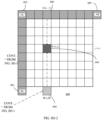
- the determined inter prediction mode is the first inter prediction mode used for a non-directional motion field (which may also be referred to as the planar mode used for inter prediction).
- predicting a motion vector of a current sub-block in the current picture block includes:
- the predicting or deriving first motion information of a right-side spatially-adjacent block, of the current picture block, in a same row as the current sub-block of the current picture block may be implemented in various manners, including the following manners.
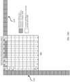
- the first motion information is obtained based on a linear interpolation of fifth motion information of a lower-right spatially-adjacent block of a first co-located block of the current picture block and sixth motion information of an upper-right spatially-adjacent block of the current picture block, where the first co-located block is a picture block that is in a reference picture and whose size, shape, and coordinates are the same as those of the current picture block.
- Motion information of a first right-side spatially-adjacent block of a first co-located block of the current picture block is determined as the first motion information, where a row in which the first right-side spatially-adjacent block is located in the first co-located block is the same as the row in which the current sub-block is located in the current picture block.
- Motion information of a second right-side spatially-adjacent block of a second co-located block of the current picture block is determined as the first motion information, where the second co-located block is a picture block that is in a reference picture and that has a specified location offset from the current picture block, a motion vector of a representative spatially-adjacent block of the current picture block is used to indicate the specified location offset, and a row in which the second right-side spatially-adjacent block is located in the second co-located block is the same as the row in which the current sub-block is located in the current picture block.
- Sixth motion information of an upper-right spatially-adjacent block of the current picture block is determined as the first motion information, or an average value of motion information of a plurality of upper-right spatially-adjacent blocks of the current picture block is determined as the first motion information.
- the foregoing four derivation manners may be used in combination based on specific logic. For example, if the first motion information cannot be derived in the first manner, the fourth manner is further used to derive the first motion information. For another example, the first manner, the second manner, the third manner, and the fourth manner are sequentially used for derivation to obtain the first motion information.
- the predicting or deriving second motion information of a lower spatially-adjacent block, of the current picture block, in a same column as the current sub-block of the current picture block may be implemented in various manners, including the following manners.
- the second motion information is obtained based on a linear interpolation of the fifth motion information of the lower-right spatially-adjacent block of the first co-located block of the current picture block and seventh motion information of a lower-left spatially-adjacent block of the current picture block, where the first co-located block is the picture block that is in the reference picture and whose size, shape, and coordinates are the same as those of the current picture block.
- Motion information of a first lower spatially-adjacent block of the first co-located block of the current picture block is determined as the second motion information, where the first co-located block is the picture block that is in the reference picture and whose size, shape, and coordinates are the same as those of the current picture block, and a column in which the first lower spatially-adjacent block is located in the first co-located block is the same as the column in which the current sub-block is located in the current picture block.
- Motion information of a second lower spatially-adjacent block of the second co-located block of the current picture block is determined as the second motion information, where the second co-located block is the picture block that is in the reference picture and that has the specified location offset from the current picture block, the motion vector of the representative spatially-adjacent block of the current picture block is used to indicate the specified location offset, and a column in which the second lower spatially-adjacent block is located in the second co-located block is the same as the column in which the current sub-block is located in the current picture block.
- Seventh motion information of a lower-left spatially-adjacent block of the current picture block is determined as the second motion information, or an average value of motion information of a plurality of lower-left spatially-adjacent blocks of the current picture block is determined as the second motion information.
- the foregoing four derivation manners may be used in combination based on specific logic. For example, if the second motion information cannot be derived in the first manner, the fourth manner is further used to derive the second motion information. For another example, the first manner, the second manner, the third manner, and the fourth manner are sequentially used for derivation to obtain the second motion information.
- the motion vector of the current sub-block is derived by using weighted values of horizontal and vertical linear interpolations, so that a motion vector of a picture block with a graded motion field or a sub-block of such a picture block can be better predicted, thereby improving motion vector prediction accuracy.
- the determined inter prediction mode is the second inter prediction mode used for a non-directional motion field (also referred to as the direct current coefficient DC mode used for inter prediction), and predicting motion information of a current sub-block in the current picture block includes:
- the motion vector of the current sub-block is derived by using an average value of motion vectors of the direct left-side spatially-adjacent block and the upper spatially-adjacent block of the current picture block, so that a motion vector of a picture block with a smooth motion field or a sub-block of such a picture block can be better predicted, thereby improving motion vector prediction accuracy.
- the determined inter prediction mode is an inter-frame direction prediction mode used for a directional motion field (also referred to as a direction prediction mode used for inter prediction), the predicting motion information of a current sub-block in the current picture block includes:
- reference blocks in the reference row are a row of upper spatially-adjacent blocks adjacent to the first row of sub-blocks of the current picture block
- reference blocks in the reference column are a column of left-side spatially-adjacent blocks adjacent to the first column of sub-blocks of the current picture block.
- motion vectors of one or more sub-blocks in a prediction direction are the same, and a value of the motion vector depends on a motion vector of a target reference block, so that a motion vector of a picture block with a directional motion field or a sub-block of such a picture block can be better predicted, thereby improving motion vector prediction accuracy.
- Motion information mentioned in the embodiments of this application mainly refers to a motion vector.
- the motion information may further include reference picture information, and the reference picture information may include but is not limited to a reference picture list and a reference picture index corresponding to the reference picture list.
- the method in the embodiments of this application may further include:
- the method in the embodiments of this application may further include: selectively filtering the motion information of the target reference block based on the prediction direction or angle corresponding to the inter-frame direction prediction mode.
- the method in the embodiments of this application may further include: filtering motion information of a boundary sub-block of the current picture block, where the boundary sub-block is one or more sub-blocks located at a boundary of the current picture block.
- motion information of a boundary sub-block of the current picture block in a specific inter prediction mode is filtered.
- the inter prediction method in the embodiments of this application may further include:
- the determining an inter prediction mode used to perform inter prediction on a current picture block includes: determining that the inter prediction mode indicated by the second identifier is the inter prediction mode used to perform inter prediction on the current picture block; or if the inter prediction data does not include a second identifier used to indicate the inter prediction mode of the current picture block, the determining an inter prediction mode used to perform inter prediction on a current picture block includes: determining that the first inter prediction mode used for a non-directional motion field (also referred to as the planar mode used for inter prediction) is the inter prediction mode used to perform inter prediction on the current picture block.
- the first inter prediction mode used for a non-directional motion field also referred to as the planar mode used for inter prediction
- the determining an inter prediction mode used to perform inter prediction on a current picture block includes: determining an inter prediction mode that is in the candidate inter prediction mode set and that has a smallest bit rate distortion cost for encoding the current picture block, as the inter prediction mode used to perform inter prediction on the current picture block. It should be understood that, if a first inter prediction mode used for a smooth or graded motion field (also referred to as a planar mode used for inter prediction) has the smallest bit rate distortion cost for encoding the current picture block, the first inter prediction mode used for a smooth or graded motion field is determined as the inter prediction mode used to perform inter prediction on the current picture block.
- the inter prediction method in the embodiments of this application may further include: encoding inter prediction data into a bitstream, where the inter prediction data includes a first identifier used to indicate whether to perform inter prediction on the current picture block by using the candidate inter prediction mode set, or the inter prediction data includes a first identifier used to indicate whether to perform inter prediction on the current picture block by using the candidate inter prediction mode set and a second identifier used to indicate the inter prediction mode of the current picture block.
- an embodiment of this application provides a video picture inter prediction apparatus, including functional units configured to implement any method in the first aspect.
- the video picture inter prediction apparatus may include:
- the inter prediction processing unit is specifically configured to:
- the video picture inter prediction apparatus is, for example, applied to a video coding apparatus (a video encoder) or a video decoding apparatus (a video decoder).
- an embodiment of this application provides a video encoder, where the video encoder is configured to encode a picture block, and includes:
- the entropy encoder is further configured to encode a second identifier into the bitstream, where the second identifier is used to indicate an inter prediction mode of the to-be-encoded picture block, in other words, the second identifier is used to indicate which new inter prediction mode is used to perform inter prediction on the to-be-encoded picture block.
- an embodiment of this application provides a video decoder, where the video decoder is configured to decode a bitstream to obtain a picture block, and includes:
- the entropy decoder is further configured to decode the bitstream to obtain a second identifier, where the second identifier is used to indicate the inter prediction mode of the to-be-decoded picture block, in other words, the second identifier is used to indicate which new inter prediction mode is used for the to-be-decoded picture block.
- an embodiment of this application provides a device for decoding video data, where the device includes:
- an embodiment of this application provides a device for encoding video data, where the device includes:
- an embodiment of this application provides a device for decoding video data, where the device includes:
- an embodiment of this application provides a motion information prediction method, where the method includes:
- an embodiment of this application provides an encoding device, including a non-volatile memory and a processor that are coupled to each other.
- the processor invokes program code stored in the memory, to perform some or all steps of any method in the first aspect.
- an embodiment of this application provides a decoding device, including a non-volatile memory and a processor that are coupled to each other.
- the processor invokes program code stored in the memory, to perform some or all steps of any method in the first aspect.
- an embodiment of this application provides a computer-readable storage medium.
- the computer-readable storage medium stores program code, and the program code includes an instruction used to perform some or all steps of any method in the first aspect.
- an embodiment of this application provides a computer program product.
- the computer program product runs on a computer, the computer is enabled to perform some or all steps of any method in the first aspect.
- an embodiment of this application provides a video picture inter prediction method, including: determining an inter prediction mode used to perform inter prediction on a current picture block, where the inter prediction mode is one mode in a candidate inter prediction mode set, and the candidate inter prediction mode set includes a first inter prediction mode used for a smooth or graded motion field; and predicting motion information of each sub-block in the current picture block based on the determined inter prediction mode, and performing inter prediction on the current picture block by using the motion information of each sub-block in the current picture block.
- an embodiment of this application provides a video picture inter prediction apparatus, including functional units configured to implement any method in the thirteenth aspect.
- the video picture inter prediction apparatus may include:
- temporal and spatial similarities in the video stream may be used to improve encoding performance.
- motion information used for the current picture block may be predicted based on a previously encoded block in the video stream, and a difference (also referred to as a residual) between a prediction block and the current picture block (that is, an original block) is identified, so as to encode the current picture block based on the previously encoded block.
- a difference also referred to as a residual
- a prediction block and the current picture block that is, an original block
- a motion vector is an important parameter in an inter prediction process, and represents a spatial displacement of the previously encoded block relative to the current to-be-encoded block.
- a motion estimation method such as motion search, may be used to obtain the motion vector.
- a bit representing a motion vector is included in an encoded bitstream, to allow a decoder to reproduce a prediction block, and to further obtain a reconstructed block.
- it is further proposed to differentially encode a motion vector by using a reference motion vector to be specific, to encode only a difference between the motion vector and the reference motion vector instead of encoding the entire motion vector.
- a reference motion vector may be selected from motion vectors previously used in a video stream. Selecting a previously used motion vector to encode a current motion vector can further reduce a quantity of bits included in an encoded video bitstream.
- This application is not limited to inter prediction modes in existing standards, for example, two inter prediction modes for a prediction unit (PU) in the HEVC standard: a merge mode (a skip mode is considered as a special case of the merge mode) and an AMVP mode.
- a merge mode a skip mode is considered as a special case of the merge mode
- AMVP mode an AMVP mode.
- this application further proposes a plurality of new inter prediction modes, including a plurality of inter prediction modes used for (predicting) a non-directional motion field and/or a plurality of inter prediction modes used for (predicting) a directional motion field, to form a candidate inter prediction mode set.
- the plurality of inter prediction modes used for (predicting) a non-directional motion field may include a first inter prediction mode used for a non-directional motion field (for example, a first inter prediction mode used for a smooth motion field and a graded motion field, a mode 0 for short) and a second inter prediction mode used for a non-directional motion field (for example, a second inter prediction mode mainly used for a smooth motion field, a mode 1 for short).
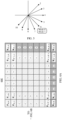
- the plurality of inter prediction modes used for (predicting) a directional motion field (inter-frame direction prediction modes for short) herein may correspond to different prediction directions or angles.
- a quantity of inter-frame direction prediction modes in this application is not limited to 9 (that is, modes 2 to 10 shown in Table 2) or 32 (that is, modes 2 to 33 shown in Table 3), and the quantity of inter-frame direction prediction modes may increase or decrease with a motion vector prediction precision requirement.
- the mode 0 may be understood as a planar mode used for inter prediction
- the mode 1 may be understood as a DC mode used for inter prediction
- the planar mode is applicable to a picture block whose motion field changes slowly or a sub-block of such a picture block.
- a DC mode used for intra prediction an average value of motion vectors of a left-side adjacent block and an upper adjacent block of a current picture block is used as a motion vector of the current picture block or a sub-block of the current picture block.
- the DC mode is applicable to a smooth picture block or a sub-block of a smooth picture block.
- the inter-frame direction prediction mode is applicable to a picture block with a directional motion field, to predict a motion vector of the picture block or a sub-block of the picture block.
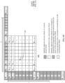
- angular parameters A of the inter-frame direction prediction modes (2 to 10) have the following correspondence: Table 2 Mode 2 3 4 5 6 7 8 9 10 A 32 15 0 -15 -32 -15 0 15 32
- angular parameters A of the inter-frame direction prediction modes (2 to 33) have the following correspondence: Table 3 Horizontal modes Mode 2 3 4 5 6 7 8 9 10 11 12 13 14 15 16 17 A 32 26 21 17 13 9 5 2 0 -2 -5 -9 -13 -17 -21 -26 Vertical modes Mode 18 19 20 21 22 23 24 25 26 27 28 29 30 31 32 33 A -32 -26 -21 -17 -13 -9 -5 -2 0 2 5 9 13 17 21 26
- a candidate inter prediction mode set including but not limited to the foregoing modes 0, 1, 2, ..., 10 is described.
- a video encoder determines or selects, from the candidate inter prediction mode set during video data sequence encoding, an inter prediction mode used to perform inter prediction on a current picture block (for example, the video encoder encodes video data by using a plurality of inter prediction modes and selects an inter prediction mode with intermediate bit rate distortion for encoding the picture block), performs inter prediction on the current picture block based on the determined inter prediction mode, and then completes encoding of the current picture block.
- the candidate inter prediction mode set including the foregoing modes 0, 1, 2, ..., 10 is used for description herein.
- the candidate inter prediction mode set in this application is not limited thereto.
- FIG. 1 is a block diagram of an example video coding and decoding system 1 according to an embodiment of this application.
- video codec generally refers to a video encoder and a video decoder.
- video coding/decoding or “encoding/decoding” may generally refer to video coding or video decoding.
- a video encoder 100 and a video decoder 200 in the video coding and decoding system 1 are configured to predict motion information, for example, a motion vector, of a current encoded/decoded picture block or a sub-block of a current encoded/decoded picture block according to various method examples described in any one of the plurality of new inter prediction modes proposed in this application, so that the predicted motion vector is maximally close to a motion vector obtained by using a motion estimation method. In this way, a motion vector difference does not need to be transmitted during encoding, thereby further improving encoding and decoding performance.
- motion information for example, a motion vector, of a current encoded/decoded picture block or a sub-block of a current encoded/decoded picture block according to various method examples described in any one of the plurality of new inter prediction modes proposed in this application, so that the predicted motion vector is maximally close to a motion vector obtained by using a motion estimation method. In this way, a motion vector difference does not need to be transmitted during en
- the video coding and decoding system 1 includes a source apparatus 10 and a destination apparatus 20.
- the source apparatus 10 generates encoded video data. Therefore, the source apparatus 10 may be referred to as a video coding apparatus.
- the destination apparatus 20 may decode the encoded video data generated by the source apparatus 10. Therefore, the destination apparatus 20 may be referred to as a video decoding apparatus.
- Various implementation solutions of the source apparatus 10, the destination apparatus 20, or both the source apparatus 10 and the destination apparatus 20 may include one or more processors and a memory coupled to the one or more processors.
- the memory may include but is not limited to a RAM, a ROM, an EEPROM, a flash memory, or any other medium that can be used to store desired program code in a form of an instruction or a data structure accessible to a computer, as described in this specification.
- the source apparatus 10 and the destination apparatus 20 may include various apparatuses, including a desktop computer, a mobile computing apparatus, a notebook (for example, laptop) computer, a tablet computer, a set-top box, a handheld telephone such as a "smart" phone, a television set, a camera, a display apparatus, a digital media player, a video game console, an in-vehicle computer, and similar apparatuses.
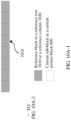
- the destination apparatus 20 may receive the encoded video data from the source apparatus 10 over a link 30.
- the link 30 may include one or more media or apparatuses that can move the encoded video data from the source apparatus 10 to the destination apparatus 20.
- the link 30 may include one or more communications media that enable the source apparatus 10 to directly transmit the encoded video data to the destination apparatus 20 in real time.
- the source apparatus 10 may modulate the encoded video data according to a communications standard (for example, a wireless communications protocol), and may transmit the modulated video data to the destination apparatus 20.
- the one or more communications media may include a wireless communications medium and/or a wired communications medium, for example, a radio frequency (RF) spectrum or one or more physical transmission lines.
- RF radio frequency
- the one or more communications media may form a part of a packet-based network, and the packet-based network is, for example, a local area network, a wide area network, or a global network (for example, the internet).
- the one or more communications media may include a router, a switch, a base station, or another device facilitating communication from the source apparatus 10 to the destination apparatus 20.
- the encoded data may be output to a storage apparatus 40 through an output interface 140.
- the encoded data may be accessed from the storage apparatus 40 through an input interface 240.
- the storage apparatus 40 may include any one of a plurality of distributed or locally accessed data storage media, for example, a hard disk drive, a Blu-ray disc, a DVD, a CD-ROM, a flash memory, a volatile or non-volatile memory, or any other suitable digital storage medium configured to store encoded video data.
- the storage apparatus 40 may correspond to a file server or another intermediate storage apparatus that can store encoded video data generated by the source apparatus 10.
- the destination apparatus 20 may access the stored video data from the storage apparatus 40 through streaming transmission or downloading.
- the file server may be any type of server that can store the encoded video data and transmit the encoded video data to the destination apparatus 20. Examples of the file server include a network server (for example, used for a website), an FTP server, a network-attached storage (NAS) apparatus, or a local disk drive.
- NAS network-attached storage
- the destination apparatus 20 may access the encoded video data through any standard data connection (including an internet connection), which may include a wireless channel (for example, a Wi-Fi connection), a wired connection (for example, a DSL or a cable modem), or a combination thereof that is suitable for accessing the encoded video data stored on the file server.
- Transmission of the encoded video data from the storage apparatus 40 may be streaming transmission, downloading transmission, or a combination thereof.
- a motion vector prediction technology in this application may be applied to video coding and decoding, to support a plurality of multimedia applications, for example, over-the-air television broadcast, cable television transmission, satellite television transmission, streaming video transmission (for example, over the internet), encoding of video data stored in a data storage medium, decoding of video data stored in a data storage medium, or other applications.
- the video coding and decoding system 1 may be configured to support unidirectional or bidirectional video transmission to support applications such as video streaming transmission, video playback, video broadcast, and/or videotelephony.
- the video coding and decoding system 1 described in FIG. 1 is merely an example, and the technology in this application may be applicable to a video coding/decoding setting (for example, video coding or video decoding) that does not necessarily include any data communication between an encoding apparatus and a decoding apparatus.
- data is retrieved from a local memory, is transmitted on a network in a streaming manner, and the like.
- the video coding apparatus may encode the data and store the data in the memory, and/or the video decoding apparatus may retrieve the data from the memory and decode the data.
- apparatuses that only encode data and store the data to the memory and/or retrieve the data from the memory and decode the data and that do not communicate with each other perform encoding and decoding.
- the source apparatus 10 includes a video source 120, the video encoder 100, and the output interface 140.
- the output interface 140 may include a modulator/demodulator (modem) and/or a transmitter.
- the video source 120 may include a video capture apparatus (for example, a camera), a video archive containing previously captured video data, a video feed-in interface for receiving video data from a video content provider, and/or a computer graphics system for generating video data, or a combination of these sources of video data.
- the video encoder 100 may encode video data that is from the video source 120.
- the source apparatus 10 directly transmits the encoded video data to the destination apparatus 20 through the output interface 140.
- the encoded video data may alternatively be stored on the storage apparatus 40, so that the destination apparatus 20 subsequently accesses the encoded video data for decoding and/or playing.
- the destination apparatus 20 includes the input interface 240, the video decoder 200, and a display apparatus 220.
- the input interface 240 includes a receiver and/or a modem.
- the input interface 240 may receive the encoded video data over the link 30 and/or from the storage apparatus 40.
- the display apparatus 220 may be integrated with the destination apparatus 20 or may be located outside the destination apparatus 20. Generally, the display apparatus 220 displays decoded video data.
- the display apparatus 220 may include a plurality of types of display apparatuses, for example, a liquid crystal display (LCD), a plasma display, an organic light-emitting diode (OLED) display, or another type of display apparatus.
- LCD liquid crystal display
- OLED organic light-emitting diode
- the video encoder 100 and the video decoder 200 may be respectively integrated with an audio encoder and an audio decoder, and may include a proper multiplexer-demultiplexer unit or other hardware and software, to process encoding of both audio and video in a common data stream or separate data streams.
- the MUX-DEMUX unit may comply with the ITU H.223 multiplexer protocol, or another protocol such as the user datagram protocol (UDP).
- the video encoder 100 and the video decoder 200 each may be implemented as, for example, any one of the following plurality of circuits: one or more microprocessors, a digital signal processor (DSP), an application-specific integrated circuit (ASIC), a field programmable gate array (FPGA), discrete logic, hardware, or any combination thereof.
- DSP digital signal processor
- ASIC application-specific integrated circuit
- FPGA field programmable gate array
- the apparatus may store, in a proper non-volatile computer-readable storage medium, an instruction used for the software, and may use one or more processors to execute the instruction in hardware, to implement the technology in this application. Any one of the foregoing content (including hardware, software, a combination of hardware and software, and the like) may be considered as one or more processors.
- the video encoder 100 and the video decoder 200 each may be included in one or more encoders or decoders, and either the encoder or the decoder may be integrated into a combined encoder/decoder (codec) in a corresponding apparatus to be a part of the combined encoder/decoder.
- codec combined encoder/decoder
- the video encoder 100 may be generally referred to as another apparatus "signaling” or “transmitting” some information to, for example, the video decoder 200.
- the term “signaling” or “transmitting” may roughly refer to transfer of a syntax element and/or other data used to decode compressed video data. The transfer may occur in real time or almost in real time. Alternatively, the communication may occur after a period of time, for example, may occur when a syntax element in an encoded bitstream is being stored into a computer-readable storage medium during encoding, and then the decoding apparatus may retrieve the syntax element at any time after the syntax element is stored in the medium.
- the video encoder 100 and the video decoder 200 may operate according to a video compression standard, such as HEVC, or an extension thereof, and may comply with an HEVC test model (HM).
- HEVC HEVC test model
- the video encoder 100 and the video decoder 200 may operate according to other industry standards, for example, ITU-T H.264 and H.265 standards, or extensions of such standards.
- ITU-T H.264 and H.265 standards or extensions of such standards.
- the technology in this application is not limited to any specific encoding and decoding standards.
- the video encoder 100 is configured to encode a syntax element related to a current to-be-encoded picture block into a digital video output bitstream (a bitstream or a code stream for short).
- the syntax element used for inter prediction of the current picture block is referred to as inter prediction data for short.
- the inter prediction data may include a first identifier used to indicate whether to perform inter prediction on the current picture block by using the candidate inter prediction mode set (in other words, a first identifier used to indicate whether to perform inter prediction on the current picture block by using the new inter prediction mode proposed in this application).
- the inter prediction data may include a first identifier used to indicate whether to perform inter prediction on the current to-be-encoded picture block by using the candidate inter prediction mode set and a second identifier used to indicate an inter prediction mode of the current to-be-encoded picture block.
- the video encoder 100 is further configured to: determine or select (S301), from the candidate inter prediction mode set, the inter prediction mode used to perform inter prediction on the current picture block (for example, select, from a plurality of new inter prediction modes, an inter prediction mode with an intermediate bit rate distortion cost or a smallest bit rate distortion cost for encoding the current picture block); and encode the current picture block based on the determined inter prediction mode (S303).
- An encoding process herein may include: predicting motion information of one or more sub-blocks (which may specifically be motion information of each sub-block or all sub-blocks) in the current picture block based on the determined inter prediction mode, and performing inter prediction on the current picture block by using the motion information of the one or more sub-blocks in the current picture block.
- the video encoder 100 only needs to encode the syntax element related to the current to-be-encoded picture block into the bitstream (also referred to as a code stream). Otherwise, in addition to the syntax element, the corresponding residual further needs to be encoded into the bitstream.
- the video decoder 200 is configured to: decode a bitstream to obtain a syntax element related to a current to-be-decoded picture block (S401), where the syntax element used for inter prediction of the current picture block is referred to as inter prediction data for short, and the inter prediction data includes a first identifier used to indicate whether to perform inter prediction on the current to-be-decoded picture block by using the candidate inter prediction mode set (that is, a first identifier used to indicate whether to perform inter prediction on the current to-be-decoded picture block by using the new inter prediction mode proposed in this application); when the inter prediction data instructs to predict the current picture block by using the candidate inter prediction mode set (that is, the new inter prediction mode), determine an inter prediction mode that is in the candidate inter prediction mode set and that is used to perform inter prediction on the current picture block (S403); and decode the current picture block based on the determined inter prediction mode (S405).
- the candidate inter prediction mode set that is, the new inter prediction mode
- a decoding process herein may include: predicting motion information of one or more sub-blocks in the current picture block based on the determined inter prediction mode, and performing inter prediction on the current picture block by using the motion information of the one or more sub-blocks in the current picture block.
- the video decoder 200 is configured to determine that the inter prediction mode indicated by the second identifier is the inter prediction mode used to perform inter prediction on the current picture block.
- the video decoder 200 is configured to determine that the first inter prediction mode used for a non-directional motion field is the inter prediction mode used to perform inter prediction on the current picture block.
- the candidate inter prediction mode set herein may be one mode, or may be a plurality of modes.
- the mode may be determined as the inter prediction mode used to encode or decode the current picture block.
- a mode with a highest priority or ranked top in the set may be determined by default as the inter prediction mode used to encode or decode the current picture block, or the mode indicated by the second identifier may be determined as the inter prediction mode used to decode the current picture block.
- the new inter prediction modes are classified, based on a motion field feature, into an inter prediction mode used for a non-directional motion field and/or an inter prediction mode used for a directional motion field.
- motion information for example, a motion vector
- the predicted motion vector of the current picture block is basically close to a motion vector obtained by using the motion estimation method. In this way, a motion vector difference does not need to be transmitted during encoding, and a bit rate is reduced with video quality unchanged. Therefore, encoding and decoding performance of the video coding and decoding system in this embodiment of this application is further improved.
- FIG. 2A is a block diagram of an example video encoder 100 according to an embodiment of this application.
- the video encoder 100 is configured to output a video to a post-processing entity 41.
- the post-processing entity 41 represents an instance of a video entity that can process encoded video data that is from the video encoder 100, for example, a media aware network element (MANE) or a splicing apparatus/an editing apparatus.
- the post-processing entity 41 may be an instance of a network entity.
- the post-processing entity 41 and the video encoder 100 may be parts of separate apparatuses, while in other cases, functionality described with respect to the post-processing entity 41 may be performed by a same apparatus including the video encoder 100.
- the post-processing entity 41 is an instance of the storage apparatus 40 in FIG. 1 .
- the video encoder 100 may encode a video picture block, for example, perform inter prediction on the video picture block, based on any new inter prediction mode in the candidate inter prediction mode set that includes the modes 0, 1, 2, ..., and 10 and that is proposed in this application.
- the video encoder 100 includes a prediction processing unit 108, a filter unit 106, a decoded picture buffer (DPB) 107, a summator 112, a transformer 101, a quantizer 102, and an entropy encoder 103.
- the prediction processing unit 108 includes an inter predictor 110 and an intra predictor 109.
- the video encoder 100 further includes an inverse quantizer 104, an inverse transformer 105, and a summator 111.
- the filter unit 106 represents one or more loop filters, for example, a deblocking filter, an adaptive loop filter (ALF), and a sample adaptive offset (SAO) filter.
- the filter unit 106 is shown as an intra-loop filter in FIG. 2A , in another implementation, the filter unit 106 may be implemented as a post-loop filter.
- the video encoder 100 may further include a video data memory and a partitioning unit (not shown in the figure).
- the video data memory may store video data that is to be encoded by a component of the video encoder 100.
- the video data stored in the video data memory may be obtained from a video source 120.
- the DPB 107 may be a reference picture memory that stores reference video data used for encoding the video data by the video encoder 100 in intra-frame and inter-frame coding/decoding modes.
- the video data memory and the DPB 107 each may be formed by any one of a plurality of memory apparatuses, for example, a dynamic random access memory (DRAM) including a synchronous DRAM (SDRAM), a magnetoresistive RAM (MRAM), a resistive RAM (RRAM), or another type of memory apparatus.
- the video data memory and the DPB 107 may be provided by a same memory apparatus or separate memory apparatuses.
- the video data memory may be disposed on a chip with other components of the video encoder 100, or may be outside the chip relative to those components.
- the video encoder 100 receives video data and stores the video data in the video data memory.
- the partitioning unit partitions the video data into picture blocks, and these picture blocks may further be partitioned into smaller blocks, for example, through picture block partitioning based on a quadtree structure or a binary-tree structure.
- the partitioning may further include partitioning into slices, tiles, or other larger units.
- the video encoder 100 usually includes a component for encoding a picture block in a to-be-encoded video slice.
- the slice may be divided into a plurality of picture blocks (and may be divided into picture block sets referred to as tiles).
- the prediction processing unit 108 may select one of a plurality of possible coding/decoding modes used for the current picture block, for example, one of a plurality of intra-frame coding/decoding modes or one of a plurality of inter-frame coding/decoding modes.
- the plurality of inter-frame coding/decoding modes include but are not limited to one or more of the modes 0, 1, 2, 3, ..., and 10 proposed in this application.
- the prediction processing unit 108 may provide obtained intra-coded/decoded and inter-coded/decoded blocks to the summator 112 to generate a residual block, and provide the blocks to the summator 111 to reconstruct an encoded block used as a reference picture.
- the intra predictor 109 in the prediction processing unit 108 may perform intra predictive coding on the current picture block relative to one or more neighboring blocks in a same frame or slice as the current to-be-encoded block, to remove spatial redundancy.
- the inter predictor 110 in the prediction processing unit 108 may perform inter predictive coding on the current picture block relative to one or more prediction blocks in one or more reference pictures, to remove temporal redundancy.
- the inter predictor 110 may be configured to determine an inter prediction mode used to encode the current picture block. For example, the inter predictor 110 may calculate rate-distortion values of various inter prediction modes in the candidate inter prediction mode set through rate-distortion analysis, and select an inter prediction mode with an optimal rate-distortion characteristic from the inter prediction modes.
- Rate-distortion analysis usually includes determining an amount of distortion (or error) between an encoded block and an original block that has not been encoded and that is to be encoded to generate the encoded block, and a bit rate (that is, a quantity of bits) used to generate the encoded block.
- the inter predictor 110 may determine an inter prediction mode that is in the candidate inter prediction mode set and that has a smallest bit rate distortion cost for encoding the current picture block, as the inter prediction mode used to perform inter prediction on the current picture block.
- the following describes in detail an inter predictive coding process, particularly a process of predicting motion information of one or more sub-blocks (which may specifically be each sub-block or all sub-blocks) in the current picture block in various inter prediction modes used for a non-directional or directional motion field in this application.
- the inter predictor 110 is configured to predict the motion information (for example, a motion vector) of the one or more sub-blocks in the current picture block based on the determined inter prediction mode, and obtain or generate a prediction block of the current picture block by using the motion information (for example, the motion vector) of the one or more sub-blocks in the current picture block.
- the inter predictor 110 may locate, in one reference picture in a reference picture list, the prediction block to which the motion vector points.
- the inter predictor 110 may further generate a syntax element associated with the picture block and a video slice, for use by a video decoder 200 when decoding the picture block of the video slice.
- the inter predictor 110 performs a motion compensation process by using motion information of each sub-block, to generate a prediction block of each sub-block, and further obtain a prediction block of the current picture block. It should be understood that the inter predictor 110 herein performs a motion estimation process and the motion compensation process.
- the inter predictor 110 may provide, to the entropy encoder 103, information indicating the selected inter prediction mode of the current picture block, so that the entropy encoder 103 encodes the information indicating the selected inter prediction mode.
- the video encoder 100 may include, in a transmitted bitstream, inter prediction data related to the current picture block.
- the inter prediction data may include a first identifier block_based_enable_flag, to indicate whether to perform inter prediction on the current picture block by using the new inter prediction mode proposed in this application.
- the inter prediction data may further include a second identifier block_based_index, to indicate which new inter prediction mode is used for the current picture block.
- a process of predicting the motion vector of the current picture block or the sub-block of the current picture block by using motion vectors of a plurality of reference blocks in the different modes 0, 1, 2, ..., and 10 is described in detail below.
- the intra predictor 109 may perform intra prediction on the current picture block. Specifically, the intra predictor 109 may determine an intra prediction mode used to encode the current block. For example, the intra predictor 109 may calculate rate-distortion values of various to-be-tested intra prediction modes through rate-distortion analysis, and select an intra prediction mode with an optimal rate-distortion characteristic from the to-be-tested modes. In any case, after selecting the intra prediction mode for the picture block, the intra predictor 109 may provide, to the entropy encoder 103, information indicating the selected intra prediction mode of the current picture block, so that the entropy encoder 103 encodes the information indicating the selected intra prediction mode.
- the video encoder 100 subtracts the prediction block from the current to-be-encoded picture block to form a residual picture block.
- the summator 112 represents one or more components that perform the subtraction operation.
- Residual video data in the residual block may be included in one or more TUs and applied to the transformer 101.
- the transformer 101 transforms the residual video data into a residual transform coefficient through transformation such as discrete cosine transform (DCT) or conceptually similar transform.
- DCT discrete cosine transform
- the transformer 101 may convert the residual video data from a pixel domain to a transform domain, for example, a frequency domain.
- the transformer 101 may send the obtained transform coefficient to the quantizer 102.
- the quantizer 102 quantizes the transform coefficient to further reduce a bit rate.
- the quantizer 102 may then scan a matrix including the quantized transform coefficient.
- the entropy encoder 103 may perform scanning.
- the entropy encoder 103 After quantization, the entropy encoder 103 performs entropy encoding on the quantized transform coefficient. For example, the entropy encoder 103 may perform context-adaptive variable-length coding (CAVLC), context-adaptive binary arithmetic coding (CABAC), syntax-based context-adaptive binary arithmetic coding (SBAC), probability interval partitioning entropy (PIPE) coding, or another entropy encoding method or technology.
- CAVLC context-adaptive variable-length coding
- CABAC context-adaptive binary arithmetic coding
- SBAC syntax-based context-adaptive binary arithmetic coding
- PIPE probability interval partitioning entropy
- the encoded bitstream may be transmitted to the video decoder 200, or archived for subsequent transmission or to be retrieved by the video decoder 200.
- the entropy encoder 103 may further perform entropy encoding on a syntax element
- the inverse quantizer 104 and the inverse transformer 105 respectively apply inverse quantization and inverse transformation, to reconstruct the residual block in the pixel domain, for example, for subsequent use as a reference block of a reference picture.
- the summator 111 adds the reconstructed residual block to the prediction block generated by the inter predictor 110 or the intra predictor 109, to generate a reconstructed picture block.
- the filter unit 106 may be applicable to the reconstructed picture block to reduce distortion such as blocking artifacts. Then, the reconstructed picture block is stored as the reference block in the decoded picture buffer 107, and may be used as the reference block by the inter predictor 110 to perform inter prediction on a block in a subsequent video frame or picture.
- the video encoder 100 may directly quantize a residual signal without processing by the transformer 101, and correspondingly, without processing by the inverse transformer 105.
- the video encoder 100 does not generate residual data, and correspondingly, processing by the transformer 101, the quantizer 102, the inverse quantizer 104, and the inverse transformer 105 is not required.
- the video encoder 100 may directly store the reconstructed picture block as the reference block without processing by the filter unit 106.
- the quantizer 102 and the inverse quantizer 104 in the video encoder 100 may be combined.
- FIG. 2B is a block diagram of an example video decoder 200 according to an embodiment of this application.
- the video decoder 200 includes an entropy decoder 203, a prediction processing unit 208, an inverse quantizer 204, an inverse transformer 205, a summator 211, a filter unit 206, and a decoded picture buffer 207.
- the prediction processing unit 208 may include an inter predictor 210 and an intra predictor 209.
- the video decoder 200 may perform a decoding process that is substantially inverse to the encoding process of the video encoder 100 in FIG. 2A .
- the video decoder 200 receives, from the video encoder 100, an encoded video bitstream representing a picture block of an encoded video slice and an associated syntax element.
- the video decoder 200 may receive video data from a network entity 42, and optionally may further store the video data in a video data memory (not shown in the figure).
- the video data memory may store video data that is to be decoded by a component of the video decoder 200, for example, the encoded video bitstream.
- the video data stored in the video data memory for example, may be obtained from a local video source such as a storage apparatus 40 or a camera, through wired or wireless network communication of the video data, or by accessing a physical data storage medium.
- the video data memory may be used as a coded picture buffer (CPB) configured to store the encoded video data that is from the encoded video bitstream. Therefore, although the video data memory is not shown in FIG. 2B , the video data memory and the DPB 207 may be a same memory, or may be separately disposed memories.
- the video data memory and the DPB 207 each may be formed by any one of a plurality of memory apparatuses, for example, a DRAM including a SDRAM, a MRAM, a RRAM, or another type of memory apparatus.
- the video data memory may be integrated into a chip with other components of the video decoder 200, or may be disposed outside the chip relative to those components.
- the network entity 42 may be, for example, a server, a MANE, a video editor/splicer, or another such apparatus configured to implement one or more of the technologies described above.
- the network entity 42 may or may not include a video encoder, for example, the video encoder 100.
- the network entity 42 may implement a part of the technology described in this application.
- the network entity 42 and the video decoder 200 may be parts of separate apparatuses, while in other cases, functionality described with respect to the network entity 42 may be performed by a same apparatus including the video decoder 200.
- the network entity 42 may be an instance of the storage apparatus 40 in FIG. 1 .
- the entropy decoder 203 of the video decoder 200 performs entropy decoding on the bitstream to generate a quantized coefficient and some syntax elements.
- the entropy decoder 203 forwards the syntax elements to the prediction processing unit 208.
- the video decoder 200 may receive a syntax element/syntax elements at a video slice level and/or a picture block level.
- the syntax element herein may include inter prediction data related to a current picture block.
- the inter prediction data may include a first identifier block_based_enable_flag, to indicate whether to perform inter prediction on the current picture block by using a candidate inter prediction mode set (in other words, to indicate whether to perform inter prediction on the current picture block by using a new inter prediction mode proposed in this application).
- the inter prediction data may further include a second identifier block_based_index, to indicate which new inter prediction mode is used for the current picture block.
- the intra predictor 209 of the prediction processing unit 208 may generate a prediction block of the picture block of the current video slice based on a signaled intra prediction mode and data of a previously decoded block that is from a current frame or picture.
- the inter predictor 210 of the prediction processing unit 208 may determine, based on the syntax element received from the entropy decoder 203, an inter prediction mode used to decode the current picture block of the current video slice, and decode (for example, perform inter prediction on) the current picture block based on the determined inter prediction mode.
- the inter predictor 210 may determine whether to predict the current picture block of the current video slice by using the new inter prediction mode, and if the syntax element instructs to predict the current picture block by using the new inter prediction mode, predict motion information of the current picture block of the current video slice or a sub-block of the current picture block based on the new inter prediction mode (for example, a new inter prediction mode specified by the syntax element or a default new inter prediction mode), to obtain or generate the prediction block of the current picture block or the sub-block of the current picture block by using the predicted motion information of the current picture block or the sub-block of the current picture block in a motion compensation process.
- the motion information herein may include reference picture information and a motion vector.
- the reference picture information may include but is not limited to unidirectional/bidirectional prediction information, a reference picture list number, and a reference picture index corresponding to a reference picture list.
- the prediction block may be generated from one of reference pictures in one of reference picture lists.
- the video decoder 200 may construct reference picture lists, namely, a list 0 and a list 1, based on reference pictures stored in the DPB 207.
- the reference frame index of the current picture may be included in one or more of the reference frame list 0 and the reference frame list 1.
- the video encoder 100 may signal to indicate whether to decode a specific syntax element of a specific block by using the new inter prediction mode, or may signal to indicate whether to use the new inter prediction mode and indicate which new inter prediction mode is specifically used to decode a specific syntax element of a specific block.
- the inter predictor 210 herein performs the motion compensation process. The following describes in detail an inter prediction process of predicting the motion information of the current picture block or the sub-block of the current picture block by using motion information of a reference block in various new inter prediction modes.
- the inverse quantizer 204 performs inverse quantization on, that is, dequantizes, a quantized transform coefficient provided in the bitstream and decoded by the entropy decoder 203.
- An inverse quantization process may include: determining a to-be-applied quantization degree by using a quantization parameter calculated by the video encoder 100 for each picture block in the video slice, and similarly determining a to-be-applied inverse quantization degree.
- the inverse transformer 205 applies inverse transform, for example, inverse DCT, inverse integer transform, or a conceptually similar inverse transform process, to the transform coefficient, so as to generate a pixel-domain residual block.
- the video decoder 200 After the inter predictor 210 generates the prediction block used for the current picture block or the sub-block of the current picture block, the video decoder 200 obtains a reconstructed block, that is, a decoded picture block, by summing the residual block that is from the inverse transformer 205 and the corresponding prediction block that is generated by the inter predictor 210.
- the summator 211 represents a component that performs the summation operation.
- a loop filter in a decoding loop or after a decoding loop
- the filter unit 206 may represent one or more loop filters, for example, a deblocking filter, an ALF, and a SAO filter.
- the filter unit 206 is shown as an intra-loop filter in FIG. 2B , in another implementation, the filter unit 206 may be implemented as a post-loop filter. In an example, the filter unit 206 is applicable to block reconstruction to reduce block distortion, and the result is output as a decoded video stream.
- a decoded picture block in a given frame or picture may further be stored in the decoded picture buffer 207, and the decoded picture buffer 207 stores a reference picture used for subsequent motion compensation.
- the decoded picture buffer 207 may be a part of a memory, and may further store a decoded video for subsequent presentation on a display apparatus (for example, the display apparatus 220 in FIG. 1 ), or may be separated from such a memory.
- the video decoder 200 may generate an output video stream without processing by the filter unit 206.
- the entropy decoder 203 of the video decoder 200 does not obtain a quantized coefficient through decoding, and correspondingly, processing by the inverse quantizer 204 and the inverse transformer 205 is not required.
- the following describes in detail a process of predicting motion information of a current picture block or a sub-block of a current picture block by using motion information of a plurality of reference blocks in various new inter prediction modes in this application.
- FIG. 6A and FIG. 6B are an example schematic diagram of motion information of a current picture block 600 and a reference block according to an embodiment of this application.
- W and H are a width and a height of the current picture block 600 and a co-located co-located block 600' of the current picture block 600.
- the reference block of the current picture block 600 includes an upper spatially-adjacent block and a left-side spatially-adjacent block of the current picture block 600, and a lower spatially-adjacent block and a right-side spatially-adjacent block of the co-located block 600'.
- the co-located block 600' is a picture block that is in a reference picture and whose size, shape, and coordinates are the same as those of the current picture block 600. It should be noted that there is no motion information of a lower spatially-adjacent block and a right-side spatially-adjacent block of the current picture block, which are not encoded yet. It should be understood that the current picture block 600 and the co-located block 600' may be of any block size. For example, the current picture block 600 and the co-located block 600' may include but are not limited to 16 ⁇ 16 pixels, 32 ⁇ 32 pixels, 32 ⁇ 16 pixels, 16 ⁇ 32 pixels, and the like. As described above, each picture frame may be partitioned into picture blocks for encoding.
- picture blocks may further be partitioned into smaller blocks.
- the current picture block 600 and the co-located block 600' may be partitioned into a plurality of M ⁇ N sub-blocks, that is, a size of each sub-block is M ⁇ N pixels.
- a size of each reference block is also M ⁇ N pixels, that is, the same as the size of the sub-block of the current picture block.
- the coordinates in FIG. 6A and FIG. 6B are measured by using an M ⁇ N block as a measurement unit.
- M ⁇ N and M multiplied by N may be used interchangeably to refer to a pixel size of a picture block in a horizontal dimension and a vertical dimension, to be specific, there are M pixels in a horizontal direction and N pixels in a vertical direction, where M and N represent nonnegative integer values.
- a block may not need to have a same quantity of pixels in the horizontal direction and in the vertical direction.
- the sub-block size of the current picture block and the reference block size may alternatively be 8 ⁇ 8 pixels, 8 ⁇ 4 pixels, 4 ⁇ 8 pixels, or a smallest prediction block size.
- the picture block described in this application may be understood as but is not limited to a prediction unit (PU), a coding unit (CU), a transform unit (TU), or the like.
- the CU may include one or more prediction units PU, or a size of the PU is the same as a size of the CU.
- the picture block may have a fixed or variable size, and the size may vary with different video compression coding/decoding standards.
- the current picture block is a current to-be-encoded or to-be-decoded picture block, for example, a to-be-encoded or to-be-decoded prediction unit.
- each left-side spatially-adjacent block of the current picture block 600 is available may be sequentially determined along a direction 1, and whether each upper spatially-adjacent block of the current picture block 600 is available may be sequentially determined along a direction 2.
- an adjacent block also referred to as a reference block, where "adjacent block” and “reference block” may be interchangeably used
- the adjacent block is available if the adjacent block exists and is inter-coded, or the adjacent block is unavailable if the adjacent block does not exist or is intra-coded.
- motion information of another adjacent reference block is copied as motion information of the adjacent block.
- the lower spatially-adjacent block and the right-side spatially-adjacent block of the co-located block 600' are available is detected by using a similar method. Details are not described herein.
- a size of an available reference block and the size of the sub-block of the current picture block are 4 ⁇ 4, motion information of the available reference block may be directly obtained or fetched. If a size of an available reference block is, for example, 8 ⁇ 4 or 8 ⁇ 8, motion information of a center 4 ⁇ 4 block of the available reference block may be obtained as motion information of the available reference block. Coordinates of an upper-left vertex of the center 4 ⁇ 4 block relative to an upper-left vertex of the reference block are ((W/4)/2 ⁇ 4, (H/4)/2 ⁇ 4).
- the division operation herein is an exact-division operation.
- the coordinates of the upper-left vertex of the center 4 ⁇ 4 block relative to the upper-left vertex of the reference block are (4, 0).
- motion information of an upper-left 4 ⁇ 4 block of the reference block may be obtained as the motion information of the available reference block.
- this application is not limited thereto.
- the following uses a sub-block to represent an M ⁇ N sub-block and uses an adjacent block to represent an adjacent M ⁇ N block for description.
- FIG. 7 is a flowchart of a process 700 of predicting motion information of a current sub-block in a current picture block based on a first inter prediction mode according to an embodiment of this application.
- the process 700 may be performed by the video encoder 100 or the video decoder 200, and specifically, may be performed by the inter predictor 110 of the video encoder 100 or the inter predictor 210 of the video decoder 200.
- the process 700 is described as a series of steps or operations. It should be understood that steps or operations of the process 700 may be performed in various sequences and/or simultaneously, not limited to an execution sequence shown in FIG. 7 .
- a video encoder or a video decoder is used for a video data stream with a plurality of video frames, to perform the process 700 including the following steps to predict motion information of a current sub-block of a current picture block of a current video frame.
- Step 701 Predict (derive), by using motion information of a plurality of reference blocks, first motion information of a right-side spatially-adjacent block 806, of the current picture block 600, in a same row as the current sub-block 604 of the current picture block 600 and second motion information of a lower spatially-adjacent block 808, of the current picture block 600, in a same column as the current sub-block 604 of the current picture block 600, where the reference blocks may include a picture block spatially and/or temporally adjacent to the current picture block 600 .
- the current picture block is a current to-be-encoded or to-be-decoded picture block.
- Step 703 Obtain a first predicted value P h (x, y) of the motion information of the current sub-block 604 based on a linear (horizontal) interpolation of the derived first motion information of the right-side spatially-adjacent block 806 and third motion information of a left-side adjacent block 802, of the current picture block 600, in the same row as the current sub-block 604.
- a weighted value of the first motion information of the right-side adjacent block 806, of the current picture block 600, in the same row as the current sub-block 604 and the third motion information of the left-side adjacent block 802, of the current picture block 600, in the same row as the current sub-block 604 is determined as the first predicted value P h (x, y) of the motion information of the current sub-block 604.
- a ratio of a weighting factor of the third motion information to a weighting factor of the first motion information is determined based on a ratio of a first distance between the right-side spatially-adjacent block 806, of the current picture block 600, in the same row as the current sub-block 604 of the current picture block 600 and the current sub-block 604 to a second distance between the current sub-block 604 and the left-side spatially-adjacent block 802, of the current picture block 600, in the same row as the current sub-block 604.
- Step 705 Obtain a second predicted value P v (x, y) of the motion information of the current sub-block 604 based on a linear (vertical) interpolation of the derived second motion information of the lower spatially-adjacent block 808 and fourth motion information of an upper adjacent block 809, of the current picture block 600, in the same column as the current sub-block 604.
- a weighted value of the fourth motion information of the upper spatially-adjacent block 809, of the current picture block 600, in the same column as the current sub-block 604 and the second motion information of the lower spatially-adjacent block 808, of the current picture block 600, in the same column as the current sub-block 604 is determined as the second predicted value P v (x, y) of the motion information of the current sub-block 604.
- a ratio of a weighting factor of the fourth motion information to a weighting factor of the second motion information is determined based on a ratio of a third distance between the lower spatially-adjacent block 808, of the current picture block 600, in the same column as the current sub-block 604 of the current picture block 600 and the current sub-block 604 to a fourth distance between the current sub-block 604 and the upper spatially-adjacent block 809, of the current picture block 600, in the same column as the current sub-block 604.
- Step 707 Determine the motion information P(x, y) of the current sub-block 604 by using the first predicted value P h (x, y) of the motion information of the current sub-block 604 and the second predicted value P v (x, y) of the motion information of the current sub-block 604.
- the motion information P(x, y) of the current sub-block 604 is obtained by performing weighting processing on the first predicted value P h (x, y) of the motion information of the current sub-block 604 and the second predicted value P v (x, y) of the motion information of the current sub-block 604. It should be understood that, when weighting factors are the same, the weighting processing is equivalent to calculating an average value, to be specific, an average value of the first predicted value P h (x, y) of the motion information of the current sub-block 604 and the second predicted value of the motion information of the current sub-block 604 is determined as the motion information of the current sub-block 604.
- step 701 may include the following steps: Step 701A-1: Obtain the first motion information of the right-side spatially-adjacent block 806, of the current picture block 600, in the same row as the current sub-block 604 of the current picture block 600 based on a linear (vertical) interpolation of fifth motion information of a lower-right spatially-adjacent block 807 of a first co-located block 600' (lower-right temporally-adjacent block for short) of the current picture block 600 and sixth motion information of an upper-right spatially-adjacent block 805 of the current picture block 600.
- Step 701A-2 Obtain the second motion information of the lower spatially-adjacent block 808, of the current picture block 600, in the same column as the current sub-block 604 of the current picture block 600 based on a linear interpolation (namely, a horizontal interpolation) of the fifth motion information of the lower-right spatially-adjacent block 807 of the first co-located block 600' (lower-right temporally-adjacent block for short) of the current picture block 600 and seventh motion information of a lower-left spatially-adjacent block 801 of the current picture block 600, where the first co-located block 600' is a picture block that is in a reference picture and whose size, shape, and coordinates are the same as those of the current picture block 600.
- a linear interpolation namely, a horizontal interpolation
- the first motion information of the right-side spatially-adjacent block 806 is obtained by performing the vertical interpolation on the fifth motion information of the lower-right spatially-adjacent block 807 of the first co-located block 600' and the sixth motion information of the upper-right spatially-adjacent block 805 of the current picture block 600 according to formula (1).
- step 701A-2 the second motion information of the lower spatially-adjacent block 808 is obtained by performing the horizontal interpolation on the fifth motion information of the lower-right spatially-adjacent block 807 of the first co-located block 600' and the seventh motion information of the lower-left spatially-adjacent block 801 of the current picture block 600 according to formula (2).
- R W , y H ⁇ y ⁇ 1 ⁇ AR + y + 1 ⁇ BR / H B x
- H W ⁇ x ⁇ 1 ⁇ BL + x + 1 ⁇ BR / W
- (x, y) represents coordinates of the current sub-block 604 relative to an upper-left sub-block of the current picture block 600
- x is an integer between 0 and W-1
- y is an integer between 0 and H-1
- W and H represent a width and a height (measured in sub-blocks) of the current picture block 600
- AR represents the sixth motion information of the upper-right spatially-adjacent block 805
- BR represents the fifth motion information of the lower-right temporally-adjacent block 807
- BL represents the seventh motion information of the lower-left spatially-adjacent block 801.
- the first predicted value of the motion information of the current sub-block 604 is obtained by performing the horizontal interpolation on the first motion information of the right-side spatially-adjacent block 806 and the third motion information of the left-side spatially-adjacent block 802 according to formula (3).
- step 705 the second predicted value of the motion information of the current sub-block 604 is obtained by performing the vertical interpolation on the second motion information of the lower spatially-adjacent block 808 and the fourth motion information of the upper spatially-adjacent block 809 according to formula (4).
- an average value of motion vectors obtained through the horizontal and vertical linear interpolations is a motion vector of the current sub-block.
- L (-1, y ) represents a third motion vector of the left-side spatially-adjacent block 802 in the row in which the current sub-block 604 is located
- R ( W, y ) represents a first motion vector of the right-side spatially-adjacent block 806 in the row in which the current sub-block 604 is located
- a ( x ,-1) represents a fourth motion vector of the upper spatially-adjacent block 809 in the column in which the current sub-block 604 is located
- B ( x, H ) represents a second motion vector of the lower spatially-adjacent block 808 in the column in which the current sub-block 604 is located
- P h ( x, y ) represents a motion vector obtained through the horizontal interpolation (that is, the first predicted value)
- P v ( x, y ) represents a motion vector obtained through the vertical interpolation (that is, the second predicted value)
- P(x, y) represents the motion
- step 701 may include the following steps: Step 701B-1: Determine sixth motion information of an upper-right spatially-adjacent block 805 of the current picture block 600 as the first motion information of the right-side spatially-adjacent block 806 in the same row as the current sub-block 604, or determine an average value of motion information of a plurality of upper-right spatially-adjacent blocks of the current picture block 600 as the first motion information of the right-side spatially-adjacent block 806.
- Step 701B-2 Determine seventh motion information of a lower-left spatially-adjacent block 801 of the current picture block 600 as the second motion information of the lower spatially-adjacent block 808 in the same column as the current sub-block 604, or determine an average value of motion information of a plurality of lower-left spatially-adjacent blocks of the current picture block 600 as the second motion information of the lower spatially-adjacent block 808.
- step 701 may include the following steps: Step 701C-1: Determine motion information of a first right-side spatially-adjacent block of a first co-located block 600' (right-side temporally-adjacent reference block for short) of the current picture block 600 as the first motion information of the right-side spatially-adjacent block 806, where a row in which the first right-side spatially-adjacent block is located in the first co-located block 600' is the same as the row in which the current sub-block 604 is located in the current picture block 600.
- Step 701C-2 Determine motion information of a first lower spatially-adjacent block of the first co-located block 600' (lower temporally-adjacent reference block for short) of the current picture block 600 as the second motion information of the lower spatially-adjacent block 808, where a column in which the first lower spatially-adjacent block is located in the first co-located block 600' is the same as the column in which the current sub-block 604 is located in the current picture block 600, and the first co-located block 600' is a picture block that is in a reference picture and whose size, shape, and coordinates are the same as those of the current picture block 600.
- step 701 may include the following steps: Step 701D-1: Determine motion information of a second right-side spatially-adjacent block of a second co-located block (right-side temporally-adjacent reference block for short) of the current picture block 600 as the first motion information of the right-side spatially-adjacent block 806, where the second co-located block is a picture block that is in a reference picture and that has a specified location offset from the current picture block 600, a motion vector of a representative spatially-adjacent block of the current picture block 600 is used to indicate the specified location offset, and a row in which the second right-side spatially-adjacent block is located
- Step 701D-2 Determine motion information of a second lower spatially-adjacent block of the second co-located block (lower temporally-adjacent reference block for short) of the current picture block 600 as the second motion information of the lower spatially-adjacent block 808, where the second co-located block is the picture block that is in the reference picture and that has the specified location offset from the current picture block 600, the motion vector of the representative spatially-adjacent block of the current picture block 600 is used to indicate the specified location offset, and a column in which the second lower spatially-adjacent block is located in the second co-located block is the same as the column in which the current sub-block 604 is located in the current picture block 600.
- the representative spatially-adjacent block herein may be an available spatially-adjacent block in left-side spatially-adjacent blocks or upper spatially-adjacent blocks shown in FIG. 6A and FIG. 6B , for example, may be the first available left-side spatially-adjacent block detected in a direction 1, or may be the first available upper spatially-adjacent block detected in a direction 2.
- the representative spatially-adjacent block may be the first available spatially-adjacent block obtained by sequentially detecting a plurality of specified spatially-adjacent location points of the current picture block in a merge mode, such as L ⁇ A ⁇ AR ⁇ BL ⁇ AL shown in FIG. 8A-1 and FIG.
- the representative spatially-adjacent block may alternatively be a representative spatially-adjacent block that is selected randomly or according to a predetermined rule from a plurality of available spatially-adjacent blocks obtained through sequential detection. This is not limited in this embodiment of this application.
- the current sub-block 604 in the current picture block 600 is used as a representative to describe a motion vector prediction process of the current sub-block 604.
- a motion vector prediction process of each sub-block in the current picture block 600 refer to the descriptions in this embodiment, and details are not described herein.
- the motion vector of the current sub-block is derived by using an average value of horizontal and vertical linear interpolations, so that a motion vector of a picture block with a graded motion field or a sub-block of such a picture block can be better predicted, thereby improving motion vector prediction accuracy.
- FIG. 9 is a schematic diagram of predicting motion information of a current sub-block in a current picture block based on a second inter prediction mode according to another embodiment of this application.
- an average value of third motion information of a left-side spatially-adjacent block 802, of the current picture block 600, in a same row as the current sub-block 604 of the current picture block 600 and fourth motion information of an upper spatially-adjacent block 809, of the current picture block 600, in a same column as the current sub-block 604 is determined as the motion information of the current sub-block 604.
- an average value of motion information of a plurality of left-side spatially-adjacent blocks of the current picture block 600 and motion information of a plurality of upper spatially-adjacent blocks of the current picture block 600 is determined as motion information of one or more sub-blocks (which may specifically be all sub-blocks) of the current picture block 600.
- the current sub-block 604 in the current picture block 600 is used as a representative to describe a motion vector prediction process of the current sub-block 604.
- a motion vector prediction process of each sub-block in the current picture block 600 refer to the descriptions in this embodiment, and details are not described herein.
- a motion vector of the current sub-block is derived by using an average value of motion vectors of a direct left-side spatially-adjacent block and the upper spatially-adjacent block of the current picture block, so that a motion vector of a picture block with a smooth motion field or a sub-block of such a picture block can be better predicted, thereby improving motion vector prediction accuracy.
- FIG. 10A-1 to FIG. 10E are schematic principle diagrams of predicting motion information of a current sub-block in a current picture block based on an inter-frame direction prediction mode according to another embodiment of this application.
- a process in which the video encoder 100 or the video decoder 200 (specifically the inter predictor 110 or the inter predictor 210) predicts the motion information of the current sub-block of the current picture block is as follows: A plurality of sub-blocks in the current picture block are projected to a reference row 1010 or a reference column 1020 based on a prediction direction corresponding to the inter-frame direction prediction mode.
- the reference row 1010 does not belong to the current picture block 600, and the reference row 1010 is a row of upper spatially-adjacent blocks adjacent to the first row of sub-blocks of the current picture block.
- the first column of the reference row 1010 may be aligned with the first column of the current picture block, or may not be aligned with the first column of the current picture block (for example, exceeding the first column of the current picture block and extending leftward).
- the reference column 1020 does not belong to the current picture block 600, and the reference column 1020 is a column of left-side spatially-adjacent adjacent to the first column of sub-blocks of the current picture block.
- the first row of the reference column 1020 may be aligned with the first row of the current picture block, and the last row of the reference column 1020 may be aligned with the last row of the current picture block, or may not be aligned with the last row of the current picture block 600 (for example, exceeding the last row of the current picture block and extending downward).
- a reference block on which the reference row 1010 intersects the reference column 1020 is an upper-left spatially-adjacent block of the current picture block 600. It should be understood that the projection herein is not limited to an operation, but is a description manner introduced to facilitate description of a correspondence between a sub-block and a target reference block.
- motion information of the target reference block is determined as the motion information of the current sub-block.
- weighting processing is performed on motion information of the two target reference blocks to obtain the motion information of the current sub-block, or weighting processing is performed on motion information of the two target reference blocks and left-side and right-side or upper and lower adjacent blocks of the two target reference blocks to obtain the motion information of the current sub-block.
- the former is weighting of two motion vectors
- the latter is weighting of four motion vectors.
- a weighting factor herein is determined based on a distance between a reference block and a projection point, and a shorter distance indicates a larger weight.
- the target reference block (also referred to as a projection reference block) mentioned herein is a reference block that is determined in the reference row 1010 or the reference column 1020 based on the prediction direction (angle) corresponding to the inter-frame direction prediction mode and that corresponds to the current sub-block. Such a correspondence may be understood as that the current sub-block and the target reference block are in a same prediction direction.
- FIG. 10A-1 and FIG. 10A-2 show a projection manner of an inter-frame direction prediction mode (the mode 2 in FIG. 5 or Table 2).
- a dashed-line arrow represents a prediction direction corresponding to the inter-frame direction prediction mode 2.
- the rest may be deduced by analogy, and is not described one by one herein.
- FIG. 10B-1 and FIG. 10B-2 show a projection manner of another inter-frame direction prediction mode (the mode 6 in FIG. 5 or Table 2).
- a dashed-line arrow represents a prediction direction corresponding to the inter-frame direction prediction mode 6.
- motion vectors of some reference blocks that is, some left-side adjacent reference blocks
- the reference column 1020 are projected or mapped as motion vectors of some corresponding reference blocks in the reference row (especially an extension part of the reference row).
- FIG. 10C shows a projection manner of another inter-frame direction prediction mode (a directly horizontal mode, for example, the mode 4 in FIG. 5 or Table 2, or the mode 10 in Table 3).
- a dashed-line arrow represents a prediction direction corresponding to the inter-frame direction prediction mode (that is, a horizontal direction).
- the rest may be deduced by analogy, and is not described one by one herein.
- FIG. 10D shows a projection manner of another inter-frame direction prediction mode (a directly vertical mode, for example, the mode 8 in FIG. 5 or Table 2, or the mode 26 in Table 3).
- a dashed-line arrow represents a prediction direction corresponding to the inter-frame direction prediction mode (that is, a vertical direction).
- the rest may be deduced by analogy, and is not described one by one herein.
- FIG. 10E shows a projection manner of still another inter-frame direction prediction mode (the mode 23 in Table 3).
- a bold arrow represents a prediction direction corresponding to the inter-frame direction prediction mode 23.
- a weighted value of motion vectors of two upper spatially-adjacent blocks 809 and 810 that are adjacent to each other is a motion vector of the current sub-block 604.
- motion vectors of some left-side adjacent reference blocks are projected to extend a reference row.
- a motion vector of a left-side spatially-adjacent block 802 is projected or mapped as a motion vector of an upper-left spatially-adjacent block 811 in an extension part of the reference row.
- i is an integer part of a projection displacement
- f represents a fractional part of the projection displacement
- A is an angular parameter
- y is a vertical coordinate of the current sub-block
- x is a horizontal coordinate of the current sub-block.
- (x, y) represents coordinates of the current sub-block relative to an upper-left sub-block of the current picture block.
- R(x+i-1, -1), R(x+i, -1), R(x+i+1, -1), and R(x+i+2, -1) represent motion vectors of four neighboring reference blocks.
- w[0], w[1], w[2], and w[3] represent weighting factors of the foregoing four reference blocks.
- P(x, y) represents a motion vector of the current subblock.
- 2-tap intra-frame interpolation filtering in HEVC may be used.
- (x, y) represents coordinates of the current sub-block relative to an upper-left sub-block of the current picture block.
- R(x+i, -1) and R(x+i+1, -1) represent motion vectors of two target reference blocks that neighbor each other.
- (32-f) and f represent weighting factors of the two target reference blocks.
- P(x, y) represents a motion vector of the current sub-block.
- motion vectors of one or more sub-blocks in a prediction direction are the same, and a value of the motion vector depends on a motion vector of a target reference block, so that a motion vector of a picture block with a directional motion field or a sub-block of such a picture block can be better predicted, thereby improving motion vector prediction accuracy.
- motion information of each reference block may include a motion vector, a reference picture list, and a reference picture index corresponding to the reference picture list.
- a reference picture index is used to identify a reference picture to which a motion vector in a specified reference picture list (RefPicList0 or RefPicList1) points.
- a motion vector (MV) refers to location offsets in a horizontal direction and a vertical direction, that is, a horizontal component of the motion vector and a vertical component of the motion vector.
- the video encoder 100 or the video decoder 200 may further be configured to (or the method in the embodiments of this application may further include):
- the motion vector is proportionally scaled based on a time distance between a current picture and a reference picture that is indicated by the reference picture index in the current motion information and a time distance between the current picture and a reference picture that is indicated by the target reference picture index.
- reference picture indexes that are respectively included in motion information of the plurality of reference blocks and that correspond to the list 0 are different, for example, a reference picture index, of a first reference block, corresponding to the list 0 is 0, and a reference picture index, of a second reference block, corresponding to the list 0 is 1, and when it is assumed that a reference picture index, of the current picture block, corresponding to the list 0 is 0, time-domain-distance-based scaling is performed on a motion vector (corresponding to the list 0) of the second reference block, to obtain a motion vector that points to a reference frame indicated by the reference picture index 0.
- the video encoder 100 or the video decoder 200 may further be configured to (or the method in the embodiments of this application may further include): selectively filter the motion information of the target reference block based on a prediction direction or angle corresponding to the inter-frame direction prediction mode.
- the motion vector of the target reference block is filtered before the motion vector of the current sub-block is derived by using the motion vector of the target reference block.
- motion information of an adjacent reference block may be used to filter the motion information of the target reference block by using a filter of ⁇ 1/4, 2/4, 1/4 ⁇ , where the adjacent reference block is an adjacent reference block that is directly adjacent to the target reference block (for example, is adjacent to the target reference block on a left or right side, or is adjacent to the target reference block on top or bottom).
- the motion information of the target reference block may be selectively filtered based on a block size and the prediction direction or angle corresponding to the inter-frame direction prediction mode. For example, a larger block and an inter-frame direction prediction mode with a larger angle indicates greater necessity of performing filtering processing in advance before the motion vector of the current sub-block is derived by using the motion vector of the target reference block.
- the video encoder 100 or the video decoder 200 may further be configured to (or the method in the embodiments of this application may further include): filter motion information of a boundary sub-block of the current picture block, where the boundary sub-block is one or more sub-blocks located at the boundary of the current picture block.
- motion information of the boundary sub-block of the current picture block in a specific inter prediction mode for example, the second inter prediction mode, a vertical prediction mode, or a horizontal prediction mode
- filtering may be performed by using a filter of ⁇ 1/4, 3/4 ⁇ or ⁇ 1/4, 2/4, 1/4 ⁇ , so that a motion vector of the boundary sub-block changes more smoothly. It should be understood that this application is not limited thereto.
- FIG. 11 is a schematic block diagram of an inter prediction apparatus 1100 according to an embodiment of this application. It should be noted that the inter prediction apparatus 1100 is not only applicable to inter prediction for decoding a video picture, but also applicable to inter prediction for encoding a video picture. It should be understood that the inter prediction apparatus 1100 herein may correspond to the inter predictor 110 in FIG. 2A , or may correspond to the inter predictor 210 in FIG. 2B .
- the inter prediction apparatus 1100 may include:
- the inter prediction processing unit 1102 is specifically configured to predict motion information of one or more sub-blocks (which may specifically be each sub-block or all sub-blocks) in the current picture block based on the determined inter prediction mode, and perform inter prediction on the current picture block by using the motion information of the one or more sub-blocks in the current picture block. It should be understood that, after a motion vector of the one or more sub-blocks in the current picture block is obtained through prediction, a prediction block of the corresponding sub-block may be generated through a motion compensation process, to obtain a prediction block of the current picture block.
- the inter prediction apparatus in this embodiment of this application can predict the motion information (for example, the motion vector) of the one or more sub-blocks in the current picture block based on any one of the inter prediction modes used for a directional motion field or a non-directional motion field.
- the predicted motion vector of the current picture block is basically close to a motion vector obtained by using a motion estimation method. Therefore, a motion vector difference MVD does not need to be transmitted during encoding, so that a bit rate is reduced with video quality unchanged. Therefore, encoding and decoding performance of the inter prediction apparatus in this embodiment of this application is further improved.
- the inter prediction processing unit 1102 is specifically configured to:
- the inter prediction processing unit 1102 is specifically configured to:
- the inter prediction processing unit 1102 is specifically configured to:
- the inter prediction processing unit 1102 is specifically configured to: determine, as the first predicted value of the motion information of the current sub-block, a weighted value of the first motion information of the right-side adjacent block, of the current picture block, in the same row as the current sub-block and the third motion information of the left-side adjacent block, of the current picture block, in the same row as the current sub-block, where a ratio of a weighting factor of the third motion information to a weighting factor of the first motion information is determined based on a ratio of a first distance between the right-side spatially-adjacent block, of the current picture block, in the same row as the current sub-block of the current picture block and the current sub-block to a second distance between the current sub-
- the inter prediction processing unit 1102 is specifically configured to: determine, as the second predicted value of the motion information of the current sub-block, a weighted value of the fourth motion information of the upper spatially-adjacent block, of the current picture block, in the same column as the current sub-block and the second motion information of the lower spatially-adjacent block, of the current picture block, in the same column as the current sub-block, where a ratio of a weighting factor of the fourth motion information to a weighting factor of the second motion information is determined based on a ratio of a third distance between the lower spatially-adjacent block, of the current picture block, in the same column as the current sub-block of the current picture block and the current sub-block to a fourth distance between the current sub-block and
- a motion vector of the current sub-block is derived by using an average value of horizontal and vertical linear interpolations, so that a motion vector of a picture block with a graded motion field or a sub-block of such a picture block can be better predicted, thereby improving motion vector prediction accuracy.
- the inter prediction processing unit 1102 is specifically configured to:
- a motion vector of the current sub-block is derived by using an average value of motion vectors of the direct left-side spatially-adjacent block and the upper spatially-adjacent block of the current picture block, so that a motion vector of a picture block with a smooth motion field or a sub-block of such a picture block can be better predicted, thereby improving motion vector prediction accuracy.
- the inter prediction processing unit 1102 is specifically configured to:
- motion vectors of one or more sub-blocks in a prediction direction are the same, and a value of the motion vector depends on a motion vector of a target reference block, so that a motion vector of a picture block with a directional motion field or a sub-block of such a picture block can be better predicted, thereby improving motion vector prediction accuracy.
- the inter prediction processing unit 1102 is further configured to:
- the apparatus 1100 may further include: an inter prediction data obtaining unit (not shown in the figure), configured to receive inter prediction data that includes a first identifier used to indicate whether to perform inter prediction on the current picture block by using the candidate inter prediction mode set.
- an inter prediction data obtaining unit (not shown in the figure), configured to receive inter prediction data that includes a first identifier used to indicate whether to perform inter prediction on the current picture block by using the candidate inter prediction mode set.
- the inter prediction mode determining unit 1101 is specifically configured to: when the inter prediction data instructs to predict the current picture block by using the candidate inter prediction mode set, determine, from the candidate inter prediction mode set, the inter prediction mode used to perform inter prediction on the current picture block.
- the inter prediction mode determining unit 1101 is specifically configured to determine that the inter prediction mode indicated by the second identifier is the inter prediction mode used to perform inter prediction on the current picture block.
- the inter prediction mode determining unit 1101 is specifically configured to determine that the first inter prediction mode used for a non-directional motion field (also referred to as the planar mode used for inter prediction) is the inter prediction mode used to perform inter prediction on the current picture block.
- the apparatus 1100 may further include: the inter prediction mode determining unit 1101 is specifically configured to: determine an inter prediction mode that is in the candidate inter prediction mode set and that has a smallest bit rate distortion cost for encoding the current picture block, as the inter prediction mode used to perform inter prediction on the current picture block.
- modules in the inter prediction apparatus in this embodiment of this application are functional entities for implementing various execution steps included in the inter prediction method in this application, to be specific, functional entities that can implement all steps in the inter prediction method in this application and extensions and variants of these steps.
- modules in the inter prediction apparatus in this embodiment of this application are functional entities for implementing various execution steps included in the inter prediction method in this application, to be specific, functional entities that can implement all steps in the inter prediction method in this application and extensions and variants of these steps.
- modules in the inter prediction apparatus in this embodiment of this application are functional entities for implementing various execution steps included in the inter prediction method in this application, to be specific, functional entities that can implement all steps in the inter prediction method in this application and extensions and variants of these steps.
- FIG. 12 is a schematic block diagram of an implementation of an encoding device or a decoding device (encoding/decoding device 1200 for short) according to an embodiment of this application.
- the encoding/decoding device 1200 may include a processor 1210, a memory 1230, and a bus system 1250.
- the processor and the memory are connected to each other by using the bus system.
- the memory is configured to store an instruction.
- the processor is configured to execute the instruction stored in the memory.
- the memory of the encoding/decoding device stores program code.
- the processor may invoke the program code stored in the memory, to perform the video coding or decoding methods described in this application, particularly video coding or decoding methods in various new inter prediction modes, and motion information prediction methods in various new inter prediction modes. To avoid repetition, details are not described herein.
- the processor 1210 may be a central processing unit (CPU), or the processor 1210 may be another general purpose processor, a digital signal processor (DSP), an application-specific integrated circuit (ASIC), a field programmable gate array (FPGA) or another programmable logic device, a discrete gate or transistor logic device, a discrete hardware component, or the like.
- the general purpose processor may be a microprocessor, or the processor may be any conventional processor or the like.
- the memory 1230 may include a read-only memory (ROM) device or a random access memory (RAM) device. Any other proper type of storage device may also be used as the memory 1230.
- the memory 1230 may include code and data 1231 that are accessed by the processor 1210 by using the bus 1250.
- the memory 1230 may further include an operating system 1233 and an application program 1235.
- the application program 1235 includes at least one program that allows the processor 1210 to perform the video coding or decoding method described in this application (particularly the inter prediction method or the motion information prediction method described in this application).
- the application program 1235 may include applications 1 to N, and further includes a video coding or decoding application (video coding/decoding application for short) that performs the video coding or decoding method described in this application.
- the bus system 1250 may further include a power bus, a control bus, a status signal bus, and the like, in addition to a data bus. However, for clear description, in the figure, various types of buses are marked as the bus system 1250.
- the coding/decoding device 1200 may further include one or more output devices, for example, a display 1270.
- the display 1270 may be a touch display that combines a display and a touch unit that operably senses touch input.
- the display 1270 may be connected to the processor 1210 by using the bus 1250.
- the computer-readable medium may include a computer-readable storage medium, which corresponds to a tangible medium such as a data storage medium, or a communications medium including any medium that facilitates transfer of a computer program from one place to another (for example, according to a communications protocol).
- the computer-readable medium generally may correspond to (1) a non-transitory tangible computer-readable storage medium or (2) a communications medium such as a signal or a carrier.
- the data storage medium may be any available medium that can be accessed by one or more computers or one or more processors to retrieve instructions, code, and/or data structures for implementing the technologies described in this application.
- a computer program product may include a computer-readable medium.
- such computer-readable storage media may include a RAM, a ROM, an EEPROM, a CD-ROM or another compact disc storage apparatus, a magnetic disk storage apparatus or another magnetic storage apparatus, a flash memory, or any other medium that can be used to store desired program code in a form of an instruction or a data structure and that can be accessed by a computer.
- any connection is properly termed a computer-readable medium.
- an instruction is transmitted from a website, server, or another remote source through a coaxial cable, a fiber optic cable, a twisted pair, a digital subscriber line (DSL), or wireless technologies such as infrared, radio, and microwave
- the coaxial cable, fiber optic cable, twisted pair, DSL, or wireless technologies such as infrared, radio, and microwave are included in a definition of medium.
- the computer-readable storage medium and the data storage medium do not include connections, carriers, signals, or other transitory media, but actually means non-transitory tangible storage media.
- Disks and discs used in this specification include a compact disc (CD), a laser disc, an optical disc, a digital versatile disc (DVD), and a Blu-ray disc.
- the disks usually reproduce data magnetically, whereas the discs reproduce data optically with lasers. Combinations of the foregoing should also be included in the scope of computer-readable media.
- processors such as one or more DSP, general purpose microprocessors, ASIC, FPGA, or other equivalent integrated or discrete logic circuits. Therefore, the term "processor” used in this specification may refer to any of the foregoing structures or any other structure suitable for implementing the technologies described in this specification.
- processors such as one or more DSP, general purpose microprocessors, ASIC, FPGA, or other equivalent integrated or discrete logic circuits. Therefore, the term "processor” used in this specification may refer to any of the foregoing structures or any other structure suitable for implementing the technologies described in this specification.
- the functions described with reference to the various illustrative logical blocks, modules, and steps described in this specification may be provided in dedicated hardware and/or software modules configured for encoding and decoding, or may be incorporated into a combined codec.
- the technologies may be completely implemented in one or more circuits or logic elements.
- the technologies in this application may be implemented in various apparatuses or devices, including a wireless handset, an integrated circuit (IC), or a set of ICs (for example, a chip set).
- IC integrated circuit
- Various components, modules, or units are described in this application to emphasize functional aspects of the apparatuses configured to perform the disclosed technologies, but are not necessarily implemented by different hardware units.
- various units may be combined, in combination with proper software and/or firmware, into a codec hardware unit, or be provided by interoperable hardware units (including one or more processors described above).
Landscapes
- Engineering & Computer Science (AREA)
- Multimedia (AREA)
- Signal Processing (AREA)
- Compression Or Coding Systems Of Tv Signals (AREA)
Claims (11)
- Procédé d'inter-prédiction d'images vidéo, comprenant :la détermination (301) d'un mode d'inter-prédiction utilisé pour réaliser une inter-prédiction sur un bloc d'image actuel, le mode d'inter-prédiction étant un mode dans un ensemble de modes d'inter-prédiction candidats, et l'ensemble de modes d'inter-prédiction candidats comprenant une pluralité de modes d'inter-prédiction utilisés pour un champ de mouvement non directionnel et/ou une pluralité de modes d'inter-prédiction utilisés pour un champ de mouvement directionnel ; la pluralité de modes d'inter-prédiction utilisés pour un champ de mouvement non directionnel incluant : un premier mode d'inter-prédiction utilisé pour un champ de mouvement lisse et un champ de mouvement gradué, étant désigné comme mode 0, et un deuxième mode d'inter-prédiction utilisé pour un champ de mouvement lisse, étant désigné comme mode 1, et la pluralité de modes d'inter-prédiction utilisés pour un champ de mouvement directionnel correspondant à différentes directions ou angles de prédiction ; etla réalisation (303) d'une inter-prédiction sur le bloc d'image actuel sur la base du mode d'inter-prédiction déterminé ; la réalisation (303) d'une inter-prédiction sur le bloc d'image actuel sur la base du mode d'inter-prédiction déterminé comprenant :la prédiction d'informations de mouvement d'un ou de plusieurs sous-blocs dans le bloc d'image actuel sur la base du mode d'inter-prédiction déterminé, et la réalisation d'une inter-prédiction sur le bloc d'image actuel à l'aide des informations de mouvement des un ou plusieurs sous-blocs dans le bloc d'image actuel ; le mode d'inter-prédiction déterminé étant un premier mode d'inter-prédiction utilisé pour un champ de mouvement non directionnel, et la prédiction des informations de mouvement d'un ou de plusieurs sous-blocs dans le bloc d'image actuel comprenant : la prédiction (701) de premières informations de mouvement d'un bloc spatialement adjacent côté droit (806), du bloc d'image actuel, dans une même rangée qu'un sous-bloc actuel du bloc d'image actuel ;la prédiction (701) de deuxièmes informations de mouvement d'un bloc inférieur spatialement adjacent (808), du bloc d'image actuel, dans une même colonne que le sous-bloc actuel du bloc d'image actuel ;l'obtention (703) d'une première valeur prédite d'informations de mouvement du sous-bloc actuel sur la base d'une interpolation linéaire des premières informations de mouvement et de troisièmes informations de mouvement d'un bloc spatialement adjacent côté gauche (802), du bloc d'image actuel, dans la même rangée que le sous-bloc actuel ;l'obtention (705) d'une deuxième valeur prédite des informations de mouvement du sous-bloc actuel sur la base d'une interpolation linéaire des deuxièmes informations de mouvement et de quatrièmes informations de mouvement d'un bloc adjacent supérieur (809), du bloc d'image actuel, dans la même colonne que le sous-bloc actuel ; etla détermination (707) des informations de mouvement du sous-bloc actuel à l'aide de la première valeur prédite des informations de mouvement du sous-bloc actuel et de la deuxième valeur prédite des informations de mouvement du sous-bloc actuel ; caractérisé en ce quel'obtention (703) d'une première valeur prédite d'informations de mouvement du sous-bloc actuel sur la base d'une interpolation linéaire des premières informations de mouvement et troisièmes informations de mouvement d'un bloc adjacent côté gauche, du bloc d'image actuel, dans la même rangée que le sous-bloc actuel, comprenant :la détermination, en tant que première valeur prédite des informations de mouvement du sous-bloc actuel, d'une valeur pondérée des premières informations de mouvement du bloc adjacent côté droit, du bloc d'image actuel, dans la même rangée que le sous-bloc actuel et des troisièmes informations de mouvement du bloc adjacent côté gauche, du bloc d'image actuel, dans la même rangée que le sous-bloc actuel, un rapport d'un facteur de pondération des troisièmes informations de mouvement à un facteur de pondération des premières informations de mouvement étant déterminé sur la base d'un rapport d'une première distance à une deuxième distance, d'une distance entre le bloc spatialement adjacent côté droit, du bloc d'image actuel, dans la même rangée que le sous-bloc courant du bloc d'image courant et que le sous-bloc courant est la première distance, et une distance entre le sous-bloc courant et le bloc spatialement adjacent côté gauche, du bloc d'image courant, dans la même rangée que le sous-bloc courant est la deuxième distance ; et l'obtention (705) d'une deuxième valeur prédite des informations de mouvement du sous-bloc actuel sur la base d'une interpolation linéaire des deuxièmes informations de mouvement et quatrièmes informations de mouvement d'un bloc adjacent supérieur, du bloc d'image actuel, dans la même colonne que le sous-bloc actuel, comprenant ;la détermination, en tant que deuxième valeur prédite des informations de mouvement du sous-bloc actuel, d'une valeur pondérée des quatrièmes informations de mouvement du bloc spatialement adjacent supérieur, du bloc d'image actuel, dans la même colonne que le sous-bloc actuel et des deuxièmes informations de mouvement du bloc spatialement adjacent inférieur, du bloc d'image actuel, dans la même colonne que le sous-bloc actuel, un rapport d'un facteur de pondération des quatrièmes informations de mouvement à un facteur de pondération des deuxièmes informations de mouvement étant déterminé sur la base d'un rapport d'une troisième distance à une quatrième distance, une distance entre le bloc inférieur spatialement adjacent, du bloc d'image actuel, dans la même colonne que le sous-bloc actuel du bloc d'image actuel et le sous-bloc actuel étant la troisième distance, et une distance entre le sous-bloc actuel et le bloc supérieur spatialement adjacent, du bloc d'image actuel, dans la même colonne que le sous-bloc actuel étant la quatrième distance.
- Procédé selon la revendication 1, dans lequel la prédiction (701) des premières informations de mouvement d'un bloc adjacent côté droit, du bloc d'image actuel, dans une même rangée qu'un sous-bloc actuel du bloc d'image actuel, comprend :l'obtention des premières informations de mouvement sur la base d'une interpolation linéaire de cinquièmes informations de mouvement d'un bloc spatialement adjacent inférieur droit d'un premier bloc colocalisé du bloc d'image actuel et de sixièmes informations de mouvement d'un bloc spatialement adjacent supérieur droit du bloc d'image actuel, le premier bloc colocalisé étant un bloc d'image qui est dans une image de référence et dont la taille, la forme, et les coordonnées sont les mêmes que celles du bloc d'image actuel ; oula détermination d'informations de mouvement d'un premier bloc spatialement adjacent côté droit d'un premier bloc colocalisé du bloc d'image actuel en tant que premières informations de mouvement, le premier bloc colocalisé étant un bloc d'image qui est dans une image de référence et dont la taille, la forme, et les coordonnées sont les mêmes que celles du bloc d'image actuel, et une rangée dans laquelle le premier bloc spatialement adjacent côté droit est situé dans le premier bloc colocalisé étant la même que la rangée dans laquelle le sous-bloc actuel est situé dans le bloc d'image actuel ; oula détermination d'informations de mouvement d'un deuxième bloc spatialement adjacent côté droit d'un deuxième bloc colocalisé du bloc d'image actuel en tant que premières informations de mouvement, le deuxième bloc colocalisé étant un bloc d'image qui est dans une image de référence et qui a un décalage d'emplacement spécifié par rapport au bloc d'image actuel, un vecteur de mouvement d'un bloc représentatif spatialement adjacent du bloc d'image actuel étant utilisé pour indiquer le décalage d'emplacement spécifié, et une rangée dans laquelle le deuxième bloc spatialement adjacent côté droit est situé dans le deuxième bloc colocalisé étant la même que la rangée dans laquelle le sous-bloc actuel est situé dans le bloc d'image actuel ; oula détermination de sixièmes informations de mouvement d'un bloc spatialement adjacent supérieur droit du bloc d'image actuel en tant que premières informations de mouvement, ou la détermination d'une valeur moyenne d'informations de mouvement d'une pluralité de blocs spatialement adjacents supérieurs droits du bloc d'image actuel en tant que premières informations de mouvement.
- Procédé selon la revendication 1, dans lequel la prédiction (701) des deuxièmes informations de mouvement d'un bloc adjacent inférieur, du bloc d'image actuel, dans une même colonne que le sous-bloc actuel du bloc d'image actuel, comprend :l'obtention des deuxièmes informations de mouvement sur la base d'une interpolation linéaire des cinquièmes informations de mouvement du bloc spatialement adjacent inférieur droit du premier bloc colocalisé du bloc d'image actuel et de septièmes informations de mouvement d'un bloc spatialement adjacent inférieur gauche du bloc d'image actuel, le premier bloc colocalisé étant le bloc d'image qui est dans l'image de référence et dont la taille, la forme, et les coordonnées sont les mêmes que celles du bloc d'image actuel ; oula détermination d'informations de mouvement d'un premier bloc inférieur spatialement adjacent du premier bloc colocalisé du bloc d'image actuel en tant que deuxièmes informations de mouvement, le premier bloc colocalisé étant le bloc d'image qui est dans l'image de référence et dont la taille, la forme, et les coordonnées sont les mêmes que celles du bloc d'image actuel, et une colonne dans laquelle le premier bloc inférieur spatialement adjacent est situé dans le premier bloc colocalisé est la même que la colonne dans laquelle le sous-bloc actuel est situé dans le bloc d'image actuel ; oula détermination d'informations de mouvement d'un deuxième bloc spatialement adjacent inférieur du deuxième bloc colocalisé du bloc d'image actuel en tant que deuxièmes informations de mouvement, le deuxième bloc colocalisé étant le bloc d'image qui est dans l'image de référence et qui a le décalage d'emplacement spécifié à partir du bloc d'image actuel, le vecteur de mouvement du bloc spatialement adjacent représentatif du bloc d'image actuel étant utilisé pour indiquer le décalage d'emplacement spécifié, et une colonne dans laquelle le deuxième bloc spatialement adjacent inférieur est situé dans le deuxième bloc colocalisé est la même que la colonne dans laquelle le sous-bloc actuel est situé dans le bloc d'image actuel ; oula détermination de septièmes informations de mouvement d'un bloc spatialement adjacent inférieur gauche du bloc d'image actuel en tant que deuxièmes informations de mouvement, ou la détermination d'une valeur moyenne d'informations de mouvement d'une pluralité de blocs spatialement adjacents inférieurs gauches du bloc d'image actuel en tant que deuxièmes informations de mouvement.
- Procédé selon la revendication 1, dans lequel le mode d'inter-prédiction déterminé est un deuxième mode d'inter-prédiction utilisé pour un champ de mouvement non directionnel, et la prédiction des informations de mouvement d'un ou de plusieurs sous-blocs dans le bloc d'image actuel comprend :la détermination, en tant qu'informations de mouvement du sous-bloc actuel, d'une valeur moyenne des troisièmes informations de mouvement d'un bloc spatialement adjacent côté gauche, du bloc d'image actuel, dans une même rangée qu'un sous-bloc actuel du bloc d'image actuel et des quatrièmes informations de mouvement d'un bloc adjacent spatialement supérieur, du bloc d'image actuel, dans une même colonne que le sous-bloc actuel ; oula détermination d'une valeur moyenne des informations de mouvement d'une pluralité de blocs spatialement adjacents côté gauche du bloc d'image actuel et des informations de mouvement d'une pluralité de blocs adjacents spatialement supérieurs du bloc d'image actuel en tant qu'informations de mouvement des un ou plusieurs sous-blocs dans le bloc d'image actuel.
- Procédé selon la revendication 1, dans lequel le mode d'inter-prédiction déterminé est un mode de prédiction de direction inter-trame utilisé pour un champ de déplacement directionnel, et la prédiction des informations de mouvement d'un ou de plusieurs sous-blocs dans le bloc d'image actuel comprend :la détermination des informations de mouvement d'un bloc de référence cible en tant qu'informations de mouvement d'un sous-bloc actuel du bloc d'image actuel ; oula détermination d'une valeur pondérée des informations de mouvement de deux blocs de référence cibles en tant qu'informations de mouvement d'un sous-bloc actuel du bloc d'image actuel ; oula détermination d'une valeur pondérée des informations de mouvement de deux blocs de référence cibles et deux blocs adjacents des deux blocs de référence cibles en tant qu'informations de mouvement d'un sous-bloc actuel du bloc actuel,le bloc de référence cible étant un bloc de référence qui est déterminé dans une rangée de référence ou une colonne de référence sur la base d'une direction de prédiction correspondant au mode de prédiction de direction inter-trame et qui correspond au sous-bloc actuel.
- Procédé selon l'une quelconque des revendications 1 à 5, dans lequel, avant une interpolation linéaire, une pondération ou un moyennage est réalisé(e) sur une pluralité de groupes d'informations de mouvement, le procédé comprenant en outre :la détermination d'un indice d'image de référence cible, du bloc d'image actuel, correspondant à une liste d'images de référence spécifiée ;la détermination de si un indice d'image de référence qui est compris dans chaque groupe de la pluralité de groupes d'informations de mouvement et qui correspond à la liste d'images de référence spécifiée est le même que l'indice d'image de référence cible ; etsi un indice d'image de référence qui est compris dans un groupe d'informations de mouvement et qui correspond à la liste d'images de référence spécifiée est différent de l'indice d'image de référence cible, la réalisation d'un traitement de mise à l'échelle basé sur la distance dans le domaine temporel sur un vecteur de mouvement qui est compris dans le groupe d'informations de mouvement et qui correspond à la liste d'images de référence spécifiée, pour obtenir un vecteur de mouvement qui pointe vers une trame de référence correspondant à l'indice d'image de référence cible.
- Procédé selon l'une quelconque des revendications 1 à 6, dans lequel le procédé est utilisé pour décoder une image vidéo, et comprend en outre :le décodage d'un flux binaire pour obtenir des données d'inter-prédiction qui comprennent un premier identifiant, le premier identifiant étant utilisé pour indiquer s'il faut réaliser une inter-prédiction sur le bloc d'image actuel à l'aide de l'ensemble de modes d'inter-prédiction candidats ; etla détermination d'un mode d'inter-prédiction utilisé pour réaliser une inter-prédiction sur un bloc d'image actuel comprenant : lorsque les données d'inter-prédiction donnent instruction de prédire le bloc d'image actuel à l'aide de l'ensemble de modes d'inter-prédiction candidats, la détermination, à partir de l'ensemble de modes d'inter-prédiction candidats, du mode d'inter-prédiction utilisé pour réaliser une inter-prédiction sur le bloc d'image actuel.
- Procédé selon la revendication 7, dans lequel si les données d'inter-prédiction comprennent en outre un deuxième identifiant utilisé pour indiquer le mode d'inter-prédiction du bloc d'image actuel, la détermination d'un mode d'inter-prédiction utilisé pour réaliser une inter-prédiction sur un bloc d'image actuel comprend : la détermination que le mode d'inter-prédiction indiqué par le deuxième identifiant est le mode d'inter-prédiction utilisé pour réaliser une inter-prédiction sur le bloc d'image actuel ; ou
si les données d'inter-prédiction ne comprennent pas un deuxième identifiant utilisé pour indiquer le mode d'inter-prédiction du bloc d'image actuel, la détermination d'un mode d'inter-prédiction utilisé pour réaliser une inter-prédiction sur un bloc d'image actuel comprend : la détermination que le premier mode d'inter-prédiction utilisé pour un champ de mouvement non directionnel est le mode d'inter-prédiction utilisé pour réaliser une inter-prédiction sur le bloc d'image actuel. - Procédé selon l'une quelconque des revendications 1 à 8, dans lequel le procédé est utilisé pour coder une image vidéo ; et
la détermination d'un mode d'inter-prédiction utilisé pour réaliser une inter-prédiction sur un bloc d'image actuel comprend : la détermination d'un mode d'inter-prédiction qui est dans l'ensemble de modes d'inter-prédiction candidats et qui a un coût de distorsion de débit binaire le plus petit pour coder le bloc d'image actuel, en tant que mode d'inter-prédiction utilisé pour réaliser une inter-prédiction sur le bloc d'image actuel. - Procédé selon l'une quelconque des revendications 1 à 6 et la revendication 9, dans lequel le procédé est utilisé pour coder une image vidéo, et comprend en outre :
le codage de données d'inter-prédiction en un train de bits, les données d'inter-prédiction comprenant un premier identifiant utilisé pour indiquer s'il faut réaliser une inter-prédiction sur le bloc d'image actuel à l'aide de l'ensemble de modes d'inter-prédiction candidats, ou les données d'inter-prédiction comprenant un premier identifiant utilisé pour indiquer s'il faut réaliser une inter-prédiction sur le bloc d'image actuel à l'aide de l'ensemble de modes d'inter-prédiction candidats et d'un deuxième identifiant utilisé pour indiquer le mode d'inter-prédiction du bloc d'image actuel. - Appareil d'inter-prédiction d'image vidéo (1100), comprenant :une unité de détermination de mode d'inter-prédiction (1101), configurée pour déterminer un mode d'inter-prédiction utilisé pour réaliser une inter-prédiction sur un bloc d'image actuel, le mode d'inter-prédiction étant un mode dans un ensemble de modes d'inter-prédiction candidats, et l'ensemble de modes d'inter-prédiction candidats comprenant une pluralité de modes d'inter-prédiction utilisés pour un champ de mouvement non directionnel et/ou une pluralité de modes d'inter-prédiction utilisés pour un champ de mouvement directionnel ; la pluralité de modes d'inter-prédiction utilisés pour un champ de mouvement non directionnel incluant : un premier mode d'inter-prédiction utilisé pour un champ de mouvement lisse et un champ de mouvement gradué, étant désigné comme mode 0, et un deuxième mode d'inter-prédiction utilisé pour un champ de mouvement lisse, étant désigné comme mode 1, et la pluralité de modes d'inter-prédiction utilisés pour un champ de mouvement directionnel correspondant à différentes directions ou angles de prédiction ; etune unité de traitement d'inter-prédiction (1102), configurée pour réaliser une inter-prédiction sur le bloc d'image actuel sur la base du mode d'inter-prédiction déterminé ; l'unité de traitement d'inter-prédiction étant configurée pour prédire des informations de mouvement d'un ou plusieurs sous-blocs dans le bloc d'image actuel sur la base du mode d'inter-prédiction déterminé, et réaliser une inter-prédiction sur le bloc d'image actuel à l'aide des informations de mouvement des un ou plusieurs sous-blocs dans le bloc d'image actuel ;dans lequel si l'unité de détermination de mode d'inter-prédiction (1101) détermine un premier mode d'inter-prédiction utilisé pour un champ de mouvement non directionnel, en termes de prédiction d'informations de mouvement d'un ou de plusieurs sous-blocs dans le bloc d'image actuel, l'unité de traitement d'inter-prédiction est spécifiquement configurée pour :prédire des premières informations de mouvement d'un bloc spatialement adjacent côté droit (806), du bloc d'image actuel, dans une même rangée qu'un sous-bloc actuel du bloc d'image actuel ;prédire des deuxièmes informations de mouvement d'un bloc inférieur spatialement adjacent (808), du bloc d'image actuel, dans une même colonne que le sous-bloc actuel ;obtenir une première valeur prédite d'informations de mouvement du sous-bloc actuel sur la base d'une interpolation linéaire des premières informations de mouvement et troisièmes informations de mouvement d'un bloc spatialement adjacent côté gauche (802), du bloc d'image actuel, dans la même rangée que le sous-bloc actuel ;obtenir une deuxième valeur prédite des informations de mouvement du sous-bloc actuel sur la base d'une interpolation linéaire des deuxièmes informations de mouvement et de quatrièmes informations de mouvement d'un bloc spatialement adjacent supérieur (809), du bloc d'image actuel, dans la même colonne que le sous-bloc actuel ; etdéterminer les informations de mouvement du sous-bloc actuel à l'aide de la première valeur prédite des informations de mouvement du sous-bloc actuel et de la deuxième valeur prédite des informations de mouvement du sous-bloc actuel ;caractérisé en ce queen termes d'obtention d'une première valeur prédite d'informations de mouvement du sous-bloc actuel sur la base d'une interpolation linéaire des premières informations de mouvement et troisièmes informations de mouvement d'un bloc adjacent côté gauche, du bloc d'image actuel, dans la même rangée que le sous-bloc actuel, l'unité de traitement d'inter-prédiction (1102) est spécifiquement configurée pour : déterminer, en tant que première valeur prédite des informations de mouvement du sous-bloc actuel, une valeur pondérée des premières informations de mouvement du bloc adjacent côté droit, du bloc d'image actuel, dans la même rangée que le sous-bloc actuel et des troisièmes informations de mouvement du bloc adjacent côté gauche, du bloc d'image actuel, dans la même rangée que le sous-bloc actuel, un rapport d'un facteur de pondération des troisièmes informations de mouvement à un facteur de pondération des premières informations de mouvement étant déterminé sur la base d'un rapport d'une première distance entre le bloc spatialement adjacent côté droit, du bloc d'image actuel, dans la même rangée que le sous-bloc actuel du bloc d'image actuel et le sous-bloc actuel à une deuxième distance entre le sous-bloc actuel et le bloc spatialement adjacent côté gauche, du bloc d'image actuel, dans la même rangée que le sous-bloc actuel ; eten termes d'obtention d'une deuxième valeur prédite d'informations de mouvement du sous-bloc actuel sur la base d'une interpolation linéaire des deuxièmes informations de mouvement et quatrièmes informations de mouvement d'un bloc adjacent supérieur, du bloc d'image actuel, dans la même rangée que le sous-bloc actuel, l'unité de traitement d'inter-prédiction (1102) est spécifiquement configurée pour :déterminer, en tant que deuxième valeur prédite des informations de mouvement du sous-bloc actuel, une valeur pondérée des quatrièmes informations de mouvement du bloc spatialement adjacent supérieur, du bloc d'image actuel, dans la même colonne que le sous-bloc actuel et des deuxièmes informations de mouvement du bloc spatialement adjacent inférieur, du bloc d'image actuel, dans la même colonne que le sous-bloc actuel,un rapport d'un facteur de pondération des quatrièmes informations de mouvement à un facteur de pondération des deuxièmes informations de mouvement étant déterminé sur la base d'un rapport d'une troisième distance entre le bloc inférieur spatialement adjacent, du bloc d'image actuel, dans la même colonne que le sous-bloc actuel du bloc d'image actuel et le sous-bloc actuel à une quatrième distance entre le sous-bloc actuel et le bloc supérieur spatialement adjacent, du bloc d'image actuel, dans la même colonne que le sous-bloc actuel.
Applications Claiming Priority (2)
| Application Number | Priority Date | Filing Date | Title |
|---|---|---|---|
| CN201710912607.0A CN109587479B (zh) | 2017-09-29 | 2017-09-29 | 视频图像的帧间预测方法、装置及编解码器 |
| PCT/CN2018/105148 WO2019062544A1 (fr) | 2017-09-29 | 2018-09-12 | Procédé et dispositif de prédiction inter-trame et codec destiné à des images vidéo |
Publications (3)
| Publication Number | Publication Date |
|---|---|
| EP3672249A1 EP3672249A1 (fr) | 2020-06-24 |
| EP3672249A4 EP3672249A4 (fr) | 2020-07-08 |
| EP3672249B1 true EP3672249B1 (fr) | 2024-02-14 |
Family
ID=65900774
Family Applications (1)
| Application Number | Title | Priority Date | Filing Date |
|---|---|---|---|
| EP18863727.6A Active EP3672249B1 (fr) | 2017-09-29 | 2018-09-12 | Procédé et dispositif de prédiction inter-trame destiné à des images vidéo |
Country Status (4)
| Country | Link |
|---|---|
| US (1) | US11252436B2 (fr) |
| EP (1) | EP3672249B1 (fr) |
| CN (1) | CN109587479B (fr) |
| WO (1) | WO2019062544A1 (fr) |
Families Citing this family (17)
| Publication number | Priority date | Publication date | Assignee | Title |
|---|---|---|---|---|
| JP7412343B2 (ja) * | 2018-09-21 | 2024-01-12 | 日本放送協会 | 画像符号化装置、画像復号装置、及びプログラム |
| US11595662B2 (en) * | 2019-02-06 | 2023-02-28 | Tencent America LLC | Method and apparatus for neighboring block availability in video coding |
| CN111866502A (zh) * | 2019-04-25 | 2020-10-30 | 华为技术有限公司 | 图像预测方法、装置和计算机可读存储介质 |
| CN112153389B (zh) * | 2019-05-17 | 2021-11-19 | 华为技术有限公司 | 一种帧间预测的方法和装置 |
| CN112055220B (zh) * | 2019-06-05 | 2022-07-29 | 杭州海康威视数字技术股份有限公司 | 一种编解码方法、装置及其设备 |
| CN113382261B (zh) * | 2019-06-21 | 2022-05-20 | 杭州海康威视数字技术股份有限公司 | 预测模式的解码、编码方法及装置 |
| CN112135129A (zh) * | 2019-06-25 | 2020-12-25 | 华为技术有限公司 | 一种帧间预测方法及装置 |
| CN110213590B (zh) * | 2019-06-25 | 2022-07-12 | 浙江大华技术股份有限公司 | 时域运动矢量获取、帧间预测、视频编码的方法及设备 |
| CN113794883B (zh) * | 2019-08-23 | 2022-12-23 | 杭州海康威视数字技术股份有限公司 | 一种编解码方法、装置及其设备 |
| EP4011077A4 (fr) * | 2019-09-13 | 2022-11-30 | Beijing Bytedance Network Technology Co., Ltd. | Prédiction bidirectionnelle pondérée d'échantillon dans un codage vidéo |
| CN114710665A (zh) * | 2019-09-20 | 2022-07-05 | 杭州海康威视数字技术股份有限公司 | 一种解码、编码方法、装置及其设备 |
| EP4022902A4 (fr) * | 2019-09-25 | 2022-11-23 | Huawei Technologies Co., Ltd. | Harmonisation de mode de fusion triangulaire avec prédiction pondérée |
| EP4026321A4 (fr) * | 2019-10-06 | 2022-11-30 | Huawei Technologies Co., Ltd. | Procédé et appareil d'harmonisation d'une prédiction pondérée avec une compensation de mouvement basée sur un modèle affine pour une prédiction inter |
| CN110691253B (zh) * | 2019-10-17 | 2022-03-01 | 北京大学深圳研究生院 | 一种基于帧间预测的编解码方法及装置 |
| CN113452998B (zh) * | 2020-03-25 | 2022-05-31 | 杭州海康威视数字技术股份有限公司 | 一种解码、编码、编解码方法、装置及其设备 |
| CN112218076B (zh) * | 2020-10-17 | 2022-09-06 | 浙江大华技术股份有限公司 | 一种视频编码方法、装置、系统及计算机可读存储介质 |
| CN116962686A (zh) * | 2022-04-15 | 2023-10-27 | 维沃移动通信有限公司 | 帧间预测方法及终端 |
Family Cites Families (12)
| Publication number | Priority date | Publication date | Assignee | Title |
|---|---|---|---|---|
| KR100952340B1 (ko) * | 2008-01-24 | 2010-04-09 | 에스케이 텔레콤주식회사 | 시공간적 복잡도를 이용한 부호화 모드 결정 방법 및 장치 |
| CN102484699B (zh) * | 2009-06-23 | 2015-11-25 | 法国电信 | 对图像进行编码和解码的方法、用于编码和解码的对应装置 |
| KR101700358B1 (ko) * | 2009-12-09 | 2017-01-26 | 삼성전자주식회사 | 영상의 부호화 방법 및 장치, 그 복호화 방법 및 장치 |
| CN102215388B (zh) * | 2010-04-09 | 2013-11-06 | 华为技术有限公司 | 一种简化方向性变换的方法、装置和系统 |
| KR101456499B1 (ko) | 2010-07-09 | 2014-11-03 | 삼성전자주식회사 | 움직임 벡터의 부호화 방법 및 장치, 그 복호화 방법 및 장치 |
| CN102387360B (zh) * | 2010-09-02 | 2016-05-11 | 乐金电子(中国)研究开发中心有限公司 | 视频编解码帧间图像预测方法及视频编解码器 |
| US9641836B2 (en) * | 2012-08-07 | 2017-05-02 | Qualcomm Incorporated | Weighted difference prediction under the framework of generalized residual prediction |
| US10284876B2 (en) * | 2013-07-18 | 2019-05-07 | Samsung Electronics Co., Ltd | Intra scene prediction method of depth image for interlayer video decoding and encoding apparatus and method |
| KR102311815B1 (ko) * | 2014-06-19 | 2021-10-13 | 마이크로소프트 테크놀로지 라이센싱, 엘엘씨 | 통합된 인트라 블록 카피 및 인터 예측 모드 |
| CN107734335B (zh) | 2014-09-30 | 2020-11-06 | 华为技术有限公司 | 图像预测方法及相关装置 |
| CN104618714B (zh) * | 2015-01-20 | 2016-08-17 | 宁波大学 | 一种立体视频帧重要性评估方法 |
| US10462457B2 (en) * | 2016-01-29 | 2019-10-29 | Google Llc | Dynamic reference motion vector coding mode |
-
2017
- 2017-09-29 CN CN201710912607.0A patent/CN109587479B/zh active Active
-
2018
- 2018-09-12 WO PCT/CN2018/105148 patent/WO2019062544A1/fr unknown
- 2018-09-12 EP EP18863727.6A patent/EP3672249B1/fr active Active
-
2020
- 2020-03-27 US US16/832,707 patent/US11252436B2/en active Active
Also Published As
| Publication number | Publication date |
|---|---|
| CN109587479B (zh) | 2023-11-10 |
| US20200228830A1 (en) | 2020-07-16 |
| EP3672249A1 (fr) | 2020-06-24 |
| WO2019062544A1 (fr) | 2019-04-04 |
| CN109587479A (zh) | 2019-04-05 |
| EP3672249A4 (fr) | 2020-07-08 |
| US11252436B2 (en) | 2022-02-15 |
Similar Documents
| Publication | Publication Date | Title |
|---|---|---|
| EP3672249B1 (fr) | Procédé et dispositif de prédiction inter-trame destiné à des images vidéo | |
| US10778999B2 (en) | Frame rate up-conversion coding mode with affine motion model | |
| CN112956190B (zh) | 仿射运动预测 | |
| CN110741639B (zh) | 视频译码中的运动信息传播 | |
| KR20210072064A (ko) | 인터 예측 방법 및 장치 | |
| US11206408B2 (en) | Motion vector prediction method and related apparatus | |
| CN109922336B (zh) | 视频数据的帧间预测方法和装置 | |
| US20230239494A1 (en) | Video encoder, video decoder, and corresponding method | |
| CN110868602A (zh) | 视频编码器、视频解码器及相应方法 | |
| US20210306644A1 (en) | Inter prediction method and apparatus | |
| EP3955569A1 (fr) | Procédé et appareil de prédiction d'image et support d'informations lisible par ordinateur | |
| WO2023092256A1 (fr) | Procédé de codage vidéo et son appareil associé | |
| US20210185323A1 (en) | Inter prediction method and apparatus, video encoder, and video decoder | |
| CN110677645B (zh) | 一种图像预测方法及装置 | |
| CN111355958B (zh) | 视频解码方法及装置 | |
| WO2019237287A1 (fr) | Procédé de prédiction inter-trames pour image vidéo, dispositif, et codec | |
| WO2024039803A1 (fr) | Procédés et dispositifs pour filtre à boucle adaptatif |
Legal Events
| Date | Code | Title | Description |
|---|---|---|---|
| STAA | Information on the status of an ep patent application or granted ep patent |
Free format text: STATUS: THE INTERNATIONAL PUBLICATION HAS BEEN MADE |
|
| PUAI | Public reference made under article 153(3) epc to a published international application that has entered the european phase |
Free format text: ORIGINAL CODE: 0009012 |
|
| STAA | Information on the status of an ep patent application or granted ep patent |
Free format text: STATUS: REQUEST FOR EXAMINATION WAS MADE |
|
| 17P | Request for examination filed |
Effective date: 20200320 |
|
| AK | Designated contracting states |
Kind code of ref document: A1 Designated state(s): AL AT BE BG CH CY CZ DE DK EE ES FI FR GB GR HR HU IE IS IT LI LT LU LV MC MK MT NL NO PL PT RO RS SE SI SK SM TR |
|
| AX | Request for extension of the european patent |
Extension state: BA ME |
|
| A4 | Supplementary search report drawn up and despatched |
Effective date: 20200608 |
|
| RIC1 | Information provided on ipc code assigned before grant |
Ipc: H04N 19/109 20140101ALI20200602BHEP Ipc: H04N 19/52 20140101ALI20200602BHEP Ipc: H04N 19/503 20140101AFI20200602BHEP Ipc: H04N 19/157 20140101ALI20200602BHEP |
|
| DAV | Request for validation of the european patent (deleted) | ||
| DAX | Request for extension of the european patent (deleted) | ||
| STAA | Information on the status of an ep patent application or granted ep patent |
Free format text: STATUS: EXAMINATION IS IN PROGRESS |
|
| 17Q | First examination report despatched |
Effective date: 20220222 |
|
| GRAP | Despatch of communication of intention to grant a patent |
Free format text: ORIGINAL CODE: EPIDOSNIGR1 |
|
| STAA | Information on the status of an ep patent application or granted ep patent |
Free format text: STATUS: GRANT OF PATENT IS INTENDED |
|
| INTG | Intention to grant announced |
Effective date: 20231005 |
|
| GRAS | Grant fee paid |
Free format text: ORIGINAL CODE: EPIDOSNIGR3 |
|
| GRAA | (expected) grant |
Free format text: ORIGINAL CODE: 0009210 |
|
| STAA | Information on the status of an ep patent application or granted ep patent |
Free format text: STATUS: THE PATENT HAS BEEN GRANTED |
|
| AK | Designated contracting states |
Kind code of ref document: B1 Designated state(s): AL AT BE BG CH CY CZ DE DK EE ES FI FR GB GR HR HU IE IS IT LI LT LU LV MC MK MT NL NO PL PT RO RS SE SI SK SM TR |
|
| REG | Reference to a national code |
Ref country code: GB Ref legal event code: FG4D |
|
| REG | Reference to a national code |
Ref country code: CH Ref legal event code: EP |
|
| REG | Reference to a national code |
Ref country code: DE Ref legal event code: R096 Ref document number: 602018065326 Country of ref document: DE |
|
| REG | Reference to a national code |
Ref country code: IE Ref legal event code: FG4D |