EP3672024A1 - Method and device for controlling the battery recharging and discharge of a set of said batteries - Google Patents
Method and device for controlling the battery recharging and discharge of a set of said batteries Download PDFInfo
- Publication number
- EP3672024A1 EP3672024A1 EP19217597.4A EP19217597A EP3672024A1 EP 3672024 A1 EP3672024 A1 EP 3672024A1 EP 19217597 A EP19217597 A EP 19217597A EP 3672024 A1 EP3672024 A1 EP 3672024A1
- Authority
- EP
- European Patent Office
- Prior art keywords
- battery
- batteries
- power source
- discharge
- recharging
- Prior art date
- Legal status (The legal status is an assumption and is not a legal conclusion. Google has not performed a legal analysis and makes no representation as to the accuracy of the status listed.)
- Pending
Links
Images


Classifications
-
- H—ELECTRICITY
- H02—GENERATION; CONVERSION OR DISTRIBUTION OF ELECTRIC POWER
- H02J—CIRCUIT ARRANGEMENTS OR SYSTEMS FOR SUPPLYING OR DISTRIBUTING ELECTRIC POWER; SYSTEMS FOR STORING ELECTRIC ENERGY
- H02J7/00—Circuit arrangements for charging or depolarising batteries or for supplying loads from batteries
- H02J7/0013—Circuit arrangements for charging or depolarising batteries or for supplying loads from batteries acting upon several batteries simultaneously or sequentially
- H02J7/0014—Circuits for equalisation of charge between batteries
- H02J7/0018—Circuits for equalisation of charge between batteries using separate charge circuits
-
- H—ELECTRICITY
- H02—GENERATION; CONVERSION OR DISTRIBUTION OF ELECTRIC POWER
- H02J—CIRCUIT ARRANGEMENTS OR SYSTEMS FOR SUPPLYING OR DISTRIBUTING ELECTRIC POWER; SYSTEMS FOR STORING ELECTRIC ENERGY
- H02J7/00—Circuit arrangements for charging or depolarising batteries or for supplying loads from batteries
- H02J7/0013—Circuit arrangements for charging or depolarising batteries or for supplying loads from batteries acting upon several batteries simultaneously or sequentially
- H02J7/0025—Sequential battery discharge in systems with a plurality of batteries
-
- H—ELECTRICITY
- H02—GENERATION; CONVERSION OR DISTRIBUTION OF ELECTRIC POWER
- H02J—CIRCUIT ARRANGEMENTS OR SYSTEMS FOR SUPPLYING OR DISTRIBUTING ELECTRIC POWER; SYSTEMS FOR STORING ELECTRIC ENERGY
- H02J7/00—Circuit arrangements for charging or depolarising batteries or for supplying loads from batteries
- H02J7/0069—Charging or discharging for charge maintenance, battery initiation or rejuvenation
-
- H—ELECTRICITY
- H02—GENERATION; CONVERSION OR DISTRIBUTION OF ELECTRIC POWER
- H02J—CIRCUIT ARRANGEMENTS OR SYSTEMS FOR SUPPLYING OR DISTRIBUTING ELECTRIC POWER; SYSTEMS FOR STORING ELECTRIC ENERGY
- H02J7/00—Circuit arrangements for charging or depolarising batteries or for supplying loads from batteries
- H02J7/007—Regulation of charging or discharging current or voltage
- H02J7/0071—Regulation of charging or discharging current or voltage with a programmable schedule
-
- H—ELECTRICITY
- H02—GENERATION; CONVERSION OR DISTRIBUTION OF ELECTRIC POWER
- H02J—CIRCUIT ARRANGEMENTS OR SYSTEMS FOR SUPPLYING OR DISTRIBUTING ELECTRIC POWER; SYSTEMS FOR STORING ELECTRIC ENERGY
- H02J7/00—Circuit arrangements for charging or depolarising batteries or for supplying loads from batteries
- H02J7/34—Parallel operation in networks using both storage and other dc sources, e.g. providing buffering
- H02J7/35—Parallel operation in networks using both storage and other dc sources, e.g. providing buffering with light sensitive cells
-
- H—ELECTRICITY
- H02—GENERATION; CONVERSION OR DISTRIBUTION OF ELECTRIC POWER
- H02J—CIRCUIT ARRANGEMENTS OR SYSTEMS FOR SUPPLYING OR DISTRIBUTING ELECTRIC POWER; SYSTEMS FOR STORING ELECTRIC ENERGY
- H02J2300/00—Systems for supplying or distributing electric power characterised by decentralized, dispersed, or local generation
- H02J2300/20—The dispersed energy generation being of renewable origin
- H02J2300/22—The renewable source being solar energy
- H02J2300/24—The renewable source being solar energy of photovoltaic origin
-
- H—ELECTRICITY
- H02—GENERATION; CONVERSION OR DISTRIBUTION OF ELECTRIC POWER
- H02J—CIRCUIT ARRANGEMENTS OR SYSTEMS FOR SUPPLYING OR DISTRIBUTING ELECTRIC POWER; SYSTEMS FOR STORING ELECTRIC ENERGY
- H02J2300/00—Systems for supplying or distributing electric power characterised by decentralized, dispersed, or local generation
- H02J2300/20—The dispersed energy generation being of renewable origin
- H02J2300/28—The renewable source being wind energy
-
- H—ELECTRICITY
- H02—GENERATION; CONVERSION OR DISTRIBUTION OF ELECTRIC POWER
- H02J—CIRCUIT ARRANGEMENTS OR SYSTEMS FOR SUPPLYING OR DISTRIBUTING ELECTRIC POWER; SYSTEMS FOR STORING ELECTRIC ENERGY
- H02J9/00—Circuit arrangements for emergency or stand-by power supply, e.g. for emergency lighting
- H02J9/04—Circuit arrangements for emergency or stand-by power supply, e.g. for emergency lighting in which the distribution system is disconnected from the normal source and connected to a standby source
- H02J9/06—Circuit arrangements for emergency or stand-by power supply, e.g. for emergency lighting in which the distribution system is disconnected from the normal source and connected to a standby source with automatic change-over, e.g. UPS systems
- H02J9/061—Circuit arrangements for emergency or stand-by power supply, e.g. for emergency lighting in which the distribution system is disconnected from the normal source and connected to a standby source with automatic change-over, e.g. UPS systems for DC powered loads
-
- H—ELECTRICITY
- H02—GENERATION; CONVERSION OR DISTRIBUTION OF ELECTRIC POWER
- H02J—CIRCUIT ARRANGEMENTS OR SYSTEMS FOR SUPPLYING OR DISTRIBUTING ELECTRIC POWER; SYSTEMS FOR STORING ELECTRIC ENERGY
- H02J9/00—Circuit arrangements for emergency or stand-by power supply, e.g. for emergency lighting
- H02J9/04—Circuit arrangements for emergency or stand-by power supply, e.g. for emergency lighting in which the distribution system is disconnected from the normal source and connected to a standby source
- H02J9/06—Circuit arrangements for emergency or stand-by power supply, e.g. for emergency lighting in which the distribution system is disconnected from the normal source and connected to a standby source with automatic change-over, e.g. UPS systems
- H02J9/066—Circuit arrangements for emergency or stand-by power supply, e.g. for emergency lighting in which the distribution system is disconnected from the normal source and connected to a standby source with automatic change-over, e.g. UPS systems characterised by the use of dynamo-electric machines
-
- Y—GENERAL TAGGING OF NEW TECHNOLOGICAL DEVELOPMENTS; GENERAL TAGGING OF CROSS-SECTIONAL TECHNOLOGIES SPANNING OVER SEVERAL SECTIONS OF THE IPC; TECHNICAL SUBJECTS COVERED BY FORMER USPC CROSS-REFERENCE ART COLLECTIONS [XRACs] AND DIGESTS
- Y02—TECHNOLOGIES OR APPLICATIONS FOR MITIGATION OR ADAPTATION AGAINST CLIMATE CHANGE
- Y02B—CLIMATE CHANGE MITIGATION TECHNOLOGIES RELATED TO BUILDINGS, e.g. HOUSING, HOUSE APPLIANCES OR RELATED END-USER APPLICATIONS
- Y02B10/00—Integration of renewable energy sources in buildings
- Y02B10/70—Hybrid systems, e.g. uninterruptible or back-up power supplies integrating renewable energies
-
- Y—GENERAL TAGGING OF NEW TECHNOLOGICAL DEVELOPMENTS; GENERAL TAGGING OF CROSS-SECTIONAL TECHNOLOGIES SPANNING OVER SEVERAL SECTIONS OF THE IPC; TECHNICAL SUBJECTS COVERED BY FORMER USPC CROSS-REFERENCE ART COLLECTIONS [XRACs] AND DIGESTS
- Y02—TECHNOLOGIES OR APPLICATIONS FOR MITIGATION OR ADAPTATION AGAINST CLIMATE CHANGE
- Y02E—REDUCTION OF GREENHOUSE GAS [GHG] EMISSIONS, RELATED TO ENERGY GENERATION, TRANSMISSION OR DISTRIBUTION
- Y02E10/00—Energy generation through renewable energy sources
- Y02E10/50—Photovoltaic [PV] energy
- Y02E10/56—Power conversion systems, e.g. maximum power point trackers
Definitions
- the invention relates to the general field of rechargeable electric storage batteries. It relates more particularly to the electrical supply of electronic devices located in areas without a reliable electrical network, in other words, without an electrical network which meets strict requirements in terms of availability and stability of current, voltage and / or power supplied.
- a first solution consists in using generator sets, for example diesel engines producing electrical energy.
- the generator sets are generally oversized in relation to the power of use of the consumer devices which they supply, which leads to a fairly low efficiency and to premature wear of the generator set.
- the powers of use required to supply telecommunications equipment and air conditioning equipment are each of the order of 1 to 4 kW.
- the average charge rate of a generator that powers these two pieces of equipment is only between 10 and 50%.
- a second solution consists in associating a battery with a generator to form a hybrid HGB supply system (for "Hybrid Genset Battery" in English). Two phases are alternated: during a first phase, the generator supplies the consumer devices and also charges the battery, then during a second phase, the generator is switched off and the battery discharges to supply the consumer devices. The first and second phases can each last a few hours.
- This solution makes it possible to extend the life of the generator by reducing its operating time, the cost of its maintenance and by making it operate at a higher charge rate (since it supplies the battery in addition to the consumer devices), ideally 75% for lower fuel consumption.
- a third solution for supplying consumer electronic devices consists in associating a battery with the unreliable electrical network: the battery is charged and is kept charged as long as the electrical network is available at the same time as the consumer devices are supplied by this electrical network, and when the electrical network is no longer available, the battery discharges to supply the consumer devices with autonomy for several hours.
- REDOX or “flow” batteries such as oxidation-reduction vanadium salt flow batteries have the advantage of being able to add capacity by increasing the size of an external liquid reservoir. But these batteries have a modest yield in permanent use because of electrical leaks between elements in series via the conductive saline fluids used and they require a lot of maintenance. For example, the REDOX Zinc-Brome battery must be stopped once a week for its regeneration and internal automatic cleaning. In addition, it has not been proposed to operate alternating REDOX batteries with another power source.
- the consumer device is supplied without interruption, in other words continuously, either by the power source or by the discharge of a battery.
- a recharge and a rest, or a discharge and a rest are simultaneous or carried out simultaneously if they start at the same time and end at the same time.
- the invention thus makes it possible to supply the consumer device in a continuous manner (i.e. without interruption) either by the power source or by at least one of the batteries among the set of batteries. Putting the batteries to rest is introduced without reducing the supply to the consumer device.
- putting a battery to rest is its disconnection from any power source and from any consumer device. During this phase, a battery charge level remains constant.
- recharging a battery is a phase during which the battery is supplied electrically by the power source and stores electrical energy. During this phase, the battery charge level increases.
- the recharging of a battery further comprises an opening of said electrical circuit for discharging this battery.
- the discharge of a battery is a phase during which the battery restores electrical energy, to supply the consumer device. During this phase, the battery charge level decreases.
- the charging and discharging circuits of a battery can be controlled independently of each other.
- the nominal capacity and voltage values of a battery are those defined by the battery manufacturer in accordance with a standard.
- a cycle of a battery comprises at least one recharging and one discharging of this battery.
- each battery of the assembly can be connected to one or more power sources and to one or more consumer devices.
- a battery can comprise a single branch or several branches of the same voltage operating in parallel and made of blocks.
- a battery can have two branches in parallel of 48V, each branch having four blocks of 12V each.
- the invention makes it possible in particular to extend the lifespan of the batteries thanks to the rest time which separates the recharging and discharging phases and / or vice versa. Indeed, the batteries of the assembly are recharged or discharged alternately.
- the batteries in the set can have different nominal capacities or the same nominal capacity.
- Putting a battery to rest can reduce the temperature of the battery, which improves its lifespan, but also reduces the need to turn on battery cooling equipment, such as an air conditioner.
- the invention therefore makes it possible to reduce energy consumption.
- At least one battery of said assembly is of the Lithium type.
- the Lithium battery offers deep cycles, works between 80 and 100% of nominal capacity, and has a longer lifespan than other types of batteries.
- the extension of the service life of the Lithium battery thanks to the solution proposed by the present invention allows a return on the investment on the initial cost of the Lithium battery.
- At least one battery of said set is of the Lithium or Nickel type (for example NiCd, NiZn or NiMH) accepting sufficient power in recharge and in discharge so that a single battery of said set can on the one hand all of the power requested by the consumer device and on the other hand, accept the maximum power of the power source.
- Lithium or Nickel type for example NiCd, NiZn or NiMH
- the capacity of the battery assembly according to the invention can be equal to the capacity of a single battery in accordance with a supply solution of the prior art.
- the fact of having a set of at least two batteries does not result in an increase in the cost of the batteries compared to the solutions of the prior art.
- the rest is not systematically added after each recharge and after each discharge. It is possible to put a battery to rest after each recharge of this battery for example, or after each discharge, or after a given number of cycles. The gain in terms of battery life decreases as this number of cycles increases.
- the invention therefore makes it possible to extend the life of this battery.
- the invention therefore makes it possible to supply the consumer device with one of the discharged batteries while extending the life of each of the alternating batteries.
- control method further comprises a step of monitoring information representative of a state of activity of the power source. As long as the state of the power source is active, recharging of the first battery is implemented up to a determined charge level, the consumer device being powered by the power source. As long as the state of the power source is inactive, the discharge of the first battery is implemented up to a determined charge level.
- control method according to the invention further comprises a step of obtaining at least one item of information representative of a level of charge of a battery of the assembly in order to determine the battery in charge. or in landfill.
- the determination of the battery to which a recharge or discharge is applied is then based on precise information on the charge level of each battery, which reduces the risk of selecting a battery which is not sufficiently charged for discharge. to be able to power the consumer device or to select for recharging a battery which already has a high charge level when there is another battery in greater need of recharging.
- the information representative of a charge level of a battery can be obtained for example by physical measurements, or by estimates such as calculations made by machine learning algorithms.
- determining a battery to which a recharge or discharge is applied is done systematically alternately between the different batteries of the set based on a stopwatch for example, or on an availability period from the power source.
- the discharge circuit of each of the batteries performs a diode function to avoid a circulation current between the batteries. It is recalled that such an inter-battery circulation current can occur when the batteries are not at the same charge level, and when the charging circuit or the discharging circuit of a first battery is closed simultaneously with the closing. of the discharge circuit of a second battery. It can be noted that this inter-battery circulation current can be much higher than the discharge current of the batteries, and can therefore destroy them.
- Such an inter-battery current would be 10 times higher than the discharge and charge current (33A) observed in 3h mode.
- This example represents a common use case for hybrid systems of the HGB type.
- the invention makes it possible to avoid such a circulation current between the batteries. It protects the batteries and extends their lifespan.
- control method according to the invention further comprises a step of controlling the power source to put it in the active state or in the inactive state. According to this mode, the information representative of the activity state of the power source is provided by this source control step.
- the power source is therefore only turned on when a battery needs to be recharged. This mode therefore makes it possible to reduce energy consumption, in particular the consumption of fuels when the power source is a generator. In addition, this mode allows you to control the performance of the power source, reduce its start-up time and the risk of premature wear and therefore extend the life of the power source.
- a duration of activity and a duration of inactivity of the power source are determined beforehand; in other words, these durations are predefined.
- the durations of activity and inactivity can be determined at constant values.
- the control step can consist of activating or deactivating the power source in an alternating fashion and according to the durations of the activity and the inactivity. This mode allows for simple and periodic control.
- the duration of activity and the duration of inactivity of the power source are determined as a function of the at least one item of information representative of the level of charge of a battery.
- This embodiment makes it possible to optimize the gains in terms of lifetimes of the batteries and of the power source since it is based on information on the charge levels of the batteries. This mode also makes it possible to guarantee the availability of power for the consumer device.
- control device further comprises a communication module configured to obtain at least information representative of a charge level of a battery, to determine a battery to be recharged or discharged .
- control device further comprises a control module configured to control the state of activity of the power source, the monitoring module being configured to obtain, from the control, the information representative of the state of activity of the power source.
- the electrical recharging and discharging circuits corresponding to a battery of the assembly are included in the control device, or in the same physical box as the control device. In another mode, these electrical circuits are not part of the control device, but are controlled by the coupling module of the control device.
- the operating control device is such that the consumer device is supplied either by the power source or by the discharge of a battery.
- the power source is an electric generator, a generator, a solar panel or a wind turbine. Several types of sources are then possible.
- the consumer device is a wireless communications base station or a medical device.
- the invention can therefore be implemented for uninterruptible powering of telecommunications equipment and ensuring coverage of a telecommunications network in areas which do not have a reliable electrical network, such as rural areas or areas with difficult geographic, climatic or economic conditions.
- the invention can also be implemented in order to supply without interruption, i.e. without interruption, in such areas, medical devices having very high requirements in terms of supply availability, requiring for example permanent availability.
- the invention can also be implemented to supply, in such areas, other devices with less demanding constraints.
- the invention also relates to a computer program on a recording medium, this program being capable of being implemented in a computer or in a control device according to the invention, this program comprising instructions adapted to the implementation of a control method as described above.
- This program can use any programming language, and be in the form of machine code, source code, object code, or intermediate code between source code and object code, such as in a partially compiled form, or in n ' any other desirable form.
- this program can be executed by a microcontroller ⁇ C ("micro-Controller" in English).
- the invention also relates to information or recording media readable by a computer, and comprising instructions of the computer program as mentioned above.
- the information or recording media can be any entity or device capable of storing the programs.
- the supports may include a storage means, such as a ROM, for example a CD ROM or a microelectronic circuit ROM, or else a magnetic recording means, for example a floppy disc or a disc. hard, or flash memory.
- the information or recording media can be transmissible media such as an electrical or optical signal, which can be routed via an electrical or optical cable, by radio link, by wireless optical link or by other ways.
- the program according to the invention can in particular be downloaded from a network of the Internet type.
- each information or recording medium can be an integrated circuit in which the program is incorporated, the circuit being adapted to execute or to be used in the execution of the control method according to the invention.
- the power source is a generator group forming with the batteries B1 and B2 a hybrid power supply system of the HGB type.
- the two batteries B1 and B2 are of the Lithium type.
- the BTS consumer device is a base station of a telecommunications network.
- the control system is located in a rural area without an electrical network. A permanent power supply to the BTS consumer device is required to ensure network coverage in this rural area.
- the DP control device implements a control method according to the invention for controlling the recharging and discharging of the batteries B1 and B2.
- RECT rectifiers to “rectify” in English
- RECT rectifiers are placed at the output of the source GE to convert an alternating current AC generated by the source GE into a direct current DC.
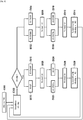
- the figure 2 is a flowchart representing, in general, steps of a method, according to the invention, for controlling a set E of batteries.
- the method is implemented by a DP control device according to the invention.
- control device DP controls a set of two batteries B1 and B2.
- the control device D and the assembly E are included in a control system as presented by the figure 1 .
- the method is initiated during a step E200, considering for example that the last battery Bi having been put to rest is the battery B1 and that the power source GE is initially in an active state.
- the index "i" is a positive integer between 1 and the number of batteries in the set E, that is to say between 1 and 2 in this example, initialized during step E200 to the value 1.
- Battery B1 can be considered as the last battery to be put to rest because its charge level is lower than that of battery B2.
- control device DP monitors info-disp information representative of the state of activity of the power source GE.
- the monitoring step E202 is included in a loop Bcl which includes a step E203 waiting for a TIMER duration between two successive iterations of the monitoring step E202.
- the control device DP continues to command the recharging of the battery B1 (E204) and the return to rest of the battery B2 (E206).
- control device DP obtains information MESi indicating whether the level of charge of the battery on recharge B1 (E204) has reached the determined level NR MIN .
- step E208 is followed by recharging E204 of the battery B1 and putting E206 to rest. of battery B2.
- the control device changes the value of the index i during a step E210 and again executes the monitoring step E202.
- the index i relates to the last battery having been put to rest, which is in this example of implementation, the battery B2.
- the command device DP commands, the recharging E204 of the battery B2 up to the determined level of charge NR MIN and putting E206 of battery B1 to rest.
- the change E210 of the index i is an incrementation by a unit if i is strictly less than the number n of batteries, or an assignment of the value 1 if i is equal to n.
- control device DP obtains, during a step E220, information MESi indicating that the charge level of the discharged battery B1 (E216) has reached the determined level ND MIN , the control device changes the value of the index i during step E210 and again executes the monitoring step E202.
- the DP device alternately changes the battery to be recharged (E204) or discharged (E216), and therefore the battery to be put to rest (E206 or E218).
- the monitoring step E202 is repeated in a loop according to a countdown timer with a TIMER duration.
- the monitoring step E202 can be triggered on reception of a message sent by another device.
- the monitoring step E202 can be triggered following a change E210 in the value of the index i.
- the control device DP puts the two batteries B1 and B2 at rest.
- the figure 3 is a flowchart representing steps of a method for controlling a set E of two batteries B1 and B2 in accordance with an embodiment of the invention. The method is implemented by the DP control device according to the invention and included in the control system described with reference to the figure 1 .
- the consumer device BTS is supplied either by the generator GE, or by one of the batteries B1 or B2.
- control device DP controls the batteries B1 and B2 of the assembly E, but also the state of activity of the generator GE.
- the method is initiated during a step E300.
- the GE generator set is initially stopped.
- the control device DP obtains info-disp information representative of the state of activity of the power source GE, this information being provided in this example by the control device itself . This information indicates that the GE source is in the inactive state.
- the device DP controls the electrical circuits corresponding to the battery B1 for its discharge E002 up to a determined charge level ND MIN considered to be low, for example of 0%.
- the device DP puts the battery B2 to rest, by controlling the opening of the charging and discharging circuits corresponding to the battery B2 for putting it to rest E004.
- control device DP receives information mesl representative of the level of charge of the battery B1. This information indicates that the charge level of battery B1 has reached the charge level ND MIN of 0%.
- the device DP commands a discharge E010 of the battery B2 up to a determined charge level ND MIN considered to be low, for example of 0%.
- the consumer device BTS is then supplied by the battery B2.
- the control device DP commands the battery E1 to be put to rest E008, simultaneously with the discharge E010.
- the control device DP receives second information mes2 representative of the level of charge of the battery B2. This information indicates that the charge level of battery B2 has reached the determined charge level ND MIN of 0%.
- the consumer device BTS is then supplied directly by the power source GE.
- step E302 the info-disp information then indicates that the activity state of the power source GE is active.
- the last battery to be put to rest (E008) is battery B1. Consequently, the device DP commands a recharge E016 of this battery B1 up to a determined charge level NR MIN considered to be high, for example of 100%, and simultaneously, a resting E018 of the battery B2.
- the generator GE supplies both the consumer device BTS and a battery among B1 and B2.
- the control device DP receives information mes1 representative of the charge level of the battery B1, this information indicating that this battery B1 is charged at the level NR MIN considered to be high, of 100%.
- the device DP On receipt of this mesl information, the device DP simultaneously controls a standby E022 of the battery B1 and a recharge E024 of the battery B2 up to a determined charge level NR MIN , for example of 100%.
- control device DP receives information mes2 representative of the charge level of the battery B2, this information indicating that this battery B2 is charged at the determined high level NR MIN of 100%.
- control device DP controls during a step E028 the deactivation of the source GE.
- each of the two batteries B1 and B2 is put to rest between each recharge and each discharge.
- control device DP stops the source GE (E208) only when all the batteries B1 and B2 have charge levels considered to be high.
- control device DP can stop the source GE as soon as the charge level of one of the batteries B1 or B2 is considered to be high.
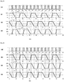
- the figure 4 is a timing diagram representing the different stages of the control process in accordance with the embodiment of the invention described with reference to the figure 3 .
- This chronogram represents the evolution of the charge levels of batteries B1 and B2 as a function of time, in hours.
- the two batteries B1 and B2 have the same nominal voltage.
- the battery B1 is made of Lithium with a nominal capacity slightly lower than that of a conventional HGB system of the prior art, for example a capacity of 90%.
- an HGB power system of the prior art comprises a single battery or several batteries connected in parallel and operating in parallel both in charging and discharging.
- the second battery B2 covers only the duration of the resting of the battery B1.
- the nominal capacity of battery B2 is lower than that of battery B1.
- the battery B2 is also made of Lithium, but it can be of another type.
- Battery B1 (E002) is discharged and battery B2 (E004) is put to rest on the figure 4 from time 0 until the 5th and a half hours.
- Putting the battery B1 (E008) to rest and discharging the battery B2 (E010) last from the 5th and a half hours to the 6th hour.
- the two batteries B1 and B2 being discharged, the step E014 of activation of the source GE is implemented at the 6th hour.
- Charging of battery B1 (E016) and resting of battery B2 (E018) last from the 6th hour until the 7th and a half hours, and they are followed by the resting of battery B1 (E022 ) and recharging the battery B2 (E024) until the 8th hour when step E028 is implemented to deactivate the generator.
- a cyclic sequence lasting 8 hours is applied alternately between the batteries B1 and B2, comprising a discharge, followed by putting to rest, then recharging, and then another put to rest.
- the discharge, recharge and standby times are different for each of the B1 and B2 batteries.
- the application of this cyclic sequence to the battery B2 is delayed by 5 and a half hours compared to its application to the battery B1.
- a cyclic sequence C1 lasting 8 hours is applied to the battery B1, comprising a discharge of 5 and a half hours, followed by a quiescent of half an hour, followed by a recharging d 'an hour and a half, followed by another half hour rest.
- Another cyclic sequence C2 also lasting 8 hours is applied to the battery B2, comprising a discharge of half an hour, followed by putting to rest for an hour and a half, followed by a recharge d 'half an hour, followed by another 51 ⁇ 2 hour rest.
- the organization chart described with reference to the figure 2 also conforms to the embodiment described by the timing diagram of the figure 4 , the index i being initialized (E200) to the value 1, the info-disp information being initially negative and the step E202 of monitoring the activity state of the source being implemented after each execution of the step E210 of modifying the index i, without taking account of a loop Bcl.
- the figure 5 is a timing diagram representing the different stages of the control method in accordance with another embodiment of the invention.
- This chronogram represents the evolution of the charge levels of batteries B1 and B2 as a function of time, in hours.
- the embodiment described here is similar to the mode described with reference to figures 3 and 4 , the two batteries B1 and B2 still having the same nominal voltage, but, in this mode, the batteries B1 and B2 also have the same nominal capacity.
- the sum of the capacities of the batteries B1 and B2 may correspond approximately to the installed capacity of batteries of an HGB system of the prior art.
- control device DP controls the starting of the power source GE.
- the determined charge level considered to be low ND MIN is not zero, for example 10%. Therefore, at a given time, at least one of the two batteries has a non-zero charge level, which makes it possible to guarantee the supply of the BTS consumer device in the event that the consumer device could not be supplied by the GE source due to a breakdown of the GE source, for example, or a break between the GE source and the BTS consumer device.
- a tolerance is added to an intervention time for maintenance, to repair the GE source or to connect the GE source to the BTS consumer device for example.
- This tolerance corresponds to the discharge time of a battery up to a zero ND MAX charge level.
- the initial NR MIN charge level is lower than the NR MAX level makes it possible to maximize the efficiency of the GE source by recharging one of the batteries of this NR MIN charge level from 90% to the NR MAX level of 100% while the GE source supplies the BTS consumer device simultaneously with the resting of the other battery having a low charge level ND MIN of 10%.
- this case occurs from the 5th hour and a half to the 6th hour, from the 13th hour and a half to the 14th hour and from the 21st hour and a half to the 22nd hour.
- the evolution of the chronogram of the figure 5 is explained below.
- the state of the GE power source is inactive.
- control device DP controls the discharge of the battery B1 up to a determined charge level ND MIN , of 10% by way of example, and the setting in B2 battery rest.
- the device DP receives information mes1 indicating that the charge level of the battery B1 has reached the determined charge level ND MIN of 10%.
- the control device DP then controls the starting of the power source GE, in a similar manner to step E014 described with reference to the figure 3 .
- the control device DP commands the resting of the battery B1 and the recharging of the battery B2 from its charge level NR MIN to 90% at a determined charge level NR MAX 100%.
- the efficiency of the GE source is maximized because the GE source supplies the battery B2 in addition to the BTS consumer device.
- the control device DP receives information mes2 indicating that the battery B2 is charged at the level 100%, it therefore commands the putting to rest of this battery B2 and the recharging of the battery B1 to a level of determined load of 90%.
- control device DP receives information mes1 indicating that the battery B1 is charged at the charge level of 90%.
- the control device DP then controls the stopping of the power source GE, in a similar manner to step E028 described with reference to the figure 3 .
- the control device DP controls the discharge of the battery B2 to supply the consumer device BTS, from its current charge level of 100% to the determined charge level ND MIN of 10%. Simultaneously, the device DP controls the putting to rest of the battery B1.
- the control device DP receives information mes2 indicating that the battery B2 is discharged at the ND MIN level of 10%, it therefore commands the resting of this battery B2, the switching on of the source GE and recharging the B1 battery from its current charge level of 90% to a determined NR MAX charge level of 100%.
- the control device DP receives information mes1 indicating that the level of charge of the battery B1 has reached the determined level NR MAX of by 100%, the device then commands the putting to rest of the battery B1 and the recharge the B2 battery to 90% NR MIN determined charge level.
- the control device DP receives information mes2 indicating that the level of charge of the battery B2 has reached the determined level NR MIN of 90%, the device then commands the putting to rest of this battery B2, the setting when the GE source is stopped and the B1 battery discharged to supply the BTS consumer device, up to the determined charge level of ND MIN of 10%.
- the situation of the control system is similar to its initial situation at time 0: the state of the GE source is inactive and the charge levels of the two batteries B1 and B2 are 90%. The steps already described are repeated.
- This sequence C3 comprises a discharge up to the ND MIN level, followed by a setting rest, then a first recharge to the NR MIN level followed by another quiescence, then a second recharge to the NR MAX level followed by another quiescence.
- the durations of the discharge, the first and second recharging and the rest periods included in the sequence C3 are identical for the two batteries B1 and B2.
- the two batteries B1 and B2 having the same capacity, the evolution of their charge levels is identical but with a time difference of 8 hours in this example.
- each battery B1 and B2 has a capacity half that of a battery of an HGB system of the prior art, the GE source starts twice as often, but its operating time is the same. According to data from manufacturers of generator sets, up to ten starts per day does not reduce the life of a GE generator and its starter.
- the figure 6 is a timing diagram representing the different stages of a control method in accordance with an embodiment of the invention.
- the assembly E comprises three batteries, B1, B2 and B3.
- the DP control device controls the three batteries B1, B2 and B3, as well as the power source GE (generator).
- the control device DP controls, at a given instant, the recharging or discharging of a battery of the assembly E and the putting to rest of the two other batteries of the assembly E.
- the three batteries B1, B2 and B3 all have the same nominal voltage and the same nominal capacity, for example a nominal voltage of 48V and a nominal capacity of 300 Ah.
- the operating voltage of the battery can for example vary from 44V to 56V in operation.
- the nominal capacity of each of them is equal to one third of a nominal capacity of a battery of an HGB system of the prior art, for example 100 Ah
- the recharge and discharge times of each of the batteries B1, B2 and B3 are then shorter than those of the battery of the prior art, but putting the batteries B1, B2 and B3 to rest makes it possible to extend their lifetimes.
- control device DP controls the discharge of the battery B2 to supply the consumer device BTS and the resting of the other batteries B1 and B3.
- the DP control device receives information mes2 indicating that the charge level of the battery B2 is 0%. Two batteries (B2 and B3) are discharged, the control device DP then controls the starting of the source GE to supply the consumer device BTS and charge the battery B3 which was at rest.
- the control device DP receives information mes3 indicating that the charge level of the battery B3 is 100%. Two batteries (B1 and B3) are charged, the command DP then commands the stopping of the source GE, the discharge of the battery B1 which was at rest, and the putting at rest of the other batteries B2 and B3.
- the situation at the 5th and a half hour is similar to the initial situation: the state of the GE source is inactive, two batteries have a charge level of 100% and the third battery has a charge level of 0%.
- the continuation of the stages presented on the chronogram of the figure 6 is not described because these steps are similar to the previous steps (from time 0 to the 5th and a half hours) already described.
- This sequence C4 comprises a discharge up to the charge level of 0%, followed by a quiescent, then a recharging up to the charge level of 100% followed by another quiescent.
- this cyclic sequence C4 is applied alternately to the battery B2, then the battery B1, then the battery B3.
- the discharging, recharging and resting times are identical for all the batteries B1, B2 and B3.
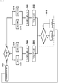
- the figure 7 is a summary flowchart of the steps of a method for controlling a set E of batteries in accordance with an embodiment of the invention, similar to the mode described with reference to figure 6 , in which the set E of batteries comprises a number n of batteries, where n is an integer greater than or equal to 2.
- control device DP monitors the activity state of the power source GE.
- the control device DP controls, during two simultaneous steps E804 and E806, the recharging of a battery Bi of the assembly E up to a determined level of charge NR MIN considered to be high and the resting of the other batteries of the set E, i being an integer between 1 and n and initialized to a determined value. In the mode described with reference to the figure 6 , i is initialized to the value 2.
- control device DP receives information MESi indicating that the charge level of the battery Bi has reached the level NR MIN considered to be high. Thus, the control device DP controls the stopping of the source GE during a step E810.
- the control device DP modifies during a step E812 the whole number i to change at each battery iteration relating to the recharging step (E804) and thus the batteries relating to standby (E806). If the integer i is equal to the number of batteries n, then i is reset to 1, otherwise i is incremented by one.
- control device DP controls, during two simultaneous steps E816 and E818, the discharge of the battery Bi of the assembly E up to a determined charge level ND MIN considered weak and the rest of the other batteries in set E.
- the control device DP receives information MESi indicating that the charge level of the battery Bi has reached the level ND MIN considered to be low. Thus, the control device DP controls the starting of the source GE during a step E822.
- the control device DP modifies during a step E812 the whole number i to change the battery to be discharged (E816) and the batteries to be put to rest (E818) . If the integer i is equal to the number of batteries n, then i is reset to 1, otherwise i is incremented by one.
- the figure 8 is a timing diagram representing the different stages of a control method in accordance with an embodiment of the invention, which differs from the mode described with reference to figures 6 and 7 in that the nominal capacity of each of the batteries B2 and B3 is equal to half that of the battery B1.
- the batteries B2 and B3 are recharged, discharged and put to rest simultaneously.
- the C4 cyclic sequence described with reference to figure 6 is applied to each of the batteries B1, B2 and B3.
- the sequence C4 is applied alternately between the battery B1 on the one hand, and simultaneously the batteries B2 and B3 on the other hand.
- the figure 9 is a timing diagram representing the different stages of a control method in accordance with an embodiment of the invention, in which the set of batteries E comprises 4 batteries B1 to B4 all having the same nominal capacity.
- the control device DP controls the resting of the battery B1 after each recharge and after each discharge of this battery B1.
- the other batteries in set E have simultaneous recharging and discharging cycles, without being put to rest.
- Charging of battery B1 is simultaneous with recharging of other batteries to increase the efficiency of the GE source.
- the discharge of the battery B1 is also simultaneous with the discharge of the other batteries.
- the figure 10 is a timing diagram representing the different stages of a control method in accordance with another embodiment of the invention in which the battery set E also includes 4 batteries B1 to B4 all having the same nominal capacity.
- This mode differs from the mode described with reference to the figure 9 in that the control device DP controls the resting of each of two batteries B1 and B4 of the assembly E after each recharge and each discharge of the battery in question.
- a cyclic sequence C5 comprising a discharge followed by a quiescent and a recharge followed by another quiescent is applied alternately between the batteries B1 and B4.
- the mode illustrated by figure 10 makes it possible to extend the life of the battery B4, in addition to that of the battery B1, while maintaining an acceptable efficiency of the GE source despite the reduction in charge (3 batteries at the same time).
- the figure 11 illustrates an architecture of a control system for a set E of batteries B1 and B2, in accordance with an embodiment of the invention.
- This system comprises two power sources: an unreliable electrical network N_ELEC and a generator GE, the control device DP according to the invention and a consumer device HOSP.
- the HOSP consumer device is an electronic medical device, requiring permanent availability of an electric current.
- the system presented to the figure 11 is located in a rural area without a reliable electricity network.
- control device DP controls a set of two batteries B1 and B2, as well as the source GE, but does not control the state of activity of the source N_ELEC.
- each of the batteries B1 and B2 comprises an electronic management entity, associated with the battery for its management, and called BMS (for "Battery Management System” in English).
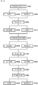
- the figure 12 is a flowchart representing steps of a method for controlling a set E of two batteries B1 and B2 in accordance with an embodiment of the invention. The method is implemented by the DP control device according to the invention and included in the control system described with reference to the figure 11 .
- the control device DP obtains info-disp information representative of the state of activity of the electrical network N_ELEC. This information indicates that the source N_ELEC is in active state.
- the info-disp information on the activity status of the N_ELEC source is received from an alarm device.
- this info-disp information is monitored by the control device DP periodically permanently, for example every 2 seconds.
- the DP device controls the recharging of the batteries B1 and B2.
- the HOSP consumer device is supplied directly by the N_ELEC source.
- the device DP controls the recharging of the battery B1 up to a determined charge level, of 100% for example. Simultaneously, during a step E106, the device DP puts the battery B2 at rest.
- control device DP receives information mes1 representative of the charge level of the battery B1, indicating that the charge level of the battery B1 is 100%. The DP device then begins to recharge the second battery B2.
- control device DP controls the resting of the battery B1 and the recharging of the battery B2 up to a determined charge level, for example of 100%.
- the control device DP obtains the info-disp information indicating that the state of the source N_ELEC has become inactive, even before that the charge level of battery B2 has reached the determined level of 100%.
- the control device DP controls the discharge of the battery B1 during a step E116 up to a determined charge level, of 0% for example, and puts at rest the battery B2 during a step E118 simultaneous with step E116.
- the DP device selects the discharge of the last battery to be put to rest, namely battery B1.
- control device DP receives information mes1 indicating that the level of charge of the battery B1 has reached the level of 0%.
- the control device DP then controls the supply of the consumer device HOSP by the battery B2. During two simultaneous steps E122 and E124, the control device DP controls the resting of the battery B1 and the discharge of the battery B2 up to a determined charge level, for example of 0%.
- control device DP receives information mes2 indicating that the level of charge of the battery B2 has reached the level of 0%.
- control device DP controls, during a step E128 the starting of the generator generator GE to supply the consumer device HOSP and recharge batteries B1 and B2 in an alternative way.
- the power source is an unreliable N_ELEC electrical network, which may have several interruptions or provide an electrical current or voltage with an unstable value.
- the power source is a SOL generator of electrical energy from solar energy.
- the power source is a WND generator of electrical energy from wind energy.
- control system includes several power sources, of the same type or of different types.
- control system comprises at least two power sources, one of which is a Stirling type generator.
- This type of generator can cover the power of use, that is to say power the BTS consumer device, but not the recharging of the batteries.
- the consumer device can be a device other than a BTS base station or an HOSP medical device.
- the consumer device is an electronic device which requires to be supplied electrically with a minimum threshold of availability and / or a minimum threshold of stability at the level of the current intensity, the voltage or the electric power which supplies it.
- control system includes several consumer devices.
- At least one of the batteries B1 and B2 controlled by the control device is of the Lead, or Nickel type or a hot battery.
- the batteries B1 and B2 of the set E of batteries are not necessarily of the same technology.
- the data mes1, mes2, mes3 representative of the charge levels of the batteries of the set E are based on current or voltage measurements at the level of the batteries.
- the data mes1, mes2, mes3 representative of the charge levels of the batteries of the set E are based on estimates, using for example machine learning algorithms.
- the data mes1, mes2, mes3 representative of the battery charge levels are based on TIMER countdown counters. For example, it can be estimated that battery B1, whose charge level is presented to the figure 4 , discharges after 5 and a half hours, and charges in 1 and a half hours.
- the figure 13 presents a functional architecture of a DP device, according to the invention, as well as two power sources of different types: a first source of the GE generator type, and a second source of the SOL solar panel type, WND wind turbine or a electrical network N_ELEC.
- the DP control device controls a set of two batteries B1 and B2 which can each be connected to a power source and to a consumer device.
- the SURV monitoring module is configured to monitor info-disp information each representative of an activity state of a GE, SOL, WND or N_ELEC power source. This information can be obtained by receiving a message from the source in question or by reading from a memory.
- this info-disp information is transmitted from the CONT control module to the SURV monitoring module.
- connection means K1, K'1 relating to a battery B1 are configured to provide an electrical connection between the battery B1 and a power source N-ELEC, GE, SOL or WND to recharge the battery, or provide an electrical connection between the battery B1 and a consumer device to discharge the battery, or electrically disconnect the battery B1 from any power source and from any consumer device, to put the battery at rest.
- the discharge circuit CD allows the passage of an electric current for discharging the battery B1
- the circuit comprising the means K'1 called CR charging circuit
- the discharge can be optimized by closing K'1 to avoid Joule losses in the diode.
- connection means K1, K'1, K2 and K'2 are power switches. These switches can be electromechanical such as a relay or electronic such as an MOS transistor.
- the diode functions D1 and D2 can be passive diodes or controlled switches, for example a transistor controlled by an electronic circuit performing the same function as a passive diode.
- the diode D1 (respectively D2) allows the instantaneous discharge of the battery B1 (respectively B2) and therefore to obtain an uninterrupted power supply when the N-ELEC power sources, GE, SOL or WND no longer provide current.
- Closing the switch K'1 makes it possible to recharge the battery B1 (respectively B2), but also during the discharge phases to eliminate by bypass the Joules losses and the voltage drop in the diode function D1 (respectively D2) due to the threshold voltage of the diode function D1 (respectively D2).
- the opening of the torque K1 and K1 '(respectively K2 and K2') allows the battery B1 (respectively B2) to be put to rest and to stop any discharge below a critical voltage threshold for electrochemistry below which there is a risk of irreversibility of the reactions in the elements, in particular by dendrite metallization and internal short circuit with heating and starting of an uncontrollable oxidation or combustion reaction.
- the recharging and discharging commands are such that the consumer device BTS, HOSP, is supplied without interruption either by the power source N-ELEC, GE, SOL, or WND, or by the discharge of a said battery, B1 or B2.
- the DC coupling module commands to close the contactors K1 and K'1 and to open K2 and K'2.
- the battery B1 discharges via the circuit comprising the switch K'1 without loss in the diode D1. Battery B2 is put to rest.
- the battery B1 is discharged, the DC coupling module commands to open K'1, then the CONT control module commands to start the GE source.
- the DC coupling module commands to close K'2 there is not a current flowing between the batteries B1 and B2 because the switch K'1 is open. Then, the DC coupling module commands to open K1, then to close K2. In this way, the battery B2 is charging and the battery B1 is put to rest.
- the DC coupling module commands to open K'2, close K'1, then open K2.
- the DC coupling module commands to open K'1 then to close K'2 and K2.
- connection means K1, K'1, K2, K'2, D1 and D2 are included in the control device DP.
- these means are included in another device or another box than the DP control device, but are controlled by the DC coupling module of the DP control device.
- the charging and discharging circuits of a battery can be controlled independently of each other.
- the independence of the charge and discharge circuits makes it possible to introduce a certain redundancy.
- the discharge of the battery B1 can occur either by closing the switch K1, or by closing the switch K'1.
- the CONT control module is configured to control the activity state of a power source, for example of the GE generator type.
- the COM communication module is configured to obtain at least one piece of information mes1 (resp. Mes 2) representative of a charge level of a battery B1 (resp. B2), to determine, as a function of this information mes1 (or mes2 ), which battery among B1 and B2 to recharge or discharge.
- the level of charge SoC (for “State of Charge” in English) of a battery can be expressed in percentage by the ratio between the available charge Q in the battery and the maximum capacity Cmax of this battery.
- the charge Q and the charge level SoC can be determined from the battery voltage if it reflects the state of charge.
- the voltage is high at the end of the charge, for example greater than 3.45 V x k for Lithium Iron Phosphate (LFP) batteries, k being the number of elements in series to constitute the battery.
- LFP Lithium Iron Phosphate
- the voltage is low at the end of discharge, for example less than 3 V x k for these types of batteries.
- the voltage is not a sufficiently precise indicator for the intermediate states of charge and this measurement can be supplemented by a counter accumulating the charge Q at a given instant, this charge Q being assumed to be contained in the battery and bounded between 0 and the maximum capacity value Cmax.
- the calculation of the charge Q uses at least current and time measurements, or even other measurements such as temperature and other information stored as manufacturer's reference data or historical data acquired during the use of the battery. .
- the state of health is affected by the age of the battery, also called calendar aging, cycle history, temperature, time spent at different depths of discharge, charging current, any abuse suffered (overcharging, under-discharge, short circuit), poor maintenance, etc.
- the maximum value is corrected, for example as a function of the nominal capacity of the battery, or as a function of the state of health, or of the temperature.
- the measurements of the charge levels of a battery can be acquired beforehand by a BMS entity associated with this battery.
- the information mes1 or mes2 is recovered via a communication link, for example a link of analog, modbus, CAN, FIP, Ethernet or another type.
- At least one B1 battery is made of Lithium.
- the two parallel circuits, for recharging and discharging, comprising the means K1, K'1 and D1 relating to this battery B1 are included in the electronic management entity BMS associated with the battery B1.
- the DP control device has the architecture of a computer, as illustrated in the figure 14 . It notably includes a processor 7, a random access memory 8, a read-only memory 9, a non-volatile flash memory 10 in a particular embodiment of the invention, as well as communication means 11. Such means are known per se and are not described in more detail here.
- the read-only memory 9 of the control device DP according to the invention constitutes a recording medium in accordance with the invention, readable by the processor 7 and on which a computer program Prog according to the invention is recorded.
- the memory 10 of the control device DP makes it possible to record variables used for the execution of the steps of the invention, such as the data mesl, mes2, mes3 representative of the charge levels of the batteries, the info-disp information representative of the power source activity states, a value from a TIMER countdown timer used to estimate a battery charge level.
- the Prog computer program defines functional and software modules, configured to drive batteries. These functional modules rely on and / or control the hardware elements 7-11 of the DP control device mentioned above.
Abstract
Chacune des batteries de l'ensemble est reliée à un circuit électrique reliant une source d'alimentation à un dispositif consommateur pour former un circuit électrique commandable dit de recharge, reliant la batterie à la source d'alimentation, et un circuit électrique commandable dit de décharge, reliant la batterie au un dispositif consommateur. Le procédé comprend au moins:- une recharge d'une dite première batterie de l'ensemble, simultanée avec une mise au repos d'au moins une autre batterie de l'ensemble, la recharge de la première batterie étant suivie par une mise au repos de cette première batterie; ou- une décharge d'une dite première batterie de l'ensemble, simultanée avec une mise au repos d'au moins une autre batterie de l'ensemble, la décharge de la première batterie étant suivie par une mise au repos de cette première batterie,- une recharge de n'importe laquelle des batteries consiste à commander une fermeture de son circuit de recharge pour la recharger par la source d'alimentation ;- une décharge de n'importe laquelle des batteries consiste à commander une ouverture de son circuit de recharge et une fermeture de son circuit de décharge pour la décharger et alimenter le dispositif consommateur;- une mise au repos de n'importe laquelle des batteries consiste à commander une ouverture de ses circuits de recharge et de décharge ;le dispositif consommateur étant alimenté soit par la source d'alimentation, soit par la décharge d'une batterie.Each of the batteries in the assembly is connected to an electrical circuit connecting a power source to a consumer device to form a controllable electrical circuit called recharging, connecting the battery to the power source, and a controllable electrical circuit called discharge, connecting the battery to a consumer device. The method comprises at least: - a recharge of a said first battery of the assembly, simultaneous with the resting of at least one other battery of the assembly, the recharging of the first battery being followed by an activation rest of this first battery; or- a discharge of a said first battery of the assembly, simultaneous with the resting of at least one other battery of the assembly, the discharge of the first battery being followed by a resting of this first battery , - recharging any of the batteries consists in ordering a closure of its recharging circuit in order to recharge it by the power source; - discharging any of the batteries consists in commanding an opening of its circuit recharging and closing its discharge circuit to discharge it and supply the consumer device; - putting any of the batteries to rest consists in ordering an opening of its recharge and discharge circuits; the consumer device being supplied either by the power source, either by discharging a battery.
Description
L'invention se rapporte au domaine général de batteries d'accumulateurs électriques rechargeables. Elle concerne plus particulièrement l'alimentation électrique de dispositifs électroniques situés dans des zones sans réseau électrique fiable, en d'autre mots, sans réseau électrique qui respecte des exigences strictes en termes de disponibilité et de stabilité de courant, de tension et/ou de puissance fournie.The invention relates to the general field of rechargeable electric storage batteries. It relates more particularly to the electrical supply of electronic devices located in areas without a reliable electrical network, in other words, without an electrical network which meets strict requirements in terms of availability and stability of current, voltage and / or power supplied.
Pour alimenter des dispositifs électroniques consommateurs dans des zones non couvertes par des réseaux électriques, une première solution consiste à utiliser des groupes électrogènes, par exemple des moteurs Diesel produisant de l'énergie électrique.To power consumer electronic devices in areas not covered by electrical networks, a first solution consists in using generator sets, for example diesel engines producing electrical energy.
Cependant, les groupes électrogènes sont en général surdimensionnés par rapport à la puissance d'utilisation des dispositifs consommateurs qu'ils alimentent, ce qui conduit à un rendement assez faible et à une usure prématurée du groupe électrogène. A titre d'exemple, les puissances d'utilisation requises pour alimenter un équipement de télécommunications et un équipement de conditionnement d'air sont chacune de l'ordre de 1 à 4 kW. Dans ce cas, le taux moyen de charge d'un groupe électrogène qui alimente ces deux équipements est seulement compris entre 10 et 50%.However, the generator sets are generally oversized in relation to the power of use of the consumer devices which they supply, which leads to a fairly low efficiency and to premature wear of the generator set. By way of example, the powers of use required to supply telecommunications equipment and air conditioning equipment are each of the order of 1 to 4 kW. In this case, the average charge rate of a generator that powers these two pieces of equipment is only between 10 and 50%.
Une deuxième solution consiste à associer une batterie à un groupe électrogène pour former un système hybride d'alimentation HGB (pour « Hybrid Genset Battery » en anglais). Deux phases sont alternées : pendant une première phase, le groupe électrogène alimente les dispositifs consommateurs et charge aussi la batterie, puis pendant une deuxième phase, le groupe électrogène est mis en arrêt et la batterie se décharge pour alimenter les dispositifs consommateurs. La première et la deuxième phase peuvent durer chacune quelques heures. Cette solution permet d'allonger la durée de vie du groupe électrogène en réduisant son temps de fonctionnement, le coût de sa maintenance et en le faisant fonctionner à plus haut taux de charge (puisqu'il alimente la batterie en plus des dispositifs consommateurs), idéalement à 75% pour obtenir une plus faible consommation de combustible.A second solution consists in associating a battery with a generator to form a hybrid HGB supply system (for "Hybrid Genset Battery" in English). Two phases are alternated: during a first phase, the generator supplies the consumer devices and also charges the battery, then during a second phase, the generator is switched off and the battery discharges to supply the consumer devices. The first and second phases can each last a few hours. This solution makes it possible to extend the life of the generator by reducing its operating time, the cost of its maintenance and by making it operate at a higher charge rate (since it supplies the battery in addition to the consumer devices), ideally 75% for lower fuel consumption.
Dans le cas de disponibilité d'un réseau électrique non fiable, par exemple à disponibilité réduite de quelques heures par jour, une troisième solution pour alimenter des dispositifs électroniques consommateurs consiste à associer une batterie au réseau électrique non fiable : la batterie se charge et est maintenue chargée tant que le réseau électrique est disponible en même temps que les dispositifs consommateurs sont alimentés par ce réseau électrique, et lorsque le réseau électrique n'est plus disponible, la batterie se décharge pour alimenter les dispositifs consommateurs en autonomie de plusieurs heures.In the case of availability of an unreliable electrical network, for example with reduced availability of a few hours per day, a third solution for supplying consumer electronic devices consists in associating a battery with the unreliable electrical network: the battery is charged and is kept charged as long as the electrical network is available at the same time as the consumer devices are supplied by this electrical network, and when the electrical network is no longer available, the battery discharges to supply the consumer devices with autonomy for several hours.
La deuxième et la troisième solution, se basant toutes les deux sur l'utilisation d'une batterie en alternance avec une autre source d'alimentation, présentent des inconvénients liés à la durée de vie des batteries, à leurs coûts et/ou à des contraintes d'utilisation de ces batteries.The second and third solutions, both based on the use of a battery in alternation with another power source, have drawbacks linked to the lifetime of the batteries, their costs and / or constraints on the use of these batteries.
En ce qui concerne les batteries actuellement disponibles et leurs utilisations :
- les batteries les plus utilisées sont au Plomb-acide. Leur durée de vie en cycles de charge et de décharge est limitée en particulier à haute température ambiante telle qu'une température supérieure à 30°C. En Afrique par exemple, la durée de vie d'une batterie au Plomb rechargeable qui fait jusqu'à une dizaine de cycles de charge/décharge par semaine à 50 % de sa capacité n'est souvent que de 2 à 4 ans. Cependant, une batterie au Plomb peut comporter plusieurs branches mises en parallèle à des états de charge différents, ce qui permet de remplacer une branche défectueuse par une autre sans risque de coupure du système.
- des informations de constructeurs et des tests sur des batteries Lithium montrent que leur durée de vie peut atteindre de 6 à 7 ans en cycle profond i.e. en cycle de charge et décharge dans lequel la décharge est continue jusqu'à ce que la batterie atteigne sa coupure de tension basse, habituellement définie pour 70 à 90 % de décharge. Cependant les batteries Lithium ont un coût initial 3 à 4 fois supérieur à celui des batteries au Plomb et sont donc encore peu utilisées (quelques pourcents du marché). De plus, la mise en parallèle des batteries Lithium est assez complexe si ces batteries ne sont pas dans un même état de charge, i.e. à une même tension.
- les batteries dites chaudes comme les batteries Sodium fondu ou les batteries Chlorure de Nickel ont un bon rendement électrochimique, mais leur rendement global avec un maintien en température à environ 300°C est de l'ordre de 50 à 75%. De plus, en cas de défaillance au niveau de l'autre source d'alimentation (le groupe électrogène ou le réseau électrique non fiable), il faut que le temps d'intervention ne dépasse pas le temps de refroidissement de la batterie chaude, car une batterie refroidie peut demander jusqu'à plusieurs jours pour remonter lentement en température afin de ne pas briser la céramique interne de la batterie. Les batteries chaudes ne sont donc utilisées qu'avec d'autres sources d'alimentation fiables et dans des zones rapidement accessibles pour la maintenance.
- the most used batteries are lead-acid. Their lifetime in charge and discharge cycles is limited in particular at high ambient temperature such as a temperature above 30 ° C. In Africa, for example, the life of a rechargeable lead-acid battery which performs up to ten charge / discharge cycles per week at 50% of its capacity is often only 2 to 4 years. However, a lead-acid battery can have several branches placed in parallel with different charge states, which makes it possible to replace a defective branch with another without risk of cutting the system.
- information from manufacturers and tests on Lithium batteries show that their lifespan can reach 6 to 7 years in deep cycle ie in charge and discharge cycle in which the discharge is continuous until the battery reaches its cut-off low voltage, usually defined for 70 to 90% discharge. However, Lithium batteries have an initial cost 3 to 4 times higher than that of Lead batteries and are therefore still little used (a few percent of the market). In addition, putting Lithium batteries in parallel is quite complex if these batteries are not in the same state of charge, ie at the same voltage.
- so-called hot batteries such as molten Sodium batteries or Nickel Chloride batteries have good electrochemical efficiency, but their overall efficiency with maintaining the temperature at around 300 ° C is of the order of 50 to 75%. In addition, in the event of a failure at the other power source (the generator or the unreliable power grid), the intervention time must not exceed the cooling time of the hot battery, because a cooled battery can take up to several days to slowly rise in temperature so as not to break the internal ceramic of the battery. Hot batteries are therefore only used with other reliable power sources and in areas quickly accessible for maintenance.
les batteries REDOX ou « à flux » telles que les batteries à flux de sels de vanadium oxydo-réducteur ont l'avantage de pouvoir ajouter de la capacité en augmentant la taille d'un réservoir externe de liquide. Mais ces batteries ont un rendement modeste en utilisation permanente à cause de fuites électriques entre des éléments en série via les fluides salins conducteurs utilisés et elles demandent beaucoup d'entretien. Par exemple, la batterie REDOX Zinc-Brome, doit être arrêtée une fois par semaine pour sa régénération et son nettoyage automatique interne. De plus, il n'a pas été proposé de fonctionnement en alternance des batteries REDOX avec une autre source d'alimentation.REDOX or “flow” batteries such as oxidation-reduction vanadium salt flow batteries have the advantage of being able to add capacity by increasing the size of an external liquid reservoir. But these batteries have a modest yield in permanent use because of electrical leaks between elements in series via the conductive saline fluids used and they require a lot of maintenance. For example, the REDOX Zinc-Brome battery must be stopped once a week for its regeneration and internal automatic cleaning. In addition, it has not been proposed to operate alternating REDOX batteries with another power source.
De ce fait, même la deuxième et la troisième solutions décrites précédemment, qui utilisent une batterie associée à une autre source d'alimentation, ne sont pas satisfaisantes.As a result, even the second and third solutions described above, which use a battery associated with another power source, are not satisfactory.
Il existe un besoin en une solution permettant d'alimenter des dispositifs électroniques consommateurs dans une zone ne disposant pas d'un réseau électrique fiable, et qui ne présente pas certains des inconvénients de l'état de la technique.There is a need for a solution for supplying consumer electronic devices in an area which does not have a reliable electrical network, and which does not have some of the drawbacks of the prior art.
L'invention vise un procédé de commande de charge et de décharge de batteries d'un ensemble desdites batteries, chacune de ces batteries étant reliée à un circuit électrique reliant une source d'alimentation à un dispositif consommateur pour former :
- un circuit électrique commandable, dit de recharge, reliant la batterie à la source d'alimentation; et
- un circuit électrique commandable, dit de décharge, reliant la batterie au dispositif consommateur et réalisant une fonction diode pour éviter un courant de circulation entre les batteries, ledit procédé comprenant au moins:
- une recharge d'une dite première batterie de l'ensemble, simultanée avec une mise au repos d'au moins une autre batterie de l'ensemble, dite deuxième batterie, la recharge de la première batterie étant suivie par une dite mise au repos de la première batterie; ou
- une décharge d'une dite première batterie de l'ensemble, simultanée avec une mise au repos d'au moins une autre batterie de l'ensemble, dite deuxième batterie, la décharge de la première batterie étant suivie par une dite mise au repos de la première batterie,
dans ledit procédé :- une dite recharge de n'importe laquelle des batteries consiste à commander une fermeture du circuit électrique de recharge correspondant à cette batterie pour la recharge de la batterie par la source d'alimentation ;
- une dite décharge de n'importe laquelle des batteries consiste à commander une ouverture du circuit électrique de recharge et à commander une fermeture du circuit électrique de décharge correspondants à cette batterie pour la décharge de la batterie pour alimenter le dispositif consommateur ;
- une dite mise au repos de n'importe laquelle des batteries consiste à commander une ouverture des circuits électriques de recharge et de décharge correspondants à cette batterie pour sa mise au repos;
le dispositif consommateur étant alimenté soit par la source d'alimentation, soit par la décharge d'une batterie.
- a controllable electrical circuit, called a recharging circuit, connecting the battery to the power source; and
- a controllable electrical circuit, called a discharge circuit, connecting the battery to the consumer device and performing a diode function to avoid a circulating current between the batteries, said method comprising at least:
- a recharge of a said first battery of the assembly, simultaneous with the resting of at least one other battery of the assembly, called the second battery, the recharging of the first battery being followed by a so-called rest of the first battery; or
- a discharge of a said first battery of the assembly, simultaneous with the resting of at least one other battery of the assembly, called the second battery, the discharge of the first battery being followed by a said resting of the first battery,
in said process:- said recharging of any of the batteries consists in commanding a closure of the electric recharging circuit corresponding to this battery for recharging the battery by the power source;
- said discharge of any of the batteries consists in commanding an opening of the electric recharging circuit and in controlling a closing of the electric discharging circuit corresponding to this battery for discharging the battery to supply the consumer device;
- a said putting to rest of any of the batteries consists in commanding an opening of the electric recharging and discharging circuits corresponding to this battery for putting it to rest;
the consumer device being supplied either by the power source or by the discharge of a battery.
Corrélativement, l'invention vise un dispositif de commande de charge et de décharge de batteries d'un ensemble desdites batteries, chacune de ces batteries étant destinée à être reliée à un circuit électrique reliant une source d'alimentation à un dispositif consommateur pour former un circuit électrique commandable, dit de recharge, reliant la batterie à la source d'alimentation et un circuit électrique commandable, dit de décharge, reliant la batterie au dispositif consommateur et réalisant une fonction diode pour éviter un courant de circulation entre les batteries, le dispositif de commande comporte un module de couplage configuré pour générer au moins:
- une commande de recharge d'une dite première batterie de l'ensemble, simultanée avec une mise au repos d'au moins une autre batterie de l'ensemble, dite deuxième batterie, la recharge de la première batterie étant suivie par une mise au repos de la première batterie; ou
- une commande de décharge d'une dite première batterie de l'ensemble, simultanée avec une mise au repos d'au moins une autre batterie de l'ensemble, dite deuxième batterie, la décharge de la première batterie étant suivie par une mise au repos de la première batterie;
ledit module de couplage étant configurer pour générer les commandes de recharge et les commandes de décharge pour que le dispositif consommateur soit alimenté soit par la source d'alimentation, soit par la décharge d'une dite batterie, - une dite recharge de n'importe laquelle des batteries consiste à commander une fermeture du circuit électrique de recharge correspondant à cette batterie pour la recharge de la batterie par la source d'alimentation ;
- une dite décharge de n'importe laquelle des batteries consiste à commander une ouverture du circuit électrique de recharge et à commander une fermeture du circuit électrique de décharge correspondants à cette batterie pour la décharge de la batterie pour alimenter le dispositif consommateur ;
- une dite mise au repos de n'importe laquelle des batteries consiste à commander une ouverture des circuits électriques de recharge et de décharge correspondants à cette batterie pour sa mise au repos.
- a command for recharging a said first battery of the assembly, simultaneous with putting at least one other battery in the assembly, said second battery, the recharging of the first battery being followed by putting the first battery to rest; or
- a command to discharge a said first battery of the assembly, simultaneous with putting at least one other battery in the assembly, called the second battery, the discharge of the first battery being followed by putting it to rest of the first battery;
said coupling module being configured to generate recharging commands and discharging commands so that the consumer device is supplied either by the power source or by the discharge of a said battery, - said recharging of any of the batteries consists in commanding a closure of the electric recharging circuit corresponding to this battery for recharging the battery by the power source;
- said discharge of any of the batteries consists in commanding an opening of the electric recharging circuit and in controlling a closing of the electric discharging circuit corresponding to this battery for discharging the battery to supply the consumer device;
- a so-called quiescent of any of the batteries consists in commanding an opening of the electric recharging and discharging circuits corresponding to this battery for its quiescence.
Ainsi, selon l'invention le dispositif consommateur est alimenté sans coupure, autrement dit en continu, soit par la source d'alimentation, soit par la décharge d'une batterie.Thus, according to the invention, the consumer device is supplied without interruption, in other words continuously, either by the power source or by the discharge of a battery.
Les caractéristiques et avantages du procédé de commande selon l'invention présentés ci-après s'appliquent de la même façon au dispositif de commande selon l'invention, et vice versa.The characteristics and advantages of the control method according to the invention presented below apply in the same way to the control device according to the invention, and vice versa.
Conformément à l'invention, on dit qu'une recharge et une mise au repos, ou une décharge et une mise au repos sont simultanées ou effectuées simultanément si elles commencent au même moment et se terminent au même moment.According to the invention, it is said that a recharge and a rest, or a discharge and a rest are simultaneous or carried out simultaneously if they start at the same time and end at the same time.
L'invention permet ainsi d'alimenter le dispositif consommateur d'une façon continue (i.e. sans coupure) soit par la source d'alimentation soit par au moins une des batteries parmi l'ensemble de batteries. La mise au repos des batteries est introduite sans réduire l'alimentation du dispositif consommateur.The invention thus makes it possible to supply the consumer device in a continuous manner (i.e. without interruption) either by the power source or by at least one of the batteries among the set of batteries. Putting the batteries to rest is introduced without reducing the supply to the consumer device.
Au sens de l'invention, la mise au repos d'une batterie est sa déconnexion de toute source d'alimentation et de tout dispositif consommateur. Durant cette phase, un niveau de charge de la batterie reste constant.Within the meaning of the invention, putting a battery to rest is its disconnection from any power source and from any consumer device. During this phase, a battery charge level remains constant.
Au sens de l'invention, la recharge d'une batterie est une phase durant laquelle la batterie est alimentée électriquement par la source d'alimentation et emmagasine de l'énergie électrique. Durant cette phase, le niveau de charge de la batterie augmente.Within the meaning of the invention, recharging a battery is a phase during which the battery is supplied electrically by the power source and stores electrical energy. During this phase, the battery charge level increases.
Si le circuit électrique de décharge d'une batterie est fermé, ce circuit de décharge sera court-circuité pendant une recharge de cette batterie.If the electric discharge circuit of a battery is closed, this discharge circuit will be short-circuited during recharging of this battery.
Dans un mode de réalisation, la recharge d'une batterie comporte en outre une ouverture dudit circuit électrique de décharge de cette batterie.In one embodiment, the recharging of a battery further comprises an opening of said electrical circuit for discharging this battery.
Au sens de l'invention, la décharge d'une batterie est une phase durant laquelle la batterie restitue de l'énergie électrique, pour alimenter le dispositif consommateur. Durant cette phase, le niveau de charge de la batterie décroît.Within the meaning of the invention, the discharge of a battery is a phase during which the battery restores electrical energy, to supply the consumer device. During this phase, the battery charge level decreases.
Les circuits de recharge et de décharge d'une batterie peuvent être commandés indépendamment l'un de l'autre.The charging and discharging circuits of a battery can be controlled independently of each other.
Les valeurs nominales de capacité et de tension d'une batterie sont celles définies par le constructeur de la batterie conformément à une norme.The nominal capacity and voltage values of a battery are those defined by the battery manufacturer in accordance with a standard.
Au sens de l'invention, un cycle d'une batterie comporte au moins une recharge et une décharge de cette batterie.Within the meaning of the invention, a cycle of a battery comprises at least one recharging and one discharging of this battery.
Au sens de l'invention, chaque batterie de l'ensemble peut être reliée à une ou plusieurs sources d'alimentation et à un ou plusieurs dispositifs consommateurs.Within the meaning of the invention, each battery of the assembly can be connected to one or more power sources and to one or more consumer devices.
Au sens de l'invention, une batterie peut comporter une seule branche ou plusieurs branches de même tension fonctionnant en parallèle et faites de blocs. Par exemple, une batterie peut comporter deux branches en parallèle de 48V, chaque branche comportant quatre blocs de 12V chacun.Within the meaning of the invention, a battery can comprise a single branch or several branches of the same voltage operating in parallel and made of blocks. For example, a battery can have two branches in parallel of 48V, each branch having four blocks of 12V each.
L'invention permet en particulier d'allonger la durée de vie des batteries grâce au temps de repos qui sépare les phases de recharge et de décharge et/ou vice versa. En effet, les batteries de l'ensemble sont rechargées ou déchargées en alternance.The invention makes it possible in particular to extend the lifespan of the batteries thanks to the rest time which separates the recharging and discharging phases and / or vice versa. Indeed, the batteries of the assembly are recharged or discharged alternately.
Des tests expérimentaux ont pu mettre en évidence une réduction du vieillissement en termes de perte de capacité par cycles grâce à la mise au repos entre les phases de recharge et de décharge des accumulateurs au Lithium et ceci même en les faisant travailler à 100% de leur capacité nominale.Experimental tests have been able to demonstrate a reduction in aging in terms of loss of capacity by cycles thanks to the resting between the recharging and discharging phases of lithium accumulators and this even by making them work at 100% of their nominal capacity.
Par exemple, à une température entre 35 et 45 °C et sur 1000 cycles de recharge et décharge, la mise au repos d'une batterie entre 15 et 30 minutes entre les phases de recharge et de décharge et vice versa permet de réduire la pente de vieillissement d'une dizaine de pourcentages à quelques pourcentages. Dans ces conditions, la durée de vie de la batterie peut atteindre plus de 10 ans. L'utilisation des batteries Lithium peut être alors privilégiée par rapport aux batteries en Plomb vu que sur une telle longue durée de vie, il y aura un retour sur l'investissement du coût initial.For example, at a temperature between 35 and 45 ° C and over 1000 recharge and discharge cycles, putting a battery to rest between 15 and 30 minutes between the recharge and discharge phases and vice versa makes it possible to reduce the slope aging from ten percent to a few percent. Under these conditions, the battery life can reach more than 10 years. The use of Lithium batteries can then be preferred over Lead batteries since, over such a long service life, there will be a return on the investment of the initial cost.
Les batteries de l'ensemble peuvent avoir des capacités nominales différentes ou une même capacité nominale.The batteries in the set can have different nominal capacities or the same nominal capacity.
La mise au repos d'une batterie peut permettre de réduire la température de la batterie, ce qui améliore sa durée de vie, mais aussi réduit le besoin de mettre en marche un équipement de refroidissement de la batterie, tel qu'un climatiseur. L'invention permet donc de réduire la consommation énergétique.Putting a battery to rest can reduce the temperature of the battery, which improves its lifespan, but also reduces the need to turn on battery cooling equipment, such as an air conditioner. The invention therefore makes it possible to reduce energy consumption.
Dans un mode préféré, au moins une batterie dudit ensemble est de type Lithium. Comme mentionné précédemment, la batterie Lithium offre des cycles profonds, travaille entre 80 et 100 % de capacité nominale, et a une plus longue durée de vie que les autres types de batteries. De plus, l'allongement de la durée de vie de la batterie Lithium grâce à la solution proposée par la présente invention permet d'avoir un retour sur l'investissement sur le coût initial de la batterie Lithium.In a preferred mode, at least one battery of said assembly is of the Lithium type. As mentioned before, the Lithium battery offers deep cycles, works between 80 and 100% of nominal capacity, and has a longer lifespan than other types of batteries. In addition, the extension of the service life of the Lithium battery thanks to the solution proposed by the present invention allows a return on the investment on the initial cost of the Lithium battery.
Dans un mode préféré, au moins une batterie dudit ensemble est de type Lithium ou Nickel (par exemple NiCd, NiZn ou NiMH) acceptant suffisamment de puissance en recharge et en décharge pour qu'une seule batterie dudit ensemble puisse d'une part, fournir l'ensemble de la puissance demandée par le dispositif consommateur et d'autre part, accepter la puissance maximale de la source d'alimentation.In a preferred mode, at least one battery of said set is of the Lithium or Nickel type (for example NiCd, NiZn or NiMH) accepting sufficient power in recharge and in discharge so that a single battery of said set can on the one hand all of the power requested by the consumer device and on the other hand, accept the maximum power of the power source.
La capacité de l'ensemble de batteries selon l'invention peut être égale à la capacité d'une seule batterie conformément à une solution d'alimentation de l'art antérieur. Le fait d'avoir un ensemble d'au moins deux batteries ne résulte pas à une augmentation du coût des batteries par rapport aux solutions de l'art antérieur.The capacity of the battery assembly according to the invention can be equal to the capacity of a single battery in accordance with a supply solution of the prior art. The fact of having a set of at least two batteries does not result in an increase in the cost of the batteries compared to the solutions of the prior art.
Dans un mode de réalisation, la mise au repos n'est pas ajoutée systématiquement après chaque recharge et après chaque décharge. Il est possible de mettre une batterie au repos après chaque recharge de cette batterie par exemple, ou après chaque décharge, ou après un nombre donné de cycles. Le gain en termes de durée de vie d'une batterie diminue lorsque ce nombre de cycles augmente.In one embodiment, the rest is not systematically added after each recharge and after each discharge. It is possible to put a battery to rest after each recharge of this battery for example, or after each discharge, or after a given number of cycles. The gain in terms of battery life decreases as this number of cycles increases.
Dans un mode de réalisation, le procédé de commande comprend en outre, pour au moins une batterie de l'ensemble, une séquence cyclique comportant :
- au moins une recharge suivie d'une mise au repos ; et
- au moins une décharge suivie d'une mise au repos.
- at least one refill followed by quiescence; and
- at least one discharge followed by quiescence.
L'invention permet donc d'allonger la durée de vie de cette batterie.The invention therefore makes it possible to extend the life of this battery.
Dans un mode de réalisation, le procédé de commande comprend en outre, de manière alternée entre au moins deux batteries de l'ensemble, une séquence comportant :
- au moins une recharge suivie d'une mise au repos ; et
- au moins une décharge suivie d'une mise au repos ;
les durées des recharge, décharge et mises au repos de cette séquence pouvant être différentes pour chacune des batteries.
- at least one refill followed by quiescence; and
- at least one discharge followed by quiescence;
the recharging, discharging and quiescent durations of this sequence may be different for each of the batteries.
L'invention permet donc d'alimenter le dispositif consommateur par l'une des batteries en décharge tout en allongeant la durée de vie de chacune des batteries alternées.The invention therefore makes it possible to supply the consumer device with one of the discharged batteries while extending the life of each of the alternating batteries.
Dans un mode de réalisation de l'invention, le procédé de commande comprend en outre une étape de surveillance d'une information représentative d'un état d'activité de la source d'alimentation. Tant que l'état de la source d'alimentation est actif, la recharge de la première batterie est mise en œuvre jusqu'à un niveau de charge déterminé, le dispositif consommateur étant alimenté par la source d'alimentation. Tant que l'état de la source d'alimentation est inactif, la décharge de la première batterie est mise en œuvre jusqu'à un niveau de charge déterminé.In one embodiment of the invention, the control method further comprises a step of monitoring information representative of a state of activity of the power source. As long as the state of the power source is active, recharging of the first battery is implemented up to a determined charge level, the consumer device being powered by the power source. As long as the state of the power source is inactive, the discharge of the first battery is implemented up to a determined charge level.
Dans un mode de réalisation, le procédé de commande conforme à l'invention comporte en outre une étape d'obtention d'au moins une information représentative d'un niveau de charge d'une batterie de l'ensemble pour déterminer la batterie en recharge ou en décharge.In one embodiment, the control method according to the invention further comprises a step of obtaining at least one item of information representative of a level of charge of a battery of the assembly in order to determine the battery in charge. or in landfill.
La détermination de la batterie à laquelle une recharge ou une décharge est appliquée, est basée alors sur des informations précises sur le niveau de charge de chaque batterie, ce qui réduit les risques de sélectionner pour la décharge une batterie qui n'est pas assez chargée pour pouvoir alimenter le dispositif consommateur ou de sélectionner pour la recharge une batterie ayant déjà un niveau de charge élevé alors qu'il existe une autre batterie en besoin plus important de recharge.The determination of the battery to which a recharge or discharge is applied is then based on precise information on the charge level of each battery, which reduces the risk of selecting a battery which is not sufficiently charged for discharge. to be able to power the consumer device or to select for recharging a battery which already has a high charge level when there is another battery in greater need of recharging.
L'information représentative d'un niveau de charge d'une batterie peut être obtenue par exemple par des mesures physiques, ou par des estimations telles que des calculs faits par des algorithmes d'apprentissage machine.The information representative of a charge level of a battery can be obtained for example by physical measurements, or by estimates such as calculations made by machine learning algorithms.
Dans un autre mode, déterminer une batterie à laquelle une recharge ou une décharge est appliquée, se fait d'une façon systématique en alternance entre les différentes batteries de l'ensemble en se basant sur un chronomètre par exemple, ou sur une période de disponibilité de la source d'alimentation.In another mode, determining a battery to which a recharge or discharge is applied, is done systematically alternately between the different batteries of the set based on a stopwatch for example, or on an availability period from the power source.
Selon l'invention, le circuit de décharge de chacune des batteries réalise une fonction diode pour éviter un courant de circulation entre les batteries. On rappelle qu'un tel courant de circulation inter-batteries peut se produire lorsque les batteries ne sont pas à un même niveau de charge, et lorsque le circuit de recharge ou le circuit de décharge d'une première batterie est fermé simultanément avec la fermeture du circuit de décharge d'une deuxième batterie. On peut noter que ce courant de circulation inter-batteries peut être beaucoup plus élevé que le courant de décharge des batteries, et peut donc les détruire.According to the invention, the discharge circuit of each of the batteries performs a diode function to avoid a circulation current between the batteries. It is recalled that such an inter-battery circulation current can occur when the batteries are not at the same charge level, and when the charging circuit or the discharging circuit of a first battery is closed simultaneously with the closing. of the discharge circuit of a second battery. It can be noted that this inter-battery circulation current can be much higher than the discharge current of the batteries, and can therefore destroy them.
Par exemple, considérons un accumulateur à plaque fine au Plomb pur de 100 Ah (Ampère-heure) chargé à 2,1 V de force électromotrice, et ayant une résistance interne de 5 mOhms. Lorsque cet accumulateur se décharge de plus de la moitié de sa capacité en décharge, pendant un régime de 3 heures (3h) en délivrant un courant de l'ordre de 33 Ampères (A), il aura après décharge une tension de 1,9V, et sa résistance interne aura augmenté de quelques mOhms, par exemple de 8 mOhms. Considérons deux batteries de 48 V nominal comprenant chacune 24 accumulateurs précédents en série. Si ces deux batteries sont connectées en parallèle, le courant de circulation inter-batteries pourrait atteindre 24xdifférenceDeTension/RésistanceInterne=24∗(2,1-1,9 V)/(5 + 8 mOhms), soit 369 Ampères. Un tel courant inter-batteries serait 10 fois plus élevé que le courant de décharge et de charge (33A) observé en régime 3h. Cet exemple représente un cas d'usage courant pour les systèmes hybrides de type HGB.For example, consider a 100 Ah (Ampere-hour) thin lead accumulator charged with 2.1 V of electromotive force, and having an internal resistance of 5 mOhms. When this accumulator discharges more than half of its discharge capacity, during a regime of 3 hours (3h) by delivering a current of the order of 33 Amps (A), it will have after discharge a voltage of 1.9V , and its internal resistance will have increased by a few mOhms, for example by 8 mOhms. Consider two batteries of 48 V nominal each comprising 24 previous accumulators in series. If these two batteries are connected in parallel, the inter-battery circulation current could reach 24xDifferenceOfTension / Internal Resistance = 24 ∗ (2.1-1.9 V) / (5 + 8 mOhms), i.e. 369 Amps. Such an inter-battery current would be 10 times higher than the discharge and charge current (33A) observed in 3h mode. This example represents a common use case for hybrid systems of the HGB type.
Grâce à la fonction diode, l'invention permet d'éviter un tel courant de circulation entre les batteries. Elle protège ainsi les batteries et allonge leur durée de vie.Thanks to the diode function, the invention makes it possible to avoid such a circulation current between the batteries. It protects the batteries and extends their lifespan.
Dans un mode de réalisation, le procédé de commande conforme à l'invention comporte en outre une étape de contrôle de la source d'alimentation pour la mettre dans l'état actif ou dans l'état inactif. Conformément à ce mode, l'information représentative de l'état d'activité de la source d'alimentation est fournie par cette étape de contrôle de la source.In one embodiment, the control method according to the invention further comprises a step of controlling the power source to put it in the active state or in the inactive state. According to this mode, the information representative of the activity state of the power source is provided by this source control step.
La source d'alimentation n'est donc mise en marche qu'en cas de besoin de recharger une batterie. Ce mode permet donc de réduire la consommation d'énergie, notamment la consommation des combustibles lorsque la source d'alimentation est un groupe électrogène. De plus, ce mode permet de contrôler le rendement de la source d'alimentation, de réduire son temps de mise en marche et les risques d'usure prématurée et donc d'allonger la durée de vie de la source d'alimentation.The power source is therefore only turned on when a battery needs to be recharged. This mode therefore makes it possible to reduce energy consumption, in particular the consumption of fuels when the power source is a generator. In addition, this mode allows you to control the performance of the power source, reduce its start-up time and the risk of premature wear and therefore extend the life of the power source.
Dans un mode de réalisation, une durée d'activité et une durée d'inactivité de la source d'alimentation sont déterminées au préalable; autrement dit, ces durées sont prédéfinies. Par exemple, les durées d'activité et d'inactivité peuvent être déterminées à des valeurs constantes. L'étape de contrôle peut consister à activer ou désactiver la source d'alimentation d'une façon alternée et suivant les durées de l'activité et de l'inactivité. Ce mode permet d'avoir une commande simple et périodique.In one embodiment, a duration of activity and a duration of inactivity of the power source are determined beforehand; in other words, these durations are predefined. For example, the durations of activity and inactivity can be determined at constant values. The control step can consist of activating or deactivating the power source in an alternating fashion and according to the durations of the activity and the inactivity. This mode allows for simple and periodic control.
Dans un autre mode de réalisation, la durée d'activité et la durée d'inactivité de la source d'alimentation sont déterminées en fonction de l'au moins une information représentative du niveau de charge d'une batterie.In another embodiment, the duration of activity and the duration of inactivity of the power source are determined as a function of the at least one item of information representative of the level of charge of a battery.
Ce mode de réalisation permet d'optimiser les gains en termes de durées de vie des batteries et de la source d'alimentation car il se base sur des informations de niveaux de charge des batteries. Ce mode permet aussi de garantir la disponibilité d'alimentation pour le dispositif consommateur.This embodiment makes it possible to optimize the gains in terms of lifetimes of the batteries and of the power source since it is based on information on the charge levels of the batteries. This mode also makes it possible to guarantee the availability of power for the consumer device.
Dans un mode de réalisation de l'invention, le dispositif de commande comporte :
- un module de surveillance configuré pour surveiller une information représentative d'un état d'activité de la source d'alimentation ;
- le module de couplage étant configuré pour :
- -- tant que l'état de la source d'alimentation est actif, commander les circuits électriques de recharge et de décharge correspondants à la première batterie et les circuits électriques correspondants à la deuxième batterie pour la recharge de la première batterie jusqu'à un niveau de charge déterminé, (en fonctionnement, le dispositif consommateur est ainsi alimenté avec la source d'alimentation); et
- -- tant que l'état de la source d'alimentation est inactif, commander les circuits électriques de recharge et de décharge correspondants à la première batterie et les circuits électriques correspondants à la deuxième batterie pour la décharge de la première batterie jusqu'à un niveau de charge déterminé.
- a monitoring module configured to monitor information representative of a state of activity of the power source;
- the coupling module being configured for:
- - as long as the state of the power source is active, control the electrical circuits for charging and discharging corresponding to the first battery and the electrical circuits corresponding to the second battery for recharging the first battery to a determined charge level (in operation, the consumer device is thus supplied with the power source); and
- - as long as the state of the power source is inactive, order the electrical circuits for charging and discharging corresponding to the first battery and the electrical circuits corresponding to the second battery for discharging the first battery to a determined charge level.
Dans un mode de réalisation, le dispositif de commande conforme à l'invention comporte en outre un module de communication configuré pour obtenir au moins une information représentative d'un niveau de charge d'une batterie, pour déterminer une batterie à recharger ou à décharger.In one embodiment, the control device according to the invention further comprises a communication module configured to obtain at least information representative of a charge level of a battery, to determine a battery to be recharged or discharged .
Dans un mode de réalisation, le dispositif de commande conforme à l'invention comporte en outre un module de contrôle configuré pour contrôler l'état d'activité de la source d'alimentation, le module de surveillance étant configuré pour obtenir, du module de contrôle, l'information représentative de l'état d'activité de la source d'alimentation.In one embodiment, the control device according to the invention further comprises a control module configured to control the state of activity of the power source, the monitoring module being configured to obtain, from the control, the information representative of the state of activity of the power source.
Dans un mode de réalisation, les circuits électriques de recharge et de décharge correspondants à une batterie de l'ensemble sont compris dans le dispositif de commande, ou dans un même boitier physique que le dispositif de commande. Dans un autre mode, ces circuits électriques ne font pas partie du dispositif de commande, mais sont commandés par le module de couplage du dispositif de commande.In one embodiment, the electrical recharging and discharging circuits corresponding to a battery of the assembly are included in the control device, or in the same physical box as the control device. In another mode, these electrical circuits are not part of the control device, but are controlled by the coupling module of the control device.
L'invention vise également un système de commande de recharge et de décharge de batteries d'un ensemble desdites batteries, chacune de ces batteries étant reliée à un circuit électrique reliant une source d'alimentation à un dispositif consommateur pour former un circuit électrique commandable, dit de recharge, reliant la batterie à la source d'alimentation et un circuit électrique commandable, dit de décharge, reliant la batterie au dispositif consommateur, le système comportant:
- un dispositif de commande conforme à l'invention, tel que décrit précédemment ;
- la source d'alimentation ; et
- le dispositif consommateur.
- a control device according to the invention, as described above;
- the power source; and
- the consumer system.
Le dispositif de commande en fonctionnement est tel que le dispositif consommateur est alimenté soit par la source d'alimentation, soit par la décharge d'une batterie.The operating control device is such that the consumer device is supplied either by the power source or by the discharge of a battery.
Dans un mode de réalisation, la source d'alimentation est un générateur électrique, un groupe électrogène, un panneau solaire ou une éolienne. Plusieurs types de sources sont alors envisageables.In one embodiment, the power source is an electric generator, a generator, a solar panel or a wind turbine. Several types of sources are then possible.
Dans un mode de réalisation, le dispositif consommateur est une station de base de communications sans fil ou un dispositif médical.In one embodiment, the consumer device is a wireless communications base station or a medical device.
L'invention peut donc être mise en œuvre pour alimenter sans coupure des équipements de télécommunications et assurer une couverture d'un réseau de télécommunications dans des zones qui ne disposent pas d'un réseau électrique fiable, telle que les zones rurales ou des zones avec des conditions géographiques, climatiques ou économiques difficiles.The invention can therefore be implemented for uninterruptible powering of telecommunications equipment and ensuring coverage of a telecommunications network in areas which do not have a reliable electrical network, such as rural areas or areas with difficult geographic, climatic or economic conditions.
L'invention peut aussi être mise en œuvre pour alimenter sans coupure i.e. sans interruption, dans de telles zones, des dispositifs médicaux ayant de très fortes exigences en termes de disponibilité d'alimentation, nécessitant par exemple une disponibilité permanente.The invention can also be implemented in order to supply without interruption, i.e. without interruption, in such areas, medical devices having very high requirements in terms of supply availability, requiring for example permanent availability.
L'invention peut aussi être mise en œuvre pour alimenter, dans des telles zones, d'autres dispositifs avec des contraintes moins exigeantes.The invention can also be implemented to supply, in such areas, other devices with less demanding constraints.
L'invention vise également un programme d'ordinateur sur un support d'enregistrement, ce programme étant susceptible d'être mis en œuvre dans un ordinateur ou dans un dispositif de commande conforme à l'invention, ce programme comportant des instructions adaptées à la mise en œuvre d'un procédé de commande tel que décrit ci-dessus.The invention also relates to a computer program on a recording medium, this program being capable of being implemented in a computer or in a control device according to the invention, this program comprising instructions adapted to the implementation of a control method as described above.
Ce programme peut utiliser n'importe quel langage de programmation, et être sous la forme de code machine, code source, code objet, ou de code intermédiaire entre code source et code objet, tel que dans une forme partiellement compilée, ou dans n'importe quelle autre forme souhaitable.This program can use any programming language, and be in the form of machine code, source code, object code, or intermediate code between source code and object code, such as in a partially compiled form, or in n ' any other desirable form.
En particulier, ce programme peut être exécuté par un microcontrôleur µC (« micro-Controller » en anglais).In particular, this program can be executed by a microcontroller µC ("micro-Controller" in English).
L'invention vise aussi des supports d'information ou d'enregistrement lisibles par un ordinateur, et comportant des instructions du programme d'ordinateur tel que mentionné ci-dessus.The invention also relates to information or recording media readable by a computer, and comprising instructions of the computer program as mentioned above.
Les supports d'information ou d'enregistrement peuvent être n'importe quelle entité ou dispositif capable de stocker les programmes. Par exemple, les supports peuvent comporter un moyen de stockage, tel qu'une ROM, par exemple un CD ROM ou une ROM de circuit microélectronique, ou encore un moyen d'enregistrement magnétique, par exemple une disquette (floppy disc) ou un disque dur, ou une mémoire flash.The information or recording media can be any entity or device capable of storing the programs. For example, the supports may include a storage means, such as a ROM, for example a CD ROM or a microelectronic circuit ROM, or else a magnetic recording means, for example a floppy disc or a disc. hard, or flash memory.
D'autre part, les supports d'information ou d'enregistrement peuvent être des supports transmissibles tels qu'un signal électrique ou optique, qui peut être acheminé via un câble électrique ou optique, par lien radio, par lien optique sans fil ou par d'autres moyens.On the other hand, the information or recording media can be transmissible media such as an electrical or optical signal, which can be routed via an electrical or optical cable, by radio link, by wireless optical link or by other ways.
Le programme selon l'invention peut être en particulier téléchargé sur un réseau de type Internet.The program according to the invention can in particular be downloaded from a network of the Internet type.
Alternativement, chaque support d'informations ou d'enregistrement peut être un circuit intégré dans lequel le programme est incorporé, le circuit étant adapté pour exécuter ou pour être utilisé dans l'exécution du procédé de commande selon l'invention.Alternatively, each information or recording medium can be an integrated circuit in which the program is incorporated, the circuit being adapted to execute or to be used in the execution of the control method according to the invention.
D'autres caractéristiques et avantages de la présente invention ressortiront de la description faite ci-dessous, en référence aux dessins annexés qui en illustrent un exemple de réalisation dépourvu de tout caractère limitatif. Sur les figures :
- [
Fig. 1 ] Lafigure 1 illustre un système de commande de deux batteries conformément à un mode de réalisation ; - [
Fig. 2 ] Lafigure 2 est un organigramme représentant des étapes principales d'un procédé de commande conformément à un mode de réalisation de l'invention ; - [
Fig. 3 ] Lafigure 3 est un organigramme représentant des étapes d'un procédé de commande conformément au mode de réalisation de l'invention présenté à lafigure 1 ; - [
Fig. 4 ] Lafigure 4 est un chronogramme représentant des niveaux de charge de batteries de différentes capacités pilotées selon le procédé de commande dont les étapes sont présentées à lafigure 3 ; - [
Fig. 5 ] Lafigure 5 est un chronogramme représentant des niveaux de charge de batteries ayant une même capacité et pilotées selon un procédé de commande conformément à un mode de réalisation; - [
Fig. 6 ] Lafigure 6 est un chronogramme représentant des niveaux de charge de trois batteries pilotées selon un procédé de commande conformément à un mode de réalisation de l'invention ; - [
Fig. 7 ] Lafigure 7 est un organigramme représentant des étapes d'un procédé de commande d'un ensemble de n batteries d'un système HGB conformément à un mode de réalisation de l'invention ; - [
Fig. 8 ] Lafigure 8 est un chronogramme représentant des niveaux de charge de trois batteries pilotées selon un procédé de commande conformément à un mode de réalisation de l'invention ; - [
Fig. 9 ] Lafigure 9 est un chronogramme représentant des niveaux de charge de quatre batteries pilotées selon un procédé de commande conformément à un mode de réalisation de l'invention ; - [
Fig. 10 ] Lafigure 10 est un chronogramme représentant des niveaux de charge de quatre batteries pilotées selon un procédé de commande conformément à un autre mode de réalisation ; - [
Fig. 11 ] Lafigure 11 illustre un système de commande de deux batteries conformément à un mode de réalisation dans lequel le système comporte deux sources d'alimentation ; - [
Fig. 12 ] Lafigure 12 est un organigramme représentant des étapes d'un procédé de commande conformément au mode de réalisation de l'invention présenté à lafigure 11 ; - [
Fig. 13 ] Lafigure 13 illustre l'architecture fonctionnelle d'un dispositif de commande selon un mode de réalisation ; et - [
Fig. 14 ] Lafigure 14 illustre l'architecture matérielle d'un dispositif de commande selon un mode de réalisation de l'invention.
- [
Fig. 1 ] Thefigure 1 illustrates a control system of two batteries according to an embodiment; - [
Fig. 2 ] Thefigure 2 is a flowchart representing main steps of a control method according to an embodiment of the invention; - [
Fig. 3 ] Thefigure 3 is a flowchart representing steps of a control method in accordance with the embodiment of the invention presented in thefigure 1 ; - [
Fig. 4 ] Thefigure 4 is a chronogram representing charge levels of batteries of different capacities controlled according to the control method, the steps of which are presented infigure 3 ; - [
Fig. 5 ] Thefigure 5 is a timing diagram representing charge levels of batteries having the same capacity and controlled according to a control method in accordance with an embodiment; - [
Fig. 6 ] Thefigure 6 is a timing diagram representing the charge levels of three batteries controlled according to a control method in accordance with an embodiment of the invention; - [
Fig. 7 ] Thefigure 7 is a flowchart representing steps of a method for controlling a set of n batteries of an HGB system in accordance with an embodiment of the invention; - [
Fig. 8 ] Thefigure 8 is a timing diagram representing the charge levels of three batteries controlled according to a control method in accordance with an embodiment of the invention; - [
Fig. 9 ] Thefigure 9 is a timing diagram representing the charge levels of four batteries controlled according to a control method in accordance with an embodiment of the invention; - [
Fig. 10 ] Thefigure 10 is a timing diagram representing charge levels of four batteries controlled according to a control method according to another embodiment; - [
Fig. 11 ] Thefigure 11 illustrates a control system for two batteries according to an embodiment in which the system comprises two power sources; - [
Fig. 12 ] Thefigure 12 is a flowchart representing steps of a control method in accordance with the embodiment of the invention presented in thefigure 11 ; - [
Fig. 13 ] Thefigure 13 illustrates the functional architecture of a control device according to one embodiment; and - [
Fig. 14 ] Thefigure 14 illustrates the hardware architecture of a control device according to an embodiment of the invention.
La
- un circuit électrique commandable de recharge CR reliant la batterie à la source d'alimentation GE; et
- un circuit électrique commandable de décharge CD reliant la batterie au dispositif consommateur BTS et réalisant une fonction diode pour éviter un courant de circulation entre les batteries B1 et B2.
- a controllable electric recharging circuit CR connecting the battery to the power source GE; and
- a controllable electrical discharge circuit CD connecting the battery to the consumer device BTS and performing a diode function to avoid a circulating current between the batteries B1 and B2.
Le système comporte:
- un dispositif de commande DP conforme à l'invention;
- la source d'alimentation GE; et
- le dispositif consommateur BTS.
- a DP control device according to the invention;
- the GE power source; and
- the BTS consumer device.
Dans ce mode de réalisation, la source d'alimentation est un groupe électrogène formant avec les batteries B1 et B2 un système d'alimentation hybride de type HGB. Les deux batteries B1 et B2 sont de type Lithium. Le dispositif consommateur BTS est une station de base d'un réseau de télécommunications.In this embodiment, the power source is a generator group forming with the batteries B1 and B2 a hybrid power supply system of the HGB type. The two batteries B1 and B2 are of the Lithium type. The BTS consumer device is a base station of a telecommunications network.
Le système de commande est situé dans une zone rurale ne disposant pas d'un réseau électrique. Une alimentation électrique permanente du dispositif consommateur BTS est requise pour assurer une couverture réseau dans cette zone rurale.The control system is located in a rural area without an electrical network. A permanent power supply to the BTS consumer device is required to ensure network coverage in this rural area.
Le dispositif de commande DP met en œuvre un procédé de commande conforme à l'invention pour commander la recharge et la décharge des batteries B1 et B2.The DP control device implements a control method according to the invention for controlling the recharging and discharging of the batteries B1 and B2.
Dans cet exemple, des redresseurs RECT (pour « rectifier » en anglais) sont placés à la sortie de la source GE pour convertir un courant alternatif AC généré par la source GE en un courant continu DC.In this example, RECT rectifiers (to “rectify” in English) are placed at the output of the source GE to convert an alternating current AC generated by the source GE into a direct current DC.
En ce qui suit, nous désignons par « commander une recharge (respectivement une décharge ou une mise au repos) d'une batterie », commander les circuits électriques de recharge et de décharge correspondants à cette batterie pour sa recharge (respectivement sa décharge ou sa mise au repos).In what follows, we designate by “ordering a recharge (respectively discharge or put to rest) of a battery”, ordering the electrical recharge and discharge circuits corresponding to this battery for its recharge (respectively its discharge or its put to rest).
La
Dans un mode de réalisation décrit ici, le dispositif de commande DP commande un ensemble de deux batteries B1 et B2. Le dispositif de commande D et l'ensemble E sont compris dans un système de commande tel que présenté par la
Le procédé est initié au cours d'une étape E200, en considérant par exemple que la dernière batterie Bi ayant été mise au repos est la batterie B1 et que la source d'alimentation GE est initialement en un état actif. L'indice « i » est un entier positif compris entre 1 et le nombre de batteries de l'ensemble E, c'est-à-dire entre 1 et 2 dans cet exemple, initialisé au cours de l'étape E200 à la valeur 1. La batterie B1 peut être considérée comme la dernière batterie ayant été mise au repos car son niveau de charge est inférieur à celui de la batterie B2.The method is initiated during a step E200, considering for example that the last battery Bi having been put to rest is the battery B1 and that the power source GE is initially in an active state. The index "i" is a positive integer between 1 and the number of batteries in the set E, that is to say between 1 and 2 in this example, initialized during step E200 to the
Au cours d'une étape E202, le dispositif de commande DP surveille une information info-disp représentative de l'état d'activité de la source d'alimentation GE.During a step E202, the control device DP monitors info-disp information representative of the state of activity of the power source GE.
Nous supposons qu'initialement, l'état de la source d'alimentation GE est actif.We assume that initially the state of the GE power source is active.
Tant que l'état de la source d'alimentation GE est actif:
- le dispositif DP commande les circuits électriques correspondants à la dernière batterie Bi mise au repos, soit dans cet exemple, à la première itération, la batterie B1, pour une recharge E204 de cette batterie B1 avec la source d'alimentation GE jusqu'à un niveau de charge déterminé NRMIN; et
- simultanément à la recharge E204, le dispositif DP commande les circuits électriques correspondants à l'autre batterie de l'ensemble E, soit la batterie B2 à la première itération, pour une mise au repos E206 de cette autre batterie B2; le dispositif consommateur BTS étant alimenté avec la source d'alimentation GE.
- the device DP controls the electrical circuits corresponding to the last battery Bi put to rest, ie in this example, at the first iteration, the battery B1, for a recharge E204 of this battery B1 with the power source GE up to a determined charge level NR MIN ; and
- simultaneously with recharging E204, the device DP controls the electrical circuits corresponding to the other battery of the assembly E, that is the battery B2 at the first iteration, for putting E206 of this other battery B2 to rest; the BTS consumer device being supplied with the GE power source.
L'étape de surveillance E202 est comprise dans une boucle Bcl qui comporte une étape E203 d'attente d'une durée TIMER entre deux itérations successives de l'étape de surveillance E202.The monitoring step E202 is included in a loop Bcl which includes a step E203 waiting for a TIMER duration between two successive iterations of the monitoring step E202.
Si la durée TIMER expire avant que le niveau de charge de la batterie B1 atteigne le niveau déterminé NRMIN et que l'état de la source d'alimentation GE est encore actif, le dispositif de commande DP continue à commander la recharge de la batterie B1 (E204) et la remise au repos de la batterie B2 (E206).If the TIMER time expires before the charge level of the battery B1 reaches the determined level NR MIN and the state of the power source GE is still active, the control device DP continues to command the recharging of the battery B1 (E204) and the return to rest of the battery B2 (E206).
Au cours d'une étape E208, le dispositif de commande DP obtient une information MESi indiquant si le niveau de charge de la batterie en recharge B1 (E204) a atteint le niveau déterminé NRMIN.During a step E208, the control device DP obtains information MESi indicating whether the level of charge of the battery on recharge B1 (E204) has reached the determined level NR MIN .
Si tel n'est pas le cas (le niveau de charge de la batterie B1 n'a pas atteint le niveau déterminé NRMIN), l'étape E208 est suivie de la recharge E204 de la batterie B1 et de la mise au repos E206 de la batterie B2.If this is not the case (the charge level of the battery B1 has not reached the determined level NR MIN ), step E208 is followed by recharging E204 of the battery B1 and putting E206 to rest. of battery B2.
Si tel est le cas, le dispositif de commande change la valeur de l'indice i au cours d'une étape E210 et exécute de nouveau l'étape de surveillance E202. En effet, l'indice i est relatif à la dernière batterie ayant été mise au repos, qui est dans cet exemple d'implémentation, la batterie B2.If this is the case, the control device changes the value of the index i during a step E210 and again executes the monitoring step E202. Indeed, the index i relates to the last battery having been put to rest, which is in this example of implementation, the battery B2.
Ainsi, à la prochaine itération de la boucle de l'étape de surveillance E202, si l'information info-disp confirme que l'état de la source GE est actif, le dispositif de commande DP commande, la recharge E204 de la batterie B2 jusqu'au niveau de charge déterminé NRMIN et la mise au repos E206 de la batterie B1.Thus, at the next iteration of the loop of the monitoring step E202, if the info-disp information confirms that the state of the source GE is active, the command device DP commands, the recharging E204 of the battery B2 up to the determined level of charge NR MIN and putting E206 of battery B1 to rest.
Dans ce mode de réalisation, le changement E210 de l'indice i est une incrémentation par une unité si i est strictement inférieur au nombre n de batteries, ou une affectation de la valeur 1 si i est égale à n.In this embodiment, the change E210 of the index i is an incrementation by a unit if i is strictly less than the number n of batteries, or an assignment of the
Supposons qu'au cours d'une itération postérieure de l'étape de surveillance E202, l'état de la source GE devient inactif.Suppose that during a subsequent iteration of the monitoring step E202, the state of the source GE becomes inactive.
Tant que l'état de la source d'alimentation GE est inactif:
- le dispositif DP commande une décharge E216 de la dernière batterie Bi mise au repos, soit dans cet exemple la batterie B1, jusqu'à un niveau de charge déterminé NDMIN, le dispositif consommateur BTS étant alimenté avec cette batterie en décharge, B1 ; et
- simultanément à la décharge E216, le dispositif DP commande une mise au repos E218 de l'autre batterie de l'ensemble E, soit dans cet exemple la batterie B2.
- the device DP controls a discharge E216 of the last battery Bi put to rest, ie in this example the battery B1, up to a determined charge level ND MIN , the consumer device BTS being supplied with this battery in discharge, B1; and
- simultaneously with the discharge E216, the device DP controls a putting to rest E218 of the other battery of the assembly E, that is in this example the battery B2.
Si le dispositif de commande DP obtient, au cours d'une étape E220, une information MESi indiquant que le niveau de charge de la batterie en décharge B1 (E216) a atteint le niveau déterminé NDMIN, le dispositif de commande change la valeur de l'indice i au cours de l'étape E210 et exécute de nouveau l'étape de surveillance E202.If the control device DP obtains, during a step E220, information MESi indicating that the charge level of the discharged battery B1 (E216) has reached the determined level ND MIN , the control device changes the value of the index i during step E210 and again executes the monitoring step E202.
Le dispositif DP change alternativement de batterie à recharger (E204) ou à décharger (E216), et par conséquent de batterie à mettre au repos (E206 ou E218).The DP device alternately changes the battery to be recharged (E204) or discharged (E216), and therefore the battery to be put to rest (E206 or E218).
Dans le mode décrit ci-dessus, l'étape de surveillance E202 se répète en boucle selon un compteur à rebours d'une durée TIMER.In the mode described above, the monitoring step E202 is repeated in a loop according to a countdown timer with a TIMER duration.
En variante, l'étape de surveillance E202 peut être déclenchée sur réception d'un message émis par un autre dispositif.As a variant, the monitoring step E202 can be triggered on reception of a message sent by another device.
En variante, l'étape de surveillance E202 peut être déclenchée suite à un changement E210 de la valeur de l'indice i.As a variant, the monitoring step E202 can be triggered following a change E210 in the value of the index i.
Dans un mode de réalisation, si les niveaux de charge des deux batteries B1 et B2 atteignent le niveau de charge déterminé NRMIN alors que l'état de la source d'alimentation GE est encore actif, le dispositif de commande DP met les deux batteries B1 et B2 au repos.In one embodiment, if the charge levels of the two batteries B1 and B2 reach the determined charge level NR MIN while the state of the power source GE is still active, the control device DP puts the two batteries B1 and B2 at rest.
La
Dans ce mode de réalisation, le dispositif consommateur BTS est alimenté soit par le groupe électrogène GE, soit par l'une des batteries B1 ou B2.In this embodiment, the consumer device BTS is supplied either by the generator GE, or by one of the batteries B1 or B2.
Dans ce mode de réalisation, le dispositif de commande DP commande les batteries B1 et B2 de l'ensemble E, mais aussi l'état d'activité du groupe électrogène GE.In this embodiment, the control device DP controls the batteries B1 and B2 of the assembly E, but also the state of activity of the generator GE.
Le procédé est initié au cours d'une étape E300. Le groupe électrogène GE est initialement en arrêt.The method is initiated during a step E300. The GE generator set is initially stopped.
Au cours d'une étape E302, le dispositif de commande DP obtient une information info-disp représentative de l'état d'activité de la source d'alimentation GE, cette information étant fournie dans cet exemple par le dispositif de commande lui-même. Cette information indique que la source GE est en état inactif.During a step E302, the control device DP obtains info-disp information representative of the state of activity of the power source GE, this information being provided in this example by the control device itself . This information indicates that the GE source is in the inactive state.
Nous supposons qu'initialement, les batteries B1 et B2 sont chargées à un niveau de charge élevé, par exemple de 100%.We assume that initially the batteries B1 and B2 are charged at a high charge level, for example 100%.
Afin d'alimenter le dispositif consommateur BTS, le dispositif DP commande les circuits électriques correspondant à la batterie B1 pour sa décharge E002 jusqu'à un niveau de charge déterminé NDMIN considéré comme faible, par exemple de 0%.In order to supply the consumer device BTS, the device DP controls the electrical circuits corresponding to the battery B1 for its discharge E002 up to a determined charge level ND MIN considered to be low, for example of 0%.
Simultanément à la décharge E002, le dispositif DP met au repos la batterie B2, en commandant l'ouverture des circuits de recharge et de décharge correspondants à la batterie B2 pour sa mise au repos E004.Simultaneously with the discharge E002, the device DP puts the battery B2 to rest, by controlling the opening of the charging and discharging circuits corresponding to the battery B2 for putting it to rest E004.
Au cours d'une étape E006, le dispositif de commande DP reçoit une information mesl représentative du niveau de charge de la batterie B1. Cette information indique que le niveau de charge de la batterie B1 a atteint le niveau de charge NDMIN de 0%.During a step E006, the control device DP receives information mesl representative of the level of charge of the battery B1. This information indicates that the charge level of battery B1 has reached the charge level ND MIN of 0%.
Pour maintenir l'alimentation du dispositif consommateur BTS, le dispositif DP commande une décharge E010 de la batterie B2 jusqu'à un niveau de charge déterminé NDMIN considéré comme faible, par exemple de 0%. Le dispositif consommateur BTS est alors alimenté par la batterie B2. Le dispositif de commande DP commande une mise au repos E008 de la batterie B1, simultanée à la décharge E010.To maintain the supply of the consumer device BTS, the device DP commands a discharge E010 of the battery B2 up to a determined charge level ND MIN considered to be low, for example of 0%. The consumer device BTS is then supplied by the battery B2. The control device DP commands the battery E1 to be put to rest E008, simultaneously with the discharge E010.
Au cours d'une étape E012, le dispositif de commande DP reçoit une deuxième information mes2 représentative du niveau de charge de la batterie B2. Cette information indique que le niveau de charge de la batterie B2 a atteint le niveau de charge déterminé NDMIN de 0%.During a step E012, the control device DP receives second information mes2 representative of the level of charge of the battery B2. This information indicates that the charge level of battery B2 has reached the determined charge level ND MIN of 0%.
Les deux batteries B1 et B2 ayant les niveaux de charge déterminés considérés comme faibles, le dispositif de commande DP commande, au cours d'une étape E014 la mise en marche du groupe électrogène GE. Le dispositif consommateur BTS est alors alimenté directement par la source d'alimentation GE.The two batteries B1 and B2 having the determined charge levels considered to be low, the control device DP controls, during a step E014, the starting of the generator GE. The consumer device BTS is then supplied directly by the power source GE.
Suite à l'étape E014 et au cours d'une nouvelle itération de l'étape E302, l'information info-disp indique alors que l'état d'activité de la source d'alimentation GE est actif.Following step E014 and during a new iteration of step E302, the info-disp information then indicates that the activity state of the power source GE is active.
Dans cet exemple, la dernière batterie à avoir été mise au repos (E008) est la batterie B1. Par conséquent, le dispositif DP commande une recharge E016 de cette batterie B1 jusqu'à un niveau de charge déterminé NRMIN considéré comme élevé, par exemple de 100%, et simultanément, une mise au repos E018 de la batterie B2.In this example, the last battery to be put to rest (E008) is battery B1. Consequently, the device DP commands a recharge E016 of this battery B1 up to a determined charge level NR MIN considered to be high, for example of 100%, and simultaneously, a resting E018 of the battery B2.
Nous notons qu'à un instant donné, le groupe électrogène GE alimente à la fois le dispositif consommateur BTS et une batterie parmi B1 et B2.We note that at a given moment, the generator GE supplies both the consumer device BTS and a battery among B1 and B2.
Au cours d'une étape E020, le dispositif de commande DP reçoit une information mes1 représentative du niveau de charge de la batterie B1, cette information indiquant que cette batterie B1 est chargée au niveau NRMIN considéré comme élevé, de 100%.During a step E020, the control device DP receives information mes1 representative of the charge level of the battery B1, this information indicating that this battery B1 is charged at the level NR MIN considered to be high, of 100%.
Sur réception de cette information mesl, le dispositif DP commande simultanément une mise au repos E022 de la batterie B1 et une recharge E024 de la batterie B2 jusqu'à un niveau de charge déterminé NRMIN, par exemple de 100%.On receipt of this mesl information, the device DP simultaneously controls a standby E022 of the battery B1 and a recharge E024 of the battery B2 up to a determined charge level NR MIN , for example of 100%.
Au cours d'une étape E026, le dispositif de commande DP reçoit une information mes2 représentative du niveau de charge de la batterie B2, cette information indiquant que cette batterie B2 est chargée au niveau élevé déterminé NRMIN de 100%.During a step E026, the control device DP receives information mes2 representative of the charge level of the battery B2, this information indicating that this battery B2 is charged at the determined high level NR MIN of 100%.
De ce fait, le dispositif de commande DP, commande au cours d'une étape E028 la désactivation de la source GE.Therefore, the control device DP, controls during a step E028 the deactivation of the source GE.
Le procédé se reboucle à partir de l'étape E302.The process loops back from step E302.
Nous notons que chacune des deux batteries B1 et B2 est mise au repos entre chaque recharge et chaque décharge.We note that each of the two batteries B1 and B2 is put to rest between each recharge and each discharge.
Dans ce mode de réalisation, le dispositif de commande DP met en arrêt la source GE (E208) uniquement lorsque toutes les batteries B1 et B2 ont des niveaux de charge considérés comme élevés. En variante, le dispositif de commande DP peut mettre en arrêt la source GE dès que le niveau de charge de l'une des batteries B1 ou B2 est considéré comme élevé.In this embodiment, the control device DP stops the source GE (E208) only when all the batteries B1 and B2 have charge levels considered to be high. As a variant, the control device DP can stop the source GE as soon as the charge level of one of the batteries B1 or B2 is considered to be high.
La
Les deux batteries B1 et B2 ont une même tension nominale.The two batteries B1 and B2 have the same nominal voltage.
La batterie B1 est au Lithium d'une capacité nominale légèrement inférieure à celle d'un système HGB classique de l'art antérieur, par exemple une capacité de 90%. Nous rappelons qu'un système d'alimentation HGB de l'art antérieur comporte une batterie unique ou plusieurs batteries branchées en parallèle et fonctionnant en parallèle aussi bien en recharge qu'en décharge.The battery B1 is made of Lithium with a nominal capacity slightly lower than that of a conventional HGB system of the prior art, for example a capacity of 90%. We recall that an HGB power system of the prior art comprises a single battery or several batteries connected in parallel and operating in parallel both in charging and discharging.
La deuxième batterie B2 couvre seulement la durée d'une mise au repos de la batterie B1. La capacité nominale de la batterie B2 est inférieure à celle de la batterie B1.The second battery B2 covers only the duration of the resting of the battery B1. The nominal capacity of battery B2 is lower than that of battery B1.
Dans cet exemple, la batterie B2 est aussi en Lithium, mais elle peut être d'un autre type.In this example, the battery B2 is also made of Lithium, but it can be of another type.
La décharge de la batterie B1 (E002) et la mise au repos de la batterie B2 (E004) durent sur la
La mise au repos de la batterie B1 (E008) et la décharge de la batterie B2 (E010) durent de la 5ème heure et demie jusqu'à la 6ème heure. Les deux batteries B1 et B2 étant déchargées, l'étape E014 d'activation de la source GE est mise en œuvre à la 6ème heure.Putting the battery B1 (E008) to rest and discharging the battery B2 (E010) last from the 5th and a half hours to the 6th hour. The two batteries B1 and B2 being discharged, the step E014 of activation of the source GE is implemented at the 6th hour.
La recharge de la batterie B1 (E016) et la mise au repos de la batterie B2 (E018) durent de la 6ème heure jusqu'à la 7ème heure et demie, et elles sont suivies par la mise au repos de la batterie B1 (E022) et la recharge de la batterie B2 (E024) jusqu'à la 8ème heure où l'étape E028 est mise en œuvre pour désactiver le groupe électrogène.Charging of battery B1 (E016) and resting of battery B2 (E018) last from the 6th hour until the 7th and a half hours, and they are followed by the resting of battery B1 (E022 ) and recharging the battery B2 (E024) until the 8th hour when step E028 is implemented to deactivate the generator.
La boucle est reprise à partir de la 8ème heure avec une nouvelle mise en œuvre des étapes E002 et E004.The loop is resumed from the 8th hour with a new implementation of steps E002 and E004.
Dans ce mode de réalisation, une séquence cyclique d'une durée de 8 heures est appliquée de manière alternée entre les batteries B1 et B2, comportant une décharge, suivie d'une mise au repos, puis d'une recharge, et ensuite d'une autre mise au repos. Les durées de décharge, de recharge et de mise au repos sont différentes pour chacune des batteries B1 et B2. L'application de cette séquence cyclique à la batterie B2 est décalée de 5 heures et demie par rapport à son application à la batterie B1.In this embodiment, a cyclic sequence lasting 8 hours is applied alternately between the batteries B1 and B2, comprising a discharge, followed by putting to rest, then recharging, and then another put to rest. The discharge, recharge and standby times are different for each of the B1 and B2 batteries. The application of this cyclic sequence to the battery B2 is delayed by 5 and a half hours compared to its application to the battery B1.
En outre, une séquence cyclique C1 d'une durée de 8 heures est appliquée à la batterie B1, comportant une décharge de 5 heures et demie, suivie d'une mise au repos d'une demi-heure, suivies d'une recharge d'une heure et demie, suivies d'une autre mise au repos d'une demi-heure.In addition, a cyclic sequence C1 lasting 8 hours is applied to the battery B1, comprising a discharge of 5 and a half hours, followed by a quiescent of half an hour, followed by a recharging d 'an hour and a half, followed by another half hour rest.
Une autre séquence cyclique C2 d'une durée de 8 heures aussi est appliquée à la batterie B2, comportant une décharge d'une demi-heure, suivie d'une mise au repos d'une heure et demie, suivies d'une recharge d'une demi-heure, suivies d'une autre mise au repos de 5 heures et demie.Another cyclic sequence C2 also lasting 8 hours is applied to the battery B2, comprising a discharge of half an hour, followed by putting to rest for an hour and a half, followed by a recharge d 'half an hour, followed by another 5½ hour rest.
Nous notons que l'organigramme décrit en référence à la
La
Ce chronogramme représente l'évolution des niveaux de charge des batteries B1 et B2 en fonction du temps, en heures.This chronogram represents the evolution of the charge levels of batteries B1 and B2 as a function of time, in hours.
Le mode de réalisation décrit ici est similaire au mode décrit en référence aux
Dans cet exemple, nous supposons qu'initialement l'état de la source d'alimentation GE est inactif et que les niveaux de charge des deux batteries B1 et B2 sont à un niveau NRMIN de 90%, ce niveau initial NRMIN étant inférieur à un niveau de charge maximal NRMAX de 100%.In this example, we assume that initially the state of the GE power source is inactive and that the charge levels of the two batteries B1 and B2 are at a NR MIN level of 90%, this initial NR MIN level being lower at a maximum NR MAX load level of 100%.
Dans ce mode, contrairement au mode décrit précédemment en référence aux
Dans cet exemple, le niveau de charge déterminé considéré comme faible NDMIN est non nul, par exemple de 10%. De ce fait, à un instant donné, au moins une des deux batteries a un niveau de charge non nul, ce qui permet de garantir l'alimentation du dispositif consommateur BTS dans l'hypothèse où le dispositif consommateur ne pourrait pas être alimenté par la source GE en raison d'une panne de la source GE par exemple, ou d'une coupure entre la source GE et le dispositif consommateur BTS.In this example, the determined charge level considered to be low ND MIN is not zero, for example 10%. Therefore, at a given time, at least one of the two batteries has a non-zero charge level, which makes it possible to guarantee the supply of the BTS consumer device in the event that the consumer device could not be supplied by the GE source due to a breakdown of the GE source, for example, or a break between the GE source and the BTS consumer device.
Par rapport au mode décrit en référence aux
Le fait que le niveau de charge initial NRMIN est inférieur au niveau NRMAX permet de maximiser le rendement de la source GE en rechargeant une des batteries de ce niveau de charge NRMIN de 90% au niveau NRMAX de 100% pendant que la source GE alimente le dispositif consommateur BTS simultanément à la mise au repos de l'autre batterie ayant un niveau de charge faible NDMIN de 10%. Tel qu'illustré à la
Initialement, l'état de la source d'alimentation GE est inactif.Initially, the state of the GE power source is inactive.
De l'instant 0 jusqu'à la 5ème heure et demie, le dispositif de commande DP commande la décharge de la batterie B1 jusqu'à un niveau de charge déterminé NDMIN, de 10% à titre d'exemple, et la mise au repos de la batterie B2.From
A la fin de ces étapes (à la 5ème heure et demie), le dispositif DP reçoit une information mes1 indiquant que le niveau de charge la batterie B1 a atteint le niveau de charge déterminé NDMIN de 10%. Le dispositif de commande DP commande alors la mise en marche de la source d'alimentation GE, d'une façon similaire à l'étape E014 décrite en référence à la
De la 5ème heure et demie à la 6ème heure, le dispositif de commande DP commande la mise au repos de la batterie B1 et la recharge de la batterie B2 de son niveau de charge NRMIN à 90% à un niveau de charge déterminé NRMAX de 100%. Le rendement de la source GE est maximisé car la source GE alimente la batterie B2 en plus du dispositif consommateur BTS.From the 5th hour and a half to the 6th hour, the control device DP commands the resting of the battery B1 and the recharging of the battery B2 from its charge level NR MIN to 90% at a determined
A la 6ème heure, le dispositif de commande DP reçoit une information mes2 indiquant que la batterie B2 est chargée au niveau 100%, il commande donc la mise au repos de cette batterie B2 et la recharge de la batterie B1 jusqu'à un niveau de charge déterminé de 90%.At the 6th hour, the control device DP receives information mes2 indicating that the battery B2 is charged at the
Au bout de la 8ème heure, le dispositif de commande DP reçoit une information mes1 indiquant que la batterie B1 est chargée au niveau de charge de 90%. Le dispositif de commande DP commande alors l'arrêt de la source d'alimentation GE, d'une façon similaire à l'étape E028 décrite en référence à la
De la 8ème heure à la 13ème heure et demie, le dispositif de commande DP commande la décharge de la batterie B2 pour alimenter le dispositif consommateur BTS, de son niveau de charge actuel de 100% au niveau de charge déterminé NDMIN de 10%. Simultanément, le dispositif DP commande la mise au repos de la batterie B1.From the 8th hour to the 13th and a half hours, the control device DP controls the discharge of the battery B2 to supply the consumer device BTS, from its current charge level of 100% to the determined charge level ND MIN of 10%. Simultaneously, the device DP controls the putting to rest of the battery B1.
A la 13ème heure et demie, le dispositif de commande DP reçoit une information mes2 indiquant que la batterie B2 est déchargée au niveau NDMIN de 10%, il commande donc la mise au repos de cette batterie B2, la mise en marche de la source GE et la recharge de la batterie B1 de son niveau de charge actuel de 90% jusqu'à un niveau de charge déterminé NRMAX de de 100%.At the 13th and a half hours, the control device DP receives information mes2 indicating that the battery B2 is discharged at the ND MIN level of 10%, it therefore commands the resting of this battery B2, the switching on of the source GE and recharging the B1 battery from its current charge level of 90% to a determined NR MAX charge level of 100%.
A la 14ème heure, le dispositif de commande DP reçoit une information mes1 indiquant que le niveau de charge de la batterie B1 a atteint le niveau déterminé NRMAX de de 100%, le dispositif commande alors la mise au repos de la batterie B1 et la recharge de la batterie B2 jusqu'au niveau de charge déterminé NRMIN de 90%.At the 14th hour, the control device DP receives information mes1 indicating that the level of charge of the battery B1 has reached the determined level NR MAX of by 100%, the device then commands the putting to rest of the battery B1 and the recharge the B2 battery to 90% NR MIN determined charge level.
A la 16ème heure, le dispositif de commande DP reçoit une information mes2 indiquant que le niveau de charge de la batterie B2 a atteint le niveau déterminé NRMIN de 90%, le dispositif commande alors la mise au repos de cette batterie B2, la mise en arrêt de la source GE et la décharge de la batterie B1 pour alimenter le dispositif consommateur BTS, jusqu'au niveau de charge déterminé NDMIN de 10%.At the 16th hour, the control device DP receives information mes2 indicating that the level of charge of the battery B2 has reached the determined level NR MIN of 90%, the device then commands the putting to rest of this battery B2, the setting when the GE source is stopped and the B1 battery discharged to supply the BTS consumer device, up to the determined charge level of ND MIN of 10%.
A la 16ème heure et quart, la situation du système du commande est similaire à sa situation initiale à l'instant 0 : l'état de la source GE est inactif et les niveaux de charge des deux batteries B1 et B2 sont de 90%. Les étapes déjà décrites se reproduisent.At the 16th and quarter hour, the situation of the control system is similar to its initial situation at time 0: the state of the GE source is inactive and the charge levels of the two batteries B1 and B2 are 90%. The steps already described are repeated.
Une même séquence cyclique C3 d'une durée de 16 heures est appliquée de manière alternée entre les batteries B1 et B2. Cette séquence C3 comporte une décharge jusqu'au niveau NDMIN, suivie d'une mise au repos, puis d'une première recharge jusqu'au niveau NRMIN suivie d'une autre mise au repos, puis d'une deuxième recharge jusqu'au niveau NRMAX suivie d'une autre mise au repos.The same cyclic sequence C3 lasting 16 hours is applied alternately between the batteries B1 and B2. This sequence C3 comprises a discharge up to the ND MIN level, followed by a setting rest, then a first recharge to the NR MIN level followed by another quiescence, then a second recharge to the NR MAX level followed by another quiescence.
Dans le mode décrit ici, les durées de la décharge, de la première et deuxième recharge et de mises au repos comprises dans la séquence C3 sont identiques pour les deux batteries B1 et B2. Les deux batteries B1 et B2 ayant la même capacité, l'évolution de leurs niveaux de charge est identique mais avec un décalage temporel, de 8 heures dans cet exemple.In the mode described here, the durations of the discharge, the first and second recharging and the rest periods included in the sequence C3 are identical for the two batteries B1 and B2. The two batteries B1 and B2 having the same capacity, the evolution of their charge levels is identical but with a time difference of 8 hours in this example.
Dans ce mode, comme chaque batterie B1 et B2 a une capacité moitié de celle d'une batterie d'un système HGB de l'art antérieur, la source GE démarre deux fois plus souvent, mais son temps de fonctionnement est le même. Selon des données de fabricants des groupes électrogènes, jusqu'à une dizaine de démarrages par jour ne réduit pas la durée de vie d'un groupe électrogène GE et de son démarreur.In this mode, since each battery B1 and B2 has a capacity half that of a battery of an HGB system of the prior art, the GE source starts twice as often, but its operating time is the same. According to data from manufacturers of generator sets, up to ten starts per day does not reduce the life of a GE generator and its starter.
La
Le dispositif de commande DP commande, à un instant donné, la recharge ou la décharge d'une batterie de l'ensemble E et la mise au repos des deux autres batteries de l'ensemble E.The control device DP controls, at a given instant, the recharging or discharging of a battery of the assembly E and the putting to rest of the two other batteries of the assembly E.
Dans ce mode de réalisation, nous supposons que les trois batteries B1, B2 et B3 ont toutes une même tension nominale et une même capacité nominale, par exemple une tension nominale de 48V et une capacité nominale de 300 Ah. La tension de fonctionnement de la batterie peut par exemple varier de 44V à 56V en fonctionnement.In this embodiment, we assume that the three batteries B1, B2 and B3 all have the same nominal voltage and the same nominal capacity, for example a nominal voltage of 48V and a nominal capacity of 300 Ah. The operating voltage of the battery can for example vary from 44V to 56V in operation.
Supposons que la capacité nominale de chacune d'entre elles est égale au tiers d'une capacité nominale d'une batterie d'un système HGB de l'art antérieur, par exemple 100 Ah, les temps de recharge et décharge de chacune des batteries B1, B2 et B3 sont alors plus courts que ceux de la batterie de l'art antérieur, mais la mise au repos des batteries B1, B2 et B3 permet d'allonger leurs durées de vie.Suppose that the nominal capacity of each of them is equal to one third of a nominal capacity of a battery of an HGB system of the prior art, for example 100 Ah, the recharge and discharge times of each of the batteries B1, B2 and B3 are then shorter than those of the battery of the prior art, but putting the batteries B1, B2 and B3 to rest makes it possible to extend their lifetimes.
Dans ce mode, nous supposons qu'initialement la source GE est inactive, que les batteries B1 et B2 sont chargées à un niveau de 100% et que le niveau de charge de la batterie B3 est de 0 %.In this mode, we assume that initially the GE source is inactive, that the batteries B1 and B2 are charged at a level of 100% and that the charge level of the battery B3 is 0%.
A l'instant 0, le dispositif de commande DP commande la décharge de la batterie B2 pour alimenter le dispositif consommateur BTS et la mise au repos des autres batteries B1 et B3.At
A la 4ème heure, le dispositif de commande DP reçoit une information mes2 indiquant que le niveau de charge de la batterie B2 est de 0%. Deux batteries (B2 et B3) sont déchargées, le dispositif de commande DP commande alors la mise en marche de la source GE pour alimenter le dispositif consommateur BTS et charger la batterie B3 qui était au repos.At the 4th hour, the DP control device receives information mes2 indicating that the charge level of the battery B2 is 0%. Two batteries (B2 and B3) are discharged, the control device DP then controls the starting of the source GE to supply the consumer device BTS and charge the battery B3 which was at rest.
A la 5ème heure et demie, le dispositif de commande DP reçoit une information mes3 indiquant que le niveau de charge de la batterie B3 est de 100%. Deux batteries (B1 et B3) sont chargées, le dispositif de commande DP commande alors l'arrêt de la source GE, la décharge de la batterie B1 qui était au repos, et la mise au repos des autres batteries B2 et B3.At the 5th and a half hour, the control device DP receives information mes3 indicating that the charge level of the battery B3 is 100%. Two batteries (B1 and B3) are charged, the command DP then commands the stopping of the source GE, the discharge of the battery B1 which was at rest, and the putting at rest of the other batteries B2 and B3.
La situation à la 5ème heure et demie est similaire à la situation initiale : l'état de la source GE est inactif, deux batteries ont un niveau de charge de 100% et la troisième batterie a un niveau de charge de 0%. La suite des étapes présentées sur le chronogramme de la
Une même séquence cyclique C4 est appliquée à chacune des batteries B1, B2 et B3. Cette séquence C4 comporte une décharge jusqu'au niveau de charge de 0%, suivie d'une mise au repos, puis d'une recharge jusqu'au niveau de charge de 100% suivie d'une autre mise au repos.The same cyclic sequence C4 is applied to each of the batteries B1, B2 and B3. This sequence C4 comprises a discharge up to the charge level of 0%, followed by a quiescent, then a recharging up to the charge level of 100% followed by another quiescent.
De plus, cette séquence cyclique C4 est appliquée d'une façon alternée à la batterie B2, puis la batterie B1, puis la batterie B3. Dans le mode décrit ici, les durées de décharge, de recharges et de mises au repos sont identiques pour toutes les batteries B1, B2 et B3.In addition, this cyclic sequence C4 is applied alternately to the battery B2, then the battery B1, then the battery B3. In the mode described here, the discharging, recharging and resting times are identical for all the batteries B1, B2 and B3.
La
Au cours d'une étape E802, le dispositif de commande DP surveille l'état d'activité de la source d'alimentation GE.During a step E802, the control device DP monitors the activity state of the power source GE.
Tant que l'état de la source GE est actif, le dispositif de commande DP commande, au cours de deux étapes simultanées E804 et E806, la recharge d'une batterie Bi de l'ensemble E jusqu'à un niveau de charge déterminé NRMIN considéré comme élevé et la mise au repos des autres batteries de l'ensemble E, i étant un entier compris entre 1 et n et initialisé à une valeur déterminée. Dans le mode décrit en référence à la
Au cours d'une étape E808, le dispositif de commande DP reçoit une information MESi indiquant que le niveau de charge de la batterie Bi a atteint le niveau NRMIN considéré comme élevé. Ainsi, le dispositif de commande DP commande la mise en arrêt de la source GE au cours d'une étape E810.During a step E808, the control device DP receives information MESi indicating that the charge level of the battery Bi has reached the level NR MIN considered to be high. Thus, the control device DP controls the stopping of the source GE during a step E810.
Suite à la mise en arrêt (E810) de la source GE, le dispositif de commande DP modifie au cours d'une étape E812 le nombre entier i pour changer à chaque itération de batterie relative à l'étape de recharge (E804) et ainsi les batteries relatives à la mise au repos (E806). Si l'entier i est égal au nombre de batteries n, alors i est réinitialisé à 1, sinon i est incrémenté d'une unité.Following the shutdown (E810) of the source GE, the control device DP modifies during a step E812 the whole number i to change at each battery iteration relating to the recharging step (E804) and thus the batteries relating to standby (E806). If the integer i is equal to the number of batteries n, then i is reset to 1, otherwise i is incremented by one.
Tant que l'état de la source GE est inactif, le dispositif de commande DP commande, au cours de deux étapes simultanées E816 et E818, la décharge de la batterie Bi de l'ensemble E jusqu'à un niveau de charge déterminé NDMIN considéré comme faible et la mise au repos des autres batteries de l'ensemble E.As long as the state of the source GE is inactive, the control device DP controls, during two simultaneous steps E816 and E818, the discharge of the battery Bi of the assembly E up to a determined charge level ND MIN considered weak and the rest of the other batteries in set E.
Au cours d'une étape E820, le dispositif de commande DP reçoit une information MESi indiquant que le niveau de charge de la batterie Bi a atteint le niveau NDMIN considéré comme faible. Ainsi, le dispositif de commande DP commande la mise en marche de la source GE au cours d'une étape E822.During a step E820, the control device DP receives information MESi indicating that the charge level of the battery Bi has reached the level ND MIN considered to be low. Thus, the control device DP controls the starting of the source GE during a step E822.
Suite à la mise en marche (E822) de la source GE, le dispositif de commande DP modifie au cours d'une étape E812 le nombre entier i pour changer de batterie à décharger (E816) et les batteries à mettre au repos (E818). Si l'entier i est égal au nombre de batteries n, alors i est réinitialisé à 1, sinon i est incrémenté d'une unité.Following the switching on (E822) of the source GE, the control device DP modifies during a step E812 the whole number i to change the battery to be discharged (E816) and the batteries to be put to rest (E818) . If the integer i is equal to the number of batteries n, then i is reset to 1, otherwise i is incremented by one.
Après chaque modification (E812) de l'entier i, l'étape de surveillance E802 est remise en œuvre.After each modification (E812) of the integer i, the monitoring step E802 is implemented again.
La
La séquence cyclique C4 décrite en référence à la
La
Dans le mode décrit ici, le dispositif de commande DP commande la mise au repos de la batterie B1 après chaque recharge et après chaque décharge de cette batterie B1. Cependant, les autres batteries de l'ensemble E ont des cycles simultanés de recharge et de décharge, sans mise au repos. La recharge de la batterie B1 est simultanée avec la recharge des autres batteries pour augmenter le rendement de la source GE. La décharge de la batterie B1 est aussi simultanée avec la décharge des autres batteries.In the mode described here, the control device DP controls the resting of the battery B1 after each recharge and after each discharge of this battery B1. However, the other batteries in set E have simultaneous recharging and discharging cycles, without being put to rest. Charging of battery B1 is simultaneous with recharging of other batteries to increase the efficiency of the GE source. The discharge of the battery B1 is also simultaneous with the discharge of the other batteries.
La
Ce mode diffère du mode décrit en référence à la
Une séquence cyclique C5 comportant une décharge suivie d'une mise au repos et une recharge suivie d'une autre mise au repos, est appliquée d'une façon alternée entre les batteries B1 et B4.A cyclic sequence C5 comprising a discharge followed by a quiescent and a recharge followed by another quiescent is applied alternately between the batteries B1 and B4.
Par rapport au mode décrit en référence à la
La
Dans ce mode de réalisation, le dispositif consommateur HOSP est un dispositif médical électronique, exigeant une disponibilité permanente d'un courant électrique. Le système présenté à la
Dans ce mode de réalisation, le dispositif de commande DP pilote un ensemble de deux batteries B1 et B2, ainsi que la source GE, mais ne commande pas l'état d'activité de la source N_ELEC.In this embodiment, the control device DP controls a set of two batteries B1 and B2, as well as the source GE, but does not control the state of activity of the source N_ELEC.
Dans ce mode de réalisation, chacune des batteries B1 et B2 comporte une entité électronique de gestion, associée à la batterie pour sa gestion, et appelée BMS (pour « Battery Management System » en anglais).In this embodiment, each of the batteries B1 and B2 comprises an electronic management entity, associated with the battery for its management, and called BMS (for "Battery Management System" in English).
La
Nous supposons qu'initialement, les niveaux de charge des deux batteries B1 et B2 sont inférieurs à un niveau de charge de 100%. Le groupe électrogène GE est inactif.We assume that initially, the charge levels of the two batteries B1 and B2 are lower than a charge level of 100%. The GE generator is inactive.
Au cours d'une étape E102, le dispositif de commande DP obtient une information info-disp représentative de l'état d'activité du réseau électrique N_ELEC. Cette information indique que la source N_ELEC est en état actif.During a step E102, the control device DP obtains info-disp information representative of the state of activity of the electrical network N_ELEC. This information indicates that the source N_ELEC is in active state.
Dans ce mode de réalisation, l'information info-disp sur l'état d'activité de la source N_ELEC est reçue d'un dispositif d'alarme. En variante, cette information info-disp est surveillée par le dispositif de commande DP périodiquement d'une façon permanente, par exemple chaque 2 secondes.In this embodiment, the info-disp information on the activity status of the N_ELEC source is received from an alarm device. As a variant, this info-disp information is monitored by the control device DP periodically permanently, for example every 2 seconds.
Tant que la source N_ELEC est disponible, le dispositif DP commande la recharge des batteries B1 et B2. Le dispositif consommateur HOSP est alimenté directement par la source N_ELEC.As long as the N_ELEC source is available, the DP device controls the recharging of the batteries B1 and B2. The HOSP consumer device is supplied directly by the N_ELEC source.
Au cours d'une étape E104, le dispositif DP commande la recharge de la batterie B1 jusqu'à un niveau de charge déterminé, de 100% par exemple. Simultanément, au cours d'une étape E106, le dispositif DP met la batterie B2 au repos.During a step E104, the device DP controls the recharging of the battery B1 up to a determined charge level, of 100% for example. Simultaneously, during a step E106, the device DP puts the battery B2 at rest.
Au cours d'une étape E108, le dispositif de commande DP reçoit une information mes1 représentative du niveau de charge de la batterie B1, indiquant que le niveau de charge de la batterie B1 est de 100%. Le dispositif DP commence alors à recharger la deuxième batterie B2.During a step E108, the control device DP receives information mes1 representative of the charge level of the battery B1, indicating that the charge level of the battery B1 is 100%. The DP device then begins to recharge the second battery B2.
Au cours de deux étapes simultanées E110 et E112, le dispositif de commande DP commande la mise au repos de la batterie B1 et la recharge de la batterie B2 jusqu'à un niveau de charge déterminé, de 100% par exemple.During two simultaneous steps E110 and E112, the control device DP controls the resting of the battery B1 and the recharging of the battery B2 up to a determined charge level, for example of 100%.
Comme l'état d'activité de la source N_ELEC est sous surveillance, au cours d'une étape E114, le dispositif de commande DP obtient l'information info-disp indiquant que l'état de la source N_ELEC est devenu inactif, avant même que le niveau de charge de la batterie B2 ait atteint le niveau déterminé de 100%.As the activity state of the source N_ELEC is under surveillance, during a step E114, the control device DP obtains the info-disp information indicating that the state of the source N_ELEC has become inactive, even before that the charge level of battery B2 has reached the determined level of 100%.
De ce fait, pour maintenir l'alimentation du dispositif consommateur HOSP, le dispositif de commande DP commande la décharge de la batterie B1 au cours d'une étape E116 jusqu'à un niveau de charge déterminé, de 0% par exemple, et met au repos la batterie B2 au cours d'une étape E118 simultanée à l'étape E116. Le dispositif DP sélectionne la décharge de la dernière batterie à avoir été mise au repos, à savoir la batterie B1.Therefore, to maintain the supply of the consumer device HOSP, the control device DP controls the discharge of the battery B1 during a step E116 up to a determined charge level, of 0% for example, and puts at rest the battery B2 during a step E118 simultaneous with step E116. The DP device selects the discharge of the last battery to be put to rest, namely battery B1.
Au cours d'une étape E120, le dispositif de commande DP reçoit une information mes1 indiquant que le niveau de charge de la batterie B1 a atteint le niveau de 0%.During a step E120, the control device DP receives information mes1 indicating that the level of charge of the battery B1 has reached the level of 0%.
Le dispositif de commande DP commande alors l'alimentation du dispositif consommateur HOSP par la batterie B2. Au cours de deux étapes simultanées E122 et E124, le dispositif de commande DP commande la mise au repos de la batterie B1 et la décharge de la batterie B2 jusqu'à un niveau de charge déterminé, de 0% par exemple.The control device DP then controls the supply of the consumer device HOSP by the battery B2. During two simultaneous steps E122 and E124, the control device DP controls the resting of the battery B1 and the discharge of the battery B2 up to a determined charge level, for example of 0%.
Au cours d'une étape E126, le dispositif de commande DP reçoit une information mes2 indiquant que le niveau de charge de la batterie B2 a atteint le niveau de 0%.During a step E126, the control device DP receives information mes2 indicating that the level of charge of the battery B2 has reached the level of 0%.
Les niveaux de charge des deux batteries B1 et B2 ayant le niveau déterminé de 0% considéré comme faible, le dispositif de commande DP commande, au cours d'une étape E128 la mise en marche du groupe électrogène GE pour alimenter le dispositif consommateur HOSP et recharger les batteries B1 et B2 d'une façon alternative.The charge levels of the two batteries B1 and B2 having the determined level of 0% considered to be low, the control device DP controls, during a step E128 the starting of the generator generator GE to supply the consumer device HOSP and recharge batteries B1 and B2 in an alternative way.
La batterie B1 étant la dernière à avoir été mise au repos (E122), au cours d'une étape E130, le dispositif DP commande la recharge de la batterie B1, et simultanément, au cours d'une étape E132, la mise au repos de la batterie B2.The battery B1 being the last to have been put to rest (E122), during a step E130, the device DP controls the recharging of the battery B1, and simultaneously, during a step E132, the putting to rest of battery B2.
Les modes de réalisation déjà décrits peuvent avoir différentes variantes, par exemple sur les choix des niveaux de charge qui déclenchent la recharge ou la décharge d'une batterie.The embodiments already described can have different variants, for example on the choices of charge levels which trigger the recharging or discharging of a battery.
Dans un mode de réalisation, la source d'alimentation est un réseau électrique N_ELEC non fiable, qui peut avoir plusieurs coupures ou fournir un courant ou une tension électrique avec une valeur non stable.In one embodiment, the power source is an unreliable N_ELEC electrical network, which may have several interruptions or provide an electrical current or voltage with an unstable value.
Dans un mode de réalisation, la source d'alimentation est un générateur SOL d'énergie électrique à partir de l'énergie solaire.In one embodiment, the power source is a SOL generator of electrical energy from solar energy.
Dans un mode de réalisation, la source d'alimentation est un générateur WND d'énergie électrique à partir de l'énergie éolienne.In one embodiment, the power source is a WND generator of electrical energy from wind energy.
Dans un mode de réalisation, le système de commande comporte plusieurs sources d'alimentation, d'un même type ou de types différents.In one embodiment, the control system includes several power sources, of the same type or of different types.
Dans un mode de réalisation, le système de commande comporte au moins deux sources d'alimentation dont une est un générateur de type Stirling. Ce type de générateur peut couvrir la puissance d'utilisation, c'est-à-dire alimenter le dispositif consommateur BTS, mais pas la recharge des batteries.In one embodiment, the control system comprises at least two power sources, one of which is a Stirling type generator. This type of generator can cover the power of use, that is to say power the BTS consumer device, but not the recharging of the batteries.
Le dispositif consommateur peut être un dispositif autre qu'une station de base BTS ou un dispositif médical HOSP. Le dispositif consommateur est un dispositif électronique qui requiert d'être alimenté électriquement avec un seuil minimum de disponibilité et/ou un seuil minium de stabilité au niveau de l'intensité de courant, de la tension ou de la puissance électrique qui l'alimente.The consumer device can be a device other than a BTS base station or an HOSP medical device. The consumer device is an electronic device which requires to be supplied electrically with a minimum threshold of availability and / or a minimum threshold of stability at the level of the current intensity, the voltage or the electric power which supplies it.
Dans un mode de réalisation, le système de commande comporte plusieurs dispositifs consommateurs.In one embodiment, the control system includes several consumer devices.
Dans un mode de réalisation, au moins une des batteries B1 et B2 pilotées par le dispositif de commande est de type Plomb, ou Nickel ou une batterie chaude.In one embodiment, at least one of the batteries B1 and B2 controlled by the control device is of the Lead, or Nickel type or a hot battery.
Les batteries B1 et B2 de l'ensemble E de batteries ne sont pas forcément d'une même technologie.The batteries B1 and B2 of the set E of batteries are not necessarily of the same technology.
Dans un mode de réalisation, les données mesl, mes2, mes3 représentatives des niveaux de charge des batteries de l'ensemble E sont basées sur des mesures de courant ou de tension au niveau des batteries.In one embodiment, the data mes1, mes2, mes3 representative of the charge levels of the batteries of the set E are based on current or voltage measurements at the level of the batteries.
Dans un mode de réalisation, les données mesl, mes2, mes3 représentatives des niveaux de charge des batteries de l'ensemble E sont basées sur des estimations, en utilisant par exemple des algorithmes d'apprentissage machine (« machine learning » en anglais).In one embodiment, the data mes1, mes2, mes3 representative of the charge levels of the batteries of the set E are based on estimates, using for example machine learning algorithms.
Dans un mode de réalisation, les données mesl, mes2, mes3 représentatives des niveaux de charge des batteries sont basées sur des compteurs à rebours temporel TIMER. Par exemple, il peut être estimé que la batterie B1, dont le niveau de charge est présenté à la
La
Le dispositif de commande DP pilote un ensemble de deux batteries B1 et B2 qui peuvent chacune être connectée à une source d'alimentation et à un dispositif consommateur.The DP control device controls a set of two batteries B1 and B2 which can each be connected to a power source and to a consumer device.
Le dispositif de commande DP comporte :
- un module de surveillance SURV ;
- un module de couplage DC ;
- des moyens de connexion K1, K'1 (et K2, K'2) et une fonction diode D1 (et D2) formant des circuits électriques de recharge et de décharge de la batterie B1 (et de B2), reliant cette batterie à une source parmi les sources N-ELEC, GE, SOL ou WND et au dispositif consommateur ;
- un module de communication COM ; et
- un module de contrôle CONT.
- a SURV monitoring module;
- a DC coupling module;
- connection means K1, K'1 (and K2, K'2) and a diode function D1 (and D2) forming electrical circuits for recharging and discharging the battery B1 (and of B2), connecting this battery to a source from N-ELEC, GE, SOL or WND sources and to the consumer device;
- a COM communication module; and
- a CONT control module.
Le module de surveillance SURV est configuré pour surveiller des informations info-disp représentatives chacune d'un état d'activité d'une source d'alimentation GE, SOL, WND ou N_ELEC. Ces informations peuvent être obtenues par réception d'un message de la source en question ou par lecture à partir d'une mémoire.The SURV monitoring module is configured to monitor info-disp information each representative of an activity state of a GE, SOL, WND or N_ELEC power source. This information can be obtained by receiving a message from the source in question or by reading from a memory.
Dans un mode particulier, lorsque l'état d'activité d'une source GE est piloté par le dispositif de commande DP, cette information info-disp est transmise du module de contrôle CONT au module de surveillance SURV.In a particular mode, when the activity state of a GE source is controlled by the DP control device, this info-disp information is transmitted from the CONT control module to the SURV monitoring module.
Les moyens de connexion K1, K'1 relatifs à une batterie B1 sont configurés pour assurer une connexion électrique entre la batterie B1 et une source d'alimentation N-ELEC, GE, SOL ou WND pour recharger la batterie, ou assurer une connexion électrique entre la batterie B1 et un dispositif consommateur pour décharger la batterie, ou déconnecter électriquement la batterie B1 de toute source d'alimentation et de tout dispositif consommateur, pour mettre la batterie au repos.The connection means K1, K'1 relating to a battery B1 are configured to provide an electrical connection between the battery B1 and a power source N-ELEC, GE, SOL or WND to recharge the battery, or provide an electrical connection between the battery B1 and a consumer device to discharge the battery, or electrically disconnect the battery B1 from any power source and from any consumer device, to put the battery at rest.
En effet, deux circuits en parallèle sont relatifs à chaque batterie. Pour la batterie B1 par exemple, le circuit comportant les moyens K1 et D1 en série, appelé circuit de décharge CD, permet le passage d'un courant électrique pour la décharge de la batterie B1, alors que le circuit comportant le moyen K'1, appelé circuit de recharge CR, permet le passage d'un courant électrique pour la recharge de la batterie B1. Lors des phases de décharge, la décharge peut être optimisée en fermant K'1 pour éviter les pertes Joule dans la diode.Indeed, two circuits in parallel relate to each battery. For the battery B1 for example, the circuit comprising the means K1 and D1 in series, called the discharge circuit CD, allows the passage of an electric current for discharging the battery B1, while the circuit comprising the means K'1 , called CR charging circuit, allows the passage of an electric current for recharging the battery B1. During the discharge phases, the discharge can be optimized by closing K'1 to avoid Joule losses in the diode.
Dans ce mode de réalisation, les moyens de connexion K1, K'1, K2 et K'2 sont des interrupteurs de puissance. Ces interrupteurs peuvent être électromécaniques tel qu'un relais ou électroniques tel qu'un transistor MOS.In this embodiment, the connection means K1, K'1, K2 and K'2 are power switches. These switches can be electromechanical such as a relay or electronic such as an MOS transistor.
Les fonctions diodes D1 et D2 peuvent être des diodes passives ou des interrupteurs commandés, par exemple un transistor piloté par un circuit électronique réalisant la même fonction qu'une diode passive.The diode functions D1 and D2 can be passive diodes or controlled switches, for example a transistor controlled by an electronic circuit performing the same function as a passive diode.
Lorsque l'interrupteur K1 (respectivement K2) est fermé, la diode D1 (respectivement D2) permet la décharge instantanée de la batterie B1 (respectivement B2) et donc d'obtenir une alimentation sans interruption quand les sources d'alimentation N-ELEC, GE, SOL ou WND ne fournissent plus de courant.When the switch K1 (respectively K2) is closed, the diode D1 (respectively D2) allows the instantaneous discharge of the battery B1 (respectively B2) and therefore to obtain an uninterrupted power supply when the N-ELEC power sources, GE, SOL or WND no longer provide current.
La fermeture de l'interrupteur K'1 (respectivement K'2) permet de mettre en recharge la batterie B1 (respectivement B2), mais aussi lors des phases de décharge d'éliminer par dérivation les pertes Joules et la chute de tension dans la fonction diode D1 (respectivement D2) dues à la tension de seuil de la fonction diode D1 (respectivement D2).Closing the switch K'1 (respectively K'2) makes it possible to recharge the battery B1 (respectively B2), but also during the discharge phases to eliminate by bypass the Joules losses and the voltage drop in the diode function D1 (respectively D2) due to the threshold voltage of the diode function D1 (respectively D2).
L'ouverture du couple K1 et K1' (respectivement K2 et K2') permet de mettre au repos la batterie B1 (respectivement B2) et d'arrêter toute décharge en dessous d'un seuil critique de tension pour l'électrochimie en dessous duquel il y a risque d'irréversibilité des réactions dans les éléments, notamment par métallisation en dendrite et court-circuit interne avec échauffement et départ de réaction d'oxydation ou combustion incontrôlable.The opening of the torque K1 and K1 '(respectively K2 and K2') allows the battery B1 (respectively B2) to be put to rest and to stop any discharge below a critical voltage threshold for electrochemistry below which there is a risk of irreversibility of the reactions in the elements, in particular by dendrite metallization and internal short circuit with heating and starting of an uncontrollable oxidation or combustion reaction.
Le module de couplage DC est configuré pour :
- tant que l'état d'une source d'alimentation est actif,
- -- commander des moyens de connexion K1, K'1 d'une batterie B1 pour fermer son circuit de recharge CR et éventuellement ouvrir son circuit de décharge CD afin de la recharger avec une source d'alimentation N-ELEC, GE, SOL, ou WND jusqu'à un niveau de charge déterminé, si le circuit électrique de décharge CD de la batterie B1 est fermé, ce circuit CD sera court-circuité pendant la recharge de cette batterie B1 ; et
- -- commander des moyens de connexion K2, K'2 de l'autre batterie B2 pour ouvrir ses circuits de recharge CR et de décharge CD afin de la mettre au repos ; le dispositif consommateur étant alimenté avec la source d'alimentation N-ELEC, GE, SOL ou WND ;
- tant que l'état de toutes les sources d'alimentation est inactif,
- -- commander des moyens de connexion K1, K'1 d'une batterie B1 pour ouvrir son circuit de recharge CR et fermer son circuit de décharge CD afin de la décharger jusqu'à un niveau de charge déterminé et alimenter le dispositif consommateur avec cette batterie B1 en décharge; et
- -- commander des moyens de connexion K2, K'2 de l'autre batterie B2 pour ouvrir ses circuits de recharge et de décharge CR et CD afin de la mettre au repos.
- as long as the state of a power source is active,
- - order connection means K1, K'1 of a battery B1 to close its recharging circuit CR and possibly open its discharge circuit CD in order to recharge it with a power source N-ELEC, GE, SOL, or WND up to a determined charge level, if the electric discharge circuit CD of the battery B1 is closed, this circuit CD will be short-circuited during the recharging of this battery B1; and
- - order connection means K2, K'2 of the other battery B2 to open its CR recharge and CD discharge circuits in order to put it to rest; the consumer device being supplied with the N-ELEC, GE, SOL or WND power source;
- as long as the state of all power sources is inactive,
- - order connection means K1, K'1 of a battery B1 to open its recharging circuit CR and close its discharge circuit CD in order to discharge it to a determined charge level and supply the consumer device with this B1 battery discharged; and
- - order connection means K2, K'2 of the other battery B2 to open its recharge and discharge circuits CR and CD in order to put it to rest.
Les commandes de recharge et de décharge sont telles que le dispositif consommateur BTS, HOSP, est alimenté sans coupure soit par la source d'alimentation N-ELEC, GE, SOL, ou WND, soit par la décharge d'une dite batterie, B1 ou B2.The recharging and discharging commands are such that the consumer device BTS, HOSP, is supplied without interruption either by the power source N-ELEC, GE, SOL, or WND, or by the discharge of a said battery, B1 or B2.
A titre d'exemple, selon le mode de réalisation décrit en référence à la
À la 5ème heure et demie, la batterie B1 est déchargée, le module de couplage DC commande d'ouvrir K'1, puis le module de contrôle CONT commande de démarrer la source GE. Une fois que la source GE est mise en marche, le module de couplage DC commande de fermer K'2, il n'y a pas un courant qui circule entre les batteries B1 et B2 car l'interrupteur K'1 est ouvert. Ensuite, le module de couplage DC commande d'ouvrir K1, puis de fermer K2. De cette façon, la batterie B2 est en recharge et la batterie B1 est mise au repos.At the 5th and a half hour, the battery B1 is discharged, the DC coupling module commands to open K'1, then the CONT control module commands to start the GE source. Once the GE source is switched on, the DC coupling module commands to close K'2, there is not a current flowing between the batteries B1 and B2 because the switch K'1 is open. Then, the DC coupling module commands to open K1, then to close K2. In this way, the battery B2 is charging and the battery B1 is put to rest.
À la 6ème heure, le module de couplage DC commande d'ouvrir K'2, fermer K'1, puis ouvrir K2.At the 6th hour, the DC coupling module commands to open K'2, close K'1, then open K2.
À la 8ème heure, le module de couplage DC commande d'ouvrir K'1 puis de fermer K'2 et K2.At the 8th hour, the DC coupling module commands to open K'1 then to close K'2 and K2.
Dans ce mode de réalisation présenté à la
Les circuits de recharge et de décharge d'une batterie peuvent être commandés indépendamment l'un de l'autre. L'indépendance des circuits de charge et décharge permet d'introduire une certaine redondance. Par exemple la décharge de la batterie B1 peut intervenir soit en fermant l'interrupteur K1, soit en fermant l'interrupteur K'1.The charging and discharging circuits of a battery can be controlled independently of each other. The independence of the charge and discharge circuits makes it possible to introduce a certain redundancy. For example, the discharge of the battery B1 can occur either by closing the switch K1, or by closing the switch K'1.
Le module de contrôle CONT est configuré pour contrôler l'état d'activité d'une source d'alimentation, par exemple de type groupe électrogène GE.The CONT control module is configured to control the activity state of a power source, for example of the GE generator type.
Le module de communication COM est configuré pour obtenir au moins une information mes1 (resp. mes 2) représentative d'un niveau de charge d'une batterie B1 (resp. B2), pour déterminer, en fonction de cette information mes1 (ou mes2), quelle batterie parmi B1 et B2 à recharger ou à décharger.The COM communication module is configured to obtain at least one piece of information mes1 (resp. Mes 2) representative of a charge level of a battery B1 (resp. B2), to determine, as a function of this information mes1 (or mes2 ), which battery among B1 and B2 to recharge or discharge.
Le niveau de charge SoC (pour « State of Charge » en anglais) d'une batterie peut être exprimé en pourcentage par le rapport entre la charge disponible Q dans la batterie et la capacité Cmax maximale de cette batterie.The level of charge SoC (for “State of Charge” in English) of a battery can be expressed in percentage by the ratio between the available charge Q in the battery and the maximum capacity Cmax of this battery.
La charge Q et le niveau de charge SoC peuvent être déterminés à partir de la tension de la batterie si elle reflète l'état de charge.The charge Q and the charge level SoC can be determined from the battery voltage if it reflects the state of charge.
La tension est haute en fin de charge, par exemple supérieure à 3,45V x k pour des batteries au Lithium Fer Phosphate (LFP), k étant le nombre d'éléments en série pour constituer la batterie.The voltage is high at the end of the charge, for example greater than 3.45 V x k for Lithium Iron Phosphate (LFP) batteries, k being the number of elements in series to constitute the battery.
La tension est basse en fin de décharge, par exemple inférieure 3 V x k pour ces types de batteries.The voltage is low at the end of discharge, for example less than 3 V x k for these types of batteries.
Pour certaines technologies de batteries, la tension n'est pas un indicateur suffisamment précis pour les états de charge intermédiaires et on peut compléter cette mesure par un compteur cumulant la charge Q à un instant donné, cette charge Q étant supposée contenue dans la batterie et bornée entre 0 et la valeur maximum de capacité Cmax.For certain battery technologies, the voltage is not a sufficiently precise indicator for the intermediate states of charge and this measurement can be supplemented by a counter accumulating the charge Q at a given instant, this charge Q being assumed to be contained in the battery and bounded between 0 and the maximum capacity value Cmax.
Le calcul de la charge Q utilise au moins des mesures de courant et de temps, voire d'autres mesures comme la température et d'autres informations mémorisées comme des données de références du constructeur ou des données historiques acquises pendant l'utilisation de la batterie.The calculation of the charge Q uses at least current and time measurements, or even other measurements such as temperature and other information stored as manufacturer's reference data or historical data acquired during the use of the battery. .
Dans un mode de réalisation, la charge Q à un instant t+dt est exprimée par : ![]()
- I est l'intensité du courant de charge (positif par convention) ou de décharge (négatif par convention) dans la batterie mesurée par des moyens connus de l'art antérieur du domaine de l'électronique, tels que la tension sur un shunt ou le capteur à effet Hall, et utilisés par l'unité de contrôle/commande ;
- dt est un intervalle de temps de mesure avec un courant supposé constant ou bien lissé sur cet intervalle par moyenne simple ou par calcul de valeur efficace, en utilisant par exemple une méthode de calcul de type RMS (pour « Root Mean Square » en anglais) ;
- r est le rendement estimé; ce rendement r peut avoir une valeur constante, par exemple 95%, ou être variable ; ce rendement r peut dépendre de nombreux paramètres, tels que :
- un état de la batterie en décharge ou en charge, selon le sens du courant dans la batterie ;
- un état de charge, par exemple le rendement de charge peut s'effondre en fin de la charge ;
- une température de la batterie, par exemple un rendement plus faible à froid ;
- un régime de charge ou de décharge, par exemple un ratio entre le courant et la capacité nominale Cnom tel que l= Cnom /3 et le rendement est plus faible à fort régime ;
- un état de santé de la batterie décrite par la performance résiduelle en capacité et puissance ou résistance interne.
- I is the intensity of the charging (positive by convention) or discharging (negative by convention) current in the battery measured by means known from the prior art in the electronics field, such as the voltage on a shunt or the Hall effect sensor, and used by the control / command unit;
- dt is a measurement time interval with a current assumed to be constant or smoothed over this interval by simple average or by calculation of rms value, using for example an RMS type calculation method (for "Root Mean Square" in English);
- r is the estimated yield; this yield r can have a constant value, for example 95%, or be variable; this yield r can depend on many parameters, such as:
- a state of the battery in discharge or in charge, according to the direction of the current in the battery;
- a state of charge, for example the charge efficiency may collapse at the end of the charge;
- a temperature of the battery, for example a lower efficiency when cold;
- a charge or discharge regime, for example a ratio between the current and the nominal capacity Cnom such that l = Cnom / 3 and the efficiency is lower at high speed;
- a state of health of the battery described by the residual performance in capacity and power or internal resistance.
L'état de santé est affecté par l'âge de la batterie appelé aussi le vieillissement calendaire, l'historique des cycles, la température, le temps passé à différentes profondeurs de décharge, le courant de charge, les éventuels abus subis (surcharge, sous-décharge, court-circuit), le mauvais entretien, etc.The state of health is affected by the age of the battery, also called calendar aging, cycle history, temperature, time spent at different depths of discharge, charging current, any abuse suffered (overcharging, under-discharge, short circuit), poor maintenance, etc.
Le niveau de charge peut être exprimé par : ![]()
![]()
Dans un mode de réalisation, pour une meilleure précision du calcul, la valeur maximale est corrigée, par exemple en fonction de la capacité nominale de la batterie, ou en fonction de l'état de santé, ou de la température.In one embodiment, for better calculation accuracy, the maximum value is corrected, for example as a function of the nominal capacity of the battery, or as a function of the state of health, or of the temperature.
Dans un mode de réalisation, les mesures de niveaux de charge d'une batterie peuvent être acquises préalablement par une entité BMS associée à cette batterie.In one embodiment, the measurements of the charge levels of a battery can be acquired beforehand by a BMS entity associated with this battery.
Dans un mode de réalisation, les informations mes1 ou mes2 sont récupérées via une liaison de communication, par exemple une liaison de type analogique, modbus, CAN, FIP, Ethernet ou d'un autre type.In one embodiment, the information mes1 or mes2 is recovered via a communication link, for example a link of analog, modbus, CAN, FIP, Ethernet or another type.
Dans un mode de réalisation, au moins une batterie B1 est en Lithium. Les deux circuits en parallèle, de recharge et de décharge, comprenant les moyens K1, K'1 et D1 relatifs à cette batterie B1 sont compris dans l'entité électronique de gestion BMS associée à la batterie B1.In one embodiment, at least one B1 battery is made of Lithium. The two parallel circuits, for recharging and discharging, comprising the means K1, K'1 and D1 relating to this battery B1 are included in the electronic management entity BMS associated with the battery B1.
Dans les modes de réalisation décrits ici, le dispositif de commande DP conforme à l'invention a l'architecture d'un ordinateur, telle qu'illustrée à la
La mémoire morte 9 du dispositif de commande DP selon l'invention constitue un support d'enregistrement conforme à l'invention, lisible par le processeur 7 et sur lequel est enregistré un programme d'ordinateur Prog conforme à l'invention.The read-
La mémoire 10 du dispositif de commande DP permet d'enregistrer des variables utilisées pour l'exécution des étapes de l'invention, telles que les données mesl, mes2, mes3 représentatives des niveaux de charge des batteries, les informations info-disp représentatives des états d'activité des sources d'alimentation, une valeur d'un compteur à rebours temporel TIMER utilisé pour estimer un niveau de charge d'une batterie.The
Le programme d'ordinateur Prog définit des modules fonctionnels et logiciels, configurés pour piloter des batteries. Ces modules fonctionnels s'appuient sur et/ou commandent les éléments matériels 7-11 du dispositif de commande DP cités précédemment.The Prog computer program defines functional and software modules, configured to drive batteries. These functional modules rely on and / or control the hardware elements 7-11 of the DP control device mentioned above.
Claims (17)
et en ce que, dans ledit procédé :
and in that, in said method:
les durées desdites recharge, décharge et mises au repos de ladite séquence pouvant être différentes pour chacune desdites batteries.
the durations of said recharging, discharging and resting of said sequence may be different for each of said batteries.
ledit dispositif de commande (DP) comportant un module de couplage (DC) configuré pour générer au moins :
ledit module de couplage étant configuré pour générer lesdites commandes de recharge et lesdites commandes de décharge pour que ledit dispositif consommateur (BTS, HOSP) soit alimenté soit par ladite source d'alimentation (N-ELEC, GE, SOL, WND), soit par la décharge d'une dite batterie,
une dite recharge de n'importe laquelle desdites batteries consistant à commander une fermeture dudit circuit électrique de recharge correspondant à ladite batterie pour la recharge de ladite batterie par ladite source d'alimentation ;
une dite décharge de n'importe laquelle desdites batteries consistant à commander une ouverture dudit circuit électrique de recharge et à commander une fermeture dudit circuit électrique de décharge correspondants à ladite batterie pour la décharge de ladite batterie pour alimenter le dispositif consommateur ;
une dite mise au repos de n'importe laquelle desdites batteries consistant à commander une ouverture desdits circuits électriques de recharge et de décharge correspondants à ladite batterie pour la mise au repos de ladite batterie.
said control device (DP) comprising a coupling module (DC) configured to generate at least:
said coupling module being configured to generate said recharging commands and said discharging commands so that said consumer device (BTS, HOSP) is supplied either by said power source (N-ELEC, GE, SOL, WND), or by the discharge of a said battery,
said recharging of any of said batteries consisting in commanding a closure of said electric recharging circuit corresponding to said battery for recharging said battery by said power source;
a said discharge of any of said batteries consisting in controlling an opening of said electrical charging circuit and in controlling a closing of said electrical discharge circuit corresponding to said battery for discharging said battery to supply the consumer device;
said putting to rest of any of said batteries consisting in commanding an opening of said electrical charging and discharging circuits corresponding to said battery for putting said battery to rest.
Applications Claiming Priority (1)
| Application Number | Priority Date | Filing Date | Title |
|---|---|---|---|
| FR1873524A FR3091055A1 (en) | 2018-12-20 | 2018-12-20 | Method and device for controlling the recharging and discharging of batteries of a set of said batteries. |
Publications (1)
| Publication Number | Publication Date |
|---|---|
| EP3672024A1 true EP3672024A1 (en) | 2020-06-24 |
Family
ID=66776470
Family Applications (1)
| Application Number | Title | Priority Date | Filing Date |
|---|---|---|---|
| EP19217597.4A Pending EP3672024A1 (en) | 2018-12-20 | 2019-12-18 | Method and device for controlling the battery recharging and discharge of a set of said batteries |
Country Status (3)
| Country | Link |
|---|---|
| US (1) | US20200203962A1 (en) |
| EP (1) | EP3672024A1 (en) |
| FR (1) | FR3091055A1 (en) |
Citations (4)
| Publication number | Priority date | Publication date | Assignee | Title |
|---|---|---|---|---|
| US20120235624A1 (en) * | 2011-03-16 | 2012-09-20 | Johnson Controls Technology Company | Systems and methods for controlling multiple storage devices |
| US20130221896A1 (en) * | 2012-02-29 | 2013-08-29 | Huawei Technologies Co., Ltd. | Power supply method, power supply device, and base station |
| US20170285109A1 (en) * | 2016-03-30 | 2017-10-05 | Honda Motor Co.,Ltd. | Power supply apparatus, transport device including power supply apparatus, estimating method of estimating correlation information between charge rate and open-end voltage of electric storage section, and computer readable medium for estimating correlation information |
| US20180248376A1 (en) * | 2015-10-28 | 2018-08-30 | Panasonic Intellectual Property Management Co., Ltd. | Power conversion system and control device |
-
2018
- 2018-12-20 FR FR1873524A patent/FR3091055A1/en not_active Withdrawn
-
2019
- 2019-12-18 EP EP19217597.4A patent/EP3672024A1/en active Pending
- 2019-12-20 US US16/723,025 patent/US20200203962A1/en not_active Abandoned
Patent Citations (4)
| Publication number | Priority date | Publication date | Assignee | Title |
|---|---|---|---|---|
| US20120235624A1 (en) * | 2011-03-16 | 2012-09-20 | Johnson Controls Technology Company | Systems and methods for controlling multiple storage devices |
| US20130221896A1 (en) * | 2012-02-29 | 2013-08-29 | Huawei Technologies Co., Ltd. | Power supply method, power supply device, and base station |
| US20180248376A1 (en) * | 2015-10-28 | 2018-08-30 | Panasonic Intellectual Property Management Co., Ltd. | Power conversion system and control device |
| US20170285109A1 (en) * | 2016-03-30 | 2017-10-05 | Honda Motor Co.,Ltd. | Power supply apparatus, transport device including power supply apparatus, estimating method of estimating correlation information between charge rate and open-end voltage of electric storage section, and computer readable medium for estimating correlation information |
Also Published As
| Publication number | Publication date |
|---|---|
| FR3091055A1 (en) | 2020-06-26 |
| US20200203962A1 (en) | 2020-06-25 |
Similar Documents
| Publication | Publication Date | Title |
|---|---|---|
| EP3672019B1 (en) | Method and device for controlling the battery recharging and discharge of a set of said batteries with partial recharging of a battery | |
| EP1774353A1 (en) | Method for managing a rechargeable battery storage | |
| EP0498715B1 (en) | Process for optimizing the charge of an accumulator battery and apparatus for carrying out the process | |
| WO2006067350A1 (en) | Method and system for stand-alone electrical supply by means of renewable energy | |
| EP3227982A1 (en) | Power management method | |
| WO2010046575A2 (en) | Method and device for controlling a micro-hybrid system with brake energy recovery capable of being mounted in an automobile | |
| WO2015107299A1 (en) | Method for managing a state of charge of a battery | |
| EP2395594B1 (en) | Device and method for supplying a mobile communication system and a sensor arrangement including such a device. | |
| WO2000002300A1 (en) | Method for controlling an electric power plant associated with a random time-dependent source | |
| FR2964265A1 (en) | METHOD FOR CHARGING AN ELECTRIC BATTERY | |
| EP2079125B1 (en) | Method for managing the charge of a battery | |
| EP3672024A1 (en) | Method and device for controlling the battery recharging and discharge of a set of said batteries | |
| FR3067878B1 (en) | METHOD FOR CHARGING BATTERIES FOR AN AIRCRAFT AND SYSTEM FOR STORING ELECTRIC ENERGY | |
| EP3189577B1 (en) | Improved management of an electrical power generation facility | |
| FR3122951A1 (en) | Method and system for controlling the charging of a fleet of electric motor vehicles | |
| FR3099647A1 (en) | Li / MnO2 module power supply system | |
| FR3033674A1 (en) | ELECTRONIC CONTROL BOARD OF ENERGY CONTROL OF AUTONOMOUS AND COMMUNICABLE ELECTRICAL EQUIPMENT | |
| FR3067185A1 (en) | POWER GENERATION CONTROL DEVICE | |
| FR3110036A1 (en) | Method for controlling an energy storage system comprising at least two elementary energy storage devices, associated control device and energy storage system comprising such a control device | |
| EP4175160A1 (en) | Optimization of the use of a power generator | |
| FR2849298A1 (en) | DEVICE FOR MONITORING THE CHARGE STATE, AT CONSTANT VOLTAGE, OF A BATTERY ASSEMBLY WITH SECONDARY ELECTROCHEMICAL GENERATORS | |
| FR3112868A1 (en) | ASSEMBLY COMPRISING A PLC, AN EXTERNAL POWER SUPPLY AND A MAIN POWER SOURCE | |
| FR3116960A1 (en) | Method for regulating a low voltage electrical distribution network | |
| EP1829152B1 (en) | Method for maintaining the charge of a lead storage battery | |
| WO2006059016A1 (en) | Module for charging and discharging a storage device |
Legal Events
| Date | Code | Title | Description |
|---|---|---|---|
| PUAI | Public reference made under article 153(3) epc to a published international application that has entered the european phase |
Free format text: ORIGINAL CODE: 0009012 |
|
| STAA | Information on the status of an ep patent application or granted ep patent |
Free format text: STATUS: THE APPLICATION HAS BEEN PUBLISHED |
|
| AK | Designated contracting states |
Kind code of ref document: A1 Designated state(s): AL AT BE BG CH CY CZ DE DK EE ES FI FR GB GR HR HU IE IS IT LI LT LU LV MC MK MT NL NO PL PT RO RS SE SI SK SM TR |
|
| AX | Request for extension of the european patent |
Extension state: BA ME |
|
| RAP1 | Party data changed (applicant data changed or rights of an application transferred) |
Owner name: ORANGE |
|
| STAA | Information on the status of an ep patent application or granted ep patent |
Free format text: STATUS: REQUEST FOR EXAMINATION WAS MADE |
|
| 17P | Request for examination filed |
Effective date: 20200630 |
|
| RBV | Designated contracting states (corrected) |
Designated state(s): AL AT BE BG CH CY CZ DE DK EE ES FI FR GB GR HR HU IE IS IT LI LT LU LV MC MK MT NL NO PL PT RO RS SE SI SK SM TR |
|
| STAA | Information on the status of an ep patent application or granted ep patent |
Free format text: STATUS: EXAMINATION IS IN PROGRESS |
|
| 17Q | First examination report despatched |
Effective date: 20210401 |
|
| RAP3 | Party data changed (applicant data changed or rights of an application transferred) |
Owner name: ORANGE |