EP3671992B1 - Schaltanlage - Google Patents
Schaltanlage Download PDFInfo
- Publication number
- EP3671992B1 EP3671992B1 EP18214235.6A EP18214235A EP3671992B1 EP 3671992 B1 EP3671992 B1 EP 3671992B1 EP 18214235 A EP18214235 A EP 18214235A EP 3671992 B1 EP3671992 B1 EP 3671992B1
- Authority
- EP
- European Patent Office
- Prior art keywords
- switchgear
- control gear
- compartment
- circuit breaker
- housed
- Prior art date
- Legal status (The legal status is an assumption and is not a legal conclusion. Google has not performed a legal analysis and makes no representation as to the accuracy of the status listed.)
- Active
Links
Images

Classifications
-
- H—ELECTRICITY
- H02—GENERATION; CONVERSION OR DISTRIBUTION OF ELECTRIC POWER
- H02B—BOARDS, SUBSTATIONS OR SWITCHING ARRANGEMENTS FOR THE SUPPLY OR DISTRIBUTION OF ELECTRIC POWER
- H02B13/00—Arrangement of switchgear in which switches are enclosed in, or structurally associated with, a casing, e.g. cubicle
- H02B13/02—Arrangement of switchgear in which switches are enclosed in, or structurally associated with, a casing, e.g. cubicle with metal casing
-
- H—ELECTRICITY
- H02—GENERATION; CONVERSION OR DISTRIBUTION OF ELECTRIC POWER
- H02B—BOARDS, SUBSTATIONS OR SWITCHING ARRANGEMENTS FOR THE SUPPLY OR DISTRIBUTION OF ELECTRIC POWER
- H02B13/00—Arrangement of switchgear in which switches are enclosed in, or structurally associated with, a casing, e.g. cubicle
-
- H—ELECTRICITY
- H02—GENERATION; CONVERSION OR DISTRIBUTION OF ELECTRIC POWER
- H02B—BOARDS, SUBSTATIONS OR SWITCHING ARRANGEMENTS FOR THE SUPPLY OR DISTRIBUTION OF ELECTRIC POWER
- H02B11/00—Switchgear having carriage withdrawable for isolation
- H02B11/18—Switchgear having carriage withdrawable for isolation with isolation by vertical withdrawal
- H02B11/20—Switchgear having carriage withdrawable for isolation with isolation by vertical withdrawal having an enclosure
-
- H—ELECTRICITY
- H02—GENERATION; CONVERSION OR DISTRIBUTION OF ELECTRIC POWER
- H02B—BOARDS, SUBSTATIONS OR SWITCHING ARRANGEMENTS FOR THE SUPPLY OR DISTRIBUTION OF ELECTRIC POWER
- H02B11/00—Switchgear having carriage withdrawable for isolation
- H02B11/02—Details
-
- H—ELECTRICITY
- H02—GENERATION; CONVERSION OR DISTRIBUTION OF ELECTRIC POWER
- H02B—BOARDS, SUBSTATIONS OR SWITCHING ARRANGEMENTS FOR THE SUPPLY OR DISTRIBUTION OF ELECTRIC POWER
- H02B11/00—Switchgear having carriage withdrawable for isolation
- H02B11/18—Switchgear having carriage withdrawable for isolation with isolation by vertical withdrawal
Definitions
- the present invention relates to a switchgear or control gear for low voltage, medium voltage or high voltage use within a substation.
- switchgear and control gear also called controlgear
- the parts requiring maintenance are positioned so that the human operator can easily access them while standing on the floor in front of the switchgear. These parts are therefore arranged on different levels one above the other to facilitate the human operator accessing them.
- This requirement drives the design of main active switchgear parts like primary circuits and current breaking devices to be positioned at different levels one above the other
- EP2466706 A2 and US2015/340174 A1 disclose switchgear having separate compartments for the main switchgear components and the vertically mounted drive units.
- Robotic systems have been proposed to operate with the substation or switchgear or control gear and perform both monitoring and maintenance tasks. Such robotic systems attempt to mimic how a human operator accesses components, and therefore operate in a sideways direction into the switchgear or control gear, leading to complexity and weight handling constraints for the automation system.
- a switchgear or control gear comprising:
- the plurality of main switchgear or control gear components comprises at least one main busbar system, at least one three position linear or rotational movement disconnector; at least one circuit breaker, and at least one cable connection.
- the plurality of auxiliary switchgear or control gear components comprises at least one disconnector drive and at least one circuit breaker drive.
- the plurality of removable modules are configured to be mounted horizontally within the at least one first compartment at a plurality of horizontal locations.
- the plurality of main switchgear or control gear components are configured to be housed in the at least one first compartment.
- the plurality of auxiliary switchgear or control gear components are housed in or associated with the plurality of removable modules.
- Each of the removable modules is configured to be moved vertically from its horizontal location. Movement of a removable module from its horizontal location, the movement comprising a vertical movement, is configured to move the one or more auxiliary components housed in or associated with that removable module.
- an automatic maintenance system can be operating within the at least one first compartment and where a removable module is moved from its operational location in the switchgear or control gear to a location where the components housed within it or associated with it can then be repaired or maintained.
- the automatic maintenance system can then reinsert the removable module back in its correct location to reinsert the components back to their operational locations in the switchgear or control gear, or insert a replacement module into the previous location.
- the switchgear or control gear comprises an automatic maintenance system situated within the at least one first compartment.
- the automatic maintenance system is configured to move each of the plurality of removable modules.
- each of the removable modules is configured to be removed from the at least one first compartment, and removal of a removable module from the at least one first compartment comprises the movement of the removable module.
- the removal of the removable module is configured to remove the one or more auxiliary components housed in or associated with that removable module from the at least one first compartment.
- the removable module and the components housed within it or associated with it are completely removed from the switchgear or control gear, for example by a human operator or by a robotic system, thereby enabling the components to be maintained or repaired as required.
- the same module can be replaced when repaired or maintained, or a different module with the same component types can be inserted in its place.
- the switchgear or control gear comprises a manually operated lifting system, configured to move and/or remove each of the plurality of removable modules
- the plurality of auxiliary switchgear or control gear components are divided into a plurality of logical groups.
- the components in a logical group are housed in or associated with the same removable module.
- At least one auxiliary is associated with the at least one disconnector drive.
- One or more disconnector drive of the at least one disconnector drive and one or more associated auxiliary are housed in a first removable module.
- three disconnector drives and three sets of associated auxiliaries are housed in the first removable module.
- disconnector drive components for all of the three phases are housed in the same removable module.
- three disconnector drives and three sets of associated auxiliaries are housed in three different removable modules, one of which is the first removable module.
- disconnector drive components for all of the three phases are housed in different removable modules.
- one or more three position linear or rotational movement disconnector of the at least one three position linear or rotational movement disconnector is housed in or associated with the first removable module.
- 3 three position linear or rotational movement disconnectors are housed in or associated with the first removable module.
- disconnectors for all of the three phases are housed in the same removable module, and the associated drive components for all three phases can also be housed in the same removable module.
- 3 three position linear or rotational movement disconnectors are housed in or associated with the three different removable modules.
- disconnectors for all of the three phases are housed in different removable modules, and the associated drive components for all three phases can also be housed in the corresponding different removable modules.
- At least one auxiliary is associated with the at least one circuit breaker drive.
- One or more circuit breaker drive of the at least one circuit breaker drive and one or more associated auxiliary are housed in or associated with a second removable module.
- one circuit breaker drive common for all three phases and one set of associated auxiliaries common for all three phases are housed in or associated with the second removable module.
- circuit breaker drive components for all of the three phases are housed in the same removable module.
- three circuit breaker drives and three sets of associated auxiliaries are housed in or associated with the second removable module.
- three circuit breaker drives and three sets of associated auxiliaries are housed in or associated with three different removable modules, one of which is the second removable module.
- circuit breaker drive components for all of the three phases are housed in different removable modules.
- one or more circuit breaker pole of the at least one circuit breaker is housed in or associated with the second removable module.
- three circuit breakers are housed in or associated with the second removable module.
- circuit breakers for all of the three phases are housed in the same removable module, and the associated drive components for all three phases can also be housed in the same removable module.
- three circuit breakers are housed in or associated with the three different removable modules.
- circuit breakers for all of the three phases are housed in different removable modules, and the associated drive components for all three phases can also be housed in the corresponding different removable modules.
- the at least one first compartment is arc proof.
- each removable module of the at least one removable module comprises a plug and socket connection to supply and signal collection circuits, configured to enable communication and electrical connection with at least one component external to the removable module.
- a plug and socket connection of the at least one plug and socket connection is configured for electrical connection between a circuit breaker drive of the at least one circuit breaker drive and a circuit breaker pole of the at least one circuit breaker.
- the at least one first compartment comprises a cable connection compartment within which is housed the at least one cable connection.
- the at least one main busbar system, the at least one three position linear or rotational movement disconnector, and the at least one circuit breaker are not housed in the cable connection compartment.
- At least one bushing forms part of the connection between the at least one cable connection and the at least one circuit breaker, and the at least one bushing comprises current and voltage sensors.
- the cable connection compartment comprises at least one door or removable wall section.
- a segregating wall of the cable connection compartment is an arc proof segregation, enabling access of a user to the cable connection compartment when at least one component external to the cable connection compartment but within the at least one first compartment is operational.
- the at least one first compartment comprises a first compartment and a second compartment.
- the at least one main busbar system, the at least one three position or rotational movement disconnector, and the at least one circuit breaker are housed in the second compartment.
- the first compartment of the at least one first compartment comprises at least one door or removable wall section.
- At least one segregating wall of the first compartment is an arc proof segregation, enabling access of a user to the first compartment of the at least one first compartment when at least one component external to the first compartment but within the at least one first compartment is operational.
- a removable module within which are housed or associated circuit breaker control electronics and auxiliaries also houses or is associated with at least one part of a circuit breaker drive.
- An interface to a circuit breaker pole comprises a removable mechanical connection configured to transfer mechanical energy from the circuit breaker drive to a circuit breaker moving contact.
- a circuit breaker single pole unit is housed in or associated with the removable module, and the circuit breaker single pole unit utilizes a rotational circuit breaker pole.
- a vacuum interrupter located in a central axis of the pole serves as the main current switching device while rotation of the pole around the central axis is configured to act as a three position disconnector switch for connection, disconnection, and earthing.
- Figs. 1-2 show examples of a switchgear or control gear for operation in a low voltage, medium voltage or high voltage substation.
- One example relates to a switchgear or control gear, at least one first compartment 1, 5, 9, a plurality of removable modules 6, 7, a plurality of main switchgear or control gear components, and a plurality of auxiliary switchgear or control gear components.
- the plurality of main switchgear or control gear components comprises at least one main busbar system 2, at least one three position linear or rotational movement disconnector 3, at least one circuit breaker pole 4, and at least one cable connection.
- the plurality of auxiliary switchgear or control gear components comprises at least one disconnector drive and at least one circuit breaker drive.
- the plurality of removable modules are configured to be mounted horizontally within the at least one first compartment at a plurality of horizontal locations.
- the plurality of main switchgear or control gear components are configured to be housed in the at least one first compartment.
- the plurality of auxiliary switchgear or control gear components are housed in or associated with the plurality of removable modules.
- Each of the removable modules is configured to be moved vertically from its horizontal location. Movement of a removable module from its horizontal location, the movement comprising a vertical movement, is configured to move the one or more auxiliary components housed in or associated with that removable module.
- the term "housed in or associated with”, means that the component can be completely within the removable module, partially within the removable module or attached in some way to the removable module. What is meant is that the component that is housed in or associated with the removable module moves with the removable module when the removable module is moved from its location within the switchgear or control gear.
- circuit breaker can mean the circuit breaker pole.
- the plurality of removable modules are configured to be mounted horizontally next to each other within the at least one first compartment at a plurality of horizontal locations.
- the switchgear or control gear comprises an automatic maintenance system situated within the at least one first compartment.
- the automatic maintenance system is configured to move each of the plurality of removable modules.
- each of the removable modules is configured to be removed from the at least one first compartment, and removal of a removable module from the at least one first compartment comprises the movement of the removable module. Removal of the removable module is configured to remove the one or more auxiliary components housed in or associated with that removable module from the at least one first compartment.
- the switchgear or control gear comprises a manually operated lifting system, configured to move and/or remove each of the plurality of removable modules
- the plurality of auxiliary switchgear or control gear components are divided into a plurality of logical groups.
- the components in a logical group are housed in or associated with the same removable module.
- At least one auxiliary is associated with the at least one disconnector drive.
- One or more disconnector drive of the at least one disconnector drive and one or more associated auxiliary are housed in a first removable module.
- three disconnector drives and three sets of associated auxiliaries are housed in the first removable module.
- three disconnector drives and three sets of associated auxiliaries are housed in three different removable modules, one of which is the first removable module.
- one or more three position linear or rotational movement disconnector of the at least one three position linear or rotational movement disconnector is housed in or associated with the first removable module.
- 3 three position linear or rotational movement disconnectors are housed in or associated with the first removable module.
- 3 three position linear or rotational movement disconnectors are housed in or associated with the three different removable modules.
- At least one auxiliary is associated with the at least one circuit breaker drive.
- One or more circuit breaker drive of the at least one circuit breaker drive and one or more associated auxiliary are housed in or associated with a second removable module.
- one circuit breaker drive common for all three phases and one set of associated auxiliaries common for all three phases are housed in or associated with the second removable module.
- three circuit breaker drives and three sets of associated auxiliaries are housed in or associated with the second removable module.
- three circuit breaker drives and three sets of associated auxiliaries are housed in or associated with three different removable modules, one of which is the second removable module.
- one or more circuit breaker pole of the at least one circuit breaker is housed in or associated with the second removable module.
- three circuit breakers are housed in or associated with the second removable module.
- three circuit breakers are housed in or associated with the three different removable modules.
- the at least one first compartment is arc proof.
- each removable module of the at least one removable module comprises a plug and socket connection to supply and signal collection circuits, configured to enable communication and electrical connection with at least one component external to the removable module.
- a plug and socket connection of the at least one plug and socket connection is configured for electrical connection between a circuit breaker drive of the at least one circuit breaker drive and a circuit breaker of the at least one circuit breaker.
- the at least one first compartment comprises a cable connection compartment 5 within which is housed the at least one cable connection.
- the at least one main busbar system, the at least one three position linear or rotational movement disconnector, and the at least one circuit breaker are not housed in the cable connection compartment.
- At least one bushing 10 forms part of the connection between the at least one cable connection and the at least one circuit breaker.
- the at least one bushing comprises current and voltage sensors.
- the cable connection compartment comprises at least one door or removable wall section.
- a segregating wall of the cable connection compartment is an arc proof segregation, enabling access of a user to the cable connection compartment when at least one component external to the cable connection compartment but within the at least one first compartment is operational.
- the at least one first compartment comprises a first compartment 9 and a second compartment.
- the at least one main busbar system, the at least one three position linear or rotational movement disconnector, and the at least one circuit breaker are housed in the second compartment.
- the first compartment of the at least one first compartment comprises at least one door or removable wall section.
- At least one segregating wall of the first compartment 9 is an arc proof segregation, enabling access of a user to the first compartment of the at least one first compartment when at least one component external to the first compartment but within the at least one first compartment is operational.
- An interface to a circuit breaker pole comprises a removable mechanical connection configured to transfer mechanical energy from the circuit breaker drive to a circuit breaker moving contact.
- a circuit breaker single pole unit is housed in or associated with the removable module.
- the circuit breaker single pole unit utilizes a rotational circuit breaker pole.
- a vacuum interrupter located in a central axis of the pole serves as the main current switching device while rotation of the pole around the central axis is configured to act as a three position disconnector switch for connection, disconnection, and earthing.
- switchgear or control gear has been designed allowing for a much simpler access to parts requiring maintenance. This has applicability for switchgear and control gear for unmanned operation and maintenance and for human operated switchgears and control gears.
- auxiliary circuit components and devices on the auxiliary circuit are arranged horizontally and in removable modules, facilitating extraction vertically for maintenance by either unmanned or manned systems.
- Vertical extraction means that the required manipulator used for extraction does not have to be as complex or large as existing manipulators, and helps to limit the requirements for an automation design system.
- FIG. 1 shows a detailed example of a switchgear or control gear, where for ease of reference the following features shown are listed:
- the interface of the switchgear or control gear (also termed controlgear) has been designed for maintenance into one horizontal plane to facilitate automation system handling and handling by human operators.
- the switchgear or controlgear has been modularized to allow maintenance activities to be performed via lifting operations, for example for the replacement of components.
- the parts needing maintenance are grouped to logical subassemblies and encapsulated into removable modules. For example, a disconnector switch drive and auxiliaries are enclosed into one module, while circuit breaker (CB) control electronics and auxiliaries are enclosed into another module.
- CB circuit breaker
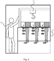
- These removable modules are accessible from above on one horizontal plane for the automation system to lift them from their operating position and replace them with spare module. Also, as shown in Fig. 2 this also facilitates access via human controlled manipulation.
- the complexity of an automation system is reduced, because a single portal crane with three degrees of freedom can be used first to drive to selected coordinates on the horizontal plane and then performing the lifting operation in the third (vertical) direction.
- the automation system weight handling requirements are also reduced, because the load center of gravity is always below the manipulator, thereby avoiding torque.
- FIG. 1 the replaceable modules are shown as separate boxes/modules, each one containing auxiliaries of one switching device. However, the boxes/modules can be merged to form one bigger box/module for all three phases or one bigger box/module for both circuit breaker and disconnector. The primary parts of these devices, if designed withdrawable, can be attached to the box/module as well to form one bigger and heavier removable module.
- Fig. 1 The design of the switchgear or control gear of Fig. 1 is shown with phases separated and single pole circuit breaker units. Rearrangement of state-of-art switchgear and controlgear design, with three phase switching devices is also possible.
- the disconnector switch in Fig.1 is shown as a linear movement type, but this also can be a disconnector switch with rotational movement.
- the removable module of the circuit breaker shown in Fig.1 includes the control electronics and auxiliaries and allows a simple electrical plug and socket connection to the circuit breaker drive.
- the module can also include parts of the CB drive, and then the interface to the CB pole can be a removable mechanical connection transferring mechanical energy from the drive to the CB moving contact.
- the removable module can comprise the complete circuit breaker single pole unit (the pole including drive and auxiliaries). For that purpose it is possible to use a rotational circuit breaker pole.
- the vacuum interrupter located in the central axis of the pole is then used for current interruption, while rotation of the pole around the central axis serves for connection, disconnection and earthing as a three position disconnector switch.
- Fig. 2 shows a detailed example of a switchgear or control gear designed specifically for human operation, where for ease of reference the following features shown are listed:
- the switchgear or control gear has been equipped with a manually operated lifting system.
- the primary circuit can include other components and devices not described in Fig.1 , such as earthing switch, voltage indication, surge arrestors, Ultra Fast Earthing Switch (UFES), IS-limiters (as invented by ABB Calor Emag in 1955), contactors, load-break switches, fuses.
- UFES Ultra Fast Earthing Switch
Landscapes
- Engineering & Computer Science (AREA)
- Power Engineering (AREA)
- Gas-Insulated Switchgears (AREA)
- Driving Mechanisms And Operating Circuits Of Arc-Extinguishing High-Tension Switches (AREA)
Claims (30)
- Schaltanlage oder Steuergerät, umfassend:- mindestens ein erstes Fach (1, 5, 9);- eine Mehrzahl von entfernbarer Modulen (6, 7);- eine Mehrzahl von Hauptschaltgeräte- oder Steuergerätekomponenten; und- eine Mehrzahl von Hilfsschaltgeräte- oder Betriebsgerätekomponenten;
wobei die Mehrzahl von Hauptschaltgeräte- oder Steuergerätekomponenten mindestens ein Haupt-Sammelschienensystem (2), mindestens einen Dreistellungs-Linear- oder Drehbewegungs-Trennschalter (3), mindestens einen Leistungsschalter (4) und mindestens einen Kabelanschluss umfasst;
wobei die Mehrzahl von Hilfsschaltgeräte- oder Betriebsgerätekomponenten mindestens einen Trennerantrieb und mindestens einen Leistungsschalterantrieb umfasst;
wobei die mehreren entfernbaren Module so konfiguriert sind, dass sie horizontal innerhalb des mindestens einen ersten Fachs an mehreren horizontalen Stellen montierbar sind;
wobei die mehreren Hauptschaltgeräte- oder Steuergerätekomponenten so konfiguriert sind, dass sie in dem mindestens einen ersten Fach untergebracht sind; wobei die mehreren Hilfsschaltgeräte- oder Betriebsgerätekomponenten in den mehreren entfernbaren Modulen untergebracht oder mit diesen verbunden sind wobei jedes der entfernbaren Module so konfiguriert ist, dass es vertikal aus seiner horizontalen Lage bewegt werden kann; und
wobei die Bewegung eines entfernbaren Moduls aus seiner horizontalen Lage, wobei die Bewegung eine vertikale Bewegung umfasst, die so konfiguriert ist, dass sie die eine oder mehrere Hilfskomponenten bewegt, die in diesem entfernbaren Modul untergebracht oder diesem zugeordnet sind. - Schaltanlage oder Steuergerät nach Anspruch 1, wobei die Schaltanlage oder das Steuergerät ein automatisches Wartungssystem umfasst, das sich innerhalb des mindestens einen ersten Fachs befindet, und wobei das automatische Wartungssystem so konfiguriert ist, dass es jedes der mehreren entfernbaren Module bewegt.
- Schaltanlage oder Steuergerät nach Anspruch 1, wobei jedes der entfernbaren Module so konfiguriert ist, dass es aus dem mindestens einen ersten Fach entfernt werden kann, und wobei das Entfernen eines entfernbaren Moduls aus dem mindestens einen ersten Fach die Bewegung des entfernbaren Moduls umfasst, und wobei das Entfernen des entfernbaren Moduls so konfiguriert ist, dass die eine oder die mehreren Hilfskomponenten, die in diesem herausnehmbaren Modul untergebracht oder diesem zugeordnet sind, aus dem mindestens einen ersten Fach entfernt werden.
- Schaltanlage oder Steuergerät nach Anspruch 3, wobei die Schaltanlage oder das Steuergerät ein manuell betätigtes Hebesystem umfasst, das so konfiguriert ist, dass es jedes der mehreren abnehmbaren Module bewegt und/oder entfernt.
- Schaltanlage oder Steuergerät nach einem der Ansprüche 1-4, wobei die mehreren Hilfsschaltgeräte oder Betriebsgerätekomponenten in mehrere logische Gruppen unterteilt sind und wobei die Komponenten in einer logischen Gruppe in demselben herausnehmbaren Modul untergebracht oder diesem zugeordnet sind.
- Schaltanlage oder Steuergerät nach Anspruch 5, wobei dem mindestens einen Trennerantrieb mindestens ein Hilfsgerät zugeordnet ist, und wobei ein oder mehrere Trennerantriebe des mindestens einen Trennerantriebs und ein oder mehrere zugeordnete Hilfsgeräte in einem ersten entfernbaren Modul untergebracht sind.
- Schaltanlage oder Steuergerät nach Anspruch 6, wobei drei Trennerantriebe und drei Sätze zugehöriger Hilfseinrichtungen im ersten entfernbaren Modul untergebracht sind.
- Schaltanlage oder Steuergerät nach Anspruch 6, wobei drei Trennerantriebe und drei Sätze zugehöriger Hilfseinrichtungen in drei verschiedenen entfernbaren Modulen untergebracht sind, von denen eines das erste herausnehmbare Modul ist.
- Schaltanlage oder Steuergerät nach einem der Ansprüche 6-8, wobei ein oder mehrere Dreistellungs-Linear- oder Drehbewegungs-Trennschalter des mindestens einen Dreistellungs-Linear- oder Drehbewegungs-Trennschalters in dem ersten entfernbaren Modul untergebracht oder diesem zugeordnet sind.
- Schaltanlage oder Steuergerät nach Anspruch 9, wobei 3 Dreistellungs-Linear- oder Drehbewegungs-Trennschalter in dem ersten entfernbaren Modul untergebracht oder diesem zugeordnet sind.
- Schaltanlage oder Steuergerät nach Anspruch 9 wenn von Anspruch 8 abhängig, wobei 3 lineare oder rotatorische Bewegungstrennschalter mit drei Positionen in den drei verschiedenen entfernbaren Modulen untergebracht oder diesen zugeordnet sind.
- Schaltanlage oder Steuergerät nach einem der Ansprüche 5-11, wobei dem mindestens einen Leistungsschalterantrieb mindestens ein Hilfsgerät zugeordnet ist, und wobei ein oder mehrere Leistungsschalterantriebe des mindestens einen Leistungsschalterantriebs und ein oder mehrere zugeordnete Hilfsgeräte in einem zweiten entfernbaren Modul untergebracht oder diesem zugeordnet sind.
- Schaltanlage oder Steuergerät nach Anspruch 12, wobei ein für alle drei Phasen gemeinsamer Leistungsschalterantrieb und ein für alle drei Phasen gemeinsamer Satz zugehöriger Hilfseinrichtungen in dem zweiten entfernbaren Modul untergebracht oder diesem zugeordnet sind.
- Schaltanlage oder Steuergerät nach Anspruch 12, wobei drei Leistungsschalterantriebe und drei Sätze zugehöriger Hilfseinrichtungen in dem zweiten entfernbaren Modul untergebracht oder diesem zugeordnet sind.
- Schaltanlage oder Steuergerät nach Anspruch 12, wobei drei Leistungsschalterantriebe und drei Sätze zugehöriger Hilfseinrichtungen in drei verschiedenen entfernbaren Modulen untergebracht oder diesen zugeordnet sind, von denen eines das zweite herausnehmbare Modul ist.
- Schaltanlage oder Steuergerät nach einem der Ansprüche 12-15, wobei ein oder mehrere Leistungsschalter des mindestens einen Leistungsschalters in dem zweiten entfernbaren Modul untergebracht oder diesem zugeordnet sind.
- Schaltanlage oder Steuergerät nach Anspruch 16, wobei drei Leistungsschalter in dem zweiten entfernbaren Modul untergebracht oder diesem zugeordnet sind.
- Schaltanlage oder Steuergerät nach Anspruch 16 wenn von Anspruch 14 abhängig, wobei drei Leistungsschalter in den drei verschiedenen entfernbaren Modulen untergebracht oder diesen zugeordnet sind.
- Schaltanlage oder Steuergerät nach einem der Ansprüche 1-18, wobei das mindestens eine erste Fach lichtbogenfest ist.
- Schaltanlage oder Steuergerät nach einem der Ansprüche 1-19, wobei jedes entfernbare Modul des mindestens einen entfernbaren Moduls eine Steckverbindung zu Versorgungs- und Signalsammelschaltungen umfasst, die so konfiguriert ist, dass sie eine Kommunikation und elektrische Verbindung mit mindestens einer Komponente außerhalb des entfernbaren Moduls ermöglicht.
- Schaltanlage oder Steuergerät nach Anspruch 20, wobei eine Steckverbindung der mindestens einen Steckverbindung zur elektrischen Verbindung zwischen einem Leistungsschalterantrieb des mindestens einen Leistungsschalterantriebs und einem Leistungsschalter des mindestens einen Leistungsschalters ausgebildet ist.
- Schaltanlage oder Steuergerät nach einem der Ansprüche 1 bis 21, wobei das mindestens eine erste Fach ein Kabelanschlussfach (5) umfasst, in dem der mindestens eine Kabelanschluss untergebracht ist; und wobei das mindestens eine Hauptsammelschienensystem, der mindestens eine lineare oder rotatorische Trennschalter mit drei Positionen und der mindestens eine Leistungsschalter nicht in dem Kabelanschlussfach untergebracht sind.
- Schaltanlage oder Steuergerät nach Anspruch 22, wobei mindestens eine Buchse (10) einen Teil der Verbindung zwischen dem mindestens einen Kabelanschluss und dem mindestens einen Leistungsschalter bildet, und wobei die mindestens eine Buchse Strom- und Spannungssensoren umfasst.
- Schaltanlage oder Steuergerät nach einem der Ansprüche 22-23, wobei das Kabelanschlussfach mindestens eine Tür oder einen abnehmbaren Wandabschnitt aufweist.
- Schaltanlage oder Steuergerät nach einem der Ansprüche 22-24, wobei eine Trennwand des Kabelanschlussfachs eine lichtbogensichere Trennung ist, die den Zugang eines Benutzers zum Kabelanschlussfach ermöglicht, wenn mindestens eine Komponente außerhalb des Kabelanschlussfachs, aber innerhalb des mindestens einen ersten Fachs in Betrieb ist.
- Schaltanlage oder Steuergerät nach einem der Ansprüche 22-25, wobei das mindestens eine erste Fach zusätzlich zum Kabelanschlussfach ein erstes Fach (9) und ein zweites Fach umfasst; und wobei das mindestens eine Hauptsammelschienensystem, der mindestens eine Trennschalter mit drei Positionen oder Drehbewegungen und der mindestens eine Leistungsschalter im zweiten Fach untergebracht sind.
- Schaltanlage oder Steuergerät nach Anspruch 26, wobei das erste Fach mindestens eine Tür oder einen abnehmbaren Wandabschnitt aufweist.
- Schaltanlage oder Steuergerät nach einem der Ansprüche 26-27, wobei mindestens eine Trennwand des ersten Fachs (9) eine lichtbogensichere Trennung ist, die den Zugang eines Benutzers zu dem ersten Fach des mindestens einen ersten Fachs ermöglicht, wenn mindestens eine Komponente außerhalb des ersten Fachs des mindestens einen ersten Fachs, aber innerhalb des mindestens einen ersten Fachs in Betrieb ist.
- Schaltanlage oder Steuergerät nach einem der Ansprüche 1-28, wobei ein entfernbares Modul, in dem Leistungsschalter-Steuerelektronik und Hilfsgeräte untergebracht oder zugeordnet sind, auch mindestens einen Teil eines Leistungsschalter-Antriebs beherbergt oder zugeordnet ist, und wobei eine Schnittstelle zu einem Leistungsschalterpol eine abnehmbare mechanische Verbindung umfasst, die so konfiguriert ist, dass sie mechanische Energie vom Leistungsschalter-Antrieb auf einen beweglichen Kontakt des Leistungsschalters überträgt.
- Schaltanlage oder Steuergerät nach Anspruch 29, wobei eine Leistungsschalter-Einzelpoleinheit in dem herausnehmbaren Modul untergebracht oder diesem zugeordnet ist, wobei die Leistungsschalter-Einzelpoleinheit einen drehbaren Leistungsschalterpol verwendet, wobei ein in einer Mittelachse des Pols angeordneter Vakuumunterbrecher als Hauptstromschalteinrichtung dient, während die Drehung des Pols um die Mittelachse so konfiguriert ist, dass sie als Dreistellungs-Trennschalter zum Verbinden, Trennen und Erden wirkt.
Priority Applications (4)
| Application Number | Priority Date | Filing Date | Title |
|---|---|---|---|
| EP18214235.6A EP3671992B1 (de) | 2018-12-19 | 2018-12-19 | Schaltanlage |
| ES18214235T ES2887257T3 (es) | 2018-12-19 | 2018-12-19 | Aparato de conmutación o aparato de control |
| CN201911312462.6A CN111342385B (zh) | 2018-12-19 | 2019-12-18 | 开关装置或控制装置 |
| US16/720,018 US11139642B2 (en) | 2018-12-19 | 2019-12-19 | Switchgear or control gear |
Applications Claiming Priority (1)
| Application Number | Priority Date | Filing Date | Title |
|---|---|---|---|
| EP18214235.6A EP3671992B1 (de) | 2018-12-19 | 2018-12-19 | Schaltanlage |
Publications (2)
| Publication Number | Publication Date |
|---|---|
| EP3671992A1 EP3671992A1 (de) | 2020-06-24 |
| EP3671992B1 true EP3671992B1 (de) | 2021-06-16 |
Family
ID=64755144
Family Applications (1)
| Application Number | Title | Priority Date | Filing Date |
|---|---|---|---|
| EP18214235.6A Active EP3671992B1 (de) | 2018-12-19 | 2018-12-19 | Schaltanlage |
Country Status (4)
| Country | Link |
|---|---|
| US (1) | US11139642B2 (de) |
| EP (1) | EP3671992B1 (de) |
| CN (1) | CN111342385B (de) |
| ES (1) | ES2887257T3 (de) |
Families Citing this family (4)
| Publication number | Priority date | Publication date | Assignee | Title |
|---|---|---|---|---|
| EP3671986B1 (de) * | 2018-12-19 | 2025-05-14 | ABB Schweiz AG | Schaltanlage |
| EP3671988A1 (de) * | 2018-12-19 | 2020-06-24 | ABB Schweiz AG | Hermetischgasdichte schaltanlage mit einem einzelnes fach für leistungsschalter, trennschalter mit dreipositionen und hauptbusschiene. |
| EP3671989B1 (de) * | 2018-12-19 | 2025-08-13 | ABB Schweiz AG | Dreiphasen-schaltanlage mit einphasiger ausrüstung in einem gehäuse |
| EP4089700A1 (de) * | 2021-05-14 | 2022-11-16 | ABB Schweiz AG | Trennschalter mit drei positionen |
Family Cites Families (13)
| Publication number | Priority date | Publication date | Assignee | Title |
|---|---|---|---|---|
| CN2701132Y (zh) * | 2004-05-26 | 2005-05-18 | 镇江龙源电器有限公司 | 户内高压复合绝缘金属封闭开关设备 |
| DE102009036590B3 (de) * | 2009-08-07 | 2011-03-31 | Abb Technology Ag | Gasisolierte Hochspannungsschaltanlage |
| EP2346126B1 (de) | 2010-01-18 | 2018-07-04 | ABB Schweiz AG | Luftisolierte Mittelspannungsschaltanlage |
| DE102010063130A1 (de) * | 2010-12-15 | 2012-06-21 | Abb Technology Ag | Schaltschrank zum Betreiben einer Mittel- oder Hochspannungsschaltanlage |
| JP5602977B1 (ja) * | 2013-02-13 | 2014-10-08 | 三菱電機株式会社 | ガス絶縁スイッチギヤ |
| CN104868394B (zh) * | 2015-05-15 | 2018-12-04 | 厦门柏瑞科电气有限公司 | 一种侧装中置开关柜 |
| EP3136414B1 (de) * | 2015-08-31 | 2019-06-26 | ABB Schweiz AG | Gasisolierte mittelspannungsschaltanlage mit einer schutzschalterpolteilanordnung |
| CN105680358B (zh) * | 2016-03-21 | 2018-06-29 | 南阳市鑫特电气有限公司 | 一种旋转抽出式高压真空断路器 |
| CN106601543A (zh) * | 2016-08-13 | 2017-04-26 | 信尔德科技有限公司 | 高压真空断路器 |
| EP3422502B1 (de) | 2017-06-28 | 2021-04-07 | ABB Schweiz AG | Unterstation für mittel- oder hochspannung mit schaltgerät oder steuergerät mit unbemannter operation und wartung |
| EP3422501B1 (de) | 2017-06-28 | 2021-04-28 | ABB Schweiz AG | Robot für unbemannten betrieb und wartung in einem mittel- oder hochspannungsgehäuse |
| EP3422503A1 (de) | 2017-06-28 | 2019-01-02 | ABB Schweiz AG | Ein interner roboter-manipulator für unbemannte betriebs- und wartungsarbeiten bei ausfahbarer leistungsschaltern und ein verfahren zum betreiben des roboter-manipulators |
| EP3421190B1 (de) | 2017-06-28 | 2022-05-04 | ABB Schweiz AG | Schaltgerät mit unbemannter bedienung und wartung sowie verfahren zum betrieb davon |
-
2018
- 2018-12-19 EP EP18214235.6A patent/EP3671992B1/de active Active
- 2018-12-19 ES ES18214235T patent/ES2887257T3/es active Active
-
2019
- 2019-12-18 CN CN201911312462.6A patent/CN111342385B/zh active Active
- 2019-12-19 US US16/720,018 patent/US11139642B2/en active Active
Also Published As
| Publication number | Publication date |
|---|---|
| EP3671992A1 (de) | 2020-06-24 |
| US20200203935A1 (en) | 2020-06-25 |
| ES2887257T3 (es) | 2021-12-22 |
| CN111342385A (zh) | 2020-06-26 |
| US11139642B2 (en) | 2021-10-05 |
| CN111342385B (zh) | 2022-03-04 |
Similar Documents
| Publication | Publication Date | Title |
|---|---|---|
| US11139642B2 (en) | Switchgear or control gear | |
| US11682885B2 (en) | Switchgear | |
| EP1218995B1 (de) | Gasisolierte schaltanlage | |
| US11637414B2 (en) | Three phase switchgear using single phase equipment in single casing | |
| EP2405544A2 (de) | Schaltanordnung für Doppelsammelschienen Auswahl | |
| JP5791832B2 (ja) | ガス絶縁スイッチギヤ | |
| US11005240B2 (en) | Three phase switchgear or control gear | |
| KR101203912B1 (ko) | 스위치 기어 | |
| US20100195273A1 (en) | Vacuum insulated switchgear | |
| CN109687334A (zh) | 一种船用中压配电装置 | |
| US7310220B2 (en) | High voltage outdoor substation | |
| US11670919B2 (en) | Three phase switchgear or control gear | |
| JP2014096914A (ja) | スイッチギヤまたはスイッチギヤ内の遮断器交換方法 | |
| CZ11978U1 (cs) | Dvousystémová kobková rozvodna | |
| GB2175449A (en) | Flameproof/modular switchgear | |
| HK1159866A (zh) | 开关装置 |
Legal Events
| Date | Code | Title | Description |
|---|---|---|---|
| PUAI | Public reference made under article 153(3) epc to a published international application that has entered the european phase |
Free format text: ORIGINAL CODE: 0009012 |
|
| STAA | Information on the status of an ep patent application or granted ep patent |
Free format text: STATUS: THE APPLICATION HAS BEEN PUBLISHED |
|
| AK | Designated contracting states |
Kind code of ref document: A1 Designated state(s): AL AT BE BG CH CY CZ DE DK EE ES FI FR GB GR HR HU IE IS IT LI LT LU LV MC MK MT NL NO PL PT RO RS SE SI SK SM TR |
|
| AX | Request for extension of the european patent |
Extension state: BA ME |
|
| STAA | Information on the status of an ep patent application or granted ep patent |
Free format text: STATUS: REQUEST FOR EXAMINATION WAS MADE |
|
| 17P | Request for examination filed |
Effective date: 20201125 |
|
| RBV | Designated contracting states (corrected) |
Designated state(s): AL AT BE BG CH CY CZ DE DK EE ES FI FR GB GR HR HU IE IS IT LI LT LU LV MC MK MT NL NO PL PT RO RS SE SI SK SM TR |
|
| GRAP | Despatch of communication of intention to grant a patent |
Free format text: ORIGINAL CODE: EPIDOSNIGR1 |
|
| STAA | Information on the status of an ep patent application or granted ep patent |
Free format text: STATUS: GRANT OF PATENT IS INTENDED |
|
| INTG | Intention to grant announced |
Effective date: 20210113 |
|
| GRAS | Grant fee paid |
Free format text: ORIGINAL CODE: EPIDOSNIGR3 |
|
| GRAA | (expected) grant |
Free format text: ORIGINAL CODE: 0009210 |
|
| STAA | Information on the status of an ep patent application or granted ep patent |
Free format text: STATUS: THE PATENT HAS BEEN GRANTED |
|
| AK | Designated contracting states |
Kind code of ref document: B1 Designated state(s): AL AT BE BG CH CY CZ DE DK EE ES FI FR GB GR HR HU IE IS IT LI LT LU LV MC MK MT NL NO PL PT RO RS SE SI SK SM TR |
|
| RAP3 | Party data changed (applicant data changed or rights of an application transferred) |
Owner name: ABB SCHWEIZ AG |
|
| REG | Reference to a national code |
Ref country code: GB Ref legal event code: FG4D |
|
| REG | Reference to a national code |
Ref country code: CH Ref legal event code: EP |
|
| REG | Reference to a national code |
Ref country code: DE Ref legal event code: R096 Ref document number: 602018018627 Country of ref document: DE |
|
| REG | Reference to a national code |
Ref country code: AT Ref legal event code: REF Ref document number: 1403122 Country of ref document: AT Kind code of ref document: T Effective date: 20210715 |
|
| REG | Reference to a national code |
Ref country code: IE Ref legal event code: FG4D |
|
| REG | Reference to a national code |
Ref country code: LT Ref legal event code: MG9D |
|
| PG25 | Lapsed in a contracting state [announced via postgrant information from national office to epo] |
Ref country code: BG Free format text: LAPSE BECAUSE OF FAILURE TO SUBMIT A TRANSLATION OF THE DESCRIPTION OR TO PAY THE FEE WITHIN THE PRESCRIBED TIME-LIMIT Effective date: 20210916 Ref country code: FI Free format text: LAPSE BECAUSE OF FAILURE TO SUBMIT A TRANSLATION OF THE DESCRIPTION OR TO PAY THE FEE WITHIN THE PRESCRIBED TIME-LIMIT Effective date: 20210616 Ref country code: HR Free format text: LAPSE BECAUSE OF FAILURE TO SUBMIT A TRANSLATION OF THE DESCRIPTION OR TO PAY THE FEE WITHIN THE PRESCRIBED TIME-LIMIT Effective date: 20210616 Ref country code: LT Free format text: LAPSE BECAUSE OF FAILURE TO SUBMIT A TRANSLATION OF THE DESCRIPTION OR TO PAY THE FEE WITHIN THE PRESCRIBED TIME-LIMIT Effective date: 20210616 |
|
| REG | Reference to a national code |
Ref country code: AT Ref legal event code: MK05 Ref document number: 1403122 Country of ref document: AT Kind code of ref document: T Effective date: 20210616 |
|
| REG | Reference to a national code |
Ref country code: NL Ref legal event code: MP Effective date: 20210616 |
|
| PG25 | Lapsed in a contracting state [announced via postgrant information from national office to epo] |
Ref country code: GR Free format text: LAPSE BECAUSE OF FAILURE TO SUBMIT A TRANSLATION OF THE DESCRIPTION OR TO PAY THE FEE WITHIN THE PRESCRIBED TIME-LIMIT Effective date: 20210917 Ref country code: LV Free format text: LAPSE BECAUSE OF FAILURE TO SUBMIT A TRANSLATION OF THE DESCRIPTION OR TO PAY THE FEE WITHIN THE PRESCRIBED TIME-LIMIT Effective date: 20210616 Ref country code: NO Free format text: LAPSE BECAUSE OF FAILURE TO SUBMIT A TRANSLATION OF THE DESCRIPTION OR TO PAY THE FEE WITHIN THE PRESCRIBED TIME-LIMIT Effective date: 20210916 Ref country code: RS Free format text: LAPSE BECAUSE OF FAILURE TO SUBMIT A TRANSLATION OF THE DESCRIPTION OR TO PAY THE FEE WITHIN THE PRESCRIBED TIME-LIMIT Effective date: 20210616 Ref country code: SE Free format text: LAPSE BECAUSE OF FAILURE TO SUBMIT A TRANSLATION OF THE DESCRIPTION OR TO PAY THE FEE WITHIN THE PRESCRIBED TIME-LIMIT Effective date: 20210616 |
|
| REG | Reference to a national code |
Ref country code: ES Ref legal event code: FG2A Ref document number: 2887257 Country of ref document: ES Kind code of ref document: T3 Effective date: 20211222 |
|
| PG25 | Lapsed in a contracting state [announced via postgrant information from national office to epo] |
Ref country code: SK Free format text: LAPSE BECAUSE OF FAILURE TO SUBMIT A TRANSLATION OF THE DESCRIPTION OR TO PAY THE FEE WITHIN THE PRESCRIBED TIME-LIMIT Effective date: 20210616 Ref country code: SM Free format text: LAPSE BECAUSE OF FAILURE TO SUBMIT A TRANSLATION OF THE DESCRIPTION OR TO PAY THE FEE WITHIN THE PRESCRIBED TIME-LIMIT Effective date: 20210616 Ref country code: EE Free format text: LAPSE BECAUSE OF FAILURE TO SUBMIT A TRANSLATION OF THE DESCRIPTION OR TO PAY THE FEE WITHIN THE PRESCRIBED TIME-LIMIT Effective date: 20210616 Ref country code: CZ Free format text: LAPSE BECAUSE OF FAILURE TO SUBMIT A TRANSLATION OF THE DESCRIPTION OR TO PAY THE FEE WITHIN THE PRESCRIBED TIME-LIMIT Effective date: 20210616 Ref country code: AT Free format text: LAPSE BECAUSE OF FAILURE TO SUBMIT A TRANSLATION OF THE DESCRIPTION OR TO PAY THE FEE WITHIN THE PRESCRIBED TIME-LIMIT Effective date: 20210616 Ref country code: PT Free format text: LAPSE BECAUSE OF FAILURE TO SUBMIT A TRANSLATION OF THE DESCRIPTION OR TO PAY THE FEE WITHIN THE PRESCRIBED TIME-LIMIT Effective date: 20211018 Ref country code: RO Free format text: LAPSE BECAUSE OF FAILURE TO SUBMIT A TRANSLATION OF THE DESCRIPTION OR TO PAY THE FEE WITHIN THE PRESCRIBED TIME-LIMIT Effective date: 20210616 Ref country code: NL Free format text: LAPSE BECAUSE OF FAILURE TO SUBMIT A TRANSLATION OF THE DESCRIPTION OR TO PAY THE FEE WITHIN THE PRESCRIBED TIME-LIMIT Effective date: 20210616 |
|
| PG25 | Lapsed in a contracting state [announced via postgrant information from national office to epo] |
Ref country code: PL Free format text: LAPSE BECAUSE OF FAILURE TO SUBMIT A TRANSLATION OF THE DESCRIPTION OR TO PAY THE FEE WITHIN THE PRESCRIBED TIME-LIMIT Effective date: 20210616 |
|
| REG | Reference to a national code |
Ref country code: DE Ref legal event code: R097 Ref document number: 602018018627 Country of ref document: DE |
|
| PLBE | No opposition filed within time limit |
Free format text: ORIGINAL CODE: 0009261 |
|
| STAA | Information on the status of an ep patent application or granted ep patent |
Free format text: STATUS: NO OPPOSITION FILED WITHIN TIME LIMIT |
|
| PG25 | Lapsed in a contracting state [announced via postgrant information from national office to epo] |
Ref country code: DK Free format text: LAPSE BECAUSE OF FAILURE TO SUBMIT A TRANSLATION OF THE DESCRIPTION OR TO PAY THE FEE WITHIN THE PRESCRIBED TIME-LIMIT Effective date: 20210616 |
|
| 26N | No opposition filed |
Effective date: 20220317 |
|
| PG25 | Lapsed in a contracting state [announced via postgrant information from national office to epo] |
Ref country code: AL Free format text: LAPSE BECAUSE OF FAILURE TO SUBMIT A TRANSLATION OF THE DESCRIPTION OR TO PAY THE FEE WITHIN THE PRESCRIBED TIME-LIMIT Effective date: 20210616 |
|
| PG25 | Lapsed in a contracting state [announced via postgrant information from national office to epo] |
Ref country code: MC Free format text: LAPSE BECAUSE OF FAILURE TO SUBMIT A TRANSLATION OF THE DESCRIPTION OR TO PAY THE FEE WITHIN THE PRESCRIBED TIME-LIMIT Effective date: 20210616 |
|
| REG | Reference to a national code |
Ref country code: CH Ref legal event code: PL |
|
| REG | Reference to a national code |
Ref country code: BE Ref legal event code: MM Effective date: 20211231 |
|
| PG25 | Lapsed in a contracting state [announced via postgrant information from national office to epo] |
Ref country code: LU Free format text: LAPSE BECAUSE OF NON-PAYMENT OF DUE FEES Effective date: 20211219 Ref country code: IE Free format text: LAPSE BECAUSE OF NON-PAYMENT OF DUE FEES Effective date: 20211219 |
|
| PG25 | Lapsed in a contracting state [announced via postgrant information from national office to epo] |
Ref country code: BE Free format text: LAPSE BECAUSE OF NON-PAYMENT OF DUE FEES Effective date: 20211231 |
|
| PG25 | Lapsed in a contracting state [announced via postgrant information from national office to epo] |
Ref country code: LI Free format text: LAPSE BECAUSE OF NON-PAYMENT OF DUE FEES Effective date: 20211231 Ref country code: CH Free format text: LAPSE BECAUSE OF NON-PAYMENT OF DUE FEES Effective date: 20211231 |
|
| PG25 | Lapsed in a contracting state [announced via postgrant information from national office to epo] |
Ref country code: CY Free format text: LAPSE BECAUSE OF FAILURE TO SUBMIT A TRANSLATION OF THE DESCRIPTION OR TO PAY THE FEE WITHIN THE PRESCRIBED TIME-LIMIT Effective date: 20210616 |
|
| PG25 | Lapsed in a contracting state [announced via postgrant information from national office to epo] |
Ref country code: HU Free format text: LAPSE BECAUSE OF FAILURE TO SUBMIT A TRANSLATION OF THE DESCRIPTION OR TO PAY THE FEE WITHIN THE PRESCRIBED TIME-LIMIT; INVALID AB INITIO Effective date: 20181219 |
|
| GBPC | Gb: european patent ceased through non-payment of renewal fee |
Effective date: 20221219 |
|
| PG25 | Lapsed in a contracting state [announced via postgrant information from national office to epo] |
Ref country code: GB Free format text: LAPSE BECAUSE OF NON-PAYMENT OF DUE FEES Effective date: 20221219 |
|
| PG25 | Lapsed in a contracting state [announced via postgrant information from national office to epo] |
Ref country code: MK Free format text: LAPSE BECAUSE OF FAILURE TO SUBMIT A TRANSLATION OF THE DESCRIPTION OR TO PAY THE FEE WITHIN THE PRESCRIBED TIME-LIMIT Effective date: 20210616 |
|
| PG25 | Lapsed in a contracting state [announced via postgrant information from national office to epo] |
Ref country code: TR Free format text: LAPSE BECAUSE OF FAILURE TO SUBMIT A TRANSLATION OF THE DESCRIPTION OR TO PAY THE FEE WITHIN THE PRESCRIBED TIME-LIMIT Effective date: 20210616 |
|
| PG25 | Lapsed in a contracting state [announced via postgrant information from national office to epo] |
Ref country code: MT Free format text: LAPSE BECAUSE OF FAILURE TO SUBMIT A TRANSLATION OF THE DESCRIPTION OR TO PAY THE FEE WITHIN THE PRESCRIBED TIME-LIMIT Effective date: 20210616 |
|
| PGFP | Annual fee paid to national office [announced via postgrant information from national office to epo] |
Ref country code: DE Payment date: 20251211 Year of fee payment: 8 |
|
| PGFP | Annual fee paid to national office [announced via postgrant information from national office to epo] |
Ref country code: IT Payment date: 20251223 Year of fee payment: 8 |
|
| PGFP | Annual fee paid to national office [announced via postgrant information from national office to epo] |
Ref country code: FR Payment date: 20251229 Year of fee payment: 8 |
|
| PGFP | Annual fee paid to national office [announced via postgrant information from national office to epo] |
Ref country code: ES Payment date: 20260130 Year of fee payment: 8 |