EP3671968A2 - Electrical connector housing, electrical connector and electrical connector assembly - Google Patents
Electrical connector housing, electrical connector and electrical connector assembly Download PDFInfo
- Publication number
- EP3671968A2 EP3671968A2 EP19216850.8A EP19216850A EP3671968A2 EP 3671968 A2 EP3671968 A2 EP 3671968A2 EP 19216850 A EP19216850 A EP 19216850A EP 3671968 A2 EP3671968 A2 EP 3671968A2
- Authority
- EP
- European Patent Office
- Prior art keywords
- electrical connector
- movable pin
- receiving portion
- elastic piece
- elastic
- Prior art date
- Legal status (The legal status is an assumption and is not a legal conclusion. Google has not performed a legal analysis and makes no representation as to the accuracy of the status listed.)
- Granted
Links
Images




Classifications
-
- H—ELECTRICITY
- H01—ELECTRIC ELEMENTS
- H01R—ELECTRICALLY-CONDUCTIVE CONNECTIONS; STRUCTURAL ASSOCIATIONS OF A PLURALITY OF MUTUALLY-INSULATED ELECTRICAL CONNECTING ELEMENTS; COUPLING DEVICES; CURRENT COLLECTORS
- H01R13/00—Details of coupling devices of the kinds covered by groups H01R12/70 or H01R24/00 - H01R33/00
- H01R13/02—Contact members
- H01R13/15—Pins, blades or sockets having separate spring member for producing or increasing contact pressure
-
- H—ELECTRICITY
- H01—ELECTRIC ELEMENTS
- H01R—ELECTRICALLY-CONDUCTIVE CONNECTIONS; STRUCTURAL ASSOCIATIONS OF A PLURALITY OF MUTUALLY-INSULATED ELECTRICAL CONNECTING ELEMENTS; COUPLING DEVICES; CURRENT COLLECTORS
- H01R13/00—Details of coupling devices of the kinds covered by groups H01R12/70 or H01R24/00 - H01R33/00
- H01R13/62—Means for facilitating engagement or disengagement of coupling parts or for holding them in engagement
- H01R13/629—Additional means for facilitating engagement or disengagement of coupling parts, e.g. aligning or guiding means, levers, gas pressure electrical locking indicators, manufacturing tolerances
-
- H—ELECTRICITY
- H01—ELECTRIC ELEMENTS
- H01R—ELECTRICALLY-CONDUCTIVE CONNECTIONS; STRUCTURAL ASSOCIATIONS OF A PLURALITY OF MUTUALLY-INSULATED ELECTRICAL CONNECTING ELEMENTS; COUPLING DEVICES; CURRENT COLLECTORS
- H01R12/00—Structural associations of a plurality of mutually-insulated electrical connecting elements, specially adapted for printed circuits, e.g. printed circuit boards [PCB], flat or ribbon cables, or like generally planar structures, e.g. terminal strips, terminal blocks; Coupling devices specially adapted for printed circuits, flat or ribbon cables, or like generally planar structures; Terminals specially adapted for contact with, or insertion into, printed circuits, flat or ribbon cables, or like generally planar structures
- H01R12/70—Coupling devices
- H01R12/71—Coupling devices for rigid printing circuits or like structures
- H01R12/712—Coupling devices for rigid printing circuits or like structures co-operating with the surface of the printed circuit or with a coupling device exclusively provided on the surface of the printed circuit
- H01R12/714—Coupling devices for rigid printing circuits or like structures co-operating with the surface of the printed circuit or with a coupling device exclusively provided on the surface of the printed circuit with contacts abutting directly the printed circuit; Button contacts therefore provided on the printed circuit
-
- H—ELECTRICITY
- H01—ELECTRIC ELEMENTS
- H01R—ELECTRICALLY-CONDUCTIVE CONNECTIONS; STRUCTURAL ASSOCIATIONS OF A PLURALITY OF MUTUALLY-INSULATED ELECTRICAL CONNECTING ELEMENTS; COUPLING DEVICES; CURRENT COLLECTORS
- H01R13/00—Details of coupling devices of the kinds covered by groups H01R12/70 or H01R24/00 - H01R33/00
- H01R13/02—Contact members
- H01R13/15—Pins, blades or sockets having separate spring member for producing or increasing contact pressure
- H01R13/187—Pins, blades or sockets having separate spring member for producing or increasing contact pressure with spring member in the socket
-
- H—ELECTRICITY
- H01—ELECTRIC ELEMENTS
- H01R—ELECTRICALLY-CONDUCTIVE CONNECTIONS; STRUCTURAL ASSOCIATIONS OF A PLURALITY OF MUTUALLY-INSULATED ELECTRICAL CONNECTING ELEMENTS; COUPLING DEVICES; CURRENT COLLECTORS
- H01R13/00—Details of coupling devices of the kinds covered by groups H01R12/70 or H01R24/00 - H01R33/00
- H01R13/02—Contact members
- H01R13/22—Contacts for co-operating by abutting
- H01R13/24—Contacts for co-operating by abutting resilient; resiliently-mounted
- H01R13/2407—Contacts for co-operating by abutting resilient; resiliently-mounted characterized by the resilient means
-
- H—ELECTRICITY
- H01—ELECTRIC ELEMENTS
- H01R—ELECTRICALLY-CONDUCTIVE CONNECTIONS; STRUCTURAL ASSOCIATIONS OF A PLURALITY OF MUTUALLY-INSULATED ELECTRICAL CONNECTING ELEMENTS; COUPLING DEVICES; CURRENT COLLECTORS
- H01R13/00—Details of coupling devices of the kinds covered by groups H01R12/70 or H01R24/00 - H01R33/00
- H01R13/02—Contact members
- H01R13/22—Contacts for co-operating by abutting
- H01R13/24—Contacts for co-operating by abutting resilient; resiliently-mounted
- H01R13/2407—Contacts for co-operating by abutting resilient; resiliently-mounted characterized by the resilient means
- H01R13/2421—Contacts for co-operating by abutting resilient; resiliently-mounted characterized by the resilient means using coil springs
-
- H—ELECTRICITY
- H01—ELECTRIC ELEMENTS
- H01R—ELECTRICALLY-CONDUCTIVE CONNECTIONS; STRUCTURAL ASSOCIATIONS OF A PLURALITY OF MUTUALLY-INSULATED ELECTRICAL CONNECTING ELEMENTS; COUPLING DEVICES; CURRENT COLLECTORS
- H01R13/00—Details of coupling devices of the kinds covered by groups H01R12/70 or H01R24/00 - H01R33/00
- H01R13/02—Contact members
- H01R13/22—Contacts for co-operating by abutting
- H01R13/24—Contacts for co-operating by abutting resilient; resiliently-mounted
- H01R13/245—Contacts for co-operating by abutting resilient; resiliently-mounted by stamped-out resilient contact arm
-
- H—ELECTRICITY
- H01—ELECTRIC ELEMENTS
- H01R—ELECTRICALLY-CONDUCTIVE CONNECTIONS; STRUCTURAL ASSOCIATIONS OF A PLURALITY OF MUTUALLY-INSULATED ELECTRICAL CONNECTING ELEMENTS; COUPLING DEVICES; CURRENT COLLECTORS
- H01R13/00—Details of coupling devices of the kinds covered by groups H01R12/70 or H01R24/00 - H01R33/00
- H01R13/40—Securing contact members in or to a base or case; Insulating of contact members
- H01R13/42—Securing in a demountable manner
- H01R13/422—Securing in resilient one-piece base or case, e.g. by friction; One-piece base or case formed with resilient locking means
- H01R13/4223—Securing in resilient one-piece base or case, e.g. by friction; One-piece base or case formed with resilient locking means comprising integral flexible contact retaining fingers
- H01R13/4226—Securing in resilient one-piece base or case, e.g. by friction; One-piece base or case formed with resilient locking means comprising integral flexible contact retaining fingers comprising two or more integral flexible retaining fingers acting on a single contact
-
- H—ELECTRICITY
- H01—ELECTRIC ELEMENTS
- H01R—ELECTRICALLY-CONDUCTIVE CONNECTIONS; STRUCTURAL ASSOCIATIONS OF A PLURALITY OF MUTUALLY-INSULATED ELECTRICAL CONNECTING ELEMENTS; COUPLING DEVICES; CURRENT COLLECTORS
- H01R13/00—Details of coupling devices of the kinds covered by groups H01R12/70 or H01R24/00 - H01R33/00
- H01R13/46—Bases; Cases
-
- H—ELECTRICITY
- H01—ELECTRIC ELEMENTS
- H01R—ELECTRICALLY-CONDUCTIVE CONNECTIONS; STRUCTURAL ASSOCIATIONS OF A PLURALITY OF MUTUALLY-INSULATED ELECTRICAL CONNECTING ELEMENTS; COUPLING DEVICES; CURRENT COLLECTORS
- H01R13/00—Details of coupling devices of the kinds covered by groups H01R12/70 or H01R24/00 - H01R33/00
- H01R13/62—Means for facilitating engagement or disengagement of coupling parts or for holding them in engagement
- H01R13/639—Additional means for holding or locking coupling parts together, after engagement, e.g. separate keylock, retainer strap
-
- H—ELECTRICITY
- H01—ELECTRIC ELEMENTS
- H01R—ELECTRICALLY-CONDUCTIVE CONNECTIONS; STRUCTURAL ASSOCIATIONS OF A PLURALITY OF MUTUALLY-INSULATED ELECTRICAL CONNECTING ELEMENTS; COUPLING DEVICES; CURRENT COLLECTORS
- H01R24/00—Two-part coupling devices, or either of their cooperating parts, characterised by their overall structure
- H01R24/38—Two-part coupling devices, or either of their cooperating parts, characterised by their overall structure having concentrically or coaxially arranged contacts
Definitions
- At least one embodiment of the present disclosure relates to an electrical connector, and more particularly, to an electrical connector housing capable of maintaining stably contact with a movable pin, an electrical connector including the electrical connector housing, and an electrical connector assembly including the electrical connector.
- Some existing electrical connectors generally comprises a structure of a movable pin which is placed in a receiving portion of a cylindrical electrical connector housing, a first end of the movable pin being located in the receiving portion and movably protruding out of the receiving portion against elasticity of a spring so as to be electrically connected to a connection terminal.
- the movable pin is generally kept in contact with the electrical connector housing by a slope at one end thereof.
- Such contact is not stable enough, particularly when there is a vibration or external force applied to the movable pin, which results in poor contact between the movable pin and the electrical connector housing, thereby generating high frequency resonance and current transient interruption.
- An object of the present disclosure is to solve at least one of the above and other problems and defects existing in the prior arts.
- an electrical connector comprising: an electrical connector housing comprising a body in which an receiving portion is formed; at least one movable pin, a part of which is movably located in the receiving portion; a first elastic piece located in the receiving portion, a first end of each movable pin movably protruding out of the receiving portion against elasticity of the first elastic piece; and at least one second elastic piece located between a side wall of the receiving portion and the movable pin and configured to be elastically abutted against an outer circumferential surface of the movable pin.
- the movable pin is adapted to be electrically connected to the electrical connector housing by the first elastic piece and the second elastic piece.
- the second elastic piece is an elastic arm integrally connected to the body.
- each of the elastic arms is formed as an arc-shaped structure protruding from an inner side surface of the electrical connector housing toward the movable pin to be in elastic contact with the movable pin.
- each of the elastic arms extends in an axial direction of the body.
- a plurality of elastic arms are distributed at equal intervals in a circumference direction of the body.
- the second elastic piece is a tube spring provided between a side wall of the electrical connector housing and the movable pin.
- the tube spring comprises at least one elastic sheet each extending axially from two opposite ends of the tube spring toward each other, and being formed as an arc-shaped or a V-shaped structure protruding toward the movable pin.
- the tube spring is provided with an open slot extending axially through the two opposite ends of the tube spring.
- the movable pin is rod-shaped, a second end of the movable pin opposite to the first end being inserted into the receiving portion of the electrical connector housing, and an outer diameter of the first end being smaller than that of the second end.
- the electrical connector further comprises at least one stopping portion engaged with the second end of the movable pin to prevent the movable pin from sliding out of the receiving portion.
- the stopping portion is a stopping elastic sheet integrally connected to the body and protruding radially inward.
- the stopping portion is a recess formed in the body.
- the first end of the receiving portion is provided with a flange protruding radially inward.
- first ends of two movable pins protrude out of opposite first and second ends of the receiving portion, , respectively and the first elastic piece is located between the two movable pins.
- the first end of one movable pin protrudes out of a first end of the receiving portion, and the first elastic piece is located between a second end of the movable pin opposite to the first end and a second end of the receiving portion which is closed and is formed with an extension portion extending away from the first end of the receiving portion.
- the electrical connector housing is formed by stamping.
- an electrical connector housing comprising: a body in which an receiving portion is formed; and at least one elastic arm integrally connected to the body and configured to be elastically abutted against an outer circumferential surface of a movable pin, a part of which is movably located in the receiving portion.
- each of the elastic arms is formed as an arc-shaped structure protruding from an inner side surface of the electrical connector housing toward the movable pin to be in elastic contact with the movable pin.
- each of the elastic arms extends in an axial direction of the body.
- a plurality of elastic arms are distributed at equal intervals in a circumference direction of the body.
- the electrical connector housing further comprises at least one stopping portion adapted to prevent the movable pin from sliding out of the receiving portion.
- the stopping portion is a stopping elastic sheet integrally connected to the body and protruding radially inward.
- the stopping portion is a recess formed in the body.
- the first end of the receiving portion is provided with a flange protruding radially inward.
- opposite first and second ends of the receiving portion are open.
- a first end of the receiving portion is open and a second end of the receiving portion opposite the first end is closed, the second end of the receiving portion being formed with an extension extending portion away from the first end of the receiving portion.
- the electrical connector housing is made by stamping.
- an electrical connector assembly comprising an electrical connector as described above; and a cylinder comprising: an outer conductive cylinder and an inner insulation cylinder provided in the outer conductive cylinder, the electrical connector being provided in the inner insulation cylinder and isolated from the outer conducting cylinder by the inner insulation cylinder.
- the electrical connector housing is provided with a positioning tab engaged with the inner insulation cylinder.
- the electrical connector assembly further comprises a mating connector including an insulation base and a connection terminal connected to the insulation base, the connection terminal extending partially into the outer conductive cylinder and electrically connected to the outer conductive cylinder.
- the electrical connector assembly further comprises a third elastic piece, two opposite ends of the third elastic piece being elastically abutted against the insulation base and the outer conductive barrel, respectively.
- the second elastic piece is provided between the side wall of the receiving portion and the movable pin, and is elastically abutted against the outer circumferential surface of the movable pin, so that the movable pin is electrically connected to the electrical connector housing by the first elastic piece and the second elastic piece, thereby improving the reliability of electrical contact.
- the mobile pin may be kept in electrical contact with the electrical connector housing by the first and the second elastic pieces even in the event of vibration or external force applied to the movable pin, thereby avoiding the occurrence of high frequency resonance and current transient interruption.
- an electrical connector comprising: an electrical connector housing comprising a body in which an receiving portion is formed; at least one movable pin, a part of which is movably located in the receiving portion; a first elastic piece located in the receiving portion, a first end of each movable pin movably protruding out of the receiving portion against elasticity of the first elastic piece; and at least one second elastic piece located between a side wall of the receiving portion and the movable pin and configured to be elastically abutted against an outer circumferential surface of the movable pin.
- the movable pin is adapted to be electrically connected to the electrical connector housing by the first elastic piece and the second elastic piece.
- an electrical connector housing comprising: a body in which an receiving portion is formed; and at least one elastic arm integrally connected to the body and configured to be elastically abutted against an outer circumferential surface of a movable pin, a part of which is movably located in the receiving portion.
- an electrical connector assembly comprising an electrical connector as described above; and a cylinder comprising: an outer conductive cylinder and an inner insulation cylinder provided in the outer conductive cylinder, the electrical connector being provided in the inner insulation cylinder and isolated from the outer conducting cylinder by the inner insulation cylinder.
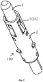
- Fig. 1 is a perspective schematic view illustrating an electrical connector according to an exemplary embodiment of the present disclosure
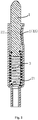
- Fig. 2 is a cross-sectional schematic view illustrating an electrical connector according to an exemplary embodiment of the present disclosure
- Fig. 3 is a perspective schematic view illustrating an electrical connector housing according to an exemplary embodiment of the present disclosure
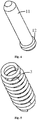
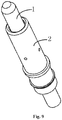
- Fig. 4 is a perspective schematic view illustrating a movable pin according to an exemplary embodiment of the present disclosure
- Fig. 5 is a perspective schematic view illustrating a first elastic piece according to an exemplary embodiment of the present disclosure.
- an electrical connector 100 comprises: a cylindrical electrical connector housing 2 comprising a body 21, one movable pin 1, a first elastic piece 3 and a plurality of second elastic pieces 4.
- a cylindrical receiving portion 22 is formed in the body 21, a part of the movable pin 1 is movably located in the receiving portion 22, and the first elastic piece 3 is located in the receiving portion 22.
- a first end 11 of the movable pin 1 movably protrudes out of the receiving portion 22 against elasticity of the first elastic piece 3.
- the plurality of second elastic pieces 4 are located between a side wall of the receiving portion 22 and the movable pin 1 and are configured to be elastically abutted against an outer circumferential surface of the movable pin 1, so that the movable pin 1 may be electrically connected to the electrical connector housing 2 by the first elastic piece 3 and the second elastic pieces 4.
- the plurality of second elastic pieces 4 comprises a plurality of elastic arms 4A integrally connected to the body 21 and are distributed at intervals in a circumferential direction of the receiving portion 22, so that the movable pin 1 may be kept in electrical contact with the electrical connector housing 2 by the first elastic piece 3 and the second elastic pieces 4 in the event of vibration or external force applied to the movable pin 1.
- each of the elastic arms 4A is formed as an arc-shaped structure protruding from the inner side surface of the electrical connector housing 2 toward the movable pin 1 to be in elastic contact with the movable pin 1, thereby making the movable pin 1 be in reliable electrical contact with the electrical connector housing 2.
- the first end 11 of one movable pin 1 protrudes out of a first end of the receiving portion 22 to be electrically connected to a first electronic component (e.g., a PCB board, not shown), and the first elastic piece 3 is located between a second end 12 of the movable pin 1 opposite to the first end 11 and a second end of the receiving portion 22 which is closed and is formed with an extension portion 27 extending away from the first end of the receiving portion 22 to be electrically connected to a second electronic component (e.g., a PCB board, not shown).
- a first electronic component e.g., a PCB board, not shown
- each of the elastic arms 4A extends in an axial direction of the body 21, thereby facilitating insertion of the movable pin 1 into the receiving portion 22 of the electrical connector housing 2. It is appreciated for those skilled in the art that in other embodiments of the present disclosure, the elastic arm 4A may also extend in a circumferential direction of the body 21, for example.
- the plurality of elastic arms 4A are distributed at regular intervals in the circumferential direction of the body 21, thereby making it easy for the movable pin 1 to be positioned at the center of the receiving portion 22 by the elastic force of the plurality of elastic arms 4A. That is, the axis of the movable pin 1 is coincided with the axis of the receiving portion 22.
- the movable pin 1 is rod-shaped, the first end 11 of the movable pin 1 protruding out of the receiving portion 22 of the electrical connector housing 2, the second end 12 of the movable pin 1 opposite to the first end 11 being inserted into the receiving portion 22 of the electrical connector housing 2, and an outer diameter of the first end 11 being smaller than that of the second end 12. That is, a step is provided between the first end 11 and the second end 12 of the movable pin 1 so that the movable pin 1 is held in the electrical connector housing 2 by the step.
- the electrical connector housing 2 further comprises at least one stopping portion 23 engaged with the second end 12 of the movable pin 1 to prevent the movable pin 1 from sliding out of the receiving portion 22.
- the stopping portion 23 comprises a stopping elastic sheet 23A integrally connected to the body 21 and radially protruding inward.
- a plurality of stopping elastic pieces 23A are distributed at regular intervals in the circumferential direction of the receiving portion 22, and the stopping elastic sheets 23A extend in the axial direction of the body 21.
- a connection between the stopping elastic sheet 23A and the body 21 is close to the first end of the receiving portion 22, and an end of the stopping elastic sheet 23A opposite to the connection with the body 21 is far away from the first end of the receiving portion 22, so that the stopping elastic sheet 23A is deformed by a force of the movable pin 1 to pass the movable pin 1 during the process of inserting the movable pin 1 into the receiving portion 22.
- the stopping elastic sheet 23A is restored by its elastic force, and may be interfered with the step between the first end 11 and the second end 12 of the movable pin 1, thereby preventing the movable pin 1 from slipping out of the receiving portion 22.
- the electrical connector housing 2 is formed as a single conductive member by stamping a single sheet of metal.
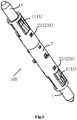
- Fig. 6 is a perspective schematic view illustrating an electrical connector according to another exemplary embodiment of the present disclosure
- Fig. 7 is a cross-sectional schematic view illustrating the electrical connector shown in fig. 6 .
- the electrical connector 100 comprises two movable pins 1, first ends 11 of the two movable pins 1 protruding out of the opposite first and second ends of the receiving portion 22 to be electrically connected to the first electronic component (e.g., a PCB board, not shown) and the second electronic component (e.g., a PCB board, not shown), respectively.
- the first elastic piece 3 is located between the two movable pins 1. That is, two opposite ends of the first elastic piece 3 are elastically abutted against the two movable pins 1, respectively.
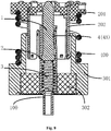
- Fig. 8 is a cross-sectional schematic view illustrating an electrical connector assembly according to an exemplary embodiment of the present disclosure
- Fig. 9 is a perspective schematic view illustrating an electrical connector according to another exemplary embodiment of the present disclosure
- Fig. 10 is a cross-sectional schematic view illustrating the electrical connector shown in Fig. 9
- Fig. 11 is a perspective schematic view illustrating a tube spring according to an exemplary embodiment of the present disclosure
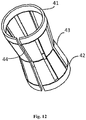
- Fig. 12 is a perspective schematic view illustrating an electrical connector housing according to another exemplary embodiment of the present disclosure.
- the electrical connector housing 2 of the electrical connector 100 comprises a body 21, a movable pin 1, a first elastic piece 3, and a second elastic piece 4.
- a cylindrical receiving portion 22 is formed in the body 21, and a part of the movable pin 1 is movably located in the receiving portion 22.
- the first elastic piece 3 is located in the receiving portion 22, the first end of the movable pin 1 movably protrudes out of the receiving portion 22 against elasticity of the first elastic piece 3.
- the second elastic piece 4 comprises a tube spring 4B provided between the side wall of the electrical connector housing 2 and the movable pin 1 and configured to be elastically abutted against the outer circumferential surface of the movable pin 1 and the side wall of the electrical connector housing 2, so that the movable pin 1 may be electrically connected to the electrical connector housing 2 by the first elastic piece 3 and the second elastic piece 4, respectively.
- the tube spring 4B comprises a plurality of elastic sheets 43 distributed at regular intervals in a circumference direction of the tube spring 4B, each of the elastic sheets 43 axially extending from two opposite ends 41, 42 of the tube spring toward each other and being formed as a V-shaped structure protruding toward the movable pin 1 so as to be elastically abutted against the outer circumferential surface of the movable pin 1.
- the two opposite ends 41, 42 of the tube spring 4B are in electrical contact with the side wall of the electrical connector housing 2, so that the movable pin 1 is electrically connected to the electrical connector housing 2 by the second elastic piece 4.
- the elastic piece 43 may also comprise an arc structure protruding toward the movable pin 1, for example.
- the number of the elastic pieces 43 may be one.
- the tube spring 4B is provided with an open slot 44 extending axially through the ends 41, 42 of the tube spring.
- the range of deformation of the tube spring 4B may be made larger to be applicable to the receiving portions 22 of different sizes (i.e., inner diameters) as much as possible by means of the open groove 44.
- the stopping portion 23 comprise a recess 23B formed in the body 21 and extending in the circumferential direction of the body 21, and the recess 23B may be interfered with the step between the first end 11 and the second end 12 of the movable pin 1, thereby preventing the movable pin 1 from slipping out of the receiving portion 22.
- the first end of the receiving portion 22 is provided with a flange 24 protruding radially inward to prevent impurities such as dust from entering the receiving portion 22, and to prevent the tube spring 4B from slipping out of the receiving portion 22.
- the electrical connector housing 2 is forms as a single conductive member by stamping a single sheet of metal.
- an electrical connector housing 2 comprising: a body 21 in which an receiving portion 22 is formed; and at least one elastic arm 4A integrally connected to the body 21 and configured to be elastically abutted against the outer circumferential surface of the movable pin 1 located in the receiving portion 22.
- the electrical connector assembly comprises the electrical connector 100 as described above any one embodiment and a cylinder 300 comprising an outer conductive cylinder 301 and an inner insulation cylinder 302.
- the inner insulation cylinder 302 is provided within the outer conductive cylinder 301, and the electrical connector 100 is mounted within the inner insulation cylinder 302 and is isolated from the outer conductive cylinder 301 by the inner insulation cylinder 302.
- the electrical connector housing 2 is provided with a positioning tab engaged with the inner insulation cylinder 302, the positioning tab comprising an upper positioning tab 25 engaged with an upper surface of the inner insulation cylinder 302 and a lower positioning tab 26 engaged with a lower surface of the inner insulation cylinder 302, and the electrical connector housing 2 and the inner insulation cylinder 302 are assembled together by the upper and lower positioning tabs.
- the electrical connector assembly further comprises a mating connector 200 including an insulation base 201 and a connection terminal 202 connected to the insulation base 201.
- the connection terminal 202 extends partially into the outer conductive cylinder 301 and is electrically connected to the outer conductive cylinder 301.
- the electrical connector assembly further comprises a third elastic piece 400, such as a spring, two ends of the third elastic piece 400 being elastically abutted against the insulation base 201 and the outer conductive cylinder 301, respectively, such that pressure provided by the third elastic piece 400 ensures that the first electronic component (e.g., a PCB board, not shown) at an upper end is stably and electrically connected with the second electronic component (e.g., a PCB board, not shown) at a lower end of the electrical connector assembly.
- a third elastic piece 400 such as a spring
- the second elastic piece is provided between the side wall of the receiving portion and the movable pin, and is elastically abutted against the outer circumferential surface of the movable pin, so that the movable pin is electrically connected to the electrical connector housing by the first elastic piece and the second elastic piece, respectively, thereby improving the reliability of electrical contact.
- the movable pin may be kept in electrical contact with the electrical connector housing by the first and the second elastic pieces even in the event of vibration or external force applied to the movable pin, thereby avoiding the occurrence of high frequency resonance and current transient interruption.
- the electrical connector assembly may comprise a radio frequency coaxial connector adapted to be electrically connected between the first electronic component and the second electronic component.
Landscapes
- Details Of Connecting Devices For Male And Female Coupling (AREA)
- Connector Housings Or Holding Contact Members (AREA)
Abstract
Description
- This application claims the benefit of Chinese Patent Application No.
CN201811578115.3 filed on December 21, 2018 - At least one embodiment of the present disclosure relates to an electrical connector, and more particularly, to an electrical connector housing capable of maintaining stably contact with a movable pin, an electrical connector including the electrical connector housing, and an electrical connector assembly including the electrical connector.
- Some existing electrical connectors generally comprises a structure of a movable pin which is placed in a receiving portion of a cylindrical electrical connector housing, a first end of the movable pin being located in the receiving portion and movably protruding out of the receiving portion against elasticity of a spring so as to be electrically connected to a connection terminal. The movable pin is generally kept in contact with the electrical connector housing by a slope at one end thereof. However, such contact is not stable enough, particularly when there is a vibration or external force applied to the movable pin, which results in poor contact between the movable pin and the electrical connector housing, thereby generating high frequency resonance and current transient interruption.
- An object of the present disclosure is to solve at least one of the above and other problems and defects existing in the prior arts.
- According to an exemplary embodiment of an aspect of the present disclosure, there is provided an electrical connector comprising: an electrical connector housing comprising a body in which an receiving portion is formed; at least one movable pin, a part of which is movably located in the receiving portion; a first elastic piece located in the receiving portion, a first end of each movable pin movably protruding out of the receiving portion against elasticity of the first elastic piece; and at least one second elastic piece located between a side wall of the receiving portion and the movable pin and configured to be elastically abutted against an outer circumferential surface of the movable pin. The movable pin is adapted to be electrically connected to the electrical connector housing by the first elastic piece and the second elastic piece.
- According to an embodiment of the present disclosure, the second elastic piece is an elastic arm integrally connected to the body.
- According to an embodiment of the present disclosure, each of the elastic arms is formed as an arc-shaped structure protruding from an inner side surface of the electrical connector housing toward the movable pin to be in elastic contact with the movable pin.
- According to an embodiment of the present disclosure, each of the elastic arms extends in an axial direction of the body.
- According to an embodiment of the present disclosure, a plurality of elastic arms are distributed at equal intervals in a circumference direction of the body.
- According to an embodiment of the present disclosure, the second elastic piece is a tube spring provided between a side wall of the electrical connector housing and the movable pin.
- According to an embodiment of the present disclosure, the tube spring comprises at least one elastic sheet each extending axially from two opposite ends of the tube spring toward each other, and being formed as an arc-shaped or a V-shaped structure protruding toward the movable pin.
- According to an embodiment of the present disclosure, the tube spring is provided with an open slot extending axially through the two opposite ends of the tube spring.
- According to an embodiment of the present disclosure, the movable pin is rod-shaped, a second end of the movable pin opposite to the first end being inserted into the receiving portion of the electrical connector housing, and an outer diameter of the first end being smaller than that of the second end.
- According to an embodiment of the present disclosure, the electrical connector further comprises at least one stopping portion engaged with the second end of the movable pin to prevent the movable pin from sliding out of the receiving portion.
- According to an embodiment of the present disclosure, the stopping portion is a stopping elastic sheet integrally connected to the body and protruding radially inward.
- According to an embodiment of the present disclosure, the stopping portion is a recess formed in the body.
- According to an embodiment of the present disclosure, the first end of the receiving portion is provided with a flange protruding radially inward.
- According to an embodiment of the present disclosure, first ends of two movable pins protrude out of opposite first and second ends of the receiving portion, , respectively and the first elastic piece is located between the two movable pins.
- According to an embodiment of the present disclosure, the first end of one movable pin protrudes out of a first end of the receiving portion, and the first elastic piece is located between a second end of the movable pin opposite to the first end and a second end of the receiving portion which is closed and is formed with an extension portion extending away from the first end of the receiving portion.
- According to an embodiment of the present disclosure, the electrical connector housing is formed by stamping.
- According to an exemplary embodiment of another aspect of the present disclosure, there is provided an electrical connector housing comprising: a body in which an receiving portion is formed; and at least one elastic arm integrally connected to the body and configured to be elastically abutted against an outer circumferential surface of a movable pin, a part of which is movably located in the receiving portion.
- According to an embodiment of the present disclosure, each of the elastic arms is formed as an arc-shaped structure protruding from an inner side surface of the electrical connector housing toward the movable pin to be in elastic contact with the movable pin.
- According to an embodiment of the present disclosure, each of the elastic arms extends in an axial direction of the body.
- According to an embodiment of the present disclosure, a plurality of elastic arms are distributed at equal intervals in a circumference direction of the body.
- According to an embodiment of the present disclosure, the electrical connector housing further comprises at least one stopping portion adapted to prevent the movable pin from sliding out of the receiving portion.
- According to an embodiment of the present disclosure, the stopping portion is a stopping elastic sheet integrally connected to the body and protruding radially inward.
- According to an embodiment of the present disclosure, the stopping portion is a recess formed in the body.
- According to an embodiment of the present disclosure, the first end of the receiving portion is provided with a flange protruding radially inward.
- According to an embodiment of the present disclosure, opposite first and second ends of the receiving portion are open.
- According to an embodiment of the present disclosure, a first end of the receiving portion is open and a second end of the receiving portion opposite the first end is closed, the second end of the receiving portion being formed with an extension extending portion away from the first end of the receiving portion.
- According to an embodiment of the present disclosure, the electrical connector housing is made by stamping.
- According to an exemplary embodiment of yet another aspect of the present disclosure, there is provided an electrical connector assembly comprising an electrical connector as described above; and a cylinder comprising: an outer conductive cylinder and an inner insulation cylinder provided in the outer conductive cylinder, the electrical connector being provided in the inner insulation cylinder and isolated from the outer conducting cylinder by the inner insulation cylinder.
- According to an embodiment of the present disclosure, the electrical connector housing is provided with a positioning tab engaged with the inner insulation cylinder.
- According to an embodiment of the present disclosure, the electrical connector assembly further comprises a mating connector including an insulation base and a connection terminal connected to the insulation base, the connection terminal extending partially into the outer conductive cylinder and electrically connected to the outer conductive cylinder.
- According to an embodiment of the present disclosure, the electrical connector assembly further comprises a third elastic piece, two opposite ends of the third elastic piece being elastically abutted against the insulation base and the outer conductive barrel, respectively.
- According to the electrical connector, the electrical connector housing and the electrical connector assembly of the above embodiments of the present disclosure, the second elastic piece is provided between the side wall of the receiving portion and the movable pin, and is elastically abutted against the outer circumferential surface of the movable pin, so that the movable pin is electrically connected to the electrical connector housing by the first elastic piece and the second elastic piece, thereby improving the reliability of electrical contact. The mobile pin may be kept in electrical contact with the electrical connector housing by the first and the second elastic pieces even in the event of vibration or external force applied to the movable pin, thereby avoiding the occurrence of high frequency resonance and current transient interruption.
- The above and other features of the present invention will become more apparent by describing in detail exemplary embodiments thereof with reference to the accompanying drawings, in which:
-
Fig. 1 is a perspective schematic view illustrating an electrical connector according to an exemplary embodiment of the present disclosure; -
Fig. 2 is a cross-sectional schematic view illustrating an electrical connector according to an exemplary embodiment of the present disclosure; -
Fig. 3 is a perspective schematic view illustrating an electrical connector housing according to an exemplary embodiment of the present disclosure; -
Fig. 4 is a perspective schematic view illustrating a movable pin according to an exemplary embodiment of the present disclosure; -
Fig. 5 is a perspective schematic view illustrating a first elastic piece according to an exemplary embodiment of the present disclosure; -
Fig. 6 is a perspective schematic view illustrating an electrical connector according to another exemplary embodiment of the present disclosure; -
Fig. 7 is a cross-sectional schematic view illustrating the electrical connector shown infig. 6 ; -
Fig. 8 is a cross-sectional schematic view illustrating an electrical connector assembly according to an exemplary embodiment of the present disclosure; -
Fig. 9 is a perspective schematic view illustrating an electrical connector according to another exemplary embodiment of the present disclosure; -
Fig. 10 is a cross-sectional schematic view illustrating the electrical connector shown inFig. 9 ; -
Fig. 11 is a perspective schematic view illustrating a tube spring according to an exemplary embodiment of the present disclosure; -
Fig. 12 is a perspective schematic view illustrating an electrical connector housing according to another exemplary embodiment of the present disclosure; -
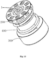
Fig. 13 is a perspective schematic view illustrating an electrical connector assembly according to an exemplary embodiment of the present disclosure; and -
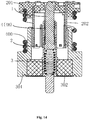
Fig. 14 is a cross-sectional schematic view illustrating an electrical connector assembly according to an exemplary embodiment of the present disclosure. - Although the present disclosure will be fully described with reference to the accompanying drawings including the preferred embodiments of the disclosure, before the descriptions, it is should to be understand any modifications may be made in the described disclosure herein by those skilled in the art and obtained the disadvantages of the disclosure at the same time. Therefore, the above description is to be understood as a broad disclosure for those skilled in the art, and is not intended to limit the exemplary embodiments described herein.
- In addition, in the following detailed description, for purposes of explanation, numerous specific details are set forth in order to provide a thorough understanding of the disclosed embodiments. It will be apparent, however, that one or more embodiments may be practiced without these specific details. In other instances, well-known structures and devices are schematically shown in order to simplify the drawing.
- According to a general technical concept of the present disclosure, there is provided an electrical connector comprising: an electrical connector housing comprising a body in which an receiving portion is formed; at least one movable pin, a part of which is movably located in the receiving portion; a first elastic piece located in the receiving portion, a first end of each movable pin movably protruding out of the receiving portion against elasticity of the first elastic piece; and at least one second elastic piece located between a side wall of the receiving portion and the movable pin and configured to be elastically abutted against an outer circumferential surface of the movable pin. The movable pin is adapted to be electrically connected to the electrical connector housing by the first elastic piece and the second elastic piece.
- According to another general technical concept of the present disclosure, there is provided an electrical connector housing comprising: a body in which an receiving portion is formed; and at least one elastic arm integrally connected to the body and configured to be elastically abutted against an outer circumferential surface of a movable pin, a part of which is movably located in the receiving portion.
- According to yet another general technical concept of the present disclosure, there is provided an electrical connector assembly comprising an electrical connector as described above; and a cylinder comprising: an outer conductive cylinder and an inner insulation cylinder provided in the outer conductive cylinder, the electrical connector being provided in the inner insulation cylinder and isolated from the outer conducting cylinder by the inner insulation cylinder.
-
Fig. 1 is a perspective schematic view illustrating an electrical connector according to an exemplary embodiment of the present disclosure;Fig. 2 is a cross-sectional schematic view illustrating an electrical connector according to an exemplary embodiment of the present disclosure;Fig. 3 is a perspective schematic view illustrating an electrical connector housing according to an exemplary embodiment of the present disclosure;Fig. 4 is a perspective schematic view illustrating a movable pin according to an exemplary embodiment of the present disclosure; andFig. 5 is a perspective schematic view illustrating a first elastic piece according to an exemplary embodiment of the present disclosure. - As shown in
Figs. 1 to 5 , anelectrical connector 100 according to an embodiment of the present disclosure comprises: a cylindricalelectrical connector housing 2 comprising abody 21, onemovable pin 1, a firstelastic piece 3 and a plurality of secondelastic pieces 4. A cylindrical receivingportion 22 is formed in thebody 21, a part of themovable pin 1 is movably located in the receivingportion 22, and the firstelastic piece 3 is located in the receivingportion 22. Afirst end 11 of themovable pin 1 movably protrudes out of the receivingportion 22 against elasticity of the firstelastic piece 3. The plurality of secondelastic pieces 4 are located between a side wall of the receivingportion 22 and themovable pin 1 and are configured to be elastically abutted against an outer circumferential surface of themovable pin 1, so that themovable pin 1 may be electrically connected to theelectrical connector housing 2 by the firstelastic piece 3 and the secondelastic pieces 4. In this embodiment, the plurality of secondelastic pieces 4 comprises a plurality ofelastic arms 4A integrally connected to thebody 21 and are distributed at intervals in a circumferential direction of the receivingportion 22, so that themovable pin 1 may be kept in electrical contact with theelectrical connector housing 2 by the firstelastic piece 3 and the secondelastic pieces 4 in the event of vibration or external force applied to themovable pin 1. - In an exemplary embodiment, as shown in
Figs. 1 to 3 , each of theelastic arms 4A is formed as an arc-shaped structure protruding from the inner side surface of theelectrical connector housing 2 toward themovable pin 1 to be in elastic contact with themovable pin 1, thereby making themovable pin 1 be in reliable electrical contact with theelectrical connector housing 2. - In an exemplary embodiment, as shown in
Fig. 2 , thefirst end 11 of onemovable pin 1 protrudes out of a first end of the receivingportion 22 to be electrically connected to a first electronic component (e.g., a PCB board, not shown), and the firstelastic piece 3 is located between asecond end 12 of themovable pin 1 opposite to thefirst end 11 and a second end of the receivingportion 22 which is closed and is formed with anextension portion 27 extending away from the first end of the receivingportion 22 to be electrically connected to a second electronic component (e.g., a PCB board, not shown). - In an exemplary embodiment, as shown in
Figs. 1 to 3 , each of theelastic arms 4A extends in an axial direction of thebody 21, thereby facilitating insertion of themovable pin 1 into the receivingportion 22 of theelectrical connector housing 2. It is appreciated for those skilled in the art that in other embodiments of the present disclosure, theelastic arm 4A may also extend in a circumferential direction of thebody 21, for example. - In an exemplary embodiment, as shown in
Figs. 1 to 3 , the plurality ofelastic arms 4A are distributed at regular intervals in the circumferential direction of thebody 21, thereby making it easy for themovable pin 1 to be positioned at the center of the receivingportion 22 by the elastic force of the plurality ofelastic arms 4A. That is, the axis of themovable pin 1 is coincided with the axis of the receivingportion 22. - In an exemplary embodiment, as shown in
Figs. 2 and4 , themovable pin 1 is rod-shaped, thefirst end 11 of themovable pin 1 protruding out of the receivingportion 22 of theelectrical connector housing 2, thesecond end 12 of themovable pin 1 opposite to thefirst end 11 being inserted into the receivingportion 22 of theelectrical connector housing 2, and an outer diameter of thefirst end 11 being smaller than that of thesecond end 12. That is, a step is provided between thefirst end 11 and thesecond end 12 of themovable pin 1 so that themovable pin 1 is held in theelectrical connector housing 2 by the step. - In an exemplary embodiment, the
electrical connector housing 2 further comprises at least one stoppingportion 23 engaged with thesecond end 12 of themovable pin 1 to prevent themovable pin 1 from sliding out of the receivingportion 22. As shown inFigs. 1 to 3 , the stoppingportion 23 comprises a stoppingelastic sheet 23A integrally connected to thebody 21 and radially protruding inward. A plurality of stoppingelastic pieces 23A are distributed at regular intervals in the circumferential direction of the receivingportion 22, and the stoppingelastic sheets 23A extend in the axial direction of thebody 21. A connection between the stoppingelastic sheet 23A and thebody 21 is close to the first end of the receivingportion 22, and an end of the stoppingelastic sheet 23A opposite to the connection with thebody 21 is far away from the first end of the receivingportion 22, so that the stoppingelastic sheet 23A is deformed by a force of themovable pin 1 to pass themovable pin 1 during the process of inserting themovable pin 1 into the receivingportion 22. When themovable pin 1 reaches the preset position, the stoppingelastic sheet 23A is restored by its elastic force, and may be interfered with the step between thefirst end 11 and thesecond end 12 of themovable pin 1, thereby preventing themovable pin 1 from slipping out of the receivingportion 22. - As shown in
Figs 1-4 , in the illustrated embodiment, theelectrical connector housing 2 is formed as a single conductive member by stamping a single sheet of metal. -
Fig. 6 is a perspective schematic view illustrating an electrical connector according to another exemplary embodiment of the present disclosure; andFig. 7 is a cross-sectional schematic view illustrating the electrical connector shown infig. 6 . - In an exemplary embodiment, as shown in
Figs. 6 and7 , theelectrical connector 100 comprises twomovable pins 1, first ends 11 of the twomovable pins 1 protruding out of the opposite first and second ends of the receivingportion 22 to be electrically connected to the first electronic component (e.g., a PCB board, not shown) and the second electronic component (e.g., a PCB board, not shown), respectively. The firstelastic piece 3 is located between the twomovable pins 1. That is, two opposite ends of the firstelastic piece 3 are elastically abutted against the twomovable pins 1, respectively. -
Fig. 8 is a cross-sectional schematic view illustrating an electrical connector assembly according to an exemplary embodiment of the present disclosure;Fig. 9 is a perspective schematic view illustrating an electrical connector according to another exemplary embodiment of the present disclosure;Fig. 10 is a cross-sectional schematic view illustrating the electrical connector shown inFig. 9 ;Fig. 11 is a perspective schematic view illustrating a tube spring according to an exemplary embodiment of the present disclosure; andFig. 12 is a perspective schematic view illustrating an electrical connector housing according to another exemplary embodiment of the present disclosure. - In an exemplary embodiment, as shown in
Figs. 9 to 12 , theelectrical connector housing 2 of theelectrical connector 100 comprises abody 21, amovable pin 1, a firstelastic piece 3, and a secondelastic piece 4. A cylindrical receivingportion 22 is formed in thebody 21, and a part of themovable pin 1 is movably located in the receivingportion 22. The firstelastic piece 3 is located in the receivingportion 22, the first end of themovable pin 1 movably protrudes out of the receivingportion 22 against elasticity of the firstelastic piece 3. The secondelastic piece 4 comprises atube spring 4B provided between the side wall of theelectrical connector housing 2 and themovable pin 1 and configured to be elastically abutted against the outer circumferential surface of themovable pin 1 and the side wall of theelectrical connector housing 2, so that themovable pin 1 may be electrically connected to theelectrical connector housing 2 by the firstelastic piece 3 and the secondelastic piece 4, respectively. - As shown in
Fig. 10 , thetube spring 4B comprises a plurality ofelastic sheets 43 distributed at regular intervals in a circumference direction of thetube spring 4B, each of theelastic sheets 43 axially extending from two opposite ends 41, 42 of the tube spring toward each other and being formed as a V-shaped structure protruding toward themovable pin 1 so as to be elastically abutted against the outer circumferential surface of themovable pin 1. The two opposite ends 41, 42 of thetube spring 4B are in electrical contact with the side wall of theelectrical connector housing 2, so that themovable pin 1 is electrically connected to theelectrical connector housing 2 by the secondelastic piece 4. It is appreciated for those skilled in the art that in other embodiments of the present disclosure, theelastic piece 43 may also comprise an arc structure protruding toward themovable pin 1, for example. In addition, the number of theelastic pieces 43 may be one. - Referring again to
Fig. 10 , thetube spring 4B is provided with anopen slot 44 extending axially through theends tube spring 4B may be made larger to be applicable to the receivingportions 22 of different sizes (i.e., inner diameters) as much as possible by means of theopen groove 44. - In an exemplary embodiment, as shown in
Figs. 10 and13 , the stoppingportion 23 comprise arecess 23B formed in thebody 21 and extending in the circumferential direction of thebody 21, and therecess 23B may be interfered with the step between thefirst end 11 and thesecond end 12 of themovable pin 1, thereby preventing themovable pin 1 from slipping out of the receivingportion 22. - In one exemplary embodiment, as shown in
Figs. 10 and11 , the first end of the receivingportion 22 is provided with aflange 24 protruding radially inward to prevent impurities such as dust from entering the receivingportion 22, and to prevent thetube spring 4B from slipping out of the receivingportion 22. - In the illustrated embodiment, as shown in
Figs. 9-10 , theelectrical connector housing 2 is forms as a single conductive member by stamping a single sheet of metal. - According to an embodiment of another aspect of the present disclosure, there is provided an
electrical connector housing 2 comprising: abody 21 in which an receivingportion 22 is formed; and at least oneelastic arm 4A integrally connected to thebody 21 and configured to be elastically abutted against the outer circumferential surface of themovable pin 1 located in the receivingportion 22. - According to an embodiment of a further aspect of the present disclosure, there is provided an electrical connector assembly. As shown in figures, the electrical connector assembly comprises the
electrical connector 100 as described above any one embodiment and acylinder 300 comprising an outerconductive cylinder 301 and aninner insulation cylinder 302. Theinner insulation cylinder 302 is provided within the outerconductive cylinder 301, and theelectrical connector 100 is mounted within theinner insulation cylinder 302 and is isolated from the outerconductive cylinder 301 by theinner insulation cylinder 302. - In some exemplary embodiments, as shown in
Figs. 1 ,3 ,6 ,9 ,10 ,11 and13 , theelectrical connector housing 2 is provided with a positioning tab engaged with theinner insulation cylinder 302, the positioning tab comprising anupper positioning tab 25 engaged with an upper surface of theinner insulation cylinder 302 and alower positioning tab 26 engaged with a lower surface of theinner insulation cylinder 302, and theelectrical connector housing 2 and theinner insulation cylinder 302 are assembled together by the upper and lower positioning tabs. - In some exemplary embodiments, as shown in
Figs. 8 ,13 and14 , the electrical connector assembly further comprises amating connector 200 including aninsulation base 201 and aconnection terminal 202 connected to theinsulation base 201. Theconnection terminal 202 extends partially into the outerconductive cylinder 301 and is electrically connected to the outerconductive cylinder 301. - In some exemplary embodiments, as shown in
Figs. 8 and13 , the electrical connector assembly further comprises a thirdelastic piece 400, such as a spring, two ends of the thirdelastic piece 400 being elastically abutted against theinsulation base 201 and the outerconductive cylinder 301, respectively, such that pressure provided by the thirdelastic piece 400 ensures that the first electronic component (e.g., a PCB board, not shown) at an upper end is stably and electrically connected with the second electronic component (e.g., a PCB board, not shown) at a lower end of the electrical connector assembly. - According to the electrical connector, the electrical connector housing and the electrical connector assembly of the above embodiments of the present disclosure, the second elastic piece is provided between the side wall of the receiving portion and the movable pin, and is elastically abutted against the outer circumferential surface of the movable pin, so that the movable pin is electrically connected to the electrical connector housing by the first elastic piece and the second elastic piece, respectively, thereby improving the reliability of electrical contact. The movable pin may be kept in electrical contact with the electrical connector housing by the first and the second elastic pieces even in the event of vibration or external force applied to the movable pin, thereby avoiding the occurrence of high frequency resonance and current transient interruption. The electrical connector assembly may comprise a radio frequency coaxial connector adapted to be electrically connected between the first electronic component and the second electronic component.
- It will be understood by those skilled in the art that the above-described embodiments are exemplary and that modifications may be made by those skilled in the art, and that structures described in the various embodiments may be freely combined without conflict in structure or principle, thereby implementing a wider variety of heat sinks and housing assemblies while solving the technical problems of the present disclosure.
- Although the preferred embodiments of the present disclosure have been described in detail, it will be apparent to those skilled in the art that various changes and modifications can be made without departing from the scope and spirit of the appended claims, and the disclosure is not limited to the exemplary embodiments illustrated in the specification.
Claims (15)
- An electrical connector (100) comprising:an electrical connector housing (2) comprising a body (21) in which an receiving portion (22) is formed;at least one movable pin(1), a part of which is movably located in the receiving portion;a first elastic piece (3) located in the receiving portion, a first end (11) of each movable pin movably protruding out of the receiving portion against elasticity of the first elastic piece; andat least one second elastic piece (4) located between a side wall of the receiving portion and the movable pin and configured to be elastically abutted against an outer circumferential surface of the movable pin,characterized in that the movable pin is adapted to be electrically connected to the electrical connector housing by the first elastic piece and the second elastic piece.
- The electrical connector according to claim 1, wherein the second elastic piece comprises an elastic arm (4A) integrally connected to the body,
preferably, each of the elastic arms is formed as an arc-shaped structure protruding from an inner side surface of the electrical connector housing toward the movable pin to be in elastic contact with the movable pin, and
more preferably, each of the elastic arms extends in an axial direction of the body. - The electrical connector according to claim 1, wherein the second elastic piece comprises a tube spring provided between a side wall of the electrical connector housing and the movable pin,
preferably, the tube spring comprises at least one elastic sheet (43) each extending axially from two opposite ends of the tube spring toward each other, and being formed as an arc-shaped or a V-shaped structure protruding toward the movable pin, and
more preferably, the tube spring is provided with an open slot (44) extending axially through the two opposite ends of the tube spring. - The electrical connector according to any one of claims 1-3, wherein the movable pin is rod-shaped, a second end (12) of the movable pin opposite to the first end being inserted into the receiving portion of the electrical connector housing, and an outer diameter of the first end being smaller than that of the second end.
- The electrical connector according to claim 4, further comprising at least one stopping portion (23) engaged with the second end of the movable pin to prevent the movable pin from sliding out of the receiving portion, and
preferably, the stopping portion comprises a stopping elastic sheet (23A) integrally connected to the body and protruding radially inward; or the stopping portion comprises a recess (23B) formed in the body. - The electrical connector according to any one of any one of claims 1-5, wherein first ends of two movable pins protrude out of opposite first and second ends of the receiving portion, respectively, and the first elastic piece is located between the two movable pins.
- The electrical connector according to any one of claims 1-6, wherein the first end of one movable pin protrudes out of a first end of the receiving portion, and the first elastic piece is located between a second end of the movable pin opposite to the first end and a second end of the receiving portion which is closed and is formed with an extension portion (27) extending away from the first end of the receiving portion.
- An electrical connector housing (2) characterized in that comprises:a body (21) in which an receiving portion is formed; andat least one elastic arm (4A) integrally connected to the body and configured to be elastically abutted against an outer circumferential surface of a movable pin (1), a part of which is movably located in the receiving portion.
- The electrical connector housing according to claim 8, wherein each of the elastic arms is formed as an arc-shaped structure protruding from an inner side surface of the electrical connector housing toward the movable pin to be in elastic contact with the movable pin,
preferably, each of the elastic arms extends in an axial direction of the body, and
more preferably, a plurality of elastic arms are distributed at regular intervals in a circumference direction of the body. - The electrical connector housing according to claim 8 or 9, further comprising at least one stopping portion (23) adapted to prevent the movable pin from sliding out of the receiving portion, and
preferably, the stopping portion comprises a stopping elastic sheet (23A) integrally connected to the body and protruding radially inward; or the stopping portion comprises a recess (23B) formed in the body. - The electrical connector housing of any one of claims 8-10, wherein opposite first and second ends of the receiving portion are open, or
a first end of the receiving portion is open and a second end of the receiving portion opposite the first end is closed, the second end of the receiving portion being formed with an extension portion extending away from the first end of the receiving portion. - An electrical connector assembly characterized in that comprises:an electrical connector according to any one of claims 1-7; anda cylinder (300) comprising:an outer conductive cylinder (301), andan inner insulation cylinder (302) provided in the outer conductive cylinder, the electrical connector being provided in the inner insulation cylinder and isolated from the outer conducting cylinder by the inner insulation cylinder.
- The electrical connector assembly according to claim 12, wherein the electrical connector housing is provided with a positioning tab engaged with the inner insulation cylinder.
- The electrical connector assembly according to claim 12 or 13, further comprising a mating connector including an insulation base and a connection terminal connected to the insulation base, the connection terminal extending partially into the outer conductive cylinder and electrically connected to the outer conductive cylinder.
- The electrical connector assembly according to claim 14, further comprising a third elastic piece, two opposite ends of the third elastic piece being elastically abutted against the insulation base and the outer conductive barrel, respectively.
Applications Claiming Priority (1)
| Application Number | Priority Date | Filing Date | Title |
|---|---|---|---|
| CN201811578115.3A CN111355076A (en) | 2018-12-21 | 2018-12-21 | Electrical connector housing, electrical connector, electrical connector assembly |
Publications (3)
| Publication Number | Publication Date |
|---|---|
| EP3671968A2 true EP3671968A2 (en) | 2020-06-24 |
| EP3671968A3 EP3671968A3 (en) | 2020-09-23 |
| EP3671968B1 EP3671968B1 (en) | 2024-05-01 |
Family
ID=68944138
Family Applications (1)
| Application Number | Title | Priority Date | Filing Date |
|---|---|---|---|
| EP19216850.8A Active EP3671968B1 (en) | 2018-12-21 | 2019-12-17 | Electrical connector housing, electrical connector and electrical connector assembly |
Country Status (4)
| Country | Link |
|---|---|
| US (1) | US11355881B2 (en) |
| EP (1) | EP3671968B1 (en) |
| KR (1) | KR102800248B1 (en) |
| CN (1) | CN111355076A (en) |
Families Citing this family (15)
| Publication number | Priority date | Publication date | Assignee | Title |
|---|---|---|---|---|
| USD851048S1 (en) * | 2017-01-30 | 2019-06-11 | Shawn Duggan | Housing for electrical or cabling wires |
| USD904314S1 (en) * | 2017-01-30 | 2020-12-08 | Shawn Duggan | Electrical and cabling housing |
| KR102013690B1 (en) * | 2018-11-23 | 2019-08-23 | 주식회사 기가레인 | Board-mating connector integrated with housing of electric instrument and Manufacturing method thereof |
| EP3888195B1 (en) | 2018-11-30 | 2026-04-15 | Corning Optical Communications RF LLC | Compressible electrical contacts with divaricated-cut sections |
| TW202539103A (en) * | 2019-03-11 | 2025-10-01 | 美商山姆科技公司 | Electrical contact, array of electrical contacts, cellular transmission tower and chip testing system |
| USD936610S1 (en) * | 2019-11-30 | 2021-11-23 | Corning Optical Communications Rf Llc | Compressible electrical contact |
| WO2021108080A1 (en) | 2019-11-30 | 2021-06-03 | Corning Optical Communications Rf Llc | Connector assemblies |
| USD936611S1 (en) * | 2019-11-30 | 2021-11-23 | Corning Optical Communications Rf Llc | Compressible electrical contact |
| JP7455603B2 (en) * | 2020-02-12 | 2024-03-26 | 株式会社エンプラス | contact pins and sockets |
| CN113285265B (en) * | 2020-02-19 | 2023-06-16 | 上海莫仕连接器有限公司 | Electric connector and electric connector combination |
| US12212083B2 (en) | 2020-11-30 | 2025-01-28 | Corning Optical Communications Rf Llc | Compressible electrical assemblies with divaricated-cut sections |
| CN114914724B (en) * | 2021-02-09 | 2025-10-03 | 泰科电子(上海)有限公司 | Conductive terminals, electrical connectors |
| JP2023026039A (en) * | 2021-08-12 | 2023-02-24 | 山一電機株式会社 | Probe and test socket |
| US20230335959A1 (en) * | 2022-04-19 | 2023-10-19 | Itt Manufacturing Enterprises, Llc | Turnable electrical connector and cable assembly |
| CN116466258B (en) * | 2023-04-21 | 2024-05-17 | 江苏谷英系统工程有限公司 | Online detection system and early warning method for uninterruptible power supply |
Family Cites Families (30)
| Publication number | Priority date | Publication date | Assignee | Title |
|---|---|---|---|---|
| JP3509038B2 (en) * | 1994-12-01 | 2004-03-22 | ホシデン株式会社 | Slide pin contact |
| JP3156957B2 (en) * | 1995-08-29 | 2001-04-16 | 矢崎総業株式会社 | connector |
| JP2001021615A (en) * | 1999-07-06 | 2001-01-26 | Yokowo Co Ltd | Contact probe of socket for inspecting bga |
| US6814626B2 (en) * | 2002-10-21 | 2004-11-09 | L & K Precision Industry Co., Ltd. | Electrical connector for chargeable battery |
| US6861862B1 (en) * | 2003-03-17 | 2005-03-01 | John O. Tate | Test socket |
| DE20315894U1 (en) * | 2003-10-16 | 2003-12-18 | Feinmetall Gmbh | High current carrying spring contact pin has good contact between pin and housing sleeve maintained by a radial contact spring element |
| JP4224389B2 (en) * | 2003-12-16 | 2009-02-12 | 株式会社ヨコオ | Spring connector |
| DE102004033864A1 (en) * | 2004-07-13 | 2006-02-16 | Era-Contact Gmbh | Electrical pressure contact |
| US7097460B2 (en) * | 2005-02-01 | 2006-08-29 | Harris Corporation | Coaxial connector |
| ITGE20060052A1 (en) * | 2006-05-05 | 2007-11-06 | Hypertac S P A | Contact for electrical or electronic connections. |
| CN201149917Y (en) * | 2007-12-14 | 2008-11-12 | 东莞中探探针有限公司 | spring-loaded contact probe |
| CN201149918Y (en) * | 2007-12-14 | 2008-11-12 | 东莞中探探针有限公司 | Spring type contact probe |
| CN201336427Y (en) * | 2008-12-12 | 2009-10-28 | 富港电子(东莞)有限公司 | Probe needle |
| CN201352603Y (en) * | 2008-12-12 | 2009-11-25 | 富港电子(东莞)有限公司 | Probe connector |
| CN201383577Y (en) * | 2009-03-26 | 2010-01-13 | 长盛科技股份有限公司 | Battery connector |
| JP2011096606A (en) * | 2009-11-02 | 2011-05-12 | Smk Corp | Pogo pin type pressure-contact connector |
| JP2011108445A (en) * | 2009-11-16 | 2011-06-02 | Hirose Electric Co Ltd | Coaxial electric connector for circuit board |
| CN201789125U (en) * | 2010-08-27 | 2011-04-06 | 富港电子(东莞)有限公司 | probe |
| CN202159804U (en) * | 2010-12-24 | 2012-03-07 | 富港电子(东莞)有限公司 | Probe connector |
| CN202025900U (en) * | 2011-03-25 | 2011-11-02 | 富港电子(东莞)有限公司 | Probe connector |
| JP5316821B2 (en) * | 2011-05-11 | 2013-10-16 | Smk株式会社 | Pressure contact type connector |
| JP5765674B2 (en) * | 2012-09-28 | 2015-08-19 | Smk株式会社 | Spring connector and how to assemble this spring connector |
| CN203690558U (en) * | 2013-12-17 | 2014-07-02 | 信连精密工业有限公司 | Probe connector structure |
| US9748680B1 (en) * | 2016-06-28 | 2017-08-29 | Intel Corporation | Multiple contact pogo pin |
| CN108346874B (en) * | 2017-01-24 | 2024-04-02 | 泰科电子(上海)有限公司 | Electric connector |
| CN206789831U (en) * | 2017-02-24 | 2017-12-22 | 立讯精密工业股份有限公司 | Radio frequency connector |
| CN107359447A (en) * | 2017-07-11 | 2017-11-17 | 深圳市为致康科技有限公司 | A kind of spring thimble and preparation method of built-in hat spring |
| JP6909698B2 (en) * | 2017-10-05 | 2021-07-28 | 株式会社ヨコオ | Spring connector |
| CN107946813A (en) * | 2017-11-21 | 2018-04-20 | 东莞市星全工业有限公司 | Spring probe |
| KR101926502B1 (en) | 2018-03-27 | 2018-12-07 | 주식회사 기가레인 | board mating connector including PIMD enhanced signal contact part |
-
2018
- 2018-12-21 CN CN201811578115.3A patent/CN111355076A/en active Pending
-
2019
- 2019-12-16 KR KR1020190167422A patent/KR102800248B1/en active Active
- 2019-12-17 EP EP19216850.8A patent/EP3671968B1/en active Active
- 2019-12-19 US US16/720,263 patent/US11355881B2/en active Active
Also Published As
| Publication number | Publication date |
|---|---|
| EP3671968B1 (en) | 2024-05-01 |
| CN111355076A (en) | 2020-06-30 |
| KR102800248B1 (en) | 2025-04-23 |
| US11355881B2 (en) | 2022-06-07 |
| US20200203873A1 (en) | 2020-06-25 |
| KR20200078357A (en) | 2020-07-01 |
| EP3671968A3 (en) | 2020-09-23 |
Similar Documents
| Publication | Publication Date | Title |
|---|---|---|
| US11355881B2 (en) | Electrical connector housing, electrical connector and electrical connector assembly | |
| US11381012B2 (en) | Electrical connector and electrical connector assembly | |
| US10931051B2 (en) | Connector and receptacle | |
| EP3537546B1 (en) | Connector | |
| EP3550669B1 (en) | Coaxial connector | |
| US11264753B2 (en) | Connector | |
| CN107154545B (en) | Round terminal with low profile cap | |
| EP3930114B1 (en) | Sag limiting coaxial connector | |
| US11404808B2 (en) | Coaxial connector and board-to-board connector assembly | |
| US10707595B2 (en) | Multi-pin connector block assembly | |
| US11664617B2 (en) | Electrical terminal, method for manufacturing elastic terminal, electrical connector and electronic device | |
| US11196202B2 (en) | Electrical connector and electronic device | |
| CN113783016A (en) | An inter-board radio frequency connector | |
| CN112928515A (en) | Electrical connector and electrical connector assembly | |
| CN110571551B (en) | Electrical plug connector for circuit boards | |
| CN107565250A (en) | Connector | |
| CN212968376U (en) | Connector with a locking member | |
| CN211530232U (en) | Electrical connector and electrical connector assembly | |
| CN210866559U (en) | Coaxial Connectors and Board-to-Board Connector Assemblies | |
| CN210430187U (en) | Electrical connector and electrical connector assembly | |
| CN206022693U (en) | Adapter | |
| CN210052884U (en) | Connector with a locking member | |
| CN111916941A (en) | Connector | |
| CN223487401U (en) | Withstand voltage grafting device | |
| CN114914724B (en) | Conductive terminals, electrical connectors |
Legal Events
| Date | Code | Title | Description |
|---|---|---|---|
| PUAI | Public reference made under article 153(3) epc to a published international application that has entered the european phase |
Free format text: ORIGINAL CODE: 0009012 |
|
| STAA | Information on the status of an ep patent application or granted ep patent |
Free format text: STATUS: THE APPLICATION HAS BEEN PUBLISHED |
|
| AK | Designated contracting states |
Kind code of ref document: A2 Designated state(s): AL AT BE BG CH CY CZ DE DK EE ES FI FR GB GR HR HU IE IS IT LI LT LU LV MC MK MT NL NO PL PT RO RS SE SI SK SM TR |
|
| AX | Request for extension of the european patent |
Extension state: BA ME |
|
| PUAL | Search report despatched |
Free format text: ORIGINAL CODE: 0009013 |
|
| AK | Designated contracting states |
Kind code of ref document: A3 Designated state(s): AL AT BE BG CH CY CZ DE DK EE ES FI FR GB GR HR HU IE IS IT LI LT LU LV MC MK MT NL NO PL PT RO RS SE SI SK SM TR |
|
| AX | Request for extension of the european patent |
Extension state: BA ME |
|
| RIC1 | Information provided on ipc code assigned before grant |
Ipc: H01R 24/38 20110101ALI20200819BHEP Ipc: H01R 13/24 20060101AFI20200819BHEP Ipc: H01R 12/71 20110101ALI20200819BHEP Ipc: H01R 13/187 20060101ALI20200819BHEP Ipc: G01R 1/067 20060101ALI20200819BHEP |
|
| STAA | Information on the status of an ep patent application or granted ep patent |
Free format text: STATUS: REQUEST FOR EXAMINATION WAS MADE |
|
| 17P | Request for examination filed |
Effective date: 20210322 |
|
| RBV | Designated contracting states (corrected) |
Designated state(s): AL AT BE BG CH CY CZ DE DK EE ES FI FR GB GR HR HU IE IS IT LI LT LU LV MC MK MT NL NO PL PT RO RS SE SI SK SM TR |
|
| STAA | Information on the status of an ep patent application or granted ep patent |
Free format text: STATUS: EXAMINATION IS IN PROGRESS |
|
| 17Q | First examination report despatched |
Effective date: 20220401 |
|
| GRAJ | Information related to disapproval of communication of intention to grant by the applicant or resumption of examination proceedings by the epo deleted |
Free format text: ORIGINAL CODE: EPIDOSDIGR1 |
|
| GRAP | Despatch of communication of intention to grant a patent |
Free format text: ORIGINAL CODE: EPIDOSNIGR1 |
|
| GRAP | Despatch of communication of intention to grant a patent |
Free format text: ORIGINAL CODE: EPIDOSNIGR1 |
|
| STAA | Information on the status of an ep patent application or granted ep patent |
Free format text: STATUS: GRANT OF PATENT IS INTENDED |
|
| GRAS | Grant fee paid |
Free format text: ORIGINAL CODE: EPIDOSNIGR3 |
|
| INTG | Intention to grant announced |
Effective date: 20240229 |
|
| GRAA | (expected) grant |
Free format text: ORIGINAL CODE: 0009210 |
|
| STAA | Information on the status of an ep patent application or granted ep patent |
Free format text: STATUS: THE PATENT HAS BEEN GRANTED |
|
| P01 | Opt-out of the competence of the unified patent court (upc) registered |
Effective date: 20240320 |
|
| AK | Designated contracting states |
Kind code of ref document: B1 Designated state(s): AL AT BE BG CH CY CZ DE DK EE ES FI FR GB GR HR HU IE IS IT LI LT LU LV MC MK MT NL NO PL PT RO RS SE SI SK SM TR |
|
| REG | Reference to a national code |
Ref country code: GB Ref legal event code: FG4D |
|
| REG | Reference to a national code |
Ref country code: CH Ref legal event code: EP |
|
| REG | Reference to a national code |
Ref country code: IE Ref legal event code: FG4D |
|
| REG | Reference to a national code |
Ref country code: DE Ref legal event code: R096 Ref document number: 602019051290 Country of ref document: DE |
|
| REG | Reference to a national code |
Ref country code: LT Ref legal event code: MG9D |
|
| REG | Reference to a national code |
Ref country code: NL Ref legal event code: MP Effective date: 20240501 |
|
| PG25 | Lapsed in a contracting state [announced via postgrant information from national office to epo] |
Ref country code: IS Free format text: LAPSE BECAUSE OF FAILURE TO SUBMIT A TRANSLATION OF THE DESCRIPTION OR TO PAY THE FEE WITHIN THE PRESCRIBED TIME-LIMIT Effective date: 20240901 |
|
| PG25 | Lapsed in a contracting state [announced via postgrant information from national office to epo] |
Ref country code: BG Free format text: LAPSE BECAUSE OF FAILURE TO SUBMIT A TRANSLATION OF THE DESCRIPTION OR TO PAY THE FEE WITHIN THE PRESCRIBED TIME-LIMIT Effective date: 20240501 |
|
| PG25 | Lapsed in a contracting state [announced via postgrant information from national office to epo] |
Ref country code: HR Free format text: LAPSE BECAUSE OF FAILURE TO SUBMIT A TRANSLATION OF THE DESCRIPTION OR TO PAY THE FEE WITHIN THE PRESCRIBED TIME-LIMIT Effective date: 20240501 Ref country code: FI Free format text: LAPSE BECAUSE OF FAILURE TO SUBMIT A TRANSLATION OF THE DESCRIPTION OR TO PAY THE FEE WITHIN THE PRESCRIBED TIME-LIMIT Effective date: 20240501 |
|
| PG25 | Lapsed in a contracting state [announced via postgrant information from national office to epo] |
Ref country code: GR Free format text: LAPSE BECAUSE OF FAILURE TO SUBMIT A TRANSLATION OF THE DESCRIPTION OR TO PAY THE FEE WITHIN THE PRESCRIBED TIME-LIMIT Effective date: 20240802 |
|
| PG25 | Lapsed in a contracting state [announced via postgrant information from national office to epo] |
Ref country code: PT Free format text: LAPSE BECAUSE OF FAILURE TO SUBMIT A TRANSLATION OF THE DESCRIPTION OR TO PAY THE FEE WITHIN THE PRESCRIBED TIME-LIMIT Effective date: 20240902 |
|
| REG | Reference to a national code |
Ref country code: AT Ref legal event code: MK05 Ref document number: 1683708 Country of ref document: AT Kind code of ref document: T Effective date: 20240501 |
|
| PG25 | Lapsed in a contracting state [announced via postgrant information from national office to epo] |
Ref country code: NL Free format text: LAPSE BECAUSE OF FAILURE TO SUBMIT A TRANSLATION OF THE DESCRIPTION OR TO PAY THE FEE WITHIN THE PRESCRIBED TIME-LIMIT Effective date: 20240501 |
|
| PG25 | Lapsed in a contracting state [announced via postgrant information from national office to epo] |
Ref country code: ES Free format text: LAPSE BECAUSE OF FAILURE TO SUBMIT A TRANSLATION OF THE DESCRIPTION OR TO PAY THE FEE WITHIN THE PRESCRIBED TIME-LIMIT Effective date: 20240501 |
|
| PG25 | Lapsed in a contracting state [announced via postgrant information from national office to epo] |
Ref country code: AT Free format text: LAPSE BECAUSE OF FAILURE TO SUBMIT A TRANSLATION OF THE DESCRIPTION OR TO PAY THE FEE WITHIN THE PRESCRIBED TIME-LIMIT Effective date: 20240501 |
|
| PG25 | Lapsed in a contracting state [announced via postgrant information from national office to epo] |
Ref country code: PL Free format text: LAPSE BECAUSE OF FAILURE TO SUBMIT A TRANSLATION OF THE DESCRIPTION OR TO PAY THE FEE WITHIN THE PRESCRIBED TIME-LIMIT Effective date: 20240501 |
|
| PG25 | Lapsed in a contracting state [announced via postgrant information from national office to epo] |
Ref country code: LV Free format text: LAPSE BECAUSE OF FAILURE TO SUBMIT A TRANSLATION OF THE DESCRIPTION OR TO PAY THE FEE WITHIN THE PRESCRIBED TIME-LIMIT Effective date: 20240501 |
|
| PG25 | Lapsed in a contracting state [announced via postgrant information from national office to epo] |
Ref country code: PT Free format text: LAPSE BECAUSE OF FAILURE TO SUBMIT A TRANSLATION OF THE DESCRIPTION OR TO PAY THE FEE WITHIN THE PRESCRIBED TIME-LIMIT Effective date: 20240902 Ref country code: PL Free format text: LAPSE BECAUSE OF FAILURE TO SUBMIT A TRANSLATION OF THE DESCRIPTION OR TO PAY THE FEE WITHIN THE PRESCRIBED TIME-LIMIT Effective date: 20240501 Ref country code: NO Free format text: LAPSE BECAUSE OF FAILURE TO SUBMIT A TRANSLATION OF THE DESCRIPTION OR TO PAY THE FEE WITHIN THE PRESCRIBED TIME-LIMIT Effective date: 20240801 Ref country code: NL Free format text: LAPSE BECAUSE OF FAILURE TO SUBMIT A TRANSLATION OF THE DESCRIPTION OR TO PAY THE FEE WITHIN THE PRESCRIBED TIME-LIMIT Effective date: 20240501 Ref country code: LV Free format text: LAPSE BECAUSE OF FAILURE TO SUBMIT A TRANSLATION OF THE DESCRIPTION OR TO PAY THE FEE WITHIN THE PRESCRIBED TIME-LIMIT Effective date: 20240501 Ref country code: IS Free format text: LAPSE BECAUSE OF FAILURE TO SUBMIT A TRANSLATION OF THE DESCRIPTION OR TO PAY THE FEE WITHIN THE PRESCRIBED TIME-LIMIT Effective date: 20240901 Ref country code: HR Free format text: LAPSE BECAUSE OF FAILURE TO SUBMIT A TRANSLATION OF THE DESCRIPTION OR TO PAY THE FEE WITHIN THE PRESCRIBED TIME-LIMIT Effective date: 20240501 Ref country code: GR Free format text: LAPSE BECAUSE OF FAILURE TO SUBMIT A TRANSLATION OF THE DESCRIPTION OR TO PAY THE FEE WITHIN THE PRESCRIBED TIME-LIMIT Effective date: 20240802 Ref country code: FI Free format text: LAPSE BECAUSE OF FAILURE TO SUBMIT A TRANSLATION OF THE DESCRIPTION OR TO PAY THE FEE WITHIN THE PRESCRIBED TIME-LIMIT Effective date: 20240501 Ref country code: ES Free format text: LAPSE BECAUSE OF FAILURE TO SUBMIT A TRANSLATION OF THE DESCRIPTION OR TO PAY THE FEE WITHIN THE PRESCRIBED TIME-LIMIT Effective date: 20240501 Ref country code: BG Free format text: LAPSE BECAUSE OF FAILURE TO SUBMIT A TRANSLATION OF THE DESCRIPTION OR TO PAY THE FEE WITHIN THE PRESCRIBED TIME-LIMIT Effective date: 20240501 Ref country code: AT Free format text: LAPSE BECAUSE OF FAILURE TO SUBMIT A TRANSLATION OF THE DESCRIPTION OR TO PAY THE FEE WITHIN THE PRESCRIBED TIME-LIMIT Effective date: 20240501 Ref country code: RS Free format text: LAPSE BECAUSE OF FAILURE TO SUBMIT A TRANSLATION OF THE DESCRIPTION OR TO PAY THE FEE WITHIN THE PRESCRIBED TIME-LIMIT Effective date: 20240801 |
|
| PG25 | Lapsed in a contracting state [announced via postgrant information from national office to epo] |
Ref country code: DK Free format text: LAPSE BECAUSE OF FAILURE TO SUBMIT A TRANSLATION OF THE DESCRIPTION OR TO PAY THE FEE WITHIN THE PRESCRIBED TIME-LIMIT Effective date: 20240501 |
|
| PG25 | Lapsed in a contracting state [announced via postgrant information from national office to epo] |
Ref country code: EE Free format text: LAPSE BECAUSE OF FAILURE TO SUBMIT A TRANSLATION OF THE DESCRIPTION OR TO PAY THE FEE WITHIN THE PRESCRIBED TIME-LIMIT Effective date: 20240501 |
|
| PG25 | Lapsed in a contracting state [announced via postgrant information from national office to epo] |
Ref country code: CZ Free format text: LAPSE BECAUSE OF FAILURE TO SUBMIT A TRANSLATION OF THE DESCRIPTION OR TO PAY THE FEE WITHIN THE PRESCRIBED TIME-LIMIT Effective date: 20240501 |
|
| PG25 | Lapsed in a contracting state [announced via postgrant information from national office to epo] |
Ref country code: RO Free format text: LAPSE BECAUSE OF FAILURE TO SUBMIT A TRANSLATION OF THE DESCRIPTION OR TO PAY THE FEE WITHIN THE PRESCRIBED TIME-LIMIT Effective date: 20240501 Ref country code: SK Free format text: LAPSE BECAUSE OF FAILURE TO SUBMIT A TRANSLATION OF THE DESCRIPTION OR TO PAY THE FEE WITHIN THE PRESCRIBED TIME-LIMIT Effective date: 20240501 |
|
| PG25 | Lapsed in a contracting state [announced via postgrant information from national office to epo] |
Ref country code: SM Free format text: LAPSE BECAUSE OF FAILURE TO SUBMIT A TRANSLATION OF THE DESCRIPTION OR TO PAY THE FEE WITHIN THE PRESCRIBED TIME-LIMIT Effective date: 20240501 |
|
| PG25 | Lapsed in a contracting state [announced via postgrant information from national office to epo] |
Ref country code: SM Free format text: LAPSE BECAUSE OF FAILURE TO SUBMIT A TRANSLATION OF THE DESCRIPTION OR TO PAY THE FEE WITHIN THE PRESCRIBED TIME-LIMIT Effective date: 20240501 Ref country code: SK Free format text: LAPSE BECAUSE OF FAILURE TO SUBMIT A TRANSLATION OF THE DESCRIPTION OR TO PAY THE FEE WITHIN THE PRESCRIBED TIME-LIMIT Effective date: 20240501 Ref country code: RO Free format text: LAPSE BECAUSE OF FAILURE TO SUBMIT A TRANSLATION OF THE DESCRIPTION OR TO PAY THE FEE WITHIN THE PRESCRIBED TIME-LIMIT Effective date: 20240501 Ref country code: EE Free format text: LAPSE BECAUSE OF FAILURE TO SUBMIT A TRANSLATION OF THE DESCRIPTION OR TO PAY THE FEE WITHIN THE PRESCRIBED TIME-LIMIT Effective date: 20240501 Ref country code: DK Free format text: LAPSE BECAUSE OF FAILURE TO SUBMIT A TRANSLATION OF THE DESCRIPTION OR TO PAY THE FEE WITHIN THE PRESCRIBED TIME-LIMIT Effective date: 20240501 Ref country code: CZ Free format text: LAPSE BECAUSE OF FAILURE TO SUBMIT A TRANSLATION OF THE DESCRIPTION OR TO PAY THE FEE WITHIN THE PRESCRIBED TIME-LIMIT Effective date: 20240501 |
|
| REG | Reference to a national code |
Ref country code: DE Ref legal event code: R097 Ref document number: 602019051290 Country of ref document: DE |
|
| PG25 | Lapsed in a contracting state [announced via postgrant information from national office to epo] |
Ref country code: IT Free format text: LAPSE BECAUSE OF FAILURE TO SUBMIT A TRANSLATION OF THE DESCRIPTION OR TO PAY THE FEE WITHIN THE PRESCRIBED TIME-LIMIT Effective date: 20240501 |
|
| PLBE | No opposition filed within time limit |
Free format text: ORIGINAL CODE: 0009261 |
|
| STAA | Information on the status of an ep patent application or granted ep patent |
Free format text: STATUS: NO OPPOSITION FILED WITHIN TIME LIMIT |
|
| 26N | No opposition filed |
Effective date: 20250204 |
|
| PG25 | Lapsed in a contracting state [announced via postgrant information from national office to epo] |
Ref country code: SI Free format text: LAPSE BECAUSE OF FAILURE TO SUBMIT A TRANSLATION OF THE DESCRIPTION OR TO PAY THE FEE WITHIN THE PRESCRIBED TIME-LIMIT Effective date: 20240501 |
|
| PG25 | Lapsed in a contracting state [announced via postgrant information from national office to epo] |
Ref country code: MC Free format text: LAPSE BECAUSE OF FAILURE TO SUBMIT A TRANSLATION OF THE DESCRIPTION OR TO PAY THE FEE WITHIN THE PRESCRIBED TIME-LIMIT Effective date: 20240501 |
|
| REG | Reference to a national code |
Ref country code: CH Ref legal event code: PL |
|
| PG25 | Lapsed in a contracting state [announced via postgrant information from national office to epo] |
Ref country code: LU Free format text: LAPSE BECAUSE OF NON-PAYMENT OF DUE FEES Effective date: 20241217 |
|
| GBPC | Gb: european patent ceased through non-payment of renewal fee |
Effective date: 20241217 |
|
| PG25 | Lapsed in a contracting state [announced via postgrant information from national office to epo] |
Ref country code: SE Free format text: LAPSE BECAUSE OF FAILURE TO SUBMIT A TRANSLATION OF THE DESCRIPTION OR TO PAY THE FEE WITHIN THE PRESCRIBED TIME-LIMIT Effective date: 20240501 |
|
| REG | Reference to a national code |
Ref country code: BE Ref legal event code: MM Effective date: 20241231 |
|
| PG25 | Lapsed in a contracting state [announced via postgrant information from national office to epo] |
Ref country code: GB Free format text: LAPSE BECAUSE OF NON-PAYMENT OF DUE FEES Effective date: 20241217 Ref country code: BE Free format text: LAPSE BECAUSE OF NON-PAYMENT OF DUE FEES Effective date: 20241231 |
|
| PG25 | Lapsed in a contracting state [announced via postgrant information from national office to epo] |
Ref country code: CH Free format text: LAPSE BECAUSE OF NON-PAYMENT OF DUE FEES Effective date: 20241231 |
|
| PG25 | Lapsed in a contracting state [announced via postgrant information from national office to epo] |
Ref country code: IE Free format text: LAPSE BECAUSE OF NON-PAYMENT OF DUE FEES Effective date: 20241217 |
|
| PGFP | Annual fee paid to national office [announced via postgrant information from national office to epo] |
Ref country code: DE Payment date: 20250930 Year of fee payment: 7 |
|
| PGFP | Annual fee paid to national office [announced via postgrant information from national office to epo] |
Ref country code: FR Payment date: 20251008 Year of fee payment: 7 |