EP3550669B1 - Coaxial connector - Google Patents
Coaxial connector Download PDFInfo
- Publication number
- EP3550669B1 EP3550669B1 EP19164496.2A EP19164496A EP3550669B1 EP 3550669 B1 EP3550669 B1 EP 3550669B1 EP 19164496 A EP19164496 A EP 19164496A EP 3550669 B1 EP3550669 B1 EP 3550669B1
- Authority
- EP
- European Patent Office
- Prior art keywords
- contact
- coaxial connector
- elastic
- outer contact
- contacts
- Prior art date
- Legal status (The legal status is an assumption and is not a legal conclusion. Google has not performed a legal analysis and makes no representation as to the accuracy of the status listed.)
- Active
Links
- 239000012212 insulator Substances 0.000 claims description 11
- 230000000903 blocking effect Effects 0.000 claims description 9
- 239000002184 metal Substances 0.000 claims description 4
- 239000000523 sample Substances 0.000 claims description 3
- 239000007769 metal material Substances 0.000 claims description 2
- 239000004020 conductor Substances 0.000 description 2
- 238000005266 casting Methods 0.000 description 1
- 230000007717 exclusion Effects 0.000 description 1
Images


Classifications
-
- H—ELECTRICITY
- H01—ELECTRIC ELEMENTS
- H01R—ELECTRICALLY-CONDUCTIVE CONNECTIONS; STRUCTURAL ASSOCIATIONS OF A PLURALITY OF MUTUALLY-INSULATED ELECTRICAL CONNECTING ELEMENTS; COUPLING DEVICES; CURRENT COLLECTORS
- H01R12/00—Structural associations of a plurality of mutually-insulated electrical connecting elements, specially adapted for printed circuits, e.g. printed circuit boards [PCB], flat or ribbon cables, or like generally planar structures, e.g. terminal strips, terminal blocks; Coupling devices specially adapted for printed circuits, flat or ribbon cables, or like generally planar structures; Terminals specially adapted for contact with, or insertion into, printed circuits, flat or ribbon cables, or like generally planar structures
- H01R12/70—Coupling devices
- H01R12/71—Coupling devices for rigid printing circuits or like structures
- H01R12/72—Coupling devices for rigid printing circuits or like structures coupling with the edge of the rigid printed circuits or like structures
- H01R12/73—Coupling devices for rigid printing circuits or like structures coupling with the edge of the rigid printed circuits or like structures connecting to other rigid printed circuits or like structures
-
- H—ELECTRICITY
- H01—ELECTRIC ELEMENTS
- H01R—ELECTRICALLY-CONDUCTIVE CONNECTIONS; STRUCTURAL ASSOCIATIONS OF A PLURALITY OF MUTUALLY-INSULATED ELECTRICAL CONNECTING ELEMENTS; COUPLING DEVICES; CURRENT COLLECTORS
- H01R12/00—Structural associations of a plurality of mutually-insulated electrical connecting elements, specially adapted for printed circuits, e.g. printed circuit boards [PCB], flat or ribbon cables, or like generally planar structures, e.g. terminal strips, terminal blocks; Coupling devices specially adapted for printed circuits, flat or ribbon cables, or like generally planar structures; Terminals specially adapted for contact with, or insertion into, printed circuits, flat or ribbon cables, or like generally planar structures
- H01R12/70—Coupling devices
- H01R12/71—Coupling devices for rigid printing circuits or like structures
- H01R12/712—Coupling devices for rigid printing circuits or like structures co-operating with the surface of the printed circuit or with a coupling device exclusively provided on the surface of the printed circuit
- H01R12/714—Coupling devices for rigid printing circuits or like structures co-operating with the surface of the printed circuit or with a coupling device exclusively provided on the surface of the printed circuit with contacts abutting directly the printed circuit; Button contacts therefore provided on the printed circuit
-
- H—ELECTRICITY
- H01—ELECTRIC ELEMENTS
- H01R—ELECTRICALLY-CONDUCTIVE CONNECTIONS; STRUCTURAL ASSOCIATIONS OF A PLURALITY OF MUTUALLY-INSULATED ELECTRICAL CONNECTING ELEMENTS; COUPLING DEVICES; CURRENT COLLECTORS
- H01R12/00—Structural associations of a plurality of mutually-insulated electrical connecting elements, specially adapted for printed circuits, e.g. printed circuit boards [PCB], flat or ribbon cables, or like generally planar structures, e.g. terminal strips, terminal blocks; Coupling devices specially adapted for printed circuits, flat or ribbon cables, or like generally planar structures; Terminals specially adapted for contact with, or insertion into, printed circuits, flat or ribbon cables, or like generally planar structures
- H01R12/70—Coupling devices
- H01R12/91—Coupling devices allowing relative movement between coupling parts, e.g. floating or self aligning
-
- H—ELECTRICITY
- H01—ELECTRIC ELEMENTS
- H01R—ELECTRICALLY-CONDUCTIVE CONNECTIONS; STRUCTURAL ASSOCIATIONS OF A PLURALITY OF MUTUALLY-INSULATED ELECTRICAL CONNECTING ELEMENTS; COUPLING DEVICES; CURRENT COLLECTORS
- H01R13/00—Details of coupling devices of the kinds covered by groups H01R12/70 or H01R24/00 - H01R33/00
- H01R13/02—Contact members
- H01R13/22—Contacts for co-operating by abutting
- H01R13/24—Contacts for co-operating by abutting resilient; resiliently-mounted
- H01R13/2407—Contacts for co-operating by abutting resilient; resiliently-mounted characterized by the resilient means
- H01R13/2421—Contacts for co-operating by abutting resilient; resiliently-mounted characterized by the resilient means using coil springs
-
- H—ELECTRICITY
- H01—ELECTRIC ELEMENTS
- H01R—ELECTRICALLY-CONDUCTIVE CONNECTIONS; STRUCTURAL ASSOCIATIONS OF A PLURALITY OF MUTUALLY-INSULATED ELECTRICAL CONNECTING ELEMENTS; COUPLING DEVICES; CURRENT COLLECTORS
- H01R13/00—Details of coupling devices of the kinds covered by groups H01R12/70 or H01R24/00 - H01R33/00
- H01R13/46—Bases; Cases
- H01R13/502—Bases; Cases composed of different pieces
-
- H—ELECTRICITY
- H01—ELECTRIC ELEMENTS
- H01R—ELECTRICALLY-CONDUCTIVE CONNECTIONS; STRUCTURAL ASSOCIATIONS OF A PLURALITY OF MUTUALLY-INSULATED ELECTRICAL CONNECTING ELEMENTS; COUPLING DEVICES; CURRENT COLLECTORS
- H01R13/00—Details of coupling devices of the kinds covered by groups H01R12/70 or H01R24/00 - H01R33/00
- H01R13/62—Means for facilitating engagement or disengagement of coupling parts or for holding them in engagement
- H01R13/629—Additional means for facilitating engagement or disengagement of coupling parts, e.g. aligning or guiding means, levers, gas pressure electrical locking indicators, manufacturing tolerances
- H01R13/631—Additional means for facilitating engagement or disengagement of coupling parts, e.g. aligning or guiding means, levers, gas pressure electrical locking indicators, manufacturing tolerances for engagement only
-
- H—ELECTRICITY
- H01—ELECTRIC ELEMENTS
- H01R—ELECTRICALLY-CONDUCTIVE CONNECTIONS; STRUCTURAL ASSOCIATIONS OF A PLURALITY OF MUTUALLY-INSULATED ELECTRICAL CONNECTING ELEMENTS; COUPLING DEVICES; CURRENT COLLECTORS
- H01R24/00—Two-part coupling devices, or either of their cooperating parts, characterised by their overall structure
- H01R24/38—Two-part coupling devices, or either of their cooperating parts, characterised by their overall structure having concentrically or coaxially arranged contacts
- H01R24/40—Two-part coupling devices, or either of their cooperating parts, characterised by their overall structure having concentrically or coaxially arranged contacts specially adapted for high frequency
- H01R24/50—Two-part coupling devices, or either of their cooperating parts, characterised by their overall structure having concentrically or coaxially arranged contacts specially adapted for high frequency mounted on a PCB [Printed Circuit Board]
-
- H—ELECTRICITY
- H01—ELECTRIC ELEMENTS
- H01R—ELECTRICALLY-CONDUCTIVE CONNECTIONS; STRUCTURAL ASSOCIATIONS OF A PLURALITY OF MUTUALLY-INSULATED ELECTRICAL CONNECTING ELEMENTS; COUPLING DEVICES; CURRENT COLLECTORS
- H01R12/00—Structural associations of a plurality of mutually-insulated electrical connecting elements, specially adapted for printed circuits, e.g. printed circuit boards [PCB], flat or ribbon cables, or like generally planar structures, e.g. terminal strips, terminal blocks; Coupling devices specially adapted for printed circuits, flat or ribbon cables, or like generally planar structures; Terminals specially adapted for contact with, or insertion into, printed circuits, flat or ribbon cables, or like generally planar structures
- H01R12/70—Coupling devices
- H01R12/7005—Guiding, mounting, polarizing or locking means; Extractors
- H01R12/7011—Locking or fixing a connector to a PCB
- H01R12/707—Soldering or welding
-
- H—ELECTRICITY
- H01—ELECTRIC ELEMENTS
- H01R—ELECTRICALLY-CONDUCTIVE CONNECTIONS; STRUCTURAL ASSOCIATIONS OF A PLURALITY OF MUTUALLY-INSULATED ELECTRICAL CONNECTING ELEMENTS; COUPLING DEVICES; CURRENT COLLECTORS
- H01R2103/00—Two poles
Definitions
- the present disclosure relates to a coaxial connector, and more particularly to a radio frequency (RF) coaxial connector.
- RF radio frequency
- an RF coaxial connector of BTB (a printed circuit board to a printed circuit board) type has a lower end which is soldered to a lower PCB, and an upper end which is in electrical contact with an upper PCB.
- An upper outer contact of the RF coaxial connector is a contact ring which is pressed by an external spring to ensure an electrical contact with the upper PCB.
- a lower outer contact of the RF coaxial connector is a housing which is soldered to the lower PCB so as to ensure an electrical connection with the lower PCB. The contact ring is latched onto the housing by an elastic latch.
- a lower half of an inner contact of the RF coaxial connector is soldered to the lower PCB to ensure an electrical connection with the lower PCB.
- An upper half of the inner contact is pressed by an internal spring to ensure an electrical contact with the upper PCB.
- the relative position between the inner contact and the housing is ensured by an insulator.
- the elastic latch since the contact ring is latched onto an outer wall of the housing by the elastic latch, the elastic latch will expand outward when a large axial pushing force is applied to the contact ring, so that the elastic latch may be easily disengaged from the housing, thereby causing a disengagement of the contact ring from the housing.
- the upper outer contact is a contact ring which is pressed by an external spring to ensure the electrical contact with the upper PCB.
- the external spring is usually exposed outside the connector and lacks suitable protection, as is the case with the coaxial connector disclosed in EP 1 289 076 A2 , where a movable outer conductor, cylindrical in shape, is slidably mounted inside a stationary outer conductor, while the external spring is arranged there in between, but not covered.
- Claim 1 discloses a coaxial connector according to the invention comprising: outer contacts including a first outer contact and a second outer contact which are slidably assembled together; inner contacts provided within the outer contacts; and a first elastic element disposed between the first outer contact and the second outer contact and adapted to exert an axial pushing force onto the first outer contact, wherein the second outer contact includes an outer cylinder and an inner cylinder connected to the outer cylinder, and a receiving groove having an annular cross section is defined between the outer cylinder and the inner cylinder; wherein the first elastic element is received in the receiving groove, and one end of the first elastic element abuts against the first outer contact and the other end thereof abuts against the second outer contact; and wherein the first outer contact includes an elastic latch which is adapted to be inserted into the receiving groove and be latched onto an inner wall of the outer cylinder.
- the first outer contact includes an elastic arm which is adapted to be inserted into the inner cylinder so as to be in an elastically electrical contact with the inner cylinder.
- the inner contacts include a first inner contact and a second inner contact which are slidably assembled together.
- the second outer contact is integrally cast from a metallic material.
- a blocking protrusion is formed on the inner wall of the outer cylinder, and the elastic latch is adapted to be latched onto the blocking protrusion to prevent the first outer contact from moving outwardly relative to the second outer contact so as to prevent the first outer contact from disengaging from the second outer contact.
- the elastic latch is an L-shaped elastic hook, and the elastic latch is adapted to hook the blocking protrusion.
- the first outer contact further includes a base, to which the elastic latch and the elastic arm are coupled, and the one end of the first elastic element abuts against the base.
- a raised positioning step is formed on an outer wall of the inner cylinder, and the other end of the first elastic element abuts against the positioning step.
- the base of the first outer contact has an annular plate shape
- the elastic latch is connected to an outer edge of the base
- the elastic arm is connected to an inner edge of the base.
- the first outer contact includes a plurality of the elastic latches which are evenly distributed around an outer circumference of the base.
- the first outer contact includes a plurality of the elastic arms which are evenly distributed around an inner circumference of the base.
- the connector further includes an insulator which is disposed between the outer contacts and the inner contacts and configured to hold the inner contacts within the outer contacts and electrically isolate the inner contacts from the outer contacts.
- the insulator is housed in the inner cylinder of the second outer contact, and the second inner contact is held within the insulator.
- the first outer contact is a single conductive element formed by stamping a single metal sheet.
- the connector further includes a second elastic element which is disposed between the first inner contact and the second inner contact and is adapted to exert an axial pushing force onto the first inner contact such that the first inner contact is in a reliable electrical contact with a first electronic component under an action of the axial pushing force exerted by the second elastic element.
- the second inner contact has a cylindrical portion, and one end of the first inner contact is slidably inserted into the cylindrical portion of the second inner contact such that the first inner contact is in a slidable electrical contact with the second inner contact.
- the inner contacts form a spring-like probe structure, and the second elastic element is compressed by the first inner contact in the cylindrical portion of the second inner contact.
- the second outer contact or the second inner contact is adapted to be soldered onto, inserted into or screwed onto a second electronic component.
- the second outer contact and the second inner contact each have a flat bottom face which is adapted to be soldered onto a second electronic component.
- a threaded portion is formed on an outer wall of the outer cylinder of the second outer contact, and the second outer contact is adapted to be screwed onto a second electronic component by means of the threaded portion.
- the connector is a radio frequency coaxial connector adapted to be electrically connected between a first electronic component and a second electronic component.
- the first electronic component is a circuit board and the second electronic component is a circuit board or a filter.
- a coaxial connector including: outer contacts including a first outer contact and a second outer which are slidably assembled together; inner contacts provided within the outer contacts; and a first elastic element provided between the first outer contact and the second outer contact and adapted to exert an axial pushing force onto the first outer contact.
- the second outer contact includes an outer cylinder and an inner cylinder connected to the outer cylinder, and a receiving groove having an annular cross section is defined between the outer cylinder and the inner cylinder.
- the first outer contact includes an elastic latch which is adapted to be inserted into the receiving groove and be latched onto an inner wall of the outer cylinder.
- FIG. 1 is a schematic perspective view of a connector according to the invention.
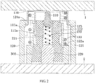
- FIG. 2 is a longitudinal cross-sectional view of the connector shown in FIG. 1 , in which a first electronic component 1 and a second electronic component 2 are shown.
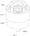
- FIG. 3 is a schematic perspective view showing a second outer contact 120 of the connector shown in FIG. 1 .
- FIG. 4 is a schematic perspective view showing a first outer contact 110 of the connector shown in FIG. 1 .
- the connector is used to electrically connect a first electronic component 1 with a second electronic component 2, as shown in FIG. 2 , and mainly includes outer contacts 110, 120, inner contacts 210, 220, and a first elastic element 130.
- the outer contacts 110, 120 include a first outer contact 110 and a second outer contact 120 which are slidably assembled together.
- the inner contacts 210, 220 are disposed within the outer contacts 110, 120, specifically, the inner contacts 210, 220 are provided in a longitudinal through-hole running through the outer contacts 110, 120.
- the inner contacts 210, 220 include a first inner contact 210 and a second inner contact 220 which are slidably assembled together.
- the first elastic element 130 is disposed between the first outer contact 110 and the second outer contact 120, and is adapted to exert an axial pushing force onto the first outer contact 110.
- the first outer contact 110 is in a reliable electrical contact with the first electronic component 1 under an action of the axial pushing force exerted by the first elastic element 130.
- the second outer contact 120 includes an outer cylinder 121 and an inner cylinder 122 connected to the outer cylinder 121.
- a receiving groove 123 having an annular cross section is defined between the outer cylinder 121 and the inner cylinder 122.
- the second outer contact 120 is integrally formed of metal by a casting process.
- the first outer contact 110 includes an elastic latch 111a and an elastic arm 112a.
- the elastic latch 111a is inserted into the receiving groove 123 and is adapted to be latched onto an inner wall of the outer cylinder 121.
- the elastic arm 112a is inserted into the inner cylinder 122 and is adapted to be in an elastically electrical contact with an inner wall of the inner cylinder 122.
- a blocking protrusion 121a is formed on the inner wall of the outer cylinder 121.
- the elastic latch 111a is adapted to be latched onto the blocking protrusion 121a to prevent the first outer contact 110 from moving outwardly relative to the second outer contact 120, thereby preventing the first outer contact 110 from disengaging from the second outer contact 120.
- the elastic latch 111a is an L-shaped elastic hook, and adapted to hook the blocking protrusion 121a.
- the first elastic element 130 is received in the receiving groove 123, one end of the first elastic element 130 abuts against the first outer contact 110 and the other end thereof abuts against the second outer contact 120.
- the first outer contact 110 further includes a base 113 to which the elastic latch 111a and the elastic arm 112a are coupled.
- One end (upper end in the figures) of the first elastic element 130 abuts against the base 113.
- a raised positioning step 122a is formed on an outer wall of the inner cylinder 122, and the other end (lower end in the figures) of the first elastic element 130 abuts against the positioning step 122a.
- the base 113 of the first outer contact 110 has an annular plate shape.
- the elastic latch 111a is coupled to an outer edge of the base 113, and the elastic arm 112a is coupled to an inner edge of the base 113.
- the first outer contact 110 includes a plurality of elastic latches 111a.
- the plurality of elastic latches 111a are evenly distributed around an outer circumference of the base 113.
- the first outer contact 110 includes a plurality of elastic arms 112a.
- the plurality of elastic arms 112a are evenly distributed around an inner circumference of the base 113.
- the connector further includes an insulator 300 disposed between the outer contacts 110, 120 and the inner contacts 210, 220.
- the insulator 300 is configured to hold the inner contacts 210, 220 within the outer contacts 110, 120 and to electrically isolate the inner contacts 210, 220 from the outer contacts 110, 120.
- the insulator 300 is housed in the inner cylinder 122 of the second outer contact 120, and the second inner contact 220 is held within the insulator 300.
- the first outer contact 110 is a single conductive element formed by stamping a single metal sheet.
- the connector further includes a second elastic element 230.
- the second elastic element 230 is disposed between the first inner contact 210 and the second inner contact 220, and is adapted to exert an axial pushing force onto the first inner contact 210.
- the first inner contact 210 is in a reliable electrical contact with the first electronic component 1 under an action of the axial pushing force exerted by the second elastic element 230.
- the second inner contact 220 has a cylindrical portion 221.
- An end of the first inner contact 210 is slidably inserted into the cylindrical portion 221 of the second inner contact 220, and is in a slidable electrical contact with the second inner contact 220.
- the inner contacts 210, 220 form a spring-like probe structure such as a pogo pin, and the second elastic element 230 is compressed by the first inner contact 210 in the cylindrical portion 221 of the second inner contact 220.
- the second outer contact 120 and the second inner contact 220 each have a flat bottom face which is adapted to be soldered onto the second electronic component 2.
- the present disclosure is not limited to the illustrated embodiment, the second outer contact 120 or the second inner contact 220 may be otherwise connected to the second electronic component 2, for example, the second outer contact 120 or the second center may be inserted into or screwed onto the second electronic component 2.
- the connector is a radio frequency (RF) coaxial connector which is adapted to be electrically connected between the first electronic component 1 and the second electronic component 2.
- RF radio frequency
- the first electronic component 1 and the second electronic component 2 are both circuit boards.
- the present disclosure is not limited to the illustrated embodiment, and the second electronic component 2 may be a filter.
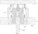
- FIG 5 is a schematic perspective view of a connector according to another exemplary embodiment of the present disclosure
- FIG. 6 is a longitudinal cross-sectional view of the connector shown in FIG. 5 .
- FIGS. 5-6 differs from the embodiment shown in FIGS. 1-4 mainly in the structure of the second inner contact 220 and the outer cylinder 121 of the second outer contact 120.
- an outer diameter of a lower end portion 121b of the outer cylinder 121 of the second outer contact 120 is smaller than an outer diameter of an upper end portion thereof.
- the lower end portion 121b of the outer cylinder 121 of the second outer contact 120 is adapted to be directly inserted into a socket on the second electronic component 2 (such as a filter).
- the second inner contact 220 has a plug portion 220b that projects outwardly from the second outer contact 120, and the plug portion 220b may be plugged into the socket on the second electronic component 2 (such as a filter).
- a threaded portion may be formed on an outer wall of the outer cylinder 121 of the second outer contact 120.
- the second outer contact 120 may be screwed onto the second electronic component 2 (such as a filter) by means of the threaded portion.
Landscapes
- Coupling Device And Connection With Printed Circuit (AREA)
- Details Of Connecting Devices For Male And Female Coupling (AREA)
Description
- The present disclosure relates to a coaxial connector, and more particularly to a radio frequency (RF) coaxial connector.
- In the related art, such as
US 2008/057782 A1 , disclosing the preamble ofclaim 1, andEP 1 289 076 A2 - In the related art, since the contact ring is latched onto an outer wall of the housing by the elastic latch, the elastic latch will expand outward when a large axial pushing force is applied to the contact ring, so that the elastic latch may be easily disengaged from the housing, thereby causing a disengagement of the contact ring from the housing.
- In addition, in an existing RF coaxial connector, the upper outer contact is a contact ring which is pressed by an external spring to ensure the electrical contact with the upper PCB. The external spring is usually exposed outside the connector and lacks suitable protection, as is the case with the coaxial connector disclosed in
EP 1 289 076 A2 -
Claim 1 discloses a coaxial connector according to the invention comprising: outer contacts including a first outer contact and a second outer contact which are slidably assembled together; inner contacts provided within the outer contacts; and a first elastic element disposed between the first outer contact and the second outer contact and adapted to exert an axial pushing force onto the first outer contact, wherein the second outer contact includes an outer cylinder and an inner cylinder connected to the outer cylinder, and a receiving groove having an annular cross section is defined between the outer cylinder and the inner cylinder; wherein the first elastic element is received in the receiving groove, and one end of the first elastic element abuts against the first outer contact and the other end thereof abuts against the second outer contact; and wherein the first outer contact includes an elastic latch which is adapted to be inserted into the receiving groove and be latched onto an inner wall of the outer cylinder. - Optionally, the first outer contact includes an elastic arm which is adapted to be inserted into the inner cylinder so as to be in an elastically electrical contact with the inner cylinder.
- Optionally, the inner contacts include a first inner contact and a second inner contact which are slidably assembled together.
- Optionally, the second outer contact is integrally cast from a metallic material.
- Optionally, a blocking protrusion is formed on the inner wall of the outer cylinder, and the elastic latch is adapted to be latched onto the blocking protrusion to prevent the first outer contact from moving outwardly relative to the second outer contact so as to prevent the first outer contact from disengaging from the second outer contact.
- Optionally, the elastic latch is an L-shaped elastic hook, and the elastic latch is adapted to hook the blocking protrusion.
- Optionally, the first outer contact further includes a base, to which the elastic latch and the elastic arm are coupled, and the one end of the first elastic element abuts against the base.
- Optionally, a raised positioning step is formed on an outer wall of the inner cylinder, and the other end of the first elastic element abuts against the positioning step.
- Optionally, the base of the first outer contact has an annular plate shape, the elastic latch is connected to an outer edge of the base, and the elastic arm is connected to an inner edge of the base.
- Optionally, the first outer contact includes a plurality of the elastic latches which are evenly distributed around an outer circumference of the base.
- Optionally, the first outer contact includes a plurality of the elastic arms which are evenly distributed around an inner circumference of the base.
- Optionally, the connector further includes an insulator which is disposed between the outer contacts and the inner contacts and configured to hold the inner contacts within the outer contacts and electrically isolate the inner contacts from the outer contacts.
- Optionally, the insulator is housed in the inner cylinder of the second outer contact, and the second inner contact is held within the insulator.
- Optionally, the first outer contact is a single conductive element formed by stamping a single metal sheet.
- Optionally, the connector further includes a second elastic element which is disposed between the first inner contact and the second inner contact and is adapted to exert an axial pushing force onto the first inner contact such that the first inner contact is in a reliable electrical contact with a first electronic component under an action of the axial pushing force exerted by the second elastic element.
- Optionally, the second inner contact has a cylindrical portion, and one end of the first inner contact is slidably inserted into the cylindrical portion of the second inner contact such that the first inner contact is in a slidable electrical contact with the second inner contact.
- Optionally, the inner contacts form a spring-like probe structure, and the second elastic element is compressed by the first inner contact in the cylindrical portion of the second inner contact.
- Optionally, the second outer contact or the second inner contact is adapted to be soldered onto, inserted into or screwed onto a second electronic component.
- Optionally, the second outer contact and the second inner contact each have a flat bottom face which is adapted to be soldered onto a second electronic component.
- Optionally, a threaded portion is formed on an outer wall of the outer cylinder of the second outer contact, and the second outer contact is adapted to be screwed onto a second electronic component by means of the threaded portion.
- Optionally, the connector is a radio frequency coaxial connector adapted to be electrically connected between a first electronic component and a second electronic component.
- Optionally, the first electronic component is a circuit board and the second electronic component is a circuit board or a filter.
-
-
FIG. 1 is a schematic perspective view of a coaxial connector according to the invention; -
FIG. 2 is a longitudinal cross-sectional view of the connector shown inFIG. 1 , in which a first electronic component and a second electronic component are shown; -
FIG. 3 is a schematic perspective view showing a second outer contact of the connector shown inFIG. 1 ; -
FIG. 4 is a schematic perspective view showing a first outer contact of the connector shown inFIG. 1 ; -
FIG. 5 is a schematic perspective view of a coaxial connector according to another exemplary embodiment of the present disclosure; and -
FIG. 6 is a longitudinal cross-sectional view of the connector shown inFIG. 5 . - Technical solutions of the present disclosure will be further specifically described below by reference to the embodiments of the present disclosure, taken in conjunction with the accompanying drawings. In the specification, the same or similar reference numerals indicate the same or similar elements. The description of the embodiments of the present disclosure with reference to the accompanying drawings is intended to illustrate the general inventive concept of the present disclosure, and should not be construed as limiting the invention.
- Moreover, in the following detailed description, for purposes of explanation, numerous specific details are set forth in order to provide a thorough understanding of the disclosed embodiments. It will be apparent, however, that one or more embodiments may be practiced without these specific details. In other instances, well-known structures and devices are schematically shown in order to simplify the drawing.
- According to the invention, there is provided a coaxial connector including: outer contacts including a first outer contact and a second outer which are slidably assembled together; inner contacts provided within the outer contacts; and a first elastic element provided between the first outer contact and the second outer contact and adapted to exert an axial pushing force onto the first outer contact. The second outer contact includes an outer cylinder and an inner cylinder connected to the outer cylinder, and a receiving groove having an annular cross section is defined between the outer cylinder and the inner cylinder. The first outer contact includes an elastic latch which is adapted to be inserted into the receiving groove and be latched onto an inner wall of the outer cylinder.
-
FIG. 1 is a schematic perspective view of a connector according to the invention.FIG. 2 is a longitudinal cross-sectional view of the connector shown inFIG. 1 , in which a firstelectronic component 1 and a secondelectronic component 2 are shown.FIG. 3 is a schematic perspective view showing a secondouter contact 120 of the connector shown inFIG. 1 .FIG. 4 is a schematic perspective view showing a firstouter contact 110 of the connector shown inFIG. 1 . - As shown in
FIGS. 1 to 4 , in the illustrated embodiment, the connector is used to electrically connect a firstelectronic component 1 with a secondelectronic component 2, as shown inFIG. 2 , and mainly includesouter contacts inner contacts elastic element 130. - As shown in
FIGS. 1 to 4 , in the illustrated embodiment, theouter contacts outer contact 110 and a secondouter contact 120 which are slidably assembled together. Theinner contacts outer contacts inner contacts outer contacts inner contacts inner contact 210 and a secondinner contact 220 which are slidably assembled together. - As shown in
FIGS. 1 to 4 , in the illustrated embodiment, the firstelastic element 130 is disposed between the firstouter contact 110 and the secondouter contact 120, and is adapted to exert an axial pushing force onto the firstouter contact 110. In this way, the firstouter contact 110 is in a reliable electrical contact with the firstelectronic component 1 under an action of the axial pushing force exerted by the firstelastic element 130. - As shown in
FIGS. 1 to 3 , in the illustrated embodiment, the secondouter contact 120 includes anouter cylinder 121 and aninner cylinder 122 connected to theouter cylinder 121. Areceiving groove 123 having an annular cross section is defined between theouter cylinder 121 and theinner cylinder 122. - According to an exemplary embodiment of the present disclosure, the second
outer contact 120 is integrally formed of metal by a casting process. - As shown in
FIGS. 1 to 4 , in the illustrated embodiment, the firstouter contact 110 includes anelastic latch 111a and anelastic arm 112a. Theelastic latch 111a is inserted into the receivinggroove 123 and is adapted to be latched onto an inner wall of theouter cylinder 121. Theelastic arm 112a is inserted into theinner cylinder 122 and is adapted to be in an elastically electrical contact with an inner wall of theinner cylinder 122. - As shown in
FIGS. 1 to 4 , in the illustrated embodiment, a blockingprotrusion 121a is formed on the inner wall of theouter cylinder 121. Theelastic latch 111a is adapted to be latched onto the blockingprotrusion 121a to prevent the firstouter contact 110 from moving outwardly relative to the secondouter contact 120, thereby preventing the firstouter contact 110 from disengaging from the secondouter contact 120. - As shown in
FIG. 1 to FIG. 4 , in the illustrated embodiment, theelastic latch 111a is an L-shaped elastic hook, and adapted to hook the blockingprotrusion 121a. - As shown in
FIGS. 1 to 4 , in the illustrated embodiment, the firstelastic element 130 is received in the receivinggroove 123, one end of the firstelastic element 130 abuts against the firstouter contact 110 and the other end thereof abuts against the secondouter contact 120. - As shown in
FIG. 1 to FIG. 4 , in the illustrated embodiment, the firstouter contact 110 further includes a base 113 to which theelastic latch 111a and theelastic arm 112a are coupled. One end (upper end in the figures) of the firstelastic element 130 abuts against thebase 113. - As shown in
FIGS. 1 to 4 , in the illustrated embodiment, a raisedpositioning step 122a is formed on an outer wall of theinner cylinder 122, and the other end (lower end in the figures) of the firstelastic element 130 abuts against thepositioning step 122a. - As shown in
FIGS. 1 to 4 , in the illustrated embodiment, thebase 113 of the firstouter contact 110 has an annular plate shape. Theelastic latch 111a is coupled to an outer edge of thebase 113, and theelastic arm 112a is coupled to an inner edge of thebase 113. - As shown in
FIGS. 1 to 4 , in the illustrated embodiment, the firstouter contact 110 includes a plurality ofelastic latches 111a. The plurality ofelastic latches 111a are evenly distributed around an outer circumference of thebase 113. - As shown in
FIGS. 1 to 4 , in the illustrated embodiment, the firstouter contact 110 includes a plurality ofelastic arms 112a. The plurality ofelastic arms 112a are evenly distributed around an inner circumference of thebase 113. - As shown in
FIGS. 1 to 4 , in the illustrated embodiment, the connector further includes aninsulator 300 disposed between theouter contacts inner contacts insulator 300 is configured to hold theinner contacts outer contacts inner contacts outer contacts - As shown in
FIGS. 1 to 4 , in the illustrated embodiment, theinsulator 300 is housed in theinner cylinder 122 of the secondouter contact 120, and the secondinner contact 220 is held within theinsulator 300. - As shown in
FIGS. 1 to 4 , in the illustrated embodiment, the firstouter contact 110 is a single conductive element formed by stamping a single metal sheet. - As shown in
FIGS. 1 to 4 , in the illustrated embodiment, the connector further includes a secondelastic element 230. The secondelastic element 230 is disposed between the firstinner contact 210 and the secondinner contact 220, and is adapted to exert an axial pushing force onto the firstinner contact 210. In this way, the firstinner contact 210 is in a reliable electrical contact with the firstelectronic component 1 under an action of the axial pushing force exerted by the secondelastic element 230. - As shown in
FIGS. 1 to 4 , in the illustrated embodiment, the secondinner contact 220 has acylindrical portion 221. An end of the firstinner contact 210 is slidably inserted into thecylindrical portion 221 of the secondinner contact 220, and is in a slidable electrical contact with the secondinner contact 220. - As shown in
FIGS. 1 to 4 , in the illustrated embodiment, theinner contacts elastic element 230 is compressed by the firstinner contact 210 in thecylindrical portion 221 of the secondinner contact 220. - As shown in
FIGS. 1 to 4 , in the illustrated embodiment, the secondouter contact 120 and the secondinner contact 220 each have a flat bottom face which is adapted to be soldered onto the secondelectronic component 2. - However, it should be noted that the present disclosure is not limited to the illustrated embodiment, the second
outer contact 120 or the secondinner contact 220 may be otherwise connected to the secondelectronic component 2, for example, the secondouter contact 120 or the second center may be inserted into or screwed onto the secondelectronic component 2. - As shown in
FIGS. 1 to 4 , in the illustrated embodiment, the connector is a radio frequency (RF) coaxial connector which is adapted to be electrically connected between the firstelectronic component 1 and the secondelectronic component 2. - As shown in
FIGS. 1 to 4 , in the illustrated embodiment, the firstelectronic component 1 and the secondelectronic component 2 are both circuit boards. - However, it should be noted that the present disclosure is not limited to the illustrated embodiment, and the second
electronic component 2 may be a filter. -
FIG 5 is a schematic perspective view of a connector according to another exemplary embodiment of the present disclosure, andFIG. 6 is a longitudinal cross-sectional view of the connector shown inFIG. 5 . - The embodiment shown in
FIGS. 5-6 differs from the embodiment shown inFIGS. 1-4 mainly in the structure of the secondinner contact 220 and theouter cylinder 121 of the secondouter contact 120. - In the embodiment shown in
FIGS. 5 and6 , an outer diameter of alower end portion 121b of theouter cylinder 121 of the secondouter contact 120 is smaller than an outer diameter of an upper end portion thereof. Thus, thelower end portion 121b of theouter cylinder 121 of the secondouter contact 120 is adapted to be directly inserted into a socket on the second electronic component 2 (such as a filter). - With continued reference to
FIGS. 5 and6 , in the illustrated embodiment, the secondinner contact 220 has aplug portion 220b that projects outwardly from the secondouter contact 120, and theplug portion 220b may be plugged into the socket on the second electronic component 2 (such as a filter). - It should be noted that the present disclosure is not limited to the illustrated embodiments. For example, in another embodiment of the present disclosure, a threaded portion may be formed on an outer wall of the
outer cylinder 121 of the secondouter contact 120. The secondouter contact 120 may be screwed onto the second electronic component 2 (such as a filter) by means of the threaded portion. - It will be understood by those skilled in the art that the embodiments described above are exemplary and may be modified by those skilled in the art, and the structures described in the various embodiments may be combined freely without any conflicts in structure or principle.
- Though the present disclosure has been described with reference to the accompanying drawings, the illustrated embodiments are intended to be illustrative of the preferred embodiments of the present disclosure, and should not be construed as limiting the invention.
- As used herein, an element recited in the singular and proceeded with the word "a" or "an" should be understood as not excluding plural of said elements or steps, unless such exclusion is explicitly stated. Furthermore, references to "one embodiment" of the present disclosure are not intended to be interpreted as excluding the existence of additional embodiments that also incorporate the recited features. Moreover, unless explicitly stated to the contrary, embodiments "including", "comprising" or "having" an element or a plurality of elements having a particular property may include additional such elements not having that property. In addition, any reference numerals in the claims should not be construed as limiting the scope of the invention.
Claims (14)
- A coaxial connector comprising:outer contacts (110, 120) comprising a first outer contact (110) and a second outer contact (120) which are slidably assembled together;inner contacts (210, 220) provided within the outer contacts (110, 120); anda first elastic element (130) disposed between the first outer contact (110) and the second outer contact (120) and adapted to exert an axial pushing force onto the first outer contact (110),wherein the second outer contact (120) comprises an outer cylinder (121) and an inner cylinder (122) connected to the outer cylinder (121), and a receiving groove (123) having an an nular cross section is defined between the outer cylinder (121) and the inner cylinder (122); wherein the first elastic element (130) is received in the receiving groove (123), and one end of the first elastic element (130) abuts against the first outer contact (110) and the other end thereof abuts against the second outer contact (120); characterized in thatthe first outer contact (110) comprises an elastic latch (111a) which is adapted to be inserted into the receiving groove (123) and be latched onto an inner wall of the outer cylinder (121).
- The coaxial connector of claim 1, wherein:
the first outer contact (110) comprises an elastic arm (112a) which is adapted to be inserted into the inner cylinder (122) so as to be in an elastically electrical contact with the inner cylinder (122). - The coaxial connector of claim 1 or 2, wherein:
the inner contacts (210, 220) comprise a first inner contact (210) and a second inner contact (220) which are slidably assembled together. - The coaxial connector of any one of claims 1 to 3, wherein:the first outer contact (110) is a single conductive element formed by stamping a single metal sheet, andthe second outer contact (120) is integrally cast from a metallic material.
- The coaxial connector of any one of claims 1 to 4, wherein:a blocking protrusion (121a) is formed on the inner wall of the outer cylinder (121), and the elastic latch (111a) is adapted to be latched onto the blocking protrusion (121a) to prevent the first outer contact (110) from moving outwardly relative to the second outer contact (120) so as to prevent the first outer contact (110) from disengaging from the second outer contact (120); the elastic latch (111a) is an L-shaped elastic hook, andthe elastic latch (111a) is adapted to hook the blocking protrusion (121a).
- The coaxial connector of any one of claims 2 to 5 wherein:the first outer contact (110) further comprises a base (113), to which the elastic latch (111a) and the elastic arm (112a) are coupled, and the one end of the first elastic element (130) abuts against the base (113); anda raised positioning step (122a) is formed on an outer wall of the inner cylinder (122), and the other end of the first elastic element (130) abuts against the positioning step (122a).
- The coaxial connector of claim 6, wherein:
the base (113) of the first outer contact (110) has an annular plate shape, the elastic latch (111a) is connected to an outer edge of the base (113), and the elastic arm (112a) is connected to an inner edge of the base (113). - The coaxial connector of claim 7, wherein:
the first outer contact (110) comprises a plurality of the elastic latches (111a) which are evenly distributed around an outer circumference of the base (113); and the first outer contact (110) comprises a plurality of the elastic arms (112a) which are evenly distributed around an inner circumference of the base (113). - The coaxial connector of any one of claims 1 to 8, wherein:the connector further comprises an insulator (300) which is disposed between the outer contacts (110, 120) and the inner contacts (210, 220) and configured to hold the inner contacts (210, 220) within the outer contacts (110, 120) and electrically isolate the inner contacts (210, 220) from the outer contacts (110, 120); andthe insulator (300) is housed in the inner cylinder (122) of the second outer contact (120), and the second inner contact (220) is held within the insulator (300).
- The coaxial connector of claim 3, or claim 3 and any one of claims 4 to 9, wherein:
the connector further comprises a second elastic element (230) which is disposed between the first inner contact (210) and the second inner contact (220) and is adapted to exert an axial pushing force onto the first inner contact (210) such that the first inner contact (210) is in a reliable electrical contact with a first electronic component (1) under an action of the axial pushing force exerted by the second elastic element (230). - The coaxial connector of claim 10, wherein:the second inner contact (220) has a cylindrical portion (221), and one end of the first inner contact (210) is slidably inserted into the cylindrical portion (221) of the second inner contact (220) such that the first inner contact (210) is in a slidable electrical contact with the second inner contact (220); andthe inner contacts (210, 220) form a spring-like probe structure, and the second elastic element (230) is compressed by the first inner contact (210) in the cylindrical portion (221) of the second inner contact (220).
- The coaxial connector of claim 3, or claim 3 and any one of claims 4 to 11, wherein:
the second outer contact (120) or the second inner contact (220) is adapted to be soldered onto, inserted into or screwed onto a second electronic component (2). - The coaxial connector of claim 12, wherein:
the second outer contact (120) and the second inner contact (220) each have a flat bottom face which is adapted to be soldered onto a second electronic component (2), or a threaded portion is formed on an outer wall of the outer cylinder (121) of the second outer contact (120), and the second outer contact (120) is adapted to be screwed onto a second electronic component (2) by means of the threaded portion. - The coaxial connector of any one of claims 1 to 13 wherein:the coaxial connector is a radio frequency coaxial connector adapted to be electrically connected between a first electronic component (1) and a second electronic component (2); andthe first electronic component (1) is a circuit board and the second electronic component (2) is a circuit board or a filter.
Applications Claiming Priority (1)
| Application Number | Priority Date | Filing Date | Title |
|---|---|---|---|
| CN201810291330.9A CN110323616A (en) | 2018-03-30 | 2018-03-30 | Connector |
Publications (2)
| Publication Number | Publication Date |
|---|---|
| EP3550669A1 EP3550669A1 (en) | 2019-10-09 |
| EP3550669B1 true EP3550669B1 (en) | 2021-10-20 |
Family
ID=65904263
Family Applications (1)
| Application Number | Title | Priority Date | Filing Date |
|---|---|---|---|
| EP19164496.2A Active EP3550669B1 (en) | 2018-03-30 | 2019-03-22 | Coaxial connector |
Country Status (3)
| Country | Link |
|---|---|
| US (1) | US10790624B2 (en) |
| EP (1) | EP3550669B1 (en) |
| CN (1) | CN110323616A (en) |
Families Citing this family (10)
| Publication number | Priority date | Publication date | Assignee | Title |
|---|---|---|---|---|
| CN111509446A (en) * | 2019-01-31 | 2020-08-07 | 泰科电子(上海)有限公司 | Connector with a locking member |
| US20220181826A1 (en) * | 2019-03-11 | 2022-06-09 | Samtec, Inc. | Impedance controlled electrical contact |
| CN110011136B (en) * | 2019-03-11 | 2020-09-25 | 番禺得意精密电子工业有限公司 | Connector assembly |
| CN112421278A (en) * | 2019-08-23 | 2021-02-26 | 泰科电子(上海)有限公司 | Electrical connector and electrical connector assembly |
| CN112787121A (en) * | 2019-11-11 | 2021-05-11 | 康普技术有限责任公司 | Coaxial connector and board-to-board connector assembly |
| KR20210083814A (en) | 2019-12-27 | 2021-07-07 | 주식회사 기가레인 | Board mating connector |
| US11515669B2 (en) * | 2020-03-11 | 2022-11-29 | Te Connectivity Solutions Gmbh | Floating header and circuit board assembly |
| DE102020210534B4 (en) | 2020-04-30 | 2023-03-23 | Te Connectivity Germany Gmbh | CONTACT SYSTEM |
| JP7280558B2 (en) * | 2020-10-12 | 2023-05-24 | Smk株式会社 | Floating structure of coaxial connector |
| EP4264745A1 (en) | 2021-01-14 | 2023-10-25 | Rosenberger Hochfrequenztechnik Gmbh & Co. Kg | Electrical plug-in connection and printed circuit board arrangement |
Family Cites Families (24)
| Publication number | Priority date | Publication date | Assignee | Title |
|---|---|---|---|---|
| FR2715004B1 (en) * | 1994-01-13 | 1996-03-01 | Radiall Sa | Microminiature coaxial connector with snap lock. |
| US5516303A (en) * | 1995-01-11 | 1996-05-14 | The Whitaker Corporation | Floating panel-mounted coaxial connector for use with stripline circuit boards |
| JP3127287B2 (en) * | 1996-07-12 | 2001-01-22 | 日本航空電子工業株式会社 | Coaxial connector device |
| JP3546180B2 (en) * | 2000-12-27 | 2004-07-21 | 日本圧着端子製造株式会社 | Communication module connector and communication module connection structure |
| EP1289076B1 (en) * | 2001-08-31 | 2005-06-15 | Tyco Electronics AMP GmbH | Coaxial connector for interconnecting printed circuit boards |
| US6776668B1 (en) * | 2003-08-01 | 2004-08-17 | Tyco Electronics Corporation | Low profile coaxial board-to-board connector |
| FR2905528B1 (en) * | 2006-08-31 | 2008-10-31 | Radiall Sa | COAXIAL CONNECTOR FOR CONNECTING TWO CIRCUIT BOARDS. |
| JP4450242B2 (en) * | 2007-04-10 | 2010-04-14 | ヒロセ電機株式会社 | Coaxial connector |
| CN101420091B (en) * | 2008-11-25 | 2011-11-23 | 上海雷迪埃电子有限公司 | High-frequency coaxial connector |
| US7887365B1 (en) * | 2009-07-22 | 2011-02-15 | Tyco Electronics Corporation | Electrical plug and jack assembly |
| JP5340107B2 (en) * | 2009-10-13 | 2013-11-13 | 日本圧着端子製造株式会社 | Coaxial connector and coaxial connector with antenna |
| US7922529B1 (en) * | 2009-11-23 | 2011-04-12 | Neocoil, Llc | High mating cycle low insertion force coaxial connector |
| US7972173B1 (en) * | 2010-05-07 | 2011-07-05 | Itt Manufacturing Enterprises, Inc. | Dual spring probe coaxial contact system |
| US9147955B2 (en) * | 2011-11-02 | 2015-09-29 | Ppc Broadband, Inc. | Continuity providing port |
| DE202012010365U1 (en) * | 2012-10-29 | 2012-11-13 | Rosenberger Hochfrequenztechnik Gmbh & Co. Kg | Contact element and contact device |
| CN103094782B (en) * | 2013-02-21 | 2015-04-01 | 上海航天科工电器研究院有限公司 | Radio frequency coaxial electric coupler with quick-locking device |
| CN104577370A (en) * | 2013-10-15 | 2015-04-29 | 禾昌兴业电子(深圳)有限公司 | Cable connector assembly |
| TWM482874U (en) * | 2014-04-01 | 2014-07-21 | Insert Entpr Co Ltd | RF pass through connector |
| JP5872000B1 (en) * | 2014-08-06 | 2016-03-01 | 日本航空電子工業株式会社 | Coaxial connector |
| DE202015007010U1 (en) * | 2015-10-07 | 2015-10-22 | Rosenberger Hochfrequenztechnik Gmbh & Co. Kg | Interconnects |
| CN206412597U (en) * | 2016-11-03 | 2017-08-15 | 泰科电子(上海)有限公司 | adapter, socket and connector combination |
| CN206412585U (en) * | 2016-11-03 | 2017-08-15 | 泰科电子(上海)有限公司 | adapter, socket and connector combination |
| US10069257B1 (en) * | 2017-09-06 | 2018-09-04 | Carlisle Interconnect Technologies, Inc. | Inline compression RF connector |
| CN208608422U (en) * | 2018-03-30 | 2019-03-15 | 泰科电子(上海)有限公司 | Connector |
-
2018
- 2018-03-30 CN CN201810291330.9A patent/CN110323616A/en active Pending
-
2019
- 2019-03-22 EP EP19164496.2A patent/EP3550669B1/en active Active
- 2019-03-27 US US16/365,806 patent/US10790624B2/en active Active
Also Published As
| Publication number | Publication date |
|---|---|
| EP3550669A1 (en) | 2019-10-09 |
| US20190305495A1 (en) | 2019-10-03 |
| US10790624B2 (en) | 2020-09-29 |
| CN110323616A (en) | 2019-10-11 |
Similar Documents
| Publication | Publication Date | Title |
|---|---|---|
| EP3550669B1 (en) | Coaxial connector | |
| EP3537546B1 (en) | Connector | |
| US4718854A (en) | Low profile press fit connector | |
| EP3691043A1 (en) | Connector | |
| EP3671968A2 (en) | Electrical connector housing, electrical connector and electrical connector assembly | |
| US10931051B2 (en) | Connector and receptacle | |
| JP3027570B1 (en) | Connector structure | |
| US20180301830A1 (en) | Float connector for interconnecting printed circuit boards | |
| TW201607186A (en) | Coaxial connector | |
| EP3783743A1 (en) | Electrical connector and electrical connector assembly | |
| US10199753B2 (en) | Multi-pin connector block assembly | |
| US10840646B2 (en) | Anti-misplug coaxial connector assembly | |
| US6139349A (en) | Electrical connector with tactile feedback | |
| CN110323608A (en) | The pedestal of connector mould group and connector mould group | |
| TWI834751B (en) | Rf connector | |
| EP3206266B1 (en) | Push on connector | |
| US10389045B2 (en) | Electrical coaxial connector | |
| CN210723463U (en) | Electrical component | |
| CN111916941A (en) | Connector with a locking member | |
| CN210052884U (en) | Connector with a locking member | |
| CN215934000U (en) | Radio frequency coaxial line and electronic equipment | |
| WO2018200116A1 (en) | Radio frequency (rf) connector pin assembly | |
| CN111653909A (en) | Connector with a locking member | |
| CN211530232U (en) | Electrical connector and electrical connector assembly |
Legal Events
| Date | Code | Title | Description |
|---|---|---|---|
| PUAI | Public reference made under article 153(3) epc to a published international application that has entered the european phase |
Free format text: ORIGINAL CODE: 0009012 |
|
| STAA | Information on the status of an ep patent application or granted ep patent |
Free format text: STATUS: THE APPLICATION HAS BEEN PUBLISHED |
|
| AK | Designated contracting states |
Kind code of ref document: A1 Designated state(s): AL AT BE BG CH CY CZ DE DK EE ES FI FR GB GR HR HU IE IS IT LI LT LU LV MC MK MT NL NO PL PT RO RS SE SI SK SM TR |
|
| AX | Request for extension of the european patent |
Extension state: BA ME |
|
| STAA | Information on the status of an ep patent application or granted ep patent |
Free format text: STATUS: REQUEST FOR EXAMINATION WAS MADE |
|
| 17P | Request for examination filed |
Effective date: 20200325 |
|
| RBV | Designated contracting states (corrected) |
Designated state(s): AL AT BE BG CH CY CZ DE DK EE ES FI FR GB GR HR HU IE IS IT LI LT LU LV MC MK MT NL NO PL PT RO RS SE SI SK SM TR |
|
| REG | Reference to a national code |
Ref country code: DE Ref legal event code: R079 Ref document number: 602019008424 Country of ref document: DE Free format text: PREVIOUS MAIN CLASS: H01R0012710000 Ipc: H01R0013240000 |
|
| GRAP | Despatch of communication of intention to grant a patent |
Free format text: ORIGINAL CODE: EPIDOSNIGR1 |
|
| STAA | Information on the status of an ep patent application or granted ep patent |
Free format text: STATUS: GRANT OF PATENT IS INTENDED |
|
| RIC1 | Information provided on ipc code assigned before grant |
Ipc: H01R 24/50 20110101ALI20210414BHEP Ipc: H01R 12/73 20110101ALI20210414BHEP Ipc: H01R 12/71 20110101ALI20210414BHEP Ipc: H01R 13/24 20060101AFI20210414BHEP |
|
| RIC1 | Information provided on ipc code assigned before grant |
Ipc: H01R 12/91 20110101ALI20210416BHEP Ipc: H01R 24/50 20110101ALI20210416BHEP Ipc: H01R 12/73 20110101ALI20210416BHEP Ipc: H01R 12/71 20110101ALI20210416BHEP Ipc: H01R 13/24 20060101AFI20210416BHEP |
|
| INTG | Intention to grant announced |
Effective date: 20210504 |
|
| GRAS | Grant fee paid |
Free format text: ORIGINAL CODE: EPIDOSNIGR3 |
|
| GRAA | (expected) grant |
Free format text: ORIGINAL CODE: 0009210 |
|
| STAA | Information on the status of an ep patent application or granted ep patent |
Free format text: STATUS: THE PATENT HAS BEEN GRANTED |
|
| AK | Designated contracting states |
Kind code of ref document: B1 Designated state(s): AL AT BE BG CH CY CZ DE DK EE ES FI FR GB GR HR HU IE IS IT LI LT LU LV MC MK MT NL NO PL PT RO RS SE SI SK SM TR |
|
| REG | Reference to a national code |
Ref country code: GB Ref legal event code: FG4D |
|
| REG | Reference to a national code |
Ref country code: CH Ref legal event code: EP |
|
| REG | Reference to a national code |
Ref country code: IE Ref legal event code: FG4D |
|
| REG | Reference to a national code |
Ref country code: DE Ref legal event code: R096 Ref document number: 602019008424 Country of ref document: DE |
|
| REG | Reference to a national code |
Ref country code: AT Ref legal event code: REF Ref document number: 1440690 Country of ref document: AT Kind code of ref document: T Effective date: 20211115 |
|
| REG | Reference to a national code |
Ref country code: SE Ref legal event code: TRGR |
|
| REG | Reference to a national code |
Ref country code: LT Ref legal event code: MG9D |
|
| REG | Reference to a national code |
Ref country code: NL Ref legal event code: MP Effective date: 20211020 |
|
| REG | Reference to a national code |
Ref country code: AT Ref legal event code: MK05 Ref document number: 1440690 Country of ref document: AT Kind code of ref document: T Effective date: 20211020 |
|
| PG25 | Lapsed in a contracting state [announced via postgrant information from national office to epo] |
Ref country code: RS Free format text: LAPSE BECAUSE OF FAILURE TO SUBMIT A TRANSLATION OF THE DESCRIPTION OR TO PAY THE FEE WITHIN THE PRESCRIBED TIME-LIMIT Effective date: 20211020 Ref country code: LT Free format text: LAPSE BECAUSE OF FAILURE TO SUBMIT A TRANSLATION OF THE DESCRIPTION OR TO PAY THE FEE WITHIN THE PRESCRIBED TIME-LIMIT Effective date: 20211020 Ref country code: FI Free format text: LAPSE BECAUSE OF FAILURE TO SUBMIT A TRANSLATION OF THE DESCRIPTION OR TO PAY THE FEE WITHIN THE PRESCRIBED TIME-LIMIT Effective date: 20211020 Ref country code: BG Free format text: LAPSE BECAUSE OF FAILURE TO SUBMIT A TRANSLATION OF THE DESCRIPTION OR TO PAY THE FEE WITHIN THE PRESCRIBED TIME-LIMIT Effective date: 20220120 Ref country code: AT Free format text: LAPSE BECAUSE OF FAILURE TO SUBMIT A TRANSLATION OF THE DESCRIPTION OR TO PAY THE FEE WITHIN THE PRESCRIBED TIME-LIMIT Effective date: 20211020 |
|
| PG25 | Lapsed in a contracting state [announced via postgrant information from national office to epo] |
Ref country code: IS Free format text: LAPSE BECAUSE OF FAILURE TO SUBMIT A TRANSLATION OF THE DESCRIPTION OR TO PAY THE FEE WITHIN THE PRESCRIBED TIME-LIMIT Effective date: 20220220 Ref country code: PT Free format text: LAPSE BECAUSE OF FAILURE TO SUBMIT A TRANSLATION OF THE DESCRIPTION OR TO PAY THE FEE WITHIN THE PRESCRIBED TIME-LIMIT Effective date: 20220221 Ref country code: PL Free format text: LAPSE BECAUSE OF FAILURE TO SUBMIT A TRANSLATION OF THE DESCRIPTION OR TO PAY THE FEE WITHIN THE PRESCRIBED TIME-LIMIT Effective date: 20211020 Ref country code: NO Free format text: LAPSE BECAUSE OF FAILURE TO SUBMIT A TRANSLATION OF THE DESCRIPTION OR TO PAY THE FEE WITHIN THE PRESCRIBED TIME-LIMIT Effective date: 20220120 Ref country code: NL Free format text: LAPSE BECAUSE OF FAILURE TO SUBMIT A TRANSLATION OF THE DESCRIPTION OR TO PAY THE FEE WITHIN THE PRESCRIBED TIME-LIMIT Effective date: 20211020 Ref country code: LV Free format text: LAPSE BECAUSE OF FAILURE TO SUBMIT A TRANSLATION OF THE DESCRIPTION OR TO PAY THE FEE WITHIN THE PRESCRIBED TIME-LIMIT Effective date: 20211020 Ref country code: HR Free format text: LAPSE BECAUSE OF FAILURE TO SUBMIT A TRANSLATION OF THE DESCRIPTION OR TO PAY THE FEE WITHIN THE PRESCRIBED TIME-LIMIT Effective date: 20211020 Ref country code: GR Free format text: LAPSE BECAUSE OF FAILURE TO SUBMIT A TRANSLATION OF THE DESCRIPTION OR TO PAY THE FEE WITHIN THE PRESCRIBED TIME-LIMIT Effective date: 20220121 Ref country code: ES Free format text: LAPSE BECAUSE OF FAILURE TO SUBMIT A TRANSLATION OF THE DESCRIPTION OR TO PAY THE FEE WITHIN THE PRESCRIBED TIME-LIMIT Effective date: 20211020 |
|
| REG | Reference to a national code |
Ref country code: DE Ref legal event code: R097 Ref document number: 602019008424 Country of ref document: DE |
|
| PG25 | Lapsed in a contracting state [announced via postgrant information from national office to epo] |
Ref country code: SM Free format text: LAPSE BECAUSE OF FAILURE TO SUBMIT A TRANSLATION OF THE DESCRIPTION OR TO PAY THE FEE WITHIN THE PRESCRIBED TIME-LIMIT Effective date: 20211020 Ref country code: SK Free format text: LAPSE BECAUSE OF FAILURE TO SUBMIT A TRANSLATION OF THE DESCRIPTION OR TO PAY THE FEE WITHIN THE PRESCRIBED TIME-LIMIT Effective date: 20211020 Ref country code: RO Free format text: LAPSE BECAUSE OF FAILURE TO SUBMIT A TRANSLATION OF THE DESCRIPTION OR TO PAY THE FEE WITHIN THE PRESCRIBED TIME-LIMIT Effective date: 20211020 Ref country code: EE Free format text: LAPSE BECAUSE OF FAILURE TO SUBMIT A TRANSLATION OF THE DESCRIPTION OR TO PAY THE FEE WITHIN THE PRESCRIBED TIME-LIMIT Effective date: 20211020 Ref country code: DK Free format text: LAPSE BECAUSE OF FAILURE TO SUBMIT A TRANSLATION OF THE DESCRIPTION OR TO PAY THE FEE WITHIN THE PRESCRIBED TIME-LIMIT Effective date: 20211020 Ref country code: CZ Free format text: LAPSE BECAUSE OF FAILURE TO SUBMIT A TRANSLATION OF THE DESCRIPTION OR TO PAY THE FEE WITHIN THE PRESCRIBED TIME-LIMIT Effective date: 20211020 |
|
| PLBE | No opposition filed within time limit |
Free format text: ORIGINAL CODE: 0009261 |
|
| STAA | Information on the status of an ep patent application or granted ep patent |
Free format text: STATUS: NO OPPOSITION FILED WITHIN TIME LIMIT |
|
| 26N | No opposition filed |
Effective date: 20220721 |
|
| PG25 | Lapsed in a contracting state [announced via postgrant information from national office to epo] |
Ref country code: MC Free format text: LAPSE BECAUSE OF FAILURE TO SUBMIT A TRANSLATION OF THE DESCRIPTION OR TO PAY THE FEE WITHIN THE PRESCRIBED TIME-LIMIT Effective date: 20211020 Ref country code: AL Free format text: LAPSE BECAUSE OF FAILURE TO SUBMIT A TRANSLATION OF THE DESCRIPTION OR TO PAY THE FEE WITHIN THE PRESCRIBED TIME-LIMIT Effective date: 20211020 |
|
| REG | Reference to a national code |
Ref country code: CH Ref legal event code: PL |
|
| PG25 | Lapsed in a contracting state [announced via postgrant information from national office to epo] |
Ref country code: SI Free format text: LAPSE BECAUSE OF FAILURE TO SUBMIT A TRANSLATION OF THE DESCRIPTION OR TO PAY THE FEE WITHIN THE PRESCRIBED TIME-LIMIT Effective date: 20211020 |
|
| REG | Reference to a national code |
Ref country code: BE Ref legal event code: MM Effective date: 20220331 |
|
| PG25 | Lapsed in a contracting state [announced via postgrant information from national office to epo] |
Ref country code: LU Free format text: LAPSE BECAUSE OF NON-PAYMENT OF DUE FEES Effective date: 20220322 Ref country code: LI Free format text: LAPSE BECAUSE OF NON-PAYMENT OF DUE FEES Effective date: 20220331 Ref country code: IE Free format text: LAPSE BECAUSE OF NON-PAYMENT OF DUE FEES Effective date: 20220322 Ref country code: FR Free format text: LAPSE BECAUSE OF NON-PAYMENT OF DUE FEES Effective date: 20220331 Ref country code: CH Free format text: LAPSE BECAUSE OF NON-PAYMENT OF DUE FEES Effective date: 20220331 |
|
| PG25 | Lapsed in a contracting state [announced via postgrant information from national office to epo] |
Ref country code: BE Free format text: LAPSE BECAUSE OF NON-PAYMENT OF DUE FEES Effective date: 20220331 |
|
| PG25 | Lapsed in a contracting state [announced via postgrant information from national office to epo] |
Ref country code: IT Free format text: LAPSE BECAUSE OF FAILURE TO SUBMIT A TRANSLATION OF THE DESCRIPTION OR TO PAY THE FEE WITHIN THE PRESCRIBED TIME-LIMIT Effective date: 20211020 |
|
| GBPC | Gb: european patent ceased through non-payment of renewal fee |
Effective date: 20230322 |
|
| PG25 | Lapsed in a contracting state [announced via postgrant information from national office to epo] |
Ref country code: GB Free format text: LAPSE BECAUSE OF NON-PAYMENT OF DUE FEES Effective date: 20230322 |
|
| PG25 | Lapsed in a contracting state [announced via postgrant information from national office to epo] |
Ref country code: GB Free format text: LAPSE BECAUSE OF NON-PAYMENT OF DUE FEES Effective date: 20230322 |
|
| PG25 | Lapsed in a contracting state [announced via postgrant information from national office to epo] |
Ref country code: MK Free format text: LAPSE BECAUSE OF FAILURE TO SUBMIT A TRANSLATION OF THE DESCRIPTION OR TO PAY THE FEE WITHIN THE PRESCRIBED TIME-LIMIT Effective date: 20211020 Ref country code: CY Free format text: LAPSE BECAUSE OF FAILURE TO SUBMIT A TRANSLATION OF THE DESCRIPTION OR TO PAY THE FEE WITHIN THE PRESCRIBED TIME-LIMIT Effective date: 20211020 |
|
| PGFP | Annual fee paid to national office [announced via postgrant information from national office to epo] |
Ref country code: DE Payment date: 20231229 Year of fee payment: 6 |
|
| PG25 | Lapsed in a contracting state [announced via postgrant information from national office to epo] |
Ref country code: HU Free format text: LAPSE BECAUSE OF FAILURE TO SUBMIT A TRANSLATION OF THE DESCRIPTION OR TO PAY THE FEE WITHIN THE PRESCRIBED TIME-LIMIT; INVALID AB INITIO Effective date: 20190322 |
|
| PGFP | Annual fee paid to national office [announced via postgrant information from national office to epo] |
Ref country code: SE Payment date: 20240103 Year of fee payment: 6 |