EP3671799A1 - Nullleiterschutzschalter mit doppelunterbrechung und netzseitiggespeister elektronischer platine - Google Patents
Nullleiterschutzschalter mit doppelunterbrechung und netzseitiggespeister elektronischer platine Download PDFInfo
- Publication number
- EP3671799A1 EP3671799A1 EP19213943.4A EP19213943A EP3671799A1 EP 3671799 A1 EP3671799 A1 EP 3671799A1 EP 19213943 A EP19213943 A EP 19213943A EP 3671799 A1 EP3671799 A1 EP 3671799A1
- Authority
- EP
- European Patent Office
- Prior art keywords
- moveable
- circuit breaker
- contacts
- stationary
- circuit
- Prior art date
- Legal status (The legal status is an assumption and is not a legal conclusion. Google has not performed a legal analysis and makes no representation as to the accuracy of the status listed.)
- Granted
Links
- 230000007935 neutral effect Effects 0.000 title claims abstract description 52
- 230000035939 shock Effects 0.000 claims description 7
- 238000010586 diagram Methods 0.000 description 6
- 238000010304 firing Methods 0.000 description 2
- 230000004888 barrier function Effects 0.000 description 1
- 238000002955 isolation Methods 0.000 description 1
- 230000002459 sustained effect Effects 0.000 description 1
Images


Classifications
-
- H—ELECTRICITY
- H01—ELECTRIC ELEMENTS
- H01H—ELECTRIC SWITCHES; RELAYS; SELECTORS; EMERGENCY PROTECTIVE DEVICES
- H01H71/00—Details of the protective switches or relays covered by groups H01H73/00 - H01H83/00
- H01H71/10—Operating or release mechanisms
- H01H71/12—Automatic release mechanisms with or without manual release
- H01H71/123—Automatic release mechanisms with or without manual release using a solid-state trip unit
-
- H—ELECTRICITY
- H01—ELECTRIC ELEMENTS
- H01H—ELECTRIC SWITCHES; RELAYS; SELECTORS; EMERGENCY PROTECTIVE DEVICES
- H01H71/00—Details of the protective switches or relays covered by groups H01H73/00 - H01H83/00
- H01H71/10—Operating or release mechanisms
- H01H71/12—Automatic release mechanisms with or without manual release
-
- H—ELECTRICITY
- H01—ELECTRIC ELEMENTS
- H01H—ELECTRIC SWITCHES; RELAYS; SELECTORS; EMERGENCY PROTECTIVE DEVICES
- H01H71/00—Details of the protective switches or relays covered by groups H01H73/00 - H01H83/00
- H01H71/002—Details of the protective switches or relays covered by groups H01H73/00 - H01H83/00 with provision for switching the neutral conductor
-
- H—ELECTRICITY
- H01—ELECTRIC ELEMENTS
- H01H—ELECTRIC SWITCHES; RELAYS; SELECTORS; EMERGENCY PROTECTIVE DEVICES
- H01H71/00—Details of the protective switches or relays covered by groups H01H73/00 - H01H83/00
- H01H71/02—Housings; Casings; Bases; Mountings
- H01H71/0207—Mounting or assembling the different parts of the circuit breaker
-
- H—ELECTRICITY
- H01—ELECTRIC ELEMENTS
- H01H—ELECTRIC SWITCHES; RELAYS; SELECTORS; EMERGENCY PROTECTIVE DEVICES
- H01H71/00—Details of the protective switches or relays covered by groups H01H73/00 - H01H83/00
- H01H71/04—Means for indicating condition of the switching device
-
- H—ELECTRICITY
- H01—ELECTRIC ELEMENTS
- H01H—ELECTRIC SWITCHES; RELAYS; SELECTORS; EMERGENCY PROTECTIVE DEVICES
- H01H71/00—Details of the protective switches or relays covered by groups H01H73/00 - H01H83/00
- H01H71/10—Operating or release mechanisms
- H01H71/12—Automatic release mechanisms with or without manual release
- H01H71/46—Automatic release mechanisms with or without manual release having means for operating auxiliary contacts additional to the main contacts
-
- H—ELECTRICITY
- H01—ELECTRIC ELEMENTS
- H01H—ELECTRIC SWITCHES; RELAYS; SELECTORS; EMERGENCY PROTECTIVE DEVICES
- H01H83/00—Protective switches, e.g. circuit-breaking switches, or protective relays operated by abnormal electrical conditions otherwise than solely by excess current
- H01H83/20—Protective switches, e.g. circuit-breaking switches, or protective relays operated by abnormal electrical conditions otherwise than solely by excess current operated by excess current as well as by some other abnormal electrical condition
-
- H—ELECTRICITY
- H01—ELECTRIC ELEMENTS
- H01H—ELECTRIC SWITCHES; RELAYS; SELECTORS; EMERGENCY PROTECTIVE DEVICES
- H01H71/00—Details of the protective switches or relays covered by groups H01H73/00 - H01H83/00
- H01H2071/006—Provisions for user interfaces for electrical protection devices
-
- H—ELECTRICITY
- H01—ELECTRIC ELEMENTS
- H01H—ELECTRIC SWITCHES; RELAYS; SELECTORS; EMERGENCY PROTECTIVE DEVICES
- H01H71/00—Details of the protective switches or relays covered by groups H01H73/00 - H01H83/00
- H01H71/04—Means for indicating condition of the switching device
- H01H2071/042—Means for indicating condition of the switching device with different indications for different conditions, e.g. contact position, overload, short circuit or earth leakage
-
- H—ELECTRICITY
- H01—ELECTRIC ELEMENTS
- H01H—ELECTRIC SWITCHES; RELAYS; SELECTORS; EMERGENCY PROTECTIVE DEVICES
- H01H83/00—Protective switches, e.g. circuit-breaking switches, or protective relays operated by abnormal electrical conditions otherwise than solely by excess current
- H01H83/20—Protective switches, e.g. circuit-breaking switches, or protective relays operated by abnormal electrical conditions otherwise than solely by excess current operated by excess current as well as by some other abnormal electrical condition
- H01H2083/201—Protective switches, e.g. circuit-breaking switches, or protective relays operated by abnormal electrical conditions otherwise than solely by excess current operated by excess current as well as by some other abnormal electrical condition the other abnormal electrical condition being an arc fault
Definitions
- the invention disclosed relates to circuit breakers.
- Miniature circuit breakers are well known in the prior art.
- An illustrative circuit breaker design is disclosed in U.S. Pat. No. 5,245,302 , which is assigned to the same assignee as the present application, and the disclosure in which is incorporated herein by reference.
- the basic miniature automatic circuit breaker comprises a base and cover, a line power terminal, a load power terminal, and an electrical circuit between the line terminal and a load terminal.
- the electrical circuit includes a stationary contact and a movable contact secured to a contact carrier, which is movable between a contact OPEN position and a contact CLOSED position to open or close the electrical circuit.
- the circuit breaker includes an arc interrupting chamber, an operating mechanism for opening and closing the contacts, and a current responsive trip mechanism, which releases the operating mechanism to open the contacts in response to a sustained moderate overload or an instantaneous short circuit.
- Modern miniature circuit breakers incorporate light emitting diodes (LEDs) to enable users to easily identify the trip condition and type of fault, for example an arc fault or ground fault.
- the circuit for the LEDs is powered from the line power side, to ensure that the LEDs remain lit when the circuit breaker is tripped.
- an electrical shock hazard may occur if the neutral terminal of the circuit breaker is inadvertently disconnected, causing power from the line power side to flow through the circuit for the LEDs and be present on the load neutral terminal of the circuit breaker.
- the invention provides a simple, safe, practical and easily manufactured miniature circuit breaker, which provides power from the line power side to the electronics board or printed circuit board assembly (PCBA), while preventing an electrical shock hazard if the neutral terminal of the circuit breaker is inadvertently disconnected.
- the PCBA may provide power to LEDS or power other functions, such as denial of service solenoids or internal communications hardware, such as radio transmitters and receivers.
- the circuit breaker includes separate contact pairs for the line power terminal to load power terminal circuit path and for the neutral terminal to load neutral terminal circuit path, and both contact pairs are simultaneously opened and closed in unison.
- the PCBA is directly connected across the line power terminal and the neutral terminal and remains connected when both pairs of contacts are opened. However, when both pairs of contacts are opened, both line power and neutral circuit paths are interrupted from connection to the load power and load neutral terminals, to prevent power from the line power side to flow through the circuit for the PCBA and be present on the load neutral terminal of the circuit breaker.
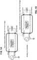
- FIGS 1A and 1B are circuit diagrams of a prior art circuit breaker that incorporates an electronics board that includes light emitting diodes (LEDs) to enable users to easily identify the trip condition and type of fault, for example an arc fault or ground fault.
- the circuit for the electronics board is powered from the load side, but power to the electronics board is interrupted when the breaker contacts are opened.
- FIGS 2A and 2B are circuit diagrams of a prior art circuit breaker, showing a miniature circuit breaker that incorporates an electronics board that includes light emitting diodes (LEDs) powered from the line power side to ensure that the LEDs remain lit when the circuit breaker is tripped.
- LEDs light emitting diodes
- an electrical shock hazard may occur if the neutral terminal of the circuit breaker is inadvertently disconnected, causing power from the line power side to flow through the circuit for the electronics board and be present on the load neutral terminal of the circuit breaker.
- FIGS 3A and 3B are circuit diagrams of a circuit breaker 100 in accordance with the invention, showing a miniature circuit breaker that incorporates an electronics board or printed circuit board assembly (PCBA) 140 powered from the line power side 106.
- the PCBA 140 may provide power to LEDS or power other functions, such as denial of service solenoids or internal communications hardware, such as radio transmitters and receivers. Power is provided from the line power side to the PCBA, while preventing an electrical shock hazard if the neutral terminal 108 of the circuit breaker is inadvertently disconnected.
- the circuit breaker includes separate contact pairs 112/122 for the line power terminal 106 to load power terminal 152 circuit path and contact pairs 110/120 for the neutral terminal 108 to load neutral terminal 150 circuit path, and both contact pairs are simultaneously opened and closed in unison.
- both line power circuit path 106/152 and neutral circuit path 108/150 are interrupted from connection to the load power 152 and load neutral 150 terminals, to prevent power from the line power side 106 to flow through the circuit board 140 and be present on the load neutral terminal 150 of the circuit breaker.
- FIG 4A is a front perspective view from the top left side of the circuit breaker of Figures 3A and 3B , with the contact pairs 110/120 and 112/122 CLOSED or in the ON position, in accordance with the invention.
- the circuit breaker 100 includes a housing 101 of the circuit breaker, including an operating handle 102 and an overcurrent tripping mechanism 130.
- the circuit breaker 100 includes a first stationary contact 112 in the housing, connected to a line power terminal 106 of the circuit breaker.
- the circuit breaker 100 includes a second stationary contact 110 in the housing, connected to a neutral terminal 108 of the circuit breaker.
- the circuit breaker 100 includes a first moveable contact 122 in the housing, coupled to a load power terminal 152 of the circuit breaker, the first moveable contact 122 mounted on a moveable actuator 104 and juxtaposed with the first stationary contact 112 to form a power circuit between the line power terminal 106 and the load power terminal 152 when the first moveable 122 and first stationary contacts 112 are closed.
- the circuit breaker 100 includes a second moveable contact 120 in the housing, connected to a load neutral terminal 150 of the circuit breaker, the second moveable contact 120 mounted on the moveable actuator 104 juxtaposed with the second stationary contact 110 to form a neutral circuit between the neutral terminal 108 and the load neutral terminal 150 when the second moveable 120 and second stationary 110 contacts are closed.
- the movable actuator 104 is configured to move the first 122 and second 120 moveable contacts in unison to open the power circuit between the respective first stationary 112 and first moveable contacts 122 and simultaneously to open the neutral circuit between the second stationary 110 and second moveable 120 contacts, in response to an actuation of the operating handle 102 or to the overcurrent tripping mechanism 130 sensing a tripping event, as shown in Figure 4B .
- the overcurrent tripping mechanism 130 includes a firing or trip solenoid 111 that releases a trip latch 109 that moves a trip lever 107 that toggles the moveable actuator 104 to open both pairs of contacts 110/120 and 112/122 when an overcurrent condition is detected.
- the movable actuator 104 toggles between the CLOSED position in Figure 4A and the OPEN position in Figure 4B with the toggle spring 105.
- the movable actuator 104 also provides an electrical isolation barrier between the first and second moveable contacts 120 and 122.
- the circuit breaker 100 includes a load-powered circuit board 142 that writes the fault type of the tripping event, via the opto-coupler 160, to the line-powered circuit board 140, at the same time as the firing or trip solenoid 111 releases the trip latch 109 that moves the trip lever 107 to open both pairs of contacts 110/120 and 112/122.
- the LEDs in the line-powered circuit board 140 then display the type of fault.
- the circuit board 140 may also host communication hardware, such as radio transmitters and receivers to communicate the tripped state of the contacts.
- the circuit board 140 may also host denial of service hardware, such as circuits and solenoids to move the moveable actuator 104, to turn the circuit breaker on and off, for example in response to commands received by the radio receiver.
- the circuit breaker 100 includes a reduced size arc chamber 115 (shown in Figure 4C ) in the housing 101 surrounding the first and second stationary contacts 110/112 and the first and second moveable contacts 120/122, corresponding to a reduced size air gap between the first moveable contact and first stationary contact and a reduced size air gap between the second moveable contact and the second stationary contact.
- the reduced size air gaps are based on dividing in half, an arc current flowing between the first and second stationary contacts and the first and second moveable contacts.
- Figure 4B is a front perspective view from the top left side of the circuit breaker of Figures 3A and 3B , with the contact pairs 110/120 and 112/122 OPEN or in the OFF position, in accordance with the invention.
- the operating handle 102 is shown in an OFF position and the contact pairs opened.
- the movable actuator 104 is configured to move the first 122 and second 120 moveable contacts in unison to open the power circuit between the respective first stationary 112 and first moveable contacts 122 and simultaneously to open the neutral circuit between the second stationary 110 and second moveable 120 contacts, in response to an actuation of the operating handle 102 or to the overcurrent tripping mechanism 130 sensing a tripping event.
- Figure 4C is a front view of the circuit breaker of Figures 3A and 3B and Figure 4B , with the contact pairs OPEN or in the OFF position, in accordance with the invention.
- the view in Figure 4C provides a clearer indication of the reduced size arc chamber 115 in the housing and a reduced size air gap between the moveable contact 120 and the stationary contact 110.
- the reduced size air gaps are based on dividing in half, an arc current flowing between the stationary contacts 110/112 and the moveable contacts 120/122.
Landscapes
- Breakers (AREA)
Applications Claiming Priority (1)
| Application Number | Priority Date | Filing Date | Title |
|---|---|---|---|
| US16/227,025 US10984974B2 (en) | 2018-12-20 | 2018-12-20 | Line side power, double break, switch neutral electronic circuit breaker |
Publications (2)
| Publication Number | Publication Date |
|---|---|
| EP3671799A1 true EP3671799A1 (de) | 2020-06-24 |
| EP3671799B1 EP3671799B1 (de) | 2023-04-19 |
Family
ID=68808053
Family Applications (1)
| Application Number | Title | Priority Date | Filing Date |
|---|---|---|---|
| EP19213943.4A Active EP3671799B1 (de) | 2018-12-20 | 2019-12-05 | Nullleiterschutzschalter mit doppelunterbrechung und netzseitiggespeister elektronischer platine |
Country Status (3)
| Country | Link |
|---|---|
| US (1) | US10984974B2 (de) |
| EP (1) | EP3671799B1 (de) |
| CN (1) | CN111354609A (de) |
Families Citing this family (1)
| Publication number | Priority date | Publication date | Assignee | Title |
|---|---|---|---|---|
| ES2946269T3 (es) * | 2018-04-23 | 2023-07-14 | Abb Spa | Disyuntor |
Citations (5)
| Publication number | Priority date | Publication date | Assignee | Title |
|---|---|---|---|---|
| EP0196241A1 (de) * | 1985-02-27 | 1986-10-01 | Merlin Gerin | Einpol- und Nulleiter-Differentialschutzschalter |
| US5245302A (en) | 1992-05-05 | 1993-09-14 | Square D Company | Automatic miniature circuit breaker with Z-axis assemblable trip mechanism |
| US20020046940A1 (en) * | 2000-10-19 | 2002-04-25 | Didier Bruckert | Rapid closure mechanism for electrical contacts |
| EP1724803A2 (de) * | 2005-05-17 | 2006-11-22 | Bticino S.P.A. | Zu einer elektrischen Schaltvorrichtung zuordenbare elektronische Einrichtung |
| EP3171385A1 (de) * | 2014-07-17 | 2017-05-24 | Chint Group Corporation | Betriebsvorrichtung eines mehrpoligen miniaturschutzschalters |
Family Cites Families (183)
| Publication number | Priority date | Publication date | Assignee | Title |
|---|---|---|---|---|
| US2618716A (en) * | 1948-06-10 | 1952-11-18 | Wadsworth Electric Mfg Co | Electric circuit breaker |
| US3421123A (en) * | 1967-06-19 | 1969-01-07 | Gen Electric | Electric circuit breaker with magnetic tripping means |
| US3464040A (en) * | 1967-09-21 | 1969-08-26 | Gen Electric | Compact circuit breaker construction |
| US3525959A (en) * | 1968-12-05 | 1970-08-25 | Westinghouse Electric Corp | Circuit breaker with improved latch reset |
| US3745414A (en) * | 1972-01-21 | 1973-07-10 | Westinghouse Electric Corp | Ground fault circuit interrupter |
| US3760308A (en) * | 1972-07-31 | 1973-09-18 | Westinghouse Electric Corp | Circuit breaker system |
| US3950714A (en) * | 1974-09-18 | 1976-04-13 | Westinghouse Electric Corporation | Self-adjusting circuit breaker with rotating trip assembly |
| US4081852A (en) * | 1974-10-03 | 1978-03-28 | Westinghouse Electric Corporation | Ground fault circuit breaker |
| GB1492906A (en) * | 1976-01-12 | 1977-11-23 | Ottermill Ltd | Electric circuit breaker |
| FR2360171A1 (fr) * | 1976-07-30 | 1978-02-24 | Unelec | Mecanisme de commande de disjoncteur |
| US4164719A (en) * | 1978-04-03 | 1979-08-14 | Gould Inc. | Load management apparatus for residential load centers |
| US4232282A (en) * | 1978-12-18 | 1980-11-04 | Gould Inc. | Circuit breaker having means to facilitate assembly thereof |
| US4263492A (en) * | 1979-09-21 | 1981-04-21 | Westinghouse Electric Corp. | Circuit breaker with anti-bounce mechanism |
| DE8023509U1 (de) * | 1980-08-29 | 1980-11-27 | Siemens Ag, 1000 Berlin Und 8000 Muenchen | Niederspannungs-Schutzschalter für Sperrhebel |
| IT8223118V0 (it) * | 1982-10-07 | 1982-10-07 | Sace Spa | Interruttore elettrico con arresto della corsa della leva di comando in caso di saldatura dei contatti. |
| US4472696A (en) * | 1982-12-27 | 1984-09-18 | Gte Laboratories Incorporated | Circuit breaker |
| US4513268A (en) * | 1983-12-14 | 1985-04-23 | General Electric Company | Automated Q-line circuit breaker |
| US4616200A (en) * | 1984-09-12 | 1986-10-07 | Square D Company | Circuit breaker |
| US4594491A (en) * | 1984-09-28 | 1986-06-10 | Westinghouse Electric Corp. | Molded case circuit breaker with a trip mechanism having an intermediate latch lever |
| US4630019A (en) * | 1984-09-28 | 1986-12-16 | Westinghouse Electric Corp. | Molded case circuit breaker with calibration adjusting means for a bimetal |
| US4604596A (en) * | 1985-02-01 | 1986-08-05 | Matsushita Electric Works, Ltd. | Remotely controllable circuit breaker |
| US4686600A (en) * | 1985-04-22 | 1987-08-11 | General Electric Company | Modular ground fault circuit breaker |
| US4609898A (en) * | 1985-07-05 | 1986-09-02 | General Electric Company | Molded case circuit breaker having a thermoplastic cover |
| US4623859A (en) * | 1985-08-13 | 1986-11-18 | Square D Company | Remote control circuit breaker |
| US4713639A (en) * | 1987-02-20 | 1987-12-15 | Westinghouse Electric Corp. | Circuit breaker with push-to-trip button and trip bar |
| US4969063A (en) | 1989-05-16 | 1990-11-06 | Square D Company | Circuit breaker with status indicating lights |
| EP0443684B1 (de) * | 1990-02-23 | 1995-10-18 | Matsushita Electric Works, Ltd. | Schutzschalter |
| US5331301A (en) * | 1990-02-23 | 1994-07-19 | Square D Company | Circuit breaker |
| US5165532A (en) * | 1991-05-29 | 1992-11-24 | Westinghouse Electric Corp. | Circuit breaker with interlock for welding contacts |
| US5213206A (en) * | 1991-05-29 | 1993-05-25 | Westinghouse Electric Corp. | Circuit breaker with positive on/off interlock |
| US5301083A (en) * | 1991-09-30 | 1994-04-05 | Eaton Corporation | Remote control residential circuit breaker |
| US5373411A (en) * | 1991-09-30 | 1994-12-13 | Eaton Corporation | Remote control circuit breaker system |
| US5196815A (en) * | 1992-01-31 | 1993-03-23 | Westinghouse Electric Corp. | Miniature circuit breaker |
| US5250918A (en) * | 1992-05-05 | 1993-10-05 | Square D Company | Automatic miniature circuit breaker with Z-axis assemblage current response mechanism |
| US5302787A (en) * | 1992-05-05 | 1994-04-12 | Square D Company | Automatic miniature circuit breaker with Z-axis assemblable contact assembly |
| US5245305A (en) * | 1992-09-24 | 1993-09-14 | General Electric Company | Circuit breaker enclosure material identification |
| US5296664A (en) * | 1992-11-16 | 1994-03-22 | Westinghouse Electric Corp. | Circuit breaker with positive off protection |
| FR2704354B1 (fr) * | 1993-04-20 | 1995-06-23 | Merlin Gerin | Mecanisme de commande d'un disjoncteur electrique modulaire. |
| US5510759A (en) * | 1994-06-23 | 1996-04-23 | Eaton Corporation | Miniature circuit breaker with ground fault electronics supported by stiff conductors for easy assembly |
| US5483211A (en) * | 1994-06-23 | 1996-01-09 | Eaton Corporation | Two-pole compartmentalized ground fault miniature circuit breaker with a single central electronics compartment |
| US5546060A (en) * | 1994-12-22 | 1996-08-13 | Eaton Corporation | Support plate for a circuit breaker |
| US5608198A (en) * | 1995-06-26 | 1997-03-04 | Square D Company | Circuit breaker arrangement for protection against electrical arcs |
| US5581063A (en) * | 1995-06-26 | 1996-12-03 | Square D Company | Arc-resistant shield for protecting a movable contact carrier of a circuit breaker |
| US5834997A (en) * | 1996-08-23 | 1998-11-10 | Square D Company | Coupling member for securing a spring to a rotatable motor shaft |
| US5831500A (en) * | 1996-08-23 | 1998-11-03 | Square D Company | Trip flag guide for a circuit breaker |
| US5861784A (en) * | 1996-08-23 | 1999-01-19 | Square D Company | Manual override mechanism for a remote controlled circuit breaker |
| US5821839A (en) * | 1996-08-23 | 1998-10-13 | Square D Company | Improved calibration means for a circuit breaker |
| US5818671A (en) * | 1996-10-04 | 1998-10-06 | General Electric Company | Circuit breaker with arcing fault detection module |
| US5706154A (en) * | 1996-10-04 | 1998-01-06 | General Electric Company | Residential circuit breaker with arcing fault detection |
| US5844188A (en) * | 1996-12-19 | 1998-12-01 | Siemens Energy & Automation, Inc. | Circuit breaker with improved trip mechanism |
| US5894260A (en) * | 1996-12-19 | 1999-04-13 | Siemens Energy & Automation, Inc. | Thermal sensing bi-metal trip actuator for a circuit breaker |
| US5866996A (en) * | 1996-12-19 | 1999-02-02 | Siemens Energy & Automation, Inc. | Contact arm with internal in-line spring |
| US6087914A (en) * | 1996-12-19 | 2000-07-11 | Siemens Energy & Automation, Inc. | Circuit breaker combination thermal and magnetic trip actuator |
| US5859578A (en) * | 1997-03-04 | 1999-01-12 | General Electric Company | Current limiting shunt for current limiting circuit breakers |
| US5805038A (en) * | 1997-04-29 | 1998-09-08 | Eaton Corporation | Shock absorber for circuit breaker |
| US5831498A (en) * | 1997-04-30 | 1998-11-03 | Eaton Corporation | Molded case circuit breaker with adapter for use with ring lug terminations |
| IT1292453B1 (it) * | 1997-07-02 | 1999-02-08 | Aeg Niederspannungstech Gmbh | Gruppo rotante di contatti per interrutttori di alta portata |
| US5847630A (en) * | 1997-08-01 | 1998-12-08 | General Electric Company | Compact circuit breaker incorporating a polymer current limiter |
| US5831509A (en) * | 1997-10-22 | 1998-11-03 | Eaton Corporation | Circuit breaker with sense bar to sense current from voltage drop across bimetal |
| US5872495A (en) * | 1997-12-10 | 1999-02-16 | Siemens Energy & Automation, Inc. | Variable thermal and magnetic structure for a circuitbreaker trip unit |
| US5933306A (en) * | 1998-01-14 | 1999-08-03 | General Electric Company | Circuit breaker with ground fault detection module |
| US5886600A (en) * | 1998-01-14 | 1999-03-23 | General Electric Company | Modular thermal magnetic trip unit for rapid circuit interruption |
| US6104265A (en) * | 1998-02-19 | 2000-08-15 | Eaton Corporation | Miniature circuit breaker with multipurpose auxiliary member |
| US6072136A (en) * | 1998-05-07 | 2000-06-06 | Eaton Corporation | Electrical switching apparatus with modular operating mechanism for mounting and controlling large compression close spring |
| US6114641A (en) * | 1998-05-29 | 2000-09-05 | General Electric Company | Rotary contact assembly for high ampere-rated circuit breakers |
| US6087913A (en) * | 1998-11-20 | 2000-07-11 | General Electric Company | Circuit breaker mechanism for a rotary contact system |
| US6037555A (en) * | 1999-01-05 | 2000-03-14 | General Electric Company | Rotary contact circuit breaker venting arrangement including current transformer |
| US6166344A (en) * | 1999-03-23 | 2000-12-26 | General Electric Company | Circuit breaker handle block |
| US6259340B1 (en) * | 1999-05-10 | 2001-07-10 | General Electric Company | Circuit breaker with a dual test button mechanism |
| US6188036B1 (en) * | 1999-08-03 | 2001-02-13 | General Electric Company | Bottom vented circuit breaker capable of top down assembly onto equipment |
| US6396369B1 (en) * | 1999-08-27 | 2002-05-28 | General Electric Company | Rotary contact assembly for high ampere-rated circuit breakers |
| US6232570B1 (en) * | 1999-09-16 | 2001-05-15 | General Electric Company | Arcing contact arrangement |
| US6317018B1 (en) * | 1999-10-26 | 2001-11-13 | General Electric Company | Circuit breaker mechanism |
| US6232856B1 (en) * | 1999-11-02 | 2001-05-15 | General Electric Company | Magnetic shunt assembly |
| US6310307B1 (en) * | 1999-12-17 | 2001-10-30 | General Electric Company | Circuit breaker rotary contact arm arrangement |
| US6184761B1 (en) * | 1999-12-20 | 2001-02-06 | General Electric Company | Circuit breaker rotary contact arrangement |
| US6239677B1 (en) * | 2000-02-10 | 2001-05-29 | General Electric Company | Circuit breaker thermal magnetic trip unit |
| US6429759B1 (en) * | 2000-02-14 | 2002-08-06 | General Electric Company | Split and angled contacts |
| US6307453B1 (en) * | 2000-02-15 | 2001-10-23 | Eaton Corporation | Circuit breaker with instantaneous trip provided by main conductor routed through magnetic circuit of electronic trip motor |
| US6225883B1 (en) * | 2000-02-15 | 2001-05-01 | Eaton Corporation | Circuit breaker with latch and toggle mechanism operating in perpendicular planes |
| US6222143B1 (en) * | 2000-02-18 | 2001-04-24 | Siemens Energy & Automation, Inc. | Positive off toggle mechanism |
| US6281458B1 (en) * | 2000-02-24 | 2001-08-28 | General Electric Company | Circuit breaker auxiliary magnetic trip unit with pressure sensitive release |
| US6388858B1 (en) * | 2000-02-28 | 2002-05-14 | Eaton Corporation | Remotely controllable circuit breaker |
| US6259339B1 (en) * | 2000-02-28 | 2001-07-10 | Eaton Coporation | Remotely controllable circuit breaker with combined visual indication of state and manual override |
| US6204743B1 (en) * | 2000-02-29 | 2001-03-20 | General Electric Company | Dual connector strap for a rotary contact circuit breaker |
| US6340925B1 (en) * | 2000-03-01 | 2002-01-22 | General Electric Company | Circuit breaker mechanism tripping cam |
| US6346868B1 (en) * | 2000-03-01 | 2002-02-12 | General Electric Company | Circuit interrupter operating mechanism |
| US6448521B1 (en) * | 2000-03-01 | 2002-09-10 | General Electric Company | Blocking apparatus for circuit breaker contact structure |
| US6366438B1 (en) * | 2000-03-06 | 2002-04-02 | General Electric Company | Circuit interrupter rotary contact arm |
| US6459059B1 (en) * | 2000-03-16 | 2002-10-01 | General Electric Company | Return spring for a circuit interrupter operating mechanism |
| US6479774B1 (en) * | 2000-03-17 | 2002-11-12 | General Electric Company | High energy closing mechanism for circuit breakers |
| US6232860B1 (en) * | 2000-06-23 | 2001-05-15 | General Electric Company | Armature for latching a circuit breaker trip unit |
| US6477022B1 (en) * | 2000-07-12 | 2002-11-05 | Eaton Corporation | Ground fault of arc fault circuit breaker employing first and second separable contacts and plural actuating mechanisms |
| US6239676B1 (en) * | 2000-08-28 | 2001-05-29 | Eaton Corporation | Two pole circuit breaker calibrated in assembled state |
| US6483408B1 (en) * | 2000-10-12 | 2002-11-19 | Eaton Corporation | Circuit breaker with bypass for redirecting high transient current and associated method |
| US6400245B1 (en) * | 2000-10-13 | 2002-06-04 | General Electric Company | Draw out interlock for circuit breakers |
| US6531941B1 (en) * | 2000-10-19 | 2003-03-11 | General Electric Company | Clip for a conductor in a rotary breaker |
| US6429760B1 (en) * | 2000-10-19 | 2002-08-06 | General Electric Company | Cross bar for a conductor in a rotary breaker |
| US6362711B1 (en) * | 2000-11-10 | 2002-03-26 | General Electric Company | Circuit breaker cover with screw locating feature |
| US6380829B1 (en) * | 2000-11-21 | 2002-04-30 | General Electric Company | Motor operator interlock and method for circuit breakers |
| US6486759B2 (en) * | 2000-11-29 | 2002-11-26 | General Electric Company | Circuit breaker calibration screw |
| US6515569B2 (en) * | 2000-12-18 | 2003-02-04 | Eaton Corporation | Circuit breaker with bypass conductor commutating current out of the bimetal during short circuit interruption and method of commutating current out of bimetal |
| US6448522B1 (en) * | 2001-01-30 | 2002-09-10 | General Electric Company | Compact high speed motor operator for a circuit breaker |
| US6724284B2 (en) * | 2001-02-02 | 2004-04-20 | Eaton Corporation | Circuit breaker |
| US6476337B2 (en) * | 2001-02-26 | 2002-11-05 | General Electric Company | Auxiliary switch actuation arrangement |
| KR100417579B1 (ko) * | 2001-04-13 | 2004-02-05 | 엘지산전 주식회사 | 회로차단기의 중성극 개폐장치 |
| US6522228B2 (en) * | 2001-04-30 | 2003-02-18 | Eaton Corporation | Circuit breaker including an arc fault trip actuator having an indicator latch and a trip latch |
| US6542056B2 (en) * | 2001-04-30 | 2003-04-01 | Eaton Corporation | Circuit breaker having a movable and illuminable arc fault indicator |
| US6469600B1 (en) * | 2001-07-27 | 2002-10-22 | Eaton Corporation | Remote control circuit breaker with a by-pass lead |
| US6507256B1 (en) * | 2001-08-17 | 2003-01-14 | General Electric Company | Auxiliary magnetic trip system |
| US6650515B2 (en) * | 2001-08-27 | 2003-11-18 | Eaton Corporation | Circuit breaker including power supply monitor circuit to disable a trip mechanism |
| US6861930B2 (en) * | 2001-11-15 | 2005-03-01 | Eaton Corporation | Transfer switch including a circuit breaker housing |
| US6768402B2 (en) * | 2002-04-15 | 2004-07-27 | Eaton Corporation | Externally controllable circuit breaker |
| US6897747B2 (en) * | 2002-05-10 | 2005-05-24 | Joseph T. Brandon | Circuit breaker |
| US6489867B1 (en) * | 2002-05-22 | 2002-12-03 | Eaton Corporation | Separating pins for the shunt wires of a circuit breaker |
| US6801110B2 (en) * | 2002-06-03 | 2004-10-05 | Eaton Corporation | Spacer for the shunt wires within a circuit breaker |
| US6614334B1 (en) * | 2002-06-27 | 2003-09-02 | Eaton Corporation | Circuit breaker including two circuit breaker mechanisms and an operating handle |
| US6667680B1 (en) * | 2002-06-27 | 2003-12-23 | Eaton Corporation | Circuit breaker |
| US6917267B2 (en) * | 2003-02-05 | 2005-07-12 | Eaton Corporation | Non-conductive barrier for separating a circuit breaker trip spring and cradle |
| US6850134B2 (en) * | 2003-02-05 | 2005-02-01 | Eaton Corporation | Circuit breaker operating mechanism with a metal cradle pivot |
| US6879228B2 (en) * | 2003-02-05 | 2005-04-12 | Eaton Corporation | Circuit breaker including magnetic trip mechanism |
| US6838961B2 (en) * | 2003-02-05 | 2005-01-04 | Eaton Corporation | Self-contained mechanism on a frame |
| US6759931B1 (en) * | 2003-02-05 | 2004-07-06 | Eaton Corporation | Magnetic member, circuit breaker employing the same, and method of manufacturing the same |
| US6714108B1 (en) * | 2003-04-02 | 2004-03-30 | Eaton Corporation | Circuit breaker including mechanism for breaking tack weld |
| US6812815B2 (en) * | 2003-04-02 | 2004-11-02 | Eaton Corporation | Remotely controllable circuit breaker including bypass magnet circuit |
| US6894594B2 (en) * | 2003-06-20 | 2005-05-17 | Eaton Corporation | Circuit breaker including a cradle and a pivot pin therefor |
| US6903289B2 (en) * | 2003-08-28 | 2005-06-07 | Eaton Corporation | Circuit breaker employing an illuminated operating handle |
| US6864447B1 (en) * | 2003-08-28 | 2005-03-08 | Eaton Corporation | Circuit breaker empolying illuminating indicators for open and closed positions |
| US6870115B1 (en) * | 2003-10-24 | 2005-03-22 | Eaton Corporation | Circuit breaker including extension spring(s) between operating mechanism pivot and operating handle |
| US6803536B1 (en) * | 2003-10-24 | 2004-10-12 | Eaton Corporation | Circuit breaker including independent link to operating handle |
| US6800824B1 (en) * | 2003-10-24 | 2004-10-05 | Eaton Corporation | Circuit breaker including frame having stop for operating mechanism link |
| US6800823B1 (en) * | 2003-10-24 | 2004-10-05 | Eaton Corporation | Circuit breaker including lever for snap close operation |
| US6803535B1 (en) * | 2004-02-19 | 2004-10-12 | Eaton Corporation | Circuit breaker with a visual indication of a trip |
| US7342474B2 (en) * | 2004-03-29 | 2008-03-11 | General Electric Company | Circuit breaker configured to be remotely operated |
| US7061349B2 (en) * | 2004-03-29 | 2006-06-13 | General Electric Company | Circuit breaker configured to be remotely operated |
| US7019606B2 (en) * | 2004-03-29 | 2006-03-28 | General Electric Company | Circuit breaker configured to be remotely operated |
| JP4466209B2 (ja) * | 2004-06-10 | 2010-05-26 | 富士電機機器制御株式会社 | 回路遮断器 |
| DE102005038149A1 (de) * | 2005-08-12 | 2007-02-22 | Abb Patent Gmbh | Leitungsschutzschalter |
| DE102005041231B4 (de) * | 2005-08-31 | 2009-11-26 | Abb Ag | Elektrisches Schaltgerät |
| US20070085639A1 (en) * | 2005-10-19 | 2007-04-19 | Eaton Corporation | Circuit breaker intermediate latch stop |
| KR200419048Y1 (ko) * | 2006-03-17 | 2006-06-16 | 엘에스산전 주식회사 | 배선용 차단기 |
| US7518482B2 (en) * | 2006-10-10 | 2009-04-14 | Dennis William Fleege | Trip unit having a plurality of stacked bimetal elements |
| US7397333B2 (en) * | 2006-10-18 | 2008-07-08 | Square D Company | Trip unit having bimetal element located outside the yoke |
| EP2023365B1 (de) * | 2007-08-10 | 2015-09-16 | LS Industrial Systems Co., Ltd | Gekapselter Leistungsschalter mit Kontakt auf dem Mechanismus |
| US7800478B2 (en) * | 2008-05-30 | 2010-09-21 | Eaton Corporation | Electrical switching apparatus and heater assembly therefor |
| US8971055B2 (en) * | 2008-12-16 | 2015-03-03 | Schneider Electric USA, Inc. | Residential circuit breaker with flexible printed circuit boards |
| US8169757B2 (en) * | 2008-12-17 | 2012-05-01 | Schneider Electric USA, Inc. | Circuit breaker with bistable display |
| US7999641B2 (en) * | 2008-12-18 | 2011-08-16 | Broghammer William J | Circuit breaker having reduced auxiliary trip requirements |
| US8089282B2 (en) * | 2009-04-18 | 2012-01-03 | General Electric Company | Test assembly for a circuit breaker |
| GB0915379D0 (en) * | 2009-09-03 | 2009-10-07 | Deepstream Technologies Ltd | Miniature circuit breaker |
| US8058580B2 (en) * | 2009-09-16 | 2011-11-15 | Eaton Corporation | Electrical switching apparatus and linking assembly therefor |
| US8735758B2 (en) * | 2009-10-05 | 2014-05-27 | Siemens Industry, Inc. | Circuit breaker having dual arc chamber |
| US8735759B2 (en) * | 2009-11-03 | 2014-05-27 | Schneider Electric USA, Inc. | Features to limit the exhaust debris exiting a circuit breaker |
| US8258898B2 (en) * | 2009-11-16 | 2012-09-04 | Schneider Electric USA, Inc. | Low cost multi-pole circuit breakers with shared components |
| US8243411B2 (en) * | 2009-12-22 | 2012-08-14 | Schneider Electric USA, Inc. | Electronic miniature circuit breaker with trip indication using the breaker tripping function as the feedback mechanism |
| US8149075B2 (en) * | 2010-02-19 | 2012-04-03 | Siemens Industry, Inc. | Plastic cradle |
| US9048054B2 (en) * | 2010-11-30 | 2015-06-02 | Schneider Electric USA, Inc. | Circuit breaker with plug on neutral connection lock-out mechanism |
| US8471655B2 (en) * | 2011-01-05 | 2013-06-25 | Schneider Electric USA, Inc. | Piston trip reset lever |
| US8749329B2 (en) * | 2011-04-14 | 2014-06-10 | Carling Technologies, Inc. | Magnetic circuit interrupter with current limiting capability |
| US8604374B2 (en) * | 2011-06-27 | 2013-12-10 | Schneider Electric USA, Inc. | Moveable contact closing energy transfer system for miniature circuit breakers |
| US9058939B2 (en) * | 2011-06-29 | 2015-06-16 | Schneider Electric USA, Inc. | Configuration of an arc runner for a miniature circuit breaker |
| US8698024B2 (en) * | 2011-11-18 | 2014-04-15 | Schneider Electric USA, Inc. | Pressure sensitive trip mechanism with debris control |
| DE102012203294A1 (de) * | 2012-03-02 | 2013-09-05 | Siemens Aktiengesellschaft | Schaltschloss eines Leistungsschalters |
| US20140158508A1 (en) * | 2012-12-10 | 2014-06-12 | Schneider Electric USA, Inc. | Flexible conductor (braid) bonded to low material cost plug on jaw |
| US20140176293A1 (en) * | 2012-12-21 | 2014-06-26 | Schneider Electric USA, Inc. | Mechanical flexible thermal trip unit for miniature circuit breakers |
| US8872606B1 (en) * | 2013-04-23 | 2014-10-28 | Eaton Corporation | Bimetal and magnetic armature providing an arc splatter resistant offset therebetween, and circuit breaker including the same |
| AU2013396240B2 (en) * | 2013-06-27 | 2018-02-15 | Schneider Electric USA, Inc. | Plug-on neutral connection |
| US10002736B2 (en) * | 2013-12-05 | 2018-06-19 | Schneider Electric USA, Inc. | Double make double break interrupter module with independent blades |
| CA2929437C (en) * | 2013-12-27 | 2021-06-15 | Schneider Electric USA, Inc. | Two piece handle for miniature circuit breakers |
| DE102014107265B4 (de) * | 2014-05-22 | 2020-01-02 | Eaton Intelligent Power Limited | Schaltgerät |
| US9607797B2 (en) * | 2014-07-01 | 2017-03-28 | Schneider Electric USA, Inc. | Low movement trip and integrated signal flag for miniature circuit breakers |
| US9564280B2 (en) * | 2014-08-01 | 2017-02-07 | Schneider Electric USA, Inc. | Panel board to circuit breaker positive retention interlock |
| US9412548B2 (en) * | 2014-08-13 | 2016-08-09 | Eaton Corporation | Circuit breakers with handle bearing sleeves |
| US9620303B2 (en) * | 2014-08-13 | 2017-04-11 | Eaton Corporation | Circuit breakers with handle bearing pins |
| US9697975B2 (en) * | 2014-12-03 | 2017-07-04 | Eaton Corporation | Circuit breakers with moving contact arm with spaced apart contacts |
| US9613774B2 (en) * | 2014-12-18 | 2017-04-04 | Eaton Corporation | Circuit breakers with common trip cams and related trip cams |
| US9863798B2 (en) * | 2015-02-27 | 2018-01-09 | Schneider Electric Systems Usa, Inc. | Systems and methods for multiphase flow metering accounting for dissolved gas |
| CN105158684A (zh) * | 2015-06-04 | 2015-12-16 | 常熟开关制造有限公司(原常熟开关厂) | 智能断路器故障显示方法、智能断路器、故障识别终端 |
| US9502200B1 (en) * | 2015-12-08 | 2016-11-22 | Schneider Electric USA, Inc. | Low tolerance magnetic trip for a miniature circuit |
| US10249464B2 (en) * | 2016-05-20 | 2019-04-02 | Eaton Intelligent Power Limited | Modular circuit breaker and method of assembling |
| EP3373319B1 (de) * | 2017-03-09 | 2021-11-10 | LSIS Co., Ltd. | Schutzschalter mit sofortauslösemechanismus |
| US10622800B2 (en) * | 2017-08-09 | 2020-04-14 | Schneider Electric USA, Inc. | Integrated arc fault and ground fault current sensing package |
| US10326264B1 (en) * | 2018-04-25 | 2019-06-18 | Schneider Electric USA, Inc. | Auto-monitoring redundancy for enhanced miniature circuit breaker reliability |
-
2018
- 2018-12-20 US US16/227,025 patent/US10984974B2/en active Active
-
2019
- 2019-12-05 EP EP19213943.4A patent/EP3671799B1/de active Active
- 2019-12-17 CN CN201911299128.1A patent/CN111354609A/zh active Pending
Patent Citations (5)
| Publication number | Priority date | Publication date | Assignee | Title |
|---|---|---|---|---|
| EP0196241A1 (de) * | 1985-02-27 | 1986-10-01 | Merlin Gerin | Einpol- und Nulleiter-Differentialschutzschalter |
| US5245302A (en) | 1992-05-05 | 1993-09-14 | Square D Company | Automatic miniature circuit breaker with Z-axis assemblable trip mechanism |
| US20020046940A1 (en) * | 2000-10-19 | 2002-04-25 | Didier Bruckert | Rapid closure mechanism for electrical contacts |
| EP1724803A2 (de) * | 2005-05-17 | 2006-11-22 | Bticino S.P.A. | Zu einer elektrischen Schaltvorrichtung zuordenbare elektronische Einrichtung |
| EP3171385A1 (de) * | 2014-07-17 | 2017-05-24 | Chint Group Corporation | Betriebsvorrichtung eines mehrpoligen miniaturschutzschalters |
Also Published As
| Publication number | Publication date |
|---|---|
| EP3671799B1 (de) | 2023-04-19 |
| CN111354609A (zh) | 2020-06-30 |
| US20200203108A1 (en) | 2020-06-25 |
| US10984974B2 (en) | 2021-04-20 |
Similar Documents
| Publication | Publication Date | Title |
|---|---|---|
| US11322916B2 (en) | Solid-state circuit breaker with galvanic isolation | |
| CA2040863C (en) | Instantaneous trip device of a circuit breaker | |
| US6671145B2 (en) | Reset lockout mechanism and independent trip mechanism for center latch circuit interrupting device | |
| CA1252192A (en) | Shunt effect low-voltage circuit-breaker | |
| EP1814133B1 (de) | Schaltvorrichtung | |
| US7554781B1 (en) | Protective device with an auxiliary switch | |
| US20060018062A1 (en) | Ground fault circuit interrupter with reverse wiring protection | |
| AU2009214807A1 (en) | A Residual-Current Circuit Breaker | |
| AU2019210620B2 (en) | Circuit Breaker With Slide To Test Function | |
| MX9604381A (es) | Dispositivo de control y señalizacion para conmutador de proteccion. | |
| EP2506283B1 (de) | Kompakter Reststromschalter mit Überstromschutz | |
| EP2136383B1 (de) | Steuervorrichtung für eine automatische Rückstellungsvorrichtung | |
| EP3671799B1 (de) | Nullleiterschutzschalter mit doppelunterbrechung und netzseitiggespeister elektronischer platine | |
| CN209859890U (zh) | 断路器的跳闸机构 | |
| CA2464165A1 (en) | Remotely controllable circuit breaker including bypass magnet circuit | |
| RU2742927C1 (ru) | Устройство защиты цепи и узел защиты цепи, включающий в себя устройство защиты цепи | |
| AU2003214138B2 (en) | Circuit breaker having fault-current cutoff | |
| GB2557376A (en) | A System for protecting an electrical circuit | |
| CN109994346B (zh) | 单极或多极断路器和模块化系统 | |
| AU2003214137B9 (en) | Circuit breaker having double pole interruption | |
| JP2017199674A (ja) | 枠付き指領域を有する回路遮断器 | |
| KR20180099329A (ko) | 누전차단기의 누전 표시 장치 | |
| CN118588504A (zh) | 漏电保护一体式断路器 | |
| CN116435149A (zh) | 低压保护开关设备和组装方法 | |
| CN113012996A (zh) | 复位元件和具有这种复位元件的电气开关 |
Legal Events
| Date | Code | Title | Description |
|---|---|---|---|
| PUAI | Public reference made under article 153(3) epc to a published international application that has entered the european phase |
Free format text: ORIGINAL CODE: 0009012 |
|
| STAA | Information on the status of an ep patent application or granted ep patent |
Free format text: STATUS: THE APPLICATION HAS BEEN PUBLISHED |
|
| AK | Designated contracting states |
Kind code of ref document: A1 Designated state(s): AL AT BE BG CH CY CZ DE DK EE ES FI FR GB GR HR HU IE IS IT LI LT LU LV MC MK MT NL NO PL PT RO RS SE SI SK SM TR |
|
| AX | Request for extension of the european patent |
Extension state: BA ME |
|
| STAA | Information on the status of an ep patent application or granted ep patent |
Free format text: STATUS: REQUEST FOR EXAMINATION WAS MADE |
|
| 17P | Request for examination filed |
Effective date: 20201222 |
|
| RBV | Designated contracting states (corrected) |
Designated state(s): AL AT BE BG CH CY CZ DE DK EE ES FI FR GB GR HR HU IE IS IT LI LT LU LV MC MK MT NL NO PL PT RO RS SE SI SK SM TR |
|
| STAA | Information on the status of an ep patent application or granted ep patent |
Free format text: STATUS: EXAMINATION IS IN PROGRESS |
|
| 17Q | First examination report despatched |
Effective date: 20210202 |
|
| GRAP | Despatch of communication of intention to grant a patent |
Free format text: ORIGINAL CODE: EPIDOSNIGR1 |
|
| STAA | Information on the status of an ep patent application or granted ep patent |
Free format text: STATUS: GRANT OF PATENT IS INTENDED |
|
| INTG | Intention to grant announced |
Effective date: 20220810 |
|
| GRAJ | Information related to disapproval of communication of intention to grant by the applicant or resumption of examination proceedings by the epo deleted |
Free format text: ORIGINAL CODE: EPIDOSDIGR1 |
|
| STAA | Information on the status of an ep patent application or granted ep patent |
Free format text: STATUS: EXAMINATION IS IN PROGRESS |
|
| GRAP | Despatch of communication of intention to grant a patent |
Free format text: ORIGINAL CODE: EPIDOSNIGR1 |
|
| STAA | Information on the status of an ep patent application or granted ep patent |
Free format text: STATUS: GRANT OF PATENT IS INTENDED |
|
| INTC | Intention to grant announced (deleted) | ||
| INTG | Intention to grant announced |
Effective date: 20221220 |
|
| GRAS | Grant fee paid |
Free format text: ORIGINAL CODE: EPIDOSNIGR3 |
|
| GRAA | (expected) grant |
Free format text: ORIGINAL CODE: 0009210 |
|
| STAA | Information on the status of an ep patent application or granted ep patent |
Free format text: STATUS: THE PATENT HAS BEEN GRANTED |
|
| AK | Designated contracting states |
Kind code of ref document: B1 Designated state(s): AL AT BE BG CH CY CZ DE DK EE ES FI FR GB GR HR HU IE IS IT LI LT LU LV MC MK MT NL NO PL PT RO RS SE SI SK SM TR |
|
| REG | Reference to a national code |
Ref country code: GB Ref legal event code: FG4D |
|
| REG | Reference to a national code |
Ref country code: CH Ref legal event code: EP |
|
| REG | Reference to a national code |
Ref country code: DE Ref legal event code: R096 Ref document number: 602019027692 Country of ref document: DE |
|
| REG | Reference to a national code |
Ref country code: IE Ref legal event code: FG4D |
|
| REG | Reference to a national code |
Ref country code: AT Ref legal event code: REF Ref document number: 1561817 Country of ref document: AT Kind code of ref document: T Effective date: 20230515 |
|
| REG | Reference to a national code |
Ref country code: LT Ref legal event code: MG9D |
|
| REG | Reference to a national code |
Ref country code: NL Ref legal event code: MP Effective date: 20230419 |
|
| REG | Reference to a national code |
Ref country code: AT Ref legal event code: MK05 Ref document number: 1561817 Country of ref document: AT Kind code of ref document: T Effective date: 20230419 |
|
| PG25 | Lapsed in a contracting state [announced via postgrant information from national office to epo] |
Ref country code: NL Free format text: LAPSE BECAUSE OF FAILURE TO SUBMIT A TRANSLATION OF THE DESCRIPTION OR TO PAY THE FEE WITHIN THE PRESCRIBED TIME-LIMIT Effective date: 20230419 |
|
| PG25 | Lapsed in a contracting state [announced via postgrant information from national office to epo] |
Ref country code: SE Free format text: LAPSE BECAUSE OF FAILURE TO SUBMIT A TRANSLATION OF THE DESCRIPTION OR TO PAY THE FEE WITHIN THE PRESCRIBED TIME-LIMIT Effective date: 20230419 Ref country code: PT Free format text: LAPSE BECAUSE OF FAILURE TO SUBMIT A TRANSLATION OF THE DESCRIPTION OR TO PAY THE FEE WITHIN THE PRESCRIBED TIME-LIMIT Effective date: 20230821 Ref country code: NO Free format text: LAPSE BECAUSE OF FAILURE TO SUBMIT A TRANSLATION OF THE DESCRIPTION OR TO PAY THE FEE WITHIN THE PRESCRIBED TIME-LIMIT Effective date: 20230719 Ref country code: ES Free format text: LAPSE BECAUSE OF FAILURE TO SUBMIT A TRANSLATION OF THE DESCRIPTION OR TO PAY THE FEE WITHIN THE PRESCRIBED TIME-LIMIT Effective date: 20230419 Ref country code: AT Free format text: LAPSE BECAUSE OF FAILURE TO SUBMIT A TRANSLATION OF THE DESCRIPTION OR TO PAY THE FEE WITHIN THE PRESCRIBED TIME-LIMIT Effective date: 20230419 |
|
| PG25 | Lapsed in a contracting state [announced via postgrant information from national office to epo] |
Ref country code: RS Free format text: LAPSE BECAUSE OF FAILURE TO SUBMIT A TRANSLATION OF THE DESCRIPTION OR TO PAY THE FEE WITHIN THE PRESCRIBED TIME-LIMIT Effective date: 20230419 Ref country code: PL Free format text: LAPSE BECAUSE OF FAILURE TO SUBMIT A TRANSLATION OF THE DESCRIPTION OR TO PAY THE FEE WITHIN THE PRESCRIBED TIME-LIMIT Effective date: 20230419 Ref country code: LV Free format text: LAPSE BECAUSE OF FAILURE TO SUBMIT A TRANSLATION OF THE DESCRIPTION OR TO PAY THE FEE WITHIN THE PRESCRIBED TIME-LIMIT Effective date: 20230419 Ref country code: LT Free format text: LAPSE BECAUSE OF FAILURE TO SUBMIT A TRANSLATION OF THE DESCRIPTION OR TO PAY THE FEE WITHIN THE PRESCRIBED TIME-LIMIT Effective date: 20230419 Ref country code: IS Free format text: LAPSE BECAUSE OF FAILURE TO SUBMIT A TRANSLATION OF THE DESCRIPTION OR TO PAY THE FEE WITHIN THE PRESCRIBED TIME-LIMIT Effective date: 20230819 Ref country code: HR Free format text: LAPSE BECAUSE OF FAILURE TO SUBMIT A TRANSLATION OF THE DESCRIPTION OR TO PAY THE FEE WITHIN THE PRESCRIBED TIME-LIMIT Effective date: 20230419 Ref country code: GR Free format text: LAPSE BECAUSE OF FAILURE TO SUBMIT A TRANSLATION OF THE DESCRIPTION OR TO PAY THE FEE WITHIN THE PRESCRIBED TIME-LIMIT Effective date: 20230720 Ref country code: AL Free format text: LAPSE BECAUSE OF FAILURE TO SUBMIT A TRANSLATION OF THE DESCRIPTION OR TO PAY THE FEE WITHIN THE PRESCRIBED TIME-LIMIT Effective date: 20230419 |
|
| PG25 | Lapsed in a contracting state [announced via postgrant information from national office to epo] |
Ref country code: FI Free format text: LAPSE BECAUSE OF FAILURE TO SUBMIT A TRANSLATION OF THE DESCRIPTION OR TO PAY THE FEE WITHIN THE PRESCRIBED TIME-LIMIT Effective date: 20230419 |
|
| PG25 | Lapsed in a contracting state [announced via postgrant information from national office to epo] |
Ref country code: SK Free format text: LAPSE BECAUSE OF FAILURE TO SUBMIT A TRANSLATION OF THE DESCRIPTION OR TO PAY THE FEE WITHIN THE PRESCRIBED TIME-LIMIT Effective date: 20230419 |
|
| PGFP | Annual fee paid to national office [announced via postgrant information from national office to epo] |
Ref country code: GB Payment date: 20231219 Year of fee payment: 5 |
|
| REG | Reference to a national code |
Ref country code: DE Ref legal event code: R097 Ref document number: 602019027692 Country of ref document: DE |
|
| PG25 | Lapsed in a contracting state [announced via postgrant information from national office to epo] |
Ref country code: SM Free format text: LAPSE BECAUSE OF FAILURE TO SUBMIT A TRANSLATION OF THE DESCRIPTION OR TO PAY THE FEE WITHIN THE PRESCRIBED TIME-LIMIT Effective date: 20230419 Ref country code: SK Free format text: LAPSE BECAUSE OF FAILURE TO SUBMIT A TRANSLATION OF THE DESCRIPTION OR TO PAY THE FEE WITHIN THE PRESCRIBED TIME-LIMIT Effective date: 20230419 Ref country code: RO Free format text: LAPSE BECAUSE OF FAILURE TO SUBMIT A TRANSLATION OF THE DESCRIPTION OR TO PAY THE FEE WITHIN THE PRESCRIBED TIME-LIMIT Effective date: 20230419 Ref country code: EE Free format text: LAPSE BECAUSE OF FAILURE TO SUBMIT A TRANSLATION OF THE DESCRIPTION OR TO PAY THE FEE WITHIN THE PRESCRIBED TIME-LIMIT Effective date: 20230419 Ref country code: DK Free format text: LAPSE BECAUSE OF FAILURE TO SUBMIT A TRANSLATION OF THE DESCRIPTION OR TO PAY THE FEE WITHIN THE PRESCRIBED TIME-LIMIT Effective date: 20230419 Ref country code: CZ Free format text: LAPSE BECAUSE OF FAILURE TO SUBMIT A TRANSLATION OF THE DESCRIPTION OR TO PAY THE FEE WITHIN THE PRESCRIBED TIME-LIMIT Effective date: 20230419 |
|
| PGFP | Annual fee paid to national office [announced via postgrant information from national office to epo] |
Ref country code: FR Payment date: 20231226 Year of fee payment: 5 |
|
| PLBE | No opposition filed within time limit |
Free format text: ORIGINAL CODE: 0009261 |
|
| STAA | Information on the status of an ep patent application or granted ep patent |
Free format text: STATUS: NO OPPOSITION FILED WITHIN TIME LIMIT |
|
| 26N | No opposition filed |
Effective date: 20240122 |
|
| PGFP | Annual fee paid to national office [announced via postgrant information from national office to epo] |
Ref country code: DE Payment date: 20231227 Year of fee payment: 5 |
|
| PG25 | Lapsed in a contracting state [announced via postgrant information from national office to epo] |
Ref country code: SI Free format text: LAPSE BECAUSE OF FAILURE TO SUBMIT A TRANSLATION OF THE DESCRIPTION OR TO PAY THE FEE WITHIN THE PRESCRIBED TIME-LIMIT Effective date: 20230419 |
|
| PG25 | Lapsed in a contracting state [announced via postgrant information from national office to epo] |
Ref country code: SI Free format text: LAPSE BECAUSE OF FAILURE TO SUBMIT A TRANSLATION OF THE DESCRIPTION OR TO PAY THE FEE WITHIN THE PRESCRIBED TIME-LIMIT Effective date: 20230419 Ref country code: IT Free format text: LAPSE BECAUSE OF FAILURE TO SUBMIT A TRANSLATION OF THE DESCRIPTION OR TO PAY THE FEE WITHIN THE PRESCRIBED TIME-LIMIT Effective date: 20230419 |
|
| REG | Reference to a national code |
Ref country code: CH Ref legal event code: PL |
|
| PG25 | Lapsed in a contracting state [announced via postgrant information from national office to epo] |
Ref country code: LU Free format text: LAPSE BECAUSE OF NON-PAYMENT OF DUE FEES Effective date: 20231205 |
|
| PG25 | Lapsed in a contracting state [announced via postgrant information from national office to epo] |
Ref country code: MC Free format text: LAPSE BECAUSE OF FAILURE TO SUBMIT A TRANSLATION OF THE DESCRIPTION OR TO PAY THE FEE WITHIN THE PRESCRIBED TIME-LIMIT Effective date: 20230419 |
|
| REG | Reference to a national code |
Ref country code: BE Ref legal event code: MM Effective date: 20231231 |
|
| PG25 | Lapsed in a contracting state [announced via postgrant information from national office to epo] |
Ref country code: MC Free format text: LAPSE BECAUSE OF FAILURE TO SUBMIT A TRANSLATION OF THE DESCRIPTION OR TO PAY THE FEE WITHIN THE PRESCRIBED TIME-LIMIT Effective date: 20230419 Ref country code: LU Free format text: LAPSE BECAUSE OF NON-PAYMENT OF DUE FEES Effective date: 20231205 |