EP3671744A1 - Zonen-self-servo-schreibverfahren mit synchronisierten paralleltaktgebern - Google Patents
Zonen-self-servo-schreibverfahren mit synchronisierten paralleltaktgebern Download PDFInfo
- Publication number
- EP3671744A1 EP3671744A1 EP19217455.5A EP19217455A EP3671744A1 EP 3671744 A1 EP3671744 A1 EP 3671744A1 EP 19217455 A EP19217455 A EP 19217455A EP 3671744 A1 EP3671744 A1 EP 3671744A1
- Authority
- EP
- European Patent Office
- Prior art keywords
- frequency
- clock
- servo
- zone
- controller
- Prior art date
- Legal status (The legal status is an assumption and is not a legal conclusion. Google has not performed a legal analysis and makes no representation as to the accuracy of the status listed.)
- Pending
Links
- 230000001360 synchronised effect Effects 0.000 title abstract description 14
- 238000000034 method Methods 0.000 claims description 26
- 238000005516 engineering process Methods 0.000 abstract description 4
- 230000007704 transition Effects 0.000 abstract description 2
- 230000008569 process Effects 0.000 description 17
- 230000006870 function Effects 0.000 description 13
- 230000001419 dependent effect Effects 0.000 description 8
- 230000009977 dual effect Effects 0.000 description 8
- 238000010586 diagram Methods 0.000 description 5
- 239000000284 extract Substances 0.000 description 4
- 230000003287 optical effect Effects 0.000 description 3
- 238000007792 addition Methods 0.000 description 2
- 230000001186 cumulative effect Effects 0.000 description 2
- 238000013500 data storage Methods 0.000 description 2
- 238000004519 manufacturing process Methods 0.000 description 2
- 230000004048 modification Effects 0.000 description 2
- 238000012986 modification Methods 0.000 description 2
- 230000000644 propagated effect Effects 0.000 description 2
- 230000008901 benefit Effects 0.000 description 1
- 230000005540 biological transmission Effects 0.000 description 1
- 238000004364 calculation method Methods 0.000 description 1
- 238000004891 communication Methods 0.000 description 1
- 238000010438 heat treatment Methods 0.000 description 1
- 239000000696 magnetic material Substances 0.000 description 1
- 239000013307 optical fiber Substances 0.000 description 1
- 230000004044 response Effects 0.000 description 1
- 239000004065 semiconductor Substances 0.000 description 1
Images




Classifications
-
- G—PHYSICS
- G11—INFORMATION STORAGE
- G11B—INFORMATION STORAGE BASED ON RELATIVE MOVEMENT BETWEEN RECORD CARRIER AND TRANSDUCER
- G11B20/00—Signal processing not specific to the method of recording or reproducing; Circuits therefor
- G11B20/10—Digital recording or reproducing
- G11B20/10009—Improvement or modification of read or write signals
- G11B20/10222—Improvement or modification of read or write signals clock-related aspects, e.g. phase or frequency adjustment or bit synchronisation
- G11B20/1024—Improvement or modification of read or write signals clock-related aspects, e.g. phase or frequency adjustment or bit synchronisation wherein a phase-locked loop [PLL] is used
-
- G—PHYSICS
- G11—INFORMATION STORAGE
- G11B—INFORMATION STORAGE BASED ON RELATIVE MOVEMENT BETWEEN RECORD CARRIER AND TRANSDUCER
- G11B5/00—Recording by magnetisation or demagnetisation of a record carrier; Reproducing by magnetic means; Record carriers therefor
- G11B5/48—Disposition or mounting of heads or head supports relative to record carriers ; arrangements of heads, e.g. for scanning the record carrier to increase the relative speed
- G11B5/58—Disposition or mounting of heads or head supports relative to record carriers ; arrangements of heads, e.g. for scanning the record carrier to increase the relative speed with provision for moving the head for the purpose of maintaining alignment of the head relative to the record carrier during transducing operation, e.g. to compensate for surface irregularities of the latter or for track following
- G11B5/596—Disposition or mounting of heads or head supports relative to record carriers ; arrangements of heads, e.g. for scanning the record carrier to increase the relative speed with provision for moving the head for the purpose of maintaining alignment of the head relative to the record carrier during transducing operation, e.g. to compensate for surface irregularities of the latter or for track following for track following on disks
- G11B5/59605—Circuits
- G11B5/59616—Synchronisation; Clocking
-
- G—PHYSICS
- G11—INFORMATION STORAGE
- G11B—INFORMATION STORAGE BASED ON RELATIVE MOVEMENT BETWEEN RECORD CARRIER AND TRANSDUCER
- G11B20/00—Signal processing not specific to the method of recording or reproducing; Circuits therefor
- G11B20/10—Digital recording or reproducing
- G11B20/10009—Improvement or modification of read or write signals
- G11B20/10037—A/D conversion, D/A conversion, sampling, slicing and digital quantisation or adjusting parameters thereof
-
- G—PHYSICS
- G11—INFORMATION STORAGE
- G11B—INFORMATION STORAGE BASED ON RELATIVE MOVEMENT BETWEEN RECORD CARRIER AND TRANSDUCER
- G11B20/00—Signal processing not specific to the method of recording or reproducing; Circuits therefor
- G11B20/10—Digital recording or reproducing
- G11B20/10009—Improvement or modification of read or write signals
- G11B20/10046—Improvement or modification of read or write signals filtering or equalising, e.g. setting the tap weights of an FIR filter
-
- G—PHYSICS
- G11—INFORMATION STORAGE
- G11B—INFORMATION STORAGE BASED ON RELATIVE MOVEMENT BETWEEN RECORD CARRIER AND TRANSDUCER
- G11B20/00—Signal processing not specific to the method of recording or reproducing; Circuits therefor
- G11B20/10—Digital recording or reproducing
- G11B20/10009—Improvement or modification of read or write signals
- G11B20/10305—Improvement or modification of read or write signals signal quality assessment
- G11B20/10398—Improvement or modification of read or write signals signal quality assessment jitter, timing deviations or phase and frequency errors
- G11B20/10425—Improvement or modification of read or write signals signal quality assessment jitter, timing deviations or phase and frequency errors by counting out-of-lock events of a PLL
-
- G—PHYSICS
- G11—INFORMATION STORAGE
- G11B—INFORMATION STORAGE BASED ON RELATIVE MOVEMENT BETWEEN RECORD CARRIER AND TRANSDUCER
- G11B20/00—Signal processing not specific to the method of recording or reproducing; Circuits therefor
- G11B20/10—Digital recording or reproducing
- G11B20/12—Formatting, e.g. arrangement of data block or words on the record carriers
- G11B20/1217—Formatting, e.g. arrangement of data block or words on the record carriers on discs
-
- G—PHYSICS
- G11—INFORMATION STORAGE
- G11B—INFORMATION STORAGE BASED ON RELATIVE MOVEMENT BETWEEN RECORD CARRIER AND TRANSDUCER
- G11B20/00—Signal processing not specific to the method of recording or reproducing; Circuits therefor
- G11B20/10—Digital recording or reproducing
- G11B20/12—Formatting, e.g. arrangement of data block or words on the record carriers
- G11B20/1217—Formatting, e.g. arrangement of data block or words on the record carriers on discs
- G11B20/1251—Formatting, e.g. arrangement of data block or words on the record carriers on discs for continuous data, e.g. digitised analog information signals, pulse code modulated [PCM] data
-
- G—PHYSICS
- G11—INFORMATION STORAGE
- G11B—INFORMATION STORAGE BASED ON RELATIVE MOVEMENT BETWEEN RECORD CARRIER AND TRANSDUCER
- G11B20/00—Signal processing not specific to the method of recording or reproducing; Circuits therefor
- G11B20/10—Digital recording or reproducing
- G11B20/14—Digital recording or reproducing using self-clocking codes
-
- G—PHYSICS
- G11—INFORMATION STORAGE
- G11B—INFORMATION STORAGE BASED ON RELATIVE MOVEMENT BETWEEN RECORD CARRIER AND TRANSDUCER
- G11B5/00—Recording by magnetisation or demagnetisation of a record carrier; Reproducing by magnetic means; Record carriers therefor
- G11B5/48—Disposition or mounting of heads or head supports relative to record carriers ; arrangements of heads, e.g. for scanning the record carrier to increase the relative speed
- G11B5/58—Disposition or mounting of heads or head supports relative to record carriers ; arrangements of heads, e.g. for scanning the record carrier to increase the relative speed with provision for moving the head for the purpose of maintaining alignment of the head relative to the record carrier during transducing operation, e.g. to compensate for surface irregularities of the latter or for track following
- G11B5/596—Disposition or mounting of heads or head supports relative to record carriers ; arrangements of heads, e.g. for scanning the record carrier to increase the relative speed with provision for moving the head for the purpose of maintaining alignment of the head relative to the record carrier during transducing operation, e.g. to compensate for surface irregularities of the latter or for track following for track following on disks
- G11B5/59633—Servo formatting
-
- G—PHYSICS
- G11—INFORMATION STORAGE
- G11B—INFORMATION STORAGE BASED ON RELATIVE MOVEMENT BETWEEN RECORD CARRIER AND TRANSDUCER
- G11B5/00—Recording by magnetisation or demagnetisation of a record carrier; Reproducing by magnetic means; Record carriers therefor
- G11B5/48—Disposition or mounting of heads or head supports relative to record carriers ; arrangements of heads, e.g. for scanning the record carrier to increase the relative speed
- G11B5/58—Disposition or mounting of heads or head supports relative to record carriers ; arrangements of heads, e.g. for scanning the record carrier to increase the relative speed with provision for moving the head for the purpose of maintaining alignment of the head relative to the record carrier during transducing operation, e.g. to compensate for surface irregularities of the latter or for track following
- G11B5/596—Disposition or mounting of heads or head supports relative to record carriers ; arrangements of heads, e.g. for scanning the record carrier to increase the relative speed with provision for moving the head for the purpose of maintaining alignment of the head relative to the record carrier during transducing operation, e.g. to compensate for surface irregularities of the latter or for track following for track following on disks
- G11B5/59633—Servo formatting
- G11B5/59661—Spiral servo format
-
- G—PHYSICS
- G11—INFORMATION STORAGE
- G11B—INFORMATION STORAGE BASED ON RELATIVE MOVEMENT BETWEEN RECORD CARRIER AND TRANSDUCER
- G11B5/00—Recording by magnetisation or demagnetisation of a record carrier; Reproducing by magnetic means; Record carriers therefor
- G11B5/48—Disposition or mounting of heads or head supports relative to record carriers ; arrangements of heads, e.g. for scanning the record carrier to increase the relative speed
- G11B5/58—Disposition or mounting of heads or head supports relative to record carriers ; arrangements of heads, e.g. for scanning the record carrier to increase the relative speed with provision for moving the head for the purpose of maintaining alignment of the head relative to the record carrier during transducing operation, e.g. to compensate for surface irregularities of the latter or for track following
- G11B5/596—Disposition or mounting of heads or head supports relative to record carriers ; arrangements of heads, e.g. for scanning the record carrier to increase the relative speed with provision for moving the head for the purpose of maintaining alignment of the head relative to the record carrier during transducing operation, e.g. to compensate for surface irregularities of the latter or for track following for track following on disks
- G11B5/59633—Servo formatting
- G11B5/59666—Self servo writing
-
- G—PHYSICS
- G11—INFORMATION STORAGE
- G11B—INFORMATION STORAGE BASED ON RELATIVE MOVEMENT BETWEEN RECORD CARRIER AND TRANSDUCER
- G11B5/00—Recording by magnetisation or demagnetisation of a record carrier; Reproducing by magnetic means; Record carriers therefor
- G11B2005/0002—Special dispositions or recording techniques
- G11B2005/0005—Arrangements, methods or circuits
- G11B2005/0021—Thermally assisted recording using an auxiliary energy source for heating the recording layer locally to assist the magnetization reversal
-
- G—PHYSICS
- G11—INFORMATION STORAGE
- G11B—INFORMATION STORAGE BASED ON RELATIVE MOVEMENT BETWEEN RECORD CARRIER AND TRANSDUCER
- G11B20/00—Signal processing not specific to the method of recording or reproducing; Circuits therefor
- G11B20/10—Digital recording or reproducing
- G11B20/12—Formatting, e.g. arrangement of data block or words on the record carriers
- G11B2020/1264—Formatting, e.g. arrangement of data block or words on the record carriers wherein the formatting concerns a specific kind of data
- G11B2020/1265—Control data, system data or management information, i.e. data used to access or process user data
- G11B2020/1281—Servo information
-
- G—PHYSICS
- G11—INFORMATION STORAGE
- G11B—INFORMATION STORAGE BASED ON RELATIVE MOVEMENT BETWEEN RECORD CARRIER AND TRANSDUCER
- G11B20/00—Signal processing not specific to the method of recording or reproducing; Circuits therefor
- G11B20/10—Digital recording or reproducing
- G11B20/12—Formatting, e.g. arrangement of data block or words on the record carriers
- G11B2020/1264—Formatting, e.g. arrangement of data block or words on the record carriers wherein the formatting concerns a specific kind of data
- G11B2020/1265—Control data, system data or management information, i.e. data used to access or process user data
- G11B2020/1281—Servo information
- G11B2020/1284—Servo information in servo fields which split data fields
-
- G—PHYSICS
- G11—INFORMATION STORAGE
- G11B—INFORMATION STORAGE BASED ON RELATIVE MOVEMENT BETWEEN RECORD CARRIER AND TRANSDUCER
- G11B20/00—Signal processing not specific to the method of recording or reproducing; Circuits therefor
- G11B20/10—Digital recording or reproducing
- G11B20/12—Formatting, e.g. arrangement of data block or words on the record carriers
- G11B2020/1264—Formatting, e.g. arrangement of data block or words on the record carriers wherein the formatting concerns a specific kind of data
- G11B2020/1265—Control data, system data or management information, i.e. data used to access or process user data
- G11B2020/1287—Synchronisation pattern, e.g. VCO fields
-
- G—PHYSICS
- G11—INFORMATION STORAGE
- G11B—INFORMATION STORAGE BASED ON RELATIVE MOVEMENT BETWEEN RECORD CARRIER AND TRANSDUCER
- G11B20/00—Signal processing not specific to the method of recording or reproducing; Circuits therefor
- G11B20/10—Digital recording or reproducing
- G11B20/14—Digital recording or reproducing using self-clocking codes
- G11B20/1403—Digital recording or reproducing using self-clocking codes characterised by the use of two levels
- G11B2020/1484—Codewords used in servo patterns
-
- G—PHYSICS
- G11—INFORMATION STORAGE
- G11B—INFORMATION STORAGE BASED ON RELATIVE MOVEMENT BETWEEN RECORD CARRIER AND TRANSDUCER
- G11B2220/00—Record carriers by type
- G11B2220/20—Disc-shaped record carriers
- G11B2220/25—Disc-shaped record carriers characterised in that the disc is based on a specific recording technology
- G11B2220/2508—Magnetic discs
- G11B2220/2516—Hard disks
Definitions
- the disclosure generally relates to storage devices and self-servo writing.
- a fully enclosed hard disk drive uses its read/write head to write patterns of servo control signal information that are used to generate position feedback signals to control the read/write head via servo motors over the medium of a storage device.
- the HDD begins with writing initial or "coarse" reference spirals.
- the coarse reference spirals are sets of time data written in highly ramped spirals between the outer and inner diameter of the disk using the disk head read/write arm stops and positioning motors. The coarse reference spirals may not be regularly or evenly spaced.
- the read head reads and "learns" the locations of the data of the coarse reference spirals.
- intermediate reference spiral locations are then referenced for the write head to write more refined location data as “intermediate” reference spirals.
- the intermediate reference spirals are less ramped than the coarse spirals and contain more precise time data.
- the read head reads and "learns" the locations of the data of the intermediate spirals. From this finer location data, the HDD writes final servo control signal patterns along concentric arcs as "servo wedges.” In zoned SSW, the intermediate spirals are written at different frequencies in different portions of the disk.
- Zone self-servo write (SSW) technology leverages two clock signals synchronized in parallel to transition between zones to write servo patterns at different frequencies while minimizing error rate despite the different frequencies.
- a non-transitory storage device uses two separate clock signals (hereinafter "clock” will be used instead of clock signal) to variously track and write location data to a blank disk.
- clock By using a first clock to track location on the disk in reference to already written location data, and a second clock to write new location data, the angular frequency of location data being written may be varied from the read data.
- Using two clocks allows the frequency to be stepped up twice, from a coarse spiral frequency to an intermediate spiral frequency and from the intermediate spiral frequency to a final servo frequency.
- the servo frequency is not limited by the linear or angular data density restrictions of the inner diameter.
- the amount of disk space occupied by the servo data outside the innermost zone is reduced by writing the required servo pattern data at higher frequency with greater angular data density.
- By updating both clocks in parallel instead of in series, error rate for writing while stepping up frequency is also reduced.
- FIG. 1 depicts a diagram of selected components of a hard disk drive (HDD) with a dual read channel self-servo write (SSW) system.
- the head disk assembly (HDA) 100 contains a set of read write/heads 120, a disk or set of disks 102, a spindle motor 104, a voice coil motor (VCM) 106, a set of read/write arms 118, and a disk drive controller 150.
- the disks 102 can be coated with a magnetic material such that data can be written to one or both sides and subsequently read using the read/write heads 120.
- the spindle motor 104 rotates the disks around a central axis.
- the VCM 106 positions the read/write arms 118 over the magnetic data on the disks 102.
- the VCM 106 can instead be a stepper motor.
- the read/write arms 118 can be pivoting or sliding arms, can be spring loaded or use air gap technology to maintain flying head height.
- Figure 1 illustrates select components of a read/write head 120A of the read/write heads 120.
- the read/write head 120A contains a read head 122 and a write head 124.
- Figure 1 depicts read head 126 in dashed lines since this additional head is not necessary in an implementation.
- the read head 122 and write head 124 are separated by a distance such that the magnetic fields generated at the write head 124 do not impact the read head's 122 ability to detect magnetic polarity.
- the read head(s) and write head may be offset from one another both along the axis of the read/write arm 118 and along the axis orthogonal to the read/write arm 118.
- the disk drive controller 150 contains circuitry to control the head disk assembly 100 (including spindle motor 104 and VCM 106), read heads 122, 126 and write head 124.
- This circuitry can include a processor and memory integrated in one or more computer chips or circuit boards or can be contained in a microprocessor-based controller.
- the disk drive controller 150 analyzes signals from the read head(s) 122, 126, processes positional data, and generates write signals to the write head 124 in order to implement zoned SSW.
- the disk drive controller 150 contains two read channels-a first read channel 152 (referring to herein as a time-based generator (TBG) read channel) and a second read channel 154 (referred to herein as a servo function generator (SFG) read channel).
- the TBG read channel 152 depends on a first clock 162 ("TBG clock").
- the SFG read channel 154 depends on a second clock 164 ("SFG clock").
- the clocks 162, 164 are related by a frequency synchronization architecture 160.
- the signal(s) detected at one or more of the read heads 122, 126 are transmitted as the read head(s) analog data signal 130 to the read channels 152, 154.
- the TBG read channel 152 and the SFG read channel 154 will receive the same analog data signal 130.
- the TBG read channel 152 may receive data from only one read head 122 or 126 while the SFG read channel 154 receives data from the other read head 126 or 122.
- the data from the read head(s) are processed in both read channels 152, 154 which allows the disk drive controller 150 to map the disk location based on two spirals of time stamps at the same time.
- the disk drive controller 150 can then generate refined location data or final servo data to write using the write head 124 while the read channels 152, 154 maintain positional tracking of the disks 102.
- the disk drive controller 150 also contains a laser/magnetic write head controller 170 and a read/write arm position controller 172.
- the laser/magnetic write head controller 170 contains circuitry to generate signals necessary to write magnetic data to the disks 102 (a heating laser, a magnetic field generator, etc.).
- the read/write arm position controller 172 contains circuitry to maintain, lock, and roughly track the location of the read/write arm 118 and read/write head 120 over the disks 102.
- the read/write arm position controller 172 outputs control signals to the spindle motor 104 and VCM 106 in response to locational needs of the read heads 122, 126 and write head 124 as determined by the disk drive controller 150.
- Figure 2 depicts the disk during zoned SSW along with representative timing waveforms in both the time-based generator (TBG) and servo function generator (SFG) channels.
- TSG time-based generator
- FSG servo function generator
- a disk 200 is shown during zoned SSW with coarse spirals 202 written over the entire disk and intermediate spirals 204 written inside of zone boundary 206.
- the "coarse spirals" and “intermediate spirals” are both reference spirals comprising data used by the SSW system for positional tracking (e.g., time data) written in spiral patterns over a medium.
- the coarse spirals are referenced to write the intermediate spirals, and the intermediate spirals are referenced to write servo wedge patterns.
- a rectangular projection 210 of a portion of the disk 200 is shown.
- the read head 122 travels along the read path 212 it encounters portions of the coarse spirals 202 and intermediate spirals 204, and portions of the disk 200 where the coarse spirals 202 and intermediate spirals 204 overlap.
- Each of the coarse spirals 202 and intermediate spirals 204 have time data embedded in their carrier codes, which is extracted by the disk drive controller 150 in order to give information about the read head 122 position.
- the spindle motor 104 As the disk 200 turns, the spindle motor 104 generates a back electromotive force (BEMF) signal 240.
- BEMF back electromotive force
- This signal arises from the physical parameters of the motor switching between coils as the disk rotates and is generated at constant angular positions for each disk rotation.
- the BEMF signal 240 generates one or more pulses per rotation, dependent upon motor parameters and motor manufacture.
- the BEMF 240 signal is used as a rough estimation of angular position with precision on the order of 1-10 nanoseconds.
- each read channel By using the BEMF signal 240 to reset counter signals 242, 244 of each read channel an angular position tracker is generated.
- the counters of each channel are referred to herein as a wedge counter (WCNTR) 244 and a number-of-wedge counter (NWCNTR) 242, where the number-of-wedge counter 242 is a single counter having the ability to count the cumulative number of wedges counted by the wedge counter.
- WNTR wedge counter
- NWCNTR number-of-wedge counter
- Each read channel 152, 154 generates its own NWCNTR 242 and WCNTR 244 signal based on its own clock 162, 164.
- the coarse spirals 202 are tracked in the TBG channel 152.
- a coarse spiral demod (demodulation) window 246 is activated.
- the coarse spiral signal 248 is transmitted, during the demod window, to the demodulation engine that extracts the coarse spiral synchmark 250 signal from the coarse spiral carrier frequency.
- the coarse spiral synchmark 250 signal contains radial and angular position data used to calculate the read head 122 location relative to the disk 200.
- the intermediate spiral 204 is tracked in the SFG channel 154.
- an intermediate spiral demod window 252 is activated.
- the intermediate spiral 254 is transmitted, during the demod window, to a demodulation engine that extracts the intermediate spiral synchmark 256 data from the intermediate spiral carrier frequency.
- the intermediate spiral synchmark 256 is used to better locate the read head 122 on the disk 200 since the intermediate spiral synchmark 256 contains more precise radial and angular position data than in the coarse spiral.
- both the coarse spiral 248 and intermediate spiral 254 can be demodulated when the demod windows overlap. If both signals are tracked by a single read channel, only one spiral can be preferentially demodulated when the demod windows overlap.
- the dual channel architecture contains dual analog to digital converters and dual demodulation engines which allows both spiral synchmark signals to be processed in parallel at the same time.
- the intermediate spiral 204 is preferentially written over the coarse spiral 202 where the two spirals intersect on the disk 200.
- the coarse spiral 248 signal may not be detectable by the read head 122 at the intersection of the coarse spiral 202 and intermediate spiral 204 because it has been erased by the more precise timing data of the intermediate spiral 204.
- FIG. 3 depicts a parallel frequency synchronization architecture for the read channel clocks.
- a single reference frequency, FREF, 302 is multiplied up via phase lock loops (PLLs) into TBG clock 162 and SFG clock 164.
- PLLs phase lock loops
- TBG clock 162 and SFG clock 164 are in parallel, there is no multiplication of error or jitter as there would be if the SFG clock 164 was an in-series multiple of the TBG clock 162.
- Multiplication of jitter can be large at disk outer diameters where the SFG clock and intermediate spiral frequency are large multiples of the TBG clock and coarse spiral frequency. Instead, for parallel clocks, clock error or jitter is dependent upon the error rate of the clock itself without up multiplication.
- the TBG clock 162 is produced by a frequency multiplier phase lock loop 304.
- PLL 304 uses a TBG MUL x Foffset 314 input to multiply the reference frequency FREF 302.
- PLL 304 is also a controller locking TBG clock 162 to a set frequency.
- the SFG clock 164 is produced by a frequency multiplier PLL 308.
- PLL 308 multiplies FREF 302 by an SFG_MUL x Foffset 316 input. Because the clocks 162, 164 are in parallel and not series, their frequency offsets and multiplier factors are locked by the frequency synchronization lock 310.
- Frequency synchronization lock 310 functions as a controller to lock TBG MUL x Foffset 314 and SFG MUL x Foffset 316 together so updates occur at the same time and to lock clock cycles to disk rotation.
- Frequency synchronization lock 310 generates a frequency offset, Foffset 318, that synchronizes clocks to each other and to disk rotation.
- Foffset 318 is calculated for each disk rotation and adjusts the clocks such that one disk rotation corresponds to a whole number multiple of clock signals and that each disk angular position corresponds to the same clock signal for each rotation.
- Foffset 318 can be calculated using the BEMF signal to synchronize FREF to disk rotation.
- the frequency synchronization lock 310 ensures that small errors in clock timing are not compounded over time, but rather reset for each disk rotation.
- Foffset 318 can be used to synchronize the TBG and SFG clocks to the BEMF signal and to disk rotation.
- TBG_MUL 306 is the multiplier for the TBG clock
- SFG_MUL 312 is the multiplier for the SFG clock.
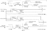
- FIG. 4 depicts example components and circuitry for the dual read channel architecture for SSW.
- a TBG read channel 402 is based on TBG clock 162.
- the read head analog signal 130 and BEMF signal 240 are also input to the TBG read channel 402.
- the BEMF signal 240 synchronizes two counters with the disk angular rotation-a wedge counter (WCNTR) 406 and a single counter that is a number-of-wedge counter (NWCNTR) 408.
- the TBG clock 162 signal flows into wedge counter 406 which is a counter (e.g., sawtooth counter) that tracks angular position inside of a wedge or angular slice of the disk.
- WNTR disk angular rotation-a wedge counter
- NWCNTR number-of-wedge counter
- the wedge counter 406 signal flows into the number-of-wedge counter 408 which is a single counter (e.g., stepper counter) that tracks which wedge the read head is in as a measure of angular position.
- Both the wedge counter 406 and the single number-of-wedge counter 408 output digital signals to the microprocessor or location tracking architecture that give the read heads angular position on the disk.
- the read head analog signal 130 is also processed in the TBG read channel 402.
- a bandpass filter 410 selects the portion of the read head analog signal 130 at the coarse spiral frequency.
- the bandpass filter 410 selects the frequency of the tracked data instead.
- the filtered read head signal then passes into an analog to digital converter (ADC) 414.
- ADC analog to digital converter
- the coarse spiral signal is converted from an analog signal to a digital signal at the ADC 414.
- the ADC 414 removes the envelope shape from the coarse spiral signal where the pyramidal shape is a feature of the read head passing over the spiral track obliquely.
- the digital coarse spiral signal then passes into a spiral demodulation engine 412.
- the spiral demodulation engine 412 separates the spiral synchmark data from the carrier frequency, where the carrier frequency is the coarse spiral frequency or another frequency.
- the demodulation engine 412 outputs the coarse spiral synchmark data to the microprocessor or location tracking architecture to determine the read head position (radial and angular components of position) on the disk.
- the coarse spiral synchmark data corresponds to time data written on the disk embedded in the coarse reference spiral.
- the processor extracts both radial and angular position information from the coarse spiral synchmark signal.
- An SFG read channel 452 is based on the SFG clock 164.
- the read head analog signal 430 and BEMF signal 240 are also input to the SFG read channel 452.
- the BEMF signal 240 synchronizes two counters with disk angular rotation-a wedge counter (WCNTR) 456 and a single counter that is a number-of-wedge counter (NWCNTR) 458.
- the SFG clock 164 signal flows into wedge counter 456 (e.g., a sawtooth counter) and tracks angular position inside of a wedge or angular slice of the disk.
- the wedge counter 456 signal flows into the number-of-wedge counter 458, which is a single counter (e.g., a stepper counter) that tracks which wedge the read head is in as a measure of angular position.
- Both the wedge counter 456 and the single number-of-wedge counter 458 output digital signals to the microprocessor or location tracking architecture that give the read heads angular position on the disk.
- Wedge counter 406 and wedge counter 456 depend on different clocks, and so will not count at the same frequency.
- the two number-of-wedge counters-the single number-of-wedge counter 408 and the single number-of-wedge counter 458- also depend upon different clocks, so will not count at the same frequency.
- a read head analog signal 430 is also processed in the SFG read channel 452.
- the read head analog signal 430 can be the read head analog signal 130 or can be the read head analog signal from a different read head.
- a bandpass filter 460 selects the portion of the read head analog signal 430 at the intermediate spiral frequency.
- the filtered read head signal then passes into an analog to digital converter (ADC) 464.
- the intermediate spiral signal is then converted from an analog to a digital signal at the ADC 464.
- the ADC 464 removes the envelope shape from the intermediate spiral signal where the pyramidal shape arises when the read head passes over the intermediate spiral track obliquely.
- the ADC 464 outputs the intermediate spiral signal to a spiral demodulation engine 462.
- the spiral demodulation engine 462 separates the intermediate spiral synchmark data from the carrier frequency, where the carrier frequency is the intermediate spiral frequency
- the intermediate spiral synchmark data is then output to the microprocessor or location tracking architecture to determine the radial and angular position of the read head on the disk.
- the intermediate spiral synchmark data corresponds to time data generated during the intermediate spiral writing process and embedded into the intermediate reference spirals.
- the processor extracts both radial and angular position information from the intermediate spiral synchmark signal.
- FIG. 5 is a flowchart of example operations for intermediate reference spiral frequency dependent writing of zoned concentric servo wedges.
- the controller synchronizes a first clock (TBG clock) and a second clock (SFG clock) to disk rotation using the BEMF signal generated by the disk motor to adjust a frequency offset multiplier (Foffset).
- a first read channel (TBG read channel) dependent on the first read clock and a second read channel (SFG read channel) dependent on the second clock both contain a set of two positional counters: NWCNTR (a single counter that is a number-of-wedge counter) and WCNTR (wedge counter). These counters run at the channel clock speed and output a set of counter values used to track angular position of the disk in the synchronized read channels. This allows the controller to track a time stamp for the BEMF signal.
- Foffset is calculated and adjusted to maintain locking of the clock frequencies to disk rotation on the order of once per disk rotation. The synchronization lock of the first clock and the second clock to disk rotation is maintained throughout the SSW process, but the source of the offset multiplier changes throughout the process.
- the controller synchronizes both the frequency offset multiplier, Foffset, and the application of the frequency multipliers for both the first and second clock via a "clock input synchronization path," which is logic that synchronizes the communication or transmission of the Foffset and multipliers to parallel clock multipliers to generate the first and second clocks.
- Both the first and second clock function as frequency multiples of a reference frequency, FREF, and are therefore in parallel.
- the first clock is a phase locked loop frequency multiple of the reference frequency multiplied by a first frequency multiplier (TBG_MUL) and the frequency offset multiplier Foffset.
- the second clock is a phase locked loop frequency multiple of the reference frequency multiplied by a second frequency multiplier (SFG_MUL) and the frequency offset multiplier Foffset.
- the controller updates Foffset (continually), and both TBG_MUL and SFG_MUL (when new values are selected) during SSW.
- Foffset continuously
- SFG_MUL when new values are selected
- the counters NWCNTR and WCNTR are reset for the new clock frequency and re-synchronized to disk rotation so that the first and second clock maintain synchronization with each other and disk rotation.
- the controller locks on to the coarse reference spiral that is the first set of positional data written to the blank disk.
- the controller first selects the frequency of the coarse reference spiral and determines a value for the first clock frequency multiplier (TBG MUL) that, when applied to the reference frequency, produces a first clock frequency equal to the coarse reference spiral frequency.
- the first clock is locked by PLL to the coarse reference spiral frequency.
- the controller uses the first read channel to "seek" (or detect) and “learn” (or store) locations of each of the coarse reference spiral tracks as a function of the first read channel counter signals. Once the coarse reference spiral tracks are located and the locations are learned, the disk synchronization lock source is switched from the BEMF signal to the coarse reference spiral frequency and the clock input synchronization path is reset. Angular and radial position of the read head on the disk is tracked in the first read channel via spiral synchmark data and spiral amplitude signals.
- the controller selects a servo zone (grouping of concentric tracks associated with a same servo pattern frequency).
- the controller implements a loop in order to write zoned intermediate reference spirals over the disk.
- the controller generates zones with constant intermediate reference frequency-annular zones where the intermediate reference frequency is constant-based on predetermined servo zones.
- the controller determines zones for the intermediate reference frequency that are identical to the selected zones for the servo wedge pattern frequency-i.e. there is an exact match of intermediate reference frequency zones and servo zones. There may be many zones over the surface of the disk. Zones more proximate to the outer diameter of a disk can have a greater frequency or frequencies than those zones closer to the inner diameter of the disk.
- the controller determines a frequency for the intermediate reference spiral in the selected servo zone.
- the intermediate reference spiral frequency and the coarse reference spiral frequency complete a whole number of clock cycles for one disk rotation, but the controller can select an intermediate reference spiral frequency that is any multiple of the reference frequency that satisfies that condition.
- the final written servo pattern in a zone depends upon the intermediate reference frequency, so the controller selects an intermediate reference spiral frequency for a zone based on the selected servo (pattern) frequency for that zone.
- the servo pattern frequency can be output at the same intermediate reference spiral frequency, or at double the intermediate reference spiral frequency because of built in redundancy in the intermediate reference spiral frequency.
- each written symbol uses four clock cycles.
- the servo wedge pattern frequency only uses two clock cycles per written symbol, which produces a built-in twofold frequency multiplication.
- the frequency of the servo wedge pattern in the zone can be equal to the intermediate reference spiral frequency or a multiple (e.g., twice) of the intermediate reference spiral frequency.
- the controller sets the second clock and its corresponding read channel to the intermediate reference spiral frequency for the selected zone.
- the controller selects a second frequency multiplication factor (SFG_MUL) to set the second clock frequency to the selected intermediate reference spiral.
- the clock input synchronization path is updated so that the counters WCNTR and WNCNTR in both read channels are synchronized to disk rotation via Foffset calculated in the first read channel for disk rotation based on the coarse reference frequency signal.
- the second clock frequency remains locked to the intermediate reference spiral frequency while the controller is writing the selected zone.
- the controller writes a set of intermediate reference spirals in the selected zone. Because the counters of the first read channel (which is tracking position), and the counters of the second read channel (set to the intermediate reference frequency) are synchronized, the controller generates the intermediate reference spirals based on the location positions encoded by the coarse reference spirals and read in the first read channel. The controller produces intermediate reference spiral synchmark data based on read head location tracking in the first read channel, and outputs that signal at the second clock frequency to the write head. The location data for the intermediate reference spirals is refined and more accurate than the location data written in the coarse reference spiral, which was written based on location data produced by the less accurate BEMF signal. The controller stops the writing process at the selected zone boundary.
- the intermediate reference spiral is also a ramped reference spiral.
- the process of writing a ramped reference spiral(s) from a first reference spiral is also called ramped spiral servo self-write or RSSW.
- RSSW is the process by which a ramped reference spiral is written to a disk using positional data read in a channel with a clock synchronized to disk rotation (by Foffset generated via tracking the first reference spiral).
- the controller checks the servo zones for intermediate reference spiral completeness. If the controller has written intermediate reference spirals in all the zones on the disk and no zones remain for intermediate reference spiral writing, the controller ends the servo zone loop and the SSW process continues to block 517 where a new servo zone is selected. If, however, zones remain unwritten, flow continues to block 506 and the controller initiates another loop to continue writing intermediate reference spirals across servo zones.
- the controller selects a servo zone (a zone of constant servo wedge pattern frequency).
- the controller implements a loop in order to write zones of servo wedge patterns across the disk.
- the controller determines these servo zones before the controller writes the intermediate reference spiral.
- the controller selects a servo zone which corresponds to a written intermediate reference spiral frequency and to a selected servo pattern frequency.
- the relationship between the intermediate reference spiral frequency and the selected servo wedge pattern frequency is governed by the number of clock cycles necessary to write a symbol in the intermediate reference spiral and the servo wedge pattern.
- the controller determines the intermediate reference spiral frequency for the selected zone.
- the intermediate reference spiral is already written in the selected servo zone.
- the controller sets the second clock to the intermediate reference spiral frequency using a frequency multiplier (SFG MUL).
- the controller synchronizes the clocks via the clock input synchronization path updated with the new frequency multiplier.
- the controller Using the second read channel (SFG read channel), the controller then seeks and learns the location of the intermediate spiral in relation to disk angular and radial position.
- the controller detects the intermediate reference spiral synchmark data and learns the locations of the intermediate reference spirals on the disk by comparing the intermediate reference spiral synchmark data to the positional data transmitted by the wedge counter signal and the signal from the single number-of-wedge counter (which tracks cumulative number of wedges counted).
- the controller selects the intermediate reference spirals to calculate Foffset and lock both clocks to disk rotation.
- the controller resets and synchronizes counters WCNTR and NWCNTR via the clock input synchronization path.
- the controller tracks the location of the coarse reference spirals with the first read channel (TBG read channel), where the first clock remains set to the coarse reference spiral frequency, and the location of the intermediate reference spirals with the second read channel.
- the controller generates the servo wedge patterns (or concentric servo wedges) from predetermined servo wedge data at the servo wedge pattern frequency.
- the servo wedge pattern frequency is related to the second clock frequency (the intermediate reference spiral frequency) by the number of clock cycles that constitute a written symbol. If the written symbols of the intermediate reference spiral require four clock cycles, but the written symbols of the servo wedge pattern require two clock cycles, the servo wedge pattern written frequency can be double that of the intermediate reference spiral frequency.
- the use of parallel clocks allows the servo wedge sector data to be written at a stepped-up frequency relative to the intermediate reference spiral frequency. By increasing the angular frequency of data at the outer diameter, the total area occupied by the servo wedge sectors can be reduced.
- servo wedge data are used for maintaining read head positioning, the servo data occupy valuable surface area that cannot be used for written data. So, minimizing size of the space occupied by servo data increases available data storage area
- the data contained in a servo wedge sector (servo burst alignment marks, track data, etc.) is predetermined by the HDD parameters.
- the controller maintains positional lock on the disk via tracking of the intermediate reference spiral synchmark data in the second read channel.
- the controller writes the servo wedge pattern in servo wedge sectors in the selected zone via output to the write head at the servo wedge pattern frequency.
- the controller writes all the servo wedge sector data across the servo zone.
- the controller determines whether servo wedge sector writing is complete. If the servo wedge sector data are written in all the zones the servo zone loop ends and the SSW process ends. If, however, there remain zones without written servo wedge sector data, the SSW process is continued at block 527.
- the controller switches the source of Foffset that locks both parallel clocks to disk rotation.
- the controller selects the coarse reference spiral as tracked in the first read channel (the TBG read channel) and uses the location of the coarse reference spiral to calculate Foffset and lock the clocks to disk rotation.
- the coarse reference spiral contains synchmark data at a constant frequency over the entire disk and can be tracked over all zones. The flow then continues to block 517 where new servo zone is selected in the servo zone loop.
- Figure 6 is a flowchart of example operations for reference spiral frequency independent writing of zoned concentric servo wedges. Since the servo wedge pattern frequencies are independent of the intermediate reference spiral frequency, the coarse reference spiral will be reacquired when switching between zones during servo wedge sector writing.
- the HDD microprocessor or controller implements the multi-frequency workflow 600.
- the controller synchronizes a first clock (TBG clock) and a second clock (SFG clock) to disk rotation using the BEMF signal to adjust a frequency offset multiplier (Foffset).
- a first read channel (TBG read channel) dependent on the first read clock and a second read channel (SFG read channel) dependent on the second clock both contain positional counters: NWCNTR (the single counter that is a number-of-wedge counter) and WCNTR (the wedge counter). These counters run at the channel clock speed and output a set of counter values used to track angular position of the disk in the synchronized read channels.
- Foffset is calculated and adjusted to maintain locking of the clock frequencies to disk rotation on the order of once per disk rotation. The synchronization lock of the first clock and the second clock to disk rotation is maintained throughout the SSW process, but the source of the offset multiplier changes throughout the process.
- the controller synchronizes both the frequency offset multiplier, Foffset, and the application of the frequency multipliers for both the first and second clock via the "clock input synchronization path".
- Both the first and second clock function as in-parallel frequency multiples of a reference frequency, FREF.
- the first clock is a phase locked loop frequency multiple of the reference frequency multiplied by a first frequency multiplier (TBG_MUL) and the frequency offset multiplier Foffset.
- TBG_MUL first frequency multiplier
- FSG_MUL second frequency multiplier
- the controller updates Foffset (continually), and both TBG_MUL and SFG_MUL (when new values are selected) during SSW.
- the counters NWCNTR and WCNTR are reset for the new clock frequency and re-synchronized to disk rotation so that the first and second clock maintain synchronization with each other and disk rotation.
- the controller locks on to the coarse reference spiral that is the first set of positional data written to the blank disk.
- the controller first selects the frequency of the coarse reference spiral and determines a value for the first clock frequency multiplier (TBG MUL) that, when applied to the reference frequency, produces a first clock frequency equal to the coarse reference spiral frequency.
- the first clock is locked by PLL to the coarse reference spiral frequency.
- the controller uses the first read channel to "seek" (or detect) and “learn” (or store) locations of each of the coarse reference spiral tracks as a function of the first read channel counter signals. Once the coarse reference spiral tracks are located and the locations are learned, the disk synchronization lock is switched from the BEMF signal to the coarse reference spiral frequency and the clock input synchronization path is reset. Angular and radial position of the read head on the disk is tracked in the first read channel via spiral synchmark and spiral amplitude signals.
- the controller selects a servo zone.
- the controller implements a loop in order to write zoned intermediate reference spirals over the disk.
- the controller generates zones with constant intermediate reference frequency-annular zones where the intermediate reference frequency is constant-based on predetermined servo zones.
- the controller determines zones for the intermediate reference frequency that are identical to the selected zones for the servo pattern frequency-i.e. there is an exact match of intermediate reference frequency zones and servo zones. There may be many zones over the surface of the disk. Zones more proximate to the outer diameter of a disk can have a greater frequency or frequencies than those zones closer to the inner diameter of the disk.
- the controller determines a frequency for the intermediate reference spiral in the selected servo zone.
- the intermediate reference spiral frequency and the coarse reference spiral frequency complete a whole number of clock cycles for one disk rotation, but the controller can select an intermediate reference spiral frequency that is any multiple of the reference frequency that satisfies that condition.
- the final written servo pattern in a zone does not depend upon the intermediate reference frequency, so the controller determines an intermediate reference spiral frequency for a zone based on written data density limits, or other procedural or hardware limitations.
- the controller sets the second clock and its corresponding read channel to the intermediate reference spiral frequency for the selected zone.
- the controller selects a second frequency multiplication factor (SFG_MUL) to set the second clock frequency to the selected intermediate reference spiral.
- the clock input synchronization path is updated so that the counters WCNTR and WNCNTR in both read channels are synchronized to disk rotation via Foffset calculated in the first read channel for disk rotation based on the coarse reference frequency signal.
- the second clock frequency remains locked to the intermediate reference spiral frequency while the controller is writing the selected zone.
- the controller writes a set of intermediate reference spirals in the selected zone. Because the counters of the first read channel (which is tracking position), and the counters of the second read channel (set to the intermediate reference frequency) are synchronized, the controller generates the intermediate reference spirals based on the location positions encoded by the coarse reference spirals and read in the first read channel. The controller produces intermediate reference spiral synchmark data based on read head location tracking in the first read channel, and outputs that signal at the second clock frequency to the write head. The location data for the intermediate reference spirals is refined and more accurate than the location data written in the coarse reference spiral, which was written based on location data produced by the less accurate BEMF signal. The controller stops the writing process at the selected zone boundary.
- the controller checks the servo zones for intermediate reference spiral completeness. If the controller has written intermediate reference spirals in all the zones on the disk and no zones remain for intermediate reference spiral writing, the controller ends the servo zone loop and the SSW process continues to block 617 where a new servo zone is selected. If, however, zones remain unwritten, flow continues to block 606 and the controller initiates another loop to continue writing intermediate reference spirals across servo zones.
- the controller selects a servo zone (a zone of constant servo wedge pattern frequency).
- the controller implements a loop in order to write zones of servo wedge patterns across the disk.
- the controller determines these servo zones before the controller writes the intermediate reference spiral and uses the same servo zones to zone the servo wedge pattern frequency.
- the controller selects a servo zone which corresponds to a written intermediate reference spiral frequency and to a servo pattern frequency.
- the first clock is synchronized to the coarse reference spiral frequency at completion of the intermediate reference spiral writing.
- the first clock (TBG clock) is resynchronized to the coarse reference spiral frequency before it starts another loop at block 617.
- the controller uses the coarse reference spiral tracked in the first read channel to move the read head between servo zone in order to locate the selected servo zone at the determined intermediate reference frequency.
- the controller learns the location of the coarse reference spiral data by reading the coarse reference spiral synchmark data and comparing to the angular position data in the first read channel, which is a function of WCNTR and NWCNTR output signals.
- the parallel clocks are locked to disk rotation via Foffset calculated from the coarse reference spiral. From the coarse spiral location data, the controller locates the intermediate spiral in the selected zone.
- the controller determines a servo wedge pattern frequency for the selected zone.
- the first clock (TBG clock) will be reset to the servo wedge pattern frequency in the selected servo zone.
- the servo wedge pattern frequency can be any frequency sufficient for a complete disk rotation to contain only whole symbols. For an example in which a whole symbol is written in four clock cycles, the relationship below holds:
- the controller acquires the intermediate reference spiral in the selected zone.
- the controller phase loop locks the second clock to the intermediate reference clock frequency by selecting the second frequency multiplier (SFG_MUL) to multiply the reference frequency FREF.
- the controller learns the location of the intermediate reference spiral data by reading, in the second read channel, the intermediate reference spiral synchmark data and comparing to the angular position data in the second read channel, which is a function of WCNTR and NWCNTR output signals.
- the parallel clocks are then locked to disk rotation via Foffset calculated from the intermediate reference spiral.
- the parallel clocks are locked to disk rotation and each other using the clock input synchronization path based off the frequency offset calculated from the intermediate reference spiral.
- the controller maps the servo zone using the synchronized clocks.
- the controller implements a PLL to lock the first clock (TBG clock) to the servo (wedge) pattern frequency determined for the selected servo zone.
- the controller outputs a first frequency multiplier (TBG_MUL) that multiplies the reference frequency FREF up to the selected servo pattern frequency.
- TSG_MUL first frequency multiplier
- the first read clock channel no longer tracks information about the location of the coarse reference spiral.
- the locational tracking and calculation of Foffset occur in the second read channel at the intermediate reference spiral frequency.
- the counters WCNTR and NWCNTR in both read channels are synchronized at the new values of the frequency multipliers.
- the controller writes the servo wedge sectors in the selected servo zone.
- the location of the read head is determined in the second read channel (SFG read channel) from the spiral synchmark data of the intermediate reference spirals as tracked by the positional wedge counters WCNTR and NWCNTR.
- the concentric servo pattern (servo wedge pattern) written in the servo wedge sector (servo burst alignment marks, track data, etc.) is predetermined by the HDD parameters.
- the use of parallel clocks allows the servo wedge sector data to be written at a stepped-up frequency relative to the intermediate reference spiral frequency, which itself is stepped up from the coarse reference spiral frequency. By increasing the angular frequency of data at the outer diameter, the total area occupied by the servo wedge sectors can be reduced.
- the controller maintains positional lock on the disk via tracking of the intermediate reference spiral synchmark data in the second read channel. Foffset, which locks the clocks to disk rotation, is calculated from the refined positional data of the intermediate reference frequency.
- the controller writes the servo wedge pattern in servo wedge sectors in the selected zone by outputting the servo wedge patterns to the write head at the servo wedge pattern frequency which is maintained by the first clock (TBG clock).
- TBG clock first clock
- the controller determines whether servo wedge sector writing is complete. If the servo wedge sector data are written in all the zones the servo zone loop ends and the SSW process ends. If, however, there remain zones without written servo wedge sector data, the SSW process is continued at block 627.
- the controller resets the first clock to the coarse reference spiral frequency.
- the controller resets the first frequency multiplier (TBG_MUL) and selects a new frequency multiplier such that the first clock frequency is phase loop locked to the coarse reference spiral frequency.
- the controller updates clock input synchronization lock based on the new multiplier values.
- the controller uses the coarse reference spiral as tracked in the first read channel to move the read head between servo zones in order to locate the selected servo zone at the determined intermediate reference frequency.
- the controller learns the location of the coarse reference spiral data by reading the coarse reference spiral synchmark data and comparing to the angular position data in the first read channel (from WCNTR and NWCNTR output signals).
- the parallel clocks are locked to disk rotation via Foffset calculated from the coarse reference spiral. From the coarse spiral location data, the controller locates the intermediate spiral in the selected zone.
- the multi-frequency workflow 600 allows for more freedom in concentric servo (servo wedge pattern) frequency. However, this freedom is obtained by reacquiring the coarse spiral at each new intermediate spiral frequency zone during concentric servo writing.
- aspects of the disclosure may be embodied as a system, method or program code/instructions stored in one or more machine-readable media. Accordingly, aspects may take the form of hardware, software (including firmware, resident software, micro-code, etc.), or a combination of software and hardware aspects that may all generally be referred to herein as a "circuit,” “module” or “system.”
- the functionality presented as individual modules/units in the example illustrations can be organized differently in accordance with any one of platform (operating system and/or hardware), application ecosystem, interfaces, programmer preferences, programming language, administrator preferences, etc.
- the machine-readable medium may be a machine-readable signal medium or a machine-readable storage medium.
- a machine-readable storage medium may be, for example, but not limited to, a system, apparatus, or device, that employs any one of or combination of electronic, magnetic, optical, electromagnetic, infrared, or semiconductor technology to store program code.
- machine readable storage medium More specific examples (a non-exhaustive list) of the machine readable storage medium would include the following: a portable computer diskette, a hard disk, a random access memory (RAM), a read-only memory (ROM), an erasable programmable read-only memory (EPROM or Flash memory), a portable compact disc read-only memory (CD-ROM), an optical storage device, a magnetic storage device, or any suitable combination of the foregoing.
- a machine-readable storage medium may be any tangible medium that can contain, or store a program for use by or in connection with an instruction execution system, apparatus, or device.
- a machine-readable storage medium is not a machine-readable signal medium.
- a machine-readable signal medium may include a propagated data signal with machine readable program code embodied therein, for example, in baseband or as part of a carrier wave. Such a propagated signal may take any of a variety of forms, including, but not limited to, electro-magnetic, optical, or any suitable combination thereof.
- a machine-readable signal medium may be any machine-readable medium that is not a machine-readable storage medium and that can communicate, propagate, or transport a program for use by or in connection with an instruction execution system, apparatus, or device.
- Program code embodied on a machine-readable medium may be transmitted using any appropriate medium, including but not limited to wireless, wireline, optical fiber cable, RF, etc., or any suitable combination of the foregoing.
- the program code/instructions may also be stored in a machine readable medium that can direct a machine to function in a particular manner, such that the instructions stored in the machine readable medium produce an article of manufacture including instructions which implement the function/act specified in the flowchart and/or block diagram block or blocks.
- the term "or” is inclusive unless otherwise explicitly noted. Thus, the phrase “at least one of A, B, or C” is satisfied by any element from the set ⁇ A, B, C ⁇ or any combination thereof, including multiples of any element.
Landscapes
- Engineering & Computer Science (AREA)
- Signal Processing (AREA)
- Moving Of The Head To Find And Align With The Track (AREA)
Applications Claiming Priority (2)
| Application Number | Priority Date | Filing Date | Title |
|---|---|---|---|
| US201862782211P | 2018-12-19 | 2018-12-19 | |
| US16/715,559 US10832716B2 (en) | 2018-12-19 | 2019-12-16 | Zone self servo writing with synchronized parallel clocks |
Publications (1)
| Publication Number | Publication Date |
|---|---|
| EP3671744A1 true EP3671744A1 (de) | 2020-06-24 |
Family
ID=68944606
Family Applications (1)
| Application Number | Title | Priority Date | Filing Date |
|---|---|---|---|
| EP19217455.5A Pending EP3671744A1 (de) | 2018-12-19 | 2019-12-18 | Zonen-self-servo-schreibverfahren mit synchronisierten paralleltaktgebern |
Country Status (5)
| Country | Link |
|---|---|
| US (1) | US10832716B2 (de) |
| EP (1) | EP3671744A1 (de) |
| KR (1) | KR102699500B1 (de) |
| CN (1) | CN111341354B (de) |
| TW (1) | TWI846783B (de) |
Families Citing this family (9)
| Publication number | Priority date | Publication date | Assignee | Title |
|---|---|---|---|---|
| US10734016B2 (en) | 2018-08-21 | 2020-08-04 | Marvell Asia Pte, Ltd. | Pulse-based writing for magnetic storage media |
| US12197738B2 (en) | 2019-01-31 | 2025-01-14 | Marvell Asia Pte, Ltd. | Health management for magnetic storage media |
| US11450348B2 (en) | 2019-01-31 | 2022-09-20 | Marvell Asia Pte, Ltd. | Health management for magnetic storage media |
| CN116312657A (zh) | 2019-02-26 | 2023-06-23 | 马维尔亚洲私人有限公司 | 用于磁存储介质的码字交织 |
| US10971187B2 (en) * | 2019-03-11 | 2021-04-06 | Marvell Asia Pte, Ltd. | Constant-density writing for magnetic storage media |
| US11417361B2 (en) | 2020-08-19 | 2022-08-16 | Marvell Asia Pte, Ltd. | Write timing for RRO field in a constant density servo system |
| US11430481B2 (en) * | 2020-09-09 | 2022-08-30 | Marvell Asia Pte, Ltd. | Dual-surface self-servo-write for storage device |
| US12198724B1 (en) | 2022-07-25 | 2025-01-14 | Marvell Asia Pte, Ltd. | Codeword interleaving over magnetic media surfaces |
| US12206753B1 (en) | 2022-08-25 | 2025-01-21 | Marvell Asia Pte Ltd | Unified time base for storage device data channel |
Citations (4)
| Publication number | Priority date | Publication date | Assignee | Title |
|---|---|---|---|---|
| US7688534B1 (en) * | 2008-12-11 | 2010-03-30 | Western Digital Technologies, Inc. | Extracting repeatable phase error from a spindle motor back EMF signal to generate a servo write clock |
| US8027117B1 (en) * | 2008-08-25 | 2011-09-27 | Marvell International Ltd. | Zone servo writing using self servo writing |
| US8508879B1 (en) * | 2010-01-21 | 2013-08-13 | Marvell International Ltd. | Write clock rephase for magnetic recording device |
| US8687308B1 (en) * | 2010-06-02 | 2014-04-01 | Marvell International Ltd. | Zone servo write with multi-frequency self-spiral write |
Family Cites Families (19)
| Publication number | Priority date | Publication date | Assignee | Title |
|---|---|---|---|---|
| US5068755A (en) * | 1990-06-01 | 1991-11-26 | Micropolis Corporation | Sector pulse generator for hard disk drive assembly |
| JP3463737B2 (ja) * | 1998-12-08 | 2003-11-05 | 株式会社田村電機製作所 | 磁気カードリーダ |
| JP2002050084A (ja) * | 2000-07-28 | 2002-02-15 | Fujitsu Ltd | 原盤露光装置 |
| JP4170707B2 (ja) * | 2002-08-30 | 2008-10-22 | 富士通株式会社 | サーボトラック書込装置及び方法 |
| US7098707B2 (en) * | 2004-03-09 | 2006-08-29 | Altera Corporation | Highly configurable PLL architecture for programmable logic |
| US7230789B1 (en) | 2004-04-08 | 2007-06-12 | Maxtor Corporation | Method and apparatus for performing a self-servo write operation in a disk drive using spiral servo information |
| US7751144B1 (en) * | 2004-07-15 | 2010-07-06 | Marvell International Ltd. | Self-servo-write using ramp-tracks |
| US7199959B1 (en) * | 2004-12-13 | 2007-04-03 | Western Digital Technologies, Inc. | Repeatable timing error correction system for use in a servo writer |
| JP4689426B2 (ja) * | 2005-09-30 | 2011-05-25 | 富士フイルム株式会社 | 光ディスクシステム、光ディスク記録装置、画像描画方法、及び光ディスク |
| US7619846B2 (en) | 2006-05-19 | 2009-11-17 | Maxtor Corporation | Self-servo writing using staged patterning |
| US7675703B2 (en) * | 2007-06-08 | 2010-03-09 | Hitachi Global Storage Technologies Netherlands B.V. | Magnetic recording disk drive with patterned media and system for clocking write data |
| US8077422B1 (en) | 2007-08-15 | 2011-12-13 | Marvell International Ltd. | Writing spirals based on servo tracks of a different sample rate |
| US20090086357A1 (en) * | 2007-09-28 | 2009-04-02 | Toshiba America Information Systems, Inc. | In drive written spirals for self servo writing |
| JP4282735B1 (ja) * | 2007-12-27 | 2009-06-24 | 株式会社東芝 | ディスクドライブ装置およびサーボ書込み方法 |
| US7733151B1 (en) * | 2008-12-08 | 2010-06-08 | Texas Instruments Incorporated | Operating clock generation system and method for audio applications |
| US8325433B2 (en) * | 2011-01-19 | 2012-12-04 | Lsi Corporation | Systems and methods for reduced format data processing |
| US8743504B1 (en) * | 2012-07-25 | 2014-06-03 | Western Digital Technologies, Inc. | Servoing on zoned concentric servo sectors of a first disk surface to write a spiral servo track to a second disk surface |
| US9431052B2 (en) | 2014-06-26 | 2016-08-30 | Marvell World Trade Ltd. | Two dimensional magnetic recording systems, devices and methods |
| US20160358621A1 (en) * | 2015-06-03 | 2016-12-08 | HGST Netherlands B.V. | Self-Servo Write Non-Reference Head Position Measuring |
-
2019
- 2019-12-16 US US16/715,559 patent/US10832716B2/en active Active
- 2019-12-18 TW TW108146475A patent/TWI846783B/zh active
- 2019-12-18 EP EP19217455.5A patent/EP3671744A1/de active Pending
- 2019-12-18 KR KR1020190169981A patent/KR102699500B1/ko active Active
- 2019-12-19 CN CN201911320848.1A patent/CN111341354B/zh active Active
Patent Citations (4)
| Publication number | Priority date | Publication date | Assignee | Title |
|---|---|---|---|---|
| US8027117B1 (en) * | 2008-08-25 | 2011-09-27 | Marvell International Ltd. | Zone servo writing using self servo writing |
| US7688534B1 (en) * | 2008-12-11 | 2010-03-30 | Western Digital Technologies, Inc. | Extracting repeatable phase error from a spindle motor back EMF signal to generate a servo write clock |
| US8508879B1 (en) * | 2010-01-21 | 2013-08-13 | Marvell International Ltd. | Write clock rephase for magnetic recording device |
| US8687308B1 (en) * | 2010-06-02 | 2014-04-01 | Marvell International Ltd. | Zone servo write with multi-frequency self-spiral write |
Also Published As
| Publication number | Publication date |
|---|---|
| US20200202893A1 (en) | 2020-06-25 |
| TW202040565A (zh) | 2020-11-01 |
| KR102699500B1 (ko) | 2024-08-30 |
| CN111341354A (zh) | 2020-06-26 |
| KR20200077442A (ko) | 2020-06-30 |
| CN111341354B (zh) | 2022-11-29 |
| US10832716B2 (en) | 2020-11-10 |
| TWI846783B (zh) | 2024-07-01 |
Similar Documents
| Publication | Publication Date | Title |
|---|---|---|
| US10832716B2 (en) | Zone self servo writing with synchronized parallel clocks | |
| US8743504B1 (en) | Servoing on zoned concentric servo sectors of a first disk surface to write a spiral servo track to a second disk surface | |
| US8508879B1 (en) | Write clock rephase for magnetic recording device | |
| US8331050B1 (en) | Patterned magnetic media synchronization systems | |
| US8780470B1 (en) | Disk drive adjusting digital phase locked loop over sector data with frequency induced phase error measured over preamble | |
| US8027117B1 (en) | Zone servo writing using self servo writing | |
| US7715138B1 (en) | Disk drive estimating a servo zone after synchronously detecting a servo sync mark | |
| US8786979B1 (en) | Self servo write process for discrete track media | |
| US7298574B1 (en) | Servo writing a disk drive using correction values that attenuate phase error propagation | |
| US6943978B1 (en) | Servo writing a disk drive by synchronizing a servo write clock to a high frequency signal in a spiral track | |
| US7068459B1 (en) | Adjusting track density by changing PES algorithm when servo writing a disk drive from spiral tracks | |
| US8116023B1 (en) | Disk drive comprising preamble aligned zoned servo sectors | |
| US9013819B1 (en) | Write clock phase tracking for magnetic recording device | |
| US6084738A (en) | Writing servo information to a disc drive at a constant density | |
| US6738205B1 (en) | Self-writing of servo patterns in disk drives | |
| US8724245B1 (en) | Disk drive employing overlapping servo zones to facilitate servo zone crossing | |
| US7929238B1 (en) | Disk drive seeking with a fixed rate clock when crossing servo zones to facilitate zoned servo sectors | |
| US8213106B1 (en) | Zoned servo system | |
| US7453661B1 (en) | Servo writing a disk drive with a controlled overlap near the middle diameter of the disk | |
| US6118604A (en) | Constant density servo information in a disc drive | |
| US8780477B1 (en) | Disk drive adjusting servo timing to compensate for transient when crossing a servo zone boundary | |
| US6965489B1 (en) | Using an external spiral servo writer to write reference servo sectors and spiral tracks to a disk to facilitate writing product servo sectors to the disk | |
| US7256956B2 (en) | Propagation self servowrite using self-written spiral signals for in-process calibration | |
| US8687308B1 (en) | Zone servo write with multi-frequency self-spiral write | |
| US7835105B1 (en) | Propagation self servo write system and method for storage devices employing sector-servo scheme |
Legal Events
| Date | Code | Title | Description |
|---|---|---|---|
| PUAI | Public reference made under article 153(3) epc to a published international application that has entered the european phase |
Free format text: ORIGINAL CODE: 0009012 |
|
| STAA | Information on the status of an ep patent application or granted ep patent |
Free format text: STATUS: THE APPLICATION HAS BEEN PUBLISHED |
|
| AK | Designated contracting states |
Kind code of ref document: A1 Designated state(s): AL AT BE BG CH CY CZ DE DK EE ES FI FR GB GR HR HU IE IS IT LI LT LU LV MC MK MT NL NO PL PT RO RS SE SI SK SM TR |
|
| AX | Request for extension of the european patent |
Extension state: BA ME |
|
| STAA | Information on the status of an ep patent application or granted ep patent |
Free format text: STATUS: REQUEST FOR EXAMINATION WAS MADE |
|
| 17P | Request for examination filed |
Effective date: 20201023 |
|
| RBV | Designated contracting states (corrected) |
Designated state(s): AL AT BE BG CH CY CZ DE DK EE ES FI FR GB GR HR HU IE IS IT LI LT LU LV MC MK MT NL NO PL PT RO RS SE SI SK SM TR |
|
| STAA | Information on the status of an ep patent application or granted ep patent |
Free format text: STATUS: EXAMINATION IS IN PROGRESS |
|
| 17Q | First examination report despatched |
Effective date: 20230619 |