EP3671399A1 - Bestimmungsverfahren eines bevorzugten minimalen leistungssollwerts, steuerungsverfahren einer vielzahl von wasserboilern und entsprechende vorrichtung - Google Patents
Bestimmungsverfahren eines bevorzugten minimalen leistungssollwerts, steuerungsverfahren einer vielzahl von wasserboilern und entsprechende vorrichtung Download PDFInfo
- Publication number
- EP3671399A1 EP3671399A1 EP19218815.9A EP19218815A EP3671399A1 EP 3671399 A1 EP3671399 A1 EP 3671399A1 EP 19218815 A EP19218815 A EP 19218815A EP 3671399 A1 EP3671399 A1 EP 3671399A1
- Authority
- EP
- European Patent Office
- Prior art keywords
- consumer
- determining
- power setpoint
- time
- water
- Prior art date
- Legal status (The legal status is an assumption and is not a legal conclusion. Google has not performed a legal analysis and makes no representation as to the accuracy of the status listed.)
- Granted
Links
- XLYOFNOQVPJJNP-UHFFFAOYSA-N water Substances O XLYOFNOQVPJJNP-UHFFFAOYSA-N 0.000 title claims abstract description 130
- 238000000034 method Methods 0.000 title claims abstract description 54
- 238000004519 manufacturing process Methods 0.000 claims description 18
- 238000009826 distribution Methods 0.000 claims description 11
- 238000004590 computer program Methods 0.000 claims description 4
- 230000006870 function Effects 0.000 description 14
- 238000007726 management method Methods 0.000 description 7
- 238000004891 communication Methods 0.000 description 6
- 238000009434 installation Methods 0.000 description 5
- 238000012550 audit Methods 0.000 description 4
- 238000010438 heat treatment Methods 0.000 description 3
- 230000008569 process Effects 0.000 description 3
- 239000006185 dispersion Substances 0.000 description 2
- 238000003860 storage Methods 0.000 description 2
- 230000004913 activation Effects 0.000 description 1
- 238000004378 air conditioning Methods 0.000 description 1
- 230000008901 benefit Effects 0.000 description 1
- 238000004364 calculation method Methods 0.000 description 1
- 230000009849 deactivation Effects 0.000 description 1
- 238000010616 electrical installation Methods 0.000 description 1
- 230000005611 electricity Effects 0.000 description 1
- 238000005338 heat storage Methods 0.000 description 1
- 238000012067 mathematical method Methods 0.000 description 1
- 238000005259 measurement Methods 0.000 description 1
- 238000002493 microarray Methods 0.000 description 1
- 239000003643 water by type Substances 0.000 description 1
Images
Classifications
-
- F—MECHANICAL ENGINEERING; LIGHTING; HEATING; WEAPONS; BLASTING
- F24—HEATING; RANGES; VENTILATING
- F24D—DOMESTIC- OR SPACE-HEATING SYSTEMS, e.g. CENTRAL HEATING SYSTEMS; DOMESTIC HOT-WATER SUPPLY SYSTEMS; ELEMENTS OR COMPONENTS THEREFOR
- F24D19/00—Details
- F24D19/10—Arrangement or mounting of control or safety devices
- F24D19/1006—Arrangement or mounting of control or safety devices for water heating systems
- F24D19/1051—Arrangement or mounting of control or safety devices for water heating systems for domestic hot water
- F24D19/1063—Arrangement or mounting of control or safety devices for water heating systems for domestic hot water counting of energy consumption
-
- G—PHYSICS
- G05—CONTROLLING; REGULATING
- G05D—SYSTEMS FOR CONTROLLING OR REGULATING NON-ELECTRIC VARIABLES
- G05D23/00—Control of temperature
- G05D23/19—Control of temperature characterised by the use of electric means
- G05D23/1919—Control of temperature characterised by the use of electric means characterised by the type of controller
- G05D23/1924—Control of temperature characterised by the use of electric means characterised by the type of controller using thermal energy, the availability of which is aleatory
-
- F—MECHANICAL ENGINEERING; LIGHTING; HEATING; WEAPONS; BLASTING
- F24—HEATING; RANGES; VENTILATING
- F24D—DOMESTIC- OR SPACE-HEATING SYSTEMS, e.g. CENTRAL HEATING SYSTEMS; DOMESTIC HOT-WATER SUPPLY SYSTEMS; ELEMENTS OR COMPONENTS THEREFOR
- F24D17/00—Domestic hot-water supply systems
- F24D17/0036—Domestic hot-water supply systems with combination of different kinds of heating means
- F24D17/0063—Domestic hot-water supply systems with combination of different kinds of heating means solar energy and conventional heaters
-
- F—MECHANICAL ENGINEERING; LIGHTING; HEATING; WEAPONS; BLASTING
- F24—HEATING; RANGES; VENTILATING
- F24D—DOMESTIC- OR SPACE-HEATING SYSTEMS, e.g. CENTRAL HEATING SYSTEMS; DOMESTIC HOT-WATER SUPPLY SYSTEMS; ELEMENTS OR COMPONENTS THEREFOR
- F24D19/00—Details
- F24D19/10—Arrangement or mounting of control or safety devices
- F24D19/1006—Arrangement or mounting of control or safety devices for water heating systems
- F24D19/1051—Arrangement or mounting of control or safety devices for water heating systems for domestic hot water
- F24D19/1057—Arrangement or mounting of control or safety devices for water heating systems for domestic hot water the system uses solar energy
-
- F—MECHANICAL ENGINEERING; LIGHTING; HEATING; WEAPONS; BLASTING
- F24—HEATING; RANGES; VENTILATING
- F24H—FLUID HEATERS, e.g. WATER OR AIR HEATERS, HAVING HEAT-GENERATING MEANS, e.g. HEAT PUMPS, IN GENERAL
- F24H15/00—Control of fluid heaters
- F24H15/10—Control of fluid heaters characterised by the purpose of the control
- F24H15/144—Measuring or calculating energy consumption
- F24H15/148—Assessing the current energy consumption
-
- F—MECHANICAL ENGINEERING; LIGHTING; HEATING; WEAPONS; BLASTING
- F24—HEATING; RANGES; VENTILATING
- F24H—FLUID HEATERS, e.g. WATER OR AIR HEATERS, HAVING HEAT-GENERATING MEANS, e.g. HEAT PUMPS, IN GENERAL
- F24H15/00—Control of fluid heaters
- F24H15/10—Control of fluid heaters characterised by the purpose of the control
- F24H15/144—Measuring or calculating energy consumption
- F24H15/152—Forecasting future energy consumption
-
- F—MECHANICAL ENGINEERING; LIGHTING; HEATING; WEAPONS; BLASTING
- F24—HEATING; RANGES; VENTILATING
- F24H—FLUID HEATERS, e.g. WATER OR AIR HEATERS, HAVING HEAT-GENERATING MEANS, e.g. HEAT PUMPS, IN GENERAL
- F24H15/00—Control of fluid heaters
- F24H15/10—Control of fluid heaters characterised by the purpose of the control
- F24H15/156—Reducing the quantity of energy consumed; Increasing efficiency
-
- F—MECHANICAL ENGINEERING; LIGHTING; HEATING; WEAPONS; BLASTING
- F24—HEATING; RANGES; VENTILATING
- F24D—DOMESTIC- OR SPACE-HEATING SYSTEMS, e.g. CENTRAL HEATING SYSTEMS; DOMESTIC HOT-WATER SUPPLY SYSTEMS; ELEMENTS OR COMPONENTS THEREFOR
- F24D2200/00—Heat sources or energy sources
- F24D2200/02—Photovoltaic energy
-
- F—MECHANICAL ENGINEERING; LIGHTING; HEATING; WEAPONS; BLASTING
- F24—HEATING; RANGES; VENTILATING
- F24D—DOMESTIC- OR SPACE-HEATING SYSTEMS, e.g. CENTRAL HEATING SYSTEMS; DOMESTIC HOT-WATER SUPPLY SYSTEMS; ELEMENTS OR COMPONENTS THEREFOR
- F24D2200/00—Heat sources or energy sources
- F24D2200/15—Wind energy
-
- F—MECHANICAL ENGINEERING; LIGHTING; HEATING; WEAPONS; BLASTING
- F24—HEATING; RANGES; VENTILATING
- F24H—FLUID HEATERS, e.g. WATER OR AIR HEATERS, HAVING HEAT-GENERATING MEANS, e.g. HEAT PUMPS, IN GENERAL
- F24H1/00—Water heaters, e.g. boilers, continuous-flow heaters or water-storage heaters
- F24H1/18—Water-storage heaters
-
- F—MECHANICAL ENGINEERING; LIGHTING; HEATING; WEAPONS; BLASTING
- F24—HEATING; RANGES; VENTILATING
- F24H—FLUID HEATERS, e.g. WATER OR AIR HEATERS, HAVING HEAT-GENERATING MEANS, e.g. HEAT PUMPS, IN GENERAL
- F24H15/00—Control of fluid heaters
- F24H15/20—Control of fluid heaters characterised by control inputs
- F24H15/212—Temperature of the water
- F24H15/215—Temperature of the water before heating
-
- F—MECHANICAL ENGINEERING; LIGHTING; HEATING; WEAPONS; BLASTING
- F24—HEATING; RANGES; VENTILATING
- F24H—FLUID HEATERS, e.g. WATER OR AIR HEATERS, HAVING HEAT-GENERATING MEANS, e.g. HEAT PUMPS, IN GENERAL
- F24H15/00—Control of fluid heaters
- F24H15/20—Control of fluid heaters characterised by control inputs
- F24H15/254—Room temperature
Definitions
- the technical field of the invention is that of controlling the consumption of hot water for the purpose of maximizing the self-consumption of renewable energy. More particularly, the invention relates to a method for determining a preferred minimum power setpoint as well as a method for controlling a plurality of water heaters on a network comprising a plurality of consumers i. It also relates to a device implementing such methods.
- electric water heaters can have several compartments or several resistors positioned at different heights of the water heater, so as to provide modularity in the heating of water and to provide the possibility of controlling consumption and temperature for different volumes of water.
- production or consumption forecasts it is necessary to take into account production or consumption forecasts as well as information concerning the state of each consumer (number of occupants associated with the consumer , past hot water consumption, etc.).
- information concerning the state of each consumer number of occupants associated with the consumer , past hot water consumption, etc.
- the document FR 3 033 394 A1 presents a water heater management system with a dedicated photovoltaic installation which allows the energy produced by the photovoltaic panels to be absorbed in thermal form in the installation's water heater (s).
- the system also uses weather forecasts to determine whether the water heater must use the energy supplied by the photovoltaic panels (daytime charge) or, on the contrary, use energy from the network to which the system is connected (nighttime charge).
- EWHs Electric Water Heaters
- control of an installation can therefore be done in two different ways.
- the first is based on a balanced distribution. It has the advantage of requiring only little data, but it does not allow optimal control, that is to say control maximizing the consumption of the energy produced locally.
- the second is based on an optimal distribution calculated using mathematical methods from operational research requiring the forecast of the electrical consumption of different consumers as well as the forecast of local production. It is therefore based on forecasts consisting of long series of data over a whole production / consumption period (typically a day) which often have a non-negligible level of error resulting in consumer dissatisfaction in terms of comfort and / or need, or sub-optimal steering.
- the invention offers a solution to the problems mentioned above, by proposing a control method which does not require production forecasts, but generates instructions based on data relating to the current production period.
- the method according to a second aspect of the invention comprises, before receiving step, for each consumer i of the plurality of consumers i, a step of implementing a method according to a first aspect of the invention so as to obtain, for each consumer i, a preferential minimum power setpoint P vs min_pref i_k .
- a third aspect of the invention relates to a device comprising means for implementing a method according to a first or a second aspect of the invention.
- a fourth aspect of the invention relates to a computer program comprising instructions which lead the device according to a third aspect of the invention to execute the steps of the method according to a first or a second aspect of the invention.
- a fifth aspect of the invention relates to a computer-readable medium, on which the computer program is recorded according to a fourth aspect of the invention.
- Each consumer is associated with an index i, said index being such that i ⁇ [1, I], with I the total number of consumers.
- Each time range of the production / consumption period is associated with an index k, said index being such that k ⁇ [1, K], with K the total number of time ranges during the production / consumption period.
- each time range has a duration of time ⁇ so that K ⁇ ⁇ is equal to the duration of the production / consumption period.
- the expression “instant k” will be used to designate the time range k.
- ⁇ can be equal to one minute and K equal to 1440, which corresponds to a production period of 24 hours.
- the instant k must be understood as the instant during which the state of the consumer is determined and during which the deposit is established using a method according to the invention.
- the power consumed by the consumer's water heater i at time k is denoted P (i, k).
- the power consumed by the consumer's water heater i between times k 1 and k 2 is denoted P (i, k 1 : k 2 ) and corresponds to a vector whose coordinates are the power consumed by the heater. water of consumer i during instants k 1 to k 2 .
- the vector P ( i , 1: 3) is equivalent to the vector ( P ( i , 1), P ( i, 2), P (i, 3)).
- the temperature of the consumer water heater i at time k is denoted T (i, k).
- T (i, k 1 : k 2 ) the temperature of the consumer's water heater i between instants k 1 and k 2 is noted T (i, k 1 : k 2 ) (this is again a vector).
- the set power given to the consumer's water heater i at time k is denoted P c (i, k).
- P vs min i , k 1 : k 2 this is again a vector.
- the number of people associated with a consumer i at time k is denoted Per (i, k). This number of people is always such that 0 ⁇ Per (i, k) ⁇ N i , with N i the maximum number of people associated with consumer i.
- the number of people associated with the consumer i between the instants k 1 and k 2 is denoted Per (i, k 1 : k 2 ) (this is again a vector).
- the quantity of hot water consumed by the consumer i during the time range k is denoted Water (i, k).
- Water (i, k 1 : k 2 ) the quantity of hot water consumed by the consumer i between the instants k 1 and k 2 is noted Water (i, k 1 : k 2 ) (this is again a vector).
- Min water (i, k) The minimum quantity of hot water necessary for consumer i at time k is denoted Min water (i, k).
- V total ( i ) The total amount of water in the hot water tank when it is full of the consumer i is denoted by V total ( i ) .
- T cold water ( i , k ) The temperature of the cold water at the entrance to the hot water tank of the consumer i at the instant k is denoted T cold water ( i , k ) .
- R ( i ) The factor for converting electrical power into thermal power relating to the consumer's water heater i is denoted R ( i ).
- T amb ( i, k ) The ambient temperature of the hot water tank room associated with consumer i at time k is noted T amb ( i, k ) .
- the thermal dispersion factor between the tank and the ambient temperature associated with the consumer i is noted Loss factor ( i ) .
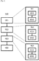
- a first aspect of the invention illustrated in figure 1 relates to a method 100 of determining a preferential minimum power setpoint by a consumer i, said consumer comprising an electric water heater.
- the hot water from the water heater can in particular be used for sanitary facilities, for air conditioning and / or heating.
- the method therefore aims to determine (for possibly supply it to a management system) a set value to be observed for proper management of the water heater of a given consumer i.
- the method 100 comprises, a step 1E1 of determining the state of the consumer i at the instant k.
- the status of a consumer can include the power consumed by the water heater P (i, k). It can also include the number of people Per (i, k) associated with consumer i at time k. Indeed, each consumer i can correspond to a household or more generally to a building, that is to say to one or more people. Of course, the power consumed by the water heater P (i, k) of the consumer i will therefore depend on the number of people Per (i, k) present at each instant k.
- step 1E1 of determining the state of the consumer i at the instant k comprises a substep 1E11 of acquiring the power P (i, k) consumed by the water heater of the consumer i to l 'instant k. This acquisition can for example be done using a communicating counter. At the end of this sub-step 1E11, the power P (i, k) consumed by the water heater of consumer i at time k is known.
- step 1E1 of determining the state of consumer i also includes a sub-step 1E12 of determining the number of people Per (i, k) at time k associated with consumer i.
- the number of people associated with consumer i can for example be determined by measuring the quantity of CO 2 . We can also determine this number from geolocation data obtained using a smartphone (or smartphone). We can also use other information, for example working hours in the case of a company or else a combination of said information.
- the number of people Per (i, k) associated with the consumer i at the instant k is known.
- step 1E1 of determining the state of consumer i at time k we know the number of people Per (i, k) as well as the power consumed P (i, k) by the heater -water at time k associated with said consumer i.
- the method 100 further comprises a step 1E2 of determining a minimum power setpoint P vs min i k at time k as a function of the state of consumer i determined during step 1E1 of determining the state of consumer i at time k.
- step 1E2 of determining a minimum power setpoint P vs min i k at time k includes a sub-step 1E21 for determining the minimum quantity of hot water Min water (i, k) necessary at time k as a function of the number of people Per (i, k) associated with consumer i .
- the quantity of hot water Min water (i, k) associated with the consumer i is determined by taking into account the preferences of each person present.
- Step 1E2 of determining the minimum power setpoint P vs min i k at time k also includes a sub-step 1E22 for determining a minimum power setpoint P vs min i k at time k as a function of the minimum quantity of hot water Min water (i, k) required at time k determined in the preceding sub-step 1E21.
- the factor for converting electrical power to thermal power R ( i ) and / or the thermal dispersion factor between the tank and the ambient temperature Loss factor ( i ) can be determined from measurements and / or supplied by the manufacturer of the water heater.
- the value of this temperature may be chosen to be equal to a predetermined value, for example 15 ° C in summer and 12 ° C in winter.
- the value of this temperature can be chosen to be equal to a predetermined value, for example equal to 22 ° C.
- the method 100 then comprises a step 1E3 of determining a minimum power setpoint P vs min i , k + 1 : K at times k + 1 to K.
- step 1E3 of determining a minimum power setpoint P vs min i , k + 1 : K at times k + 1 to K includes a sub-step 1E31 of determining the quantity of forecast hot water Prev water (i, k + 1: K) consumed at times k + 1 to K as a function of the number of people associated with said audit consumer plus one person (i.e. Per (i, k) + 1 if Per (i, k) + 1 ⁇ N i or N i otherwise) at times k + 1 to K, denoted Per +1 (i, k + 1: K) below.
- the temperature T (i, k) of the hot water is also taken into account during the sub-step of determining the forecast quantity of hot water Prev (i, k + 1: K ) at times k + 1 to K.
- Water prev i , 3 : 5 Water prev i 3 , Water prev i 4 , Water prev i 5 .
- the sub-step 1E31 of determining the quantity of forecast hot water Prev (i, k + 1: K) water consumed at times k + 1 to K comprises a phase for determining an hour d 'arrival of the additional person, the quantity of hot water forecast Water prev (i, k + 1: K) then being determined according to said arrival time.
- the estimated arrival time can be determined by a learning method, based on the actual arrival times previously recorded. Alternatively or additionally, the estimated time of arrival can be determined according to working hours or any other information concerning the timetable of the person or persons associated with the consumer i considered. Alternatively or additionally, the estimated time of arrival can be determined using geolocation information concerning the people associated with the consumer i considered.
- step 1E3 of determining a minimum power setpoint P vs min i , k + 1 : K at times k + 1 to K also includes a sub-step 1E32 for determining the minimum power setpoint P vs min i , k + 1 : K at instants k + 1 to K as a function of the forecast quantity of hot water Prev water (i, k + 1: K) consumed at instants k + 1 to K determined during the preceding sub-step 1E31.
- the temperature T water ( i , k ' + 1) is calculated iteratively from T water ( i, k' ) .
- the method according to a first aspect of the invention also includes a step 1E4 of determining the preferred minimum power setpoint P vs min_pref i k depending on the minimum power setpoint P vs min i k at time k and the minimum power setpoint P vs min i , k + 1 : K at times k + 1 to K.
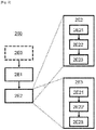
- a second aspect of the invention illustrated in figure 2 relates to a method 200 for controlling a plurality of water heaters on a network comprising a plurality of consumers i, each consumer i of the plurality of consumers i comprising a water heater of the plurality of water heaters.
- the method aims to control the water heaters so as to optimize the consumption of electrical energy, for example to take into account the presence of an intermittent source of electrical energy such as photovoltaic panels or a wind turbine. More particularly, the method aims to determine, for each consumer i, an optimal power setpoint at the instant k denoted P c (i, k).
- the method 200 comprises a step 2E1 of receiving, from each consumer i of the plurality of consumers i, a preferential minimum power setpoint P vs min_pref i k .
- Other data may possibly be received during this step, for example data concerning the state of each consumer i .
- the method according to a second aspect of the invention comprises, before step 2E1 of reception, for each consumer i of the plurality of consumers i, a step 2E0 of implementing a method 100 according to a first aspect of the invention, so as to obtain, for each consumer i, a preferred minimum power setpoint P vs min_pref i k .
- consumers can send the preferential minimum power setpoints to a control system, the latter then being received during step 2E1 of reception.
- Other data may possibly be transmitted to the control system during this step, for example data relating to the state of each consumer i .
- Such communication can, for example, use PLC (for on-line carrier currents) or else wireless communication means.
- PLC for on-line carrier currents
- These preferential minimum power setpoints P vs min_pref i k can then be used to determine optimized instructions (for example to encourage the use of locally produced electrical energy) for each consumer i.
- the method according to a second aspect of the invention comprises, for each consumer i of the plurality of consumers i, a step 2E2 of determining a power setpoint P c (i, k) at time k in function of the preferred minimum power setpoint P vs min_pref i k .
- step 2E2 of determining a power setpoint P c (i, k) at time k comprises a sub-step 2E21 of determining the optimal electrical modulation at time k.
- the optimal electrical modulation is the modulation making it possible to maximize self-consumption or network service. More generally, the optimal electrical modulation is a function of the objectives set for the control process. The determination of an optimal electrical modulation is known to a person skilled in the art and will therefore not be detailed here. The interested reader could for example refer to the problem known as "backpack" or " Knapsack problem " in English, and in particular to the document "A dynamic programming method with lists for the knapsack sharing problem", V. Boyer, D. El Baz, M.
- step 2E2 of determining a power setpoint P c (i, k) at time k comprises a sub-step 2E22 of determining an optimal power setpoint P vs opt i k corresponding to the distribution of the modulation among each consumer i, said distribution being carried out in proportion to the preferred minimum setpoints.
- the Mod (k) modulation may be advantageous not to distribute the Mod (k) modulation proportionally to the preferential minimum setpoints, but rather so as to take into account the satisfaction of each consumer i at the instant k, denoted S (i, k ), said satisfaction S (i, k) being for example equal to 1 when satisfaction is maximum and to 0 when the latter is minimum.
- the satisfaction S (i, k) is a function of the quantity of hot water and / or the number of people and / or the temperature of the hot water in the tank.
- T opt ( i, k ) is an optimal hot water temperature associated with consumer i at time k.
- the latter can for example be chosen by the person or persons associated with said consumer i .
- the latter can be chosen to be equal to a predefined value, for example 55 ° C.
- the distribution is then obtained by determining, for each consumer i , the optimal power P vs opt i k maximizing service satisfaction and power distribution efficiency, i.e. maximizing the following relationship: ⁇ S i k ⁇ not i k
- maximization is done by ensuring that inequality P i k ⁇ P vs min_pref i k is respected for each consumer i.
- each consumer i is associated with an optimal setpoint power P vs opt i k at the instant k making it possible to optimize the satisfaction of the latter.
- step 2E2 of determining a power setpoint P c (i, k) at time k comprises a sub-step 2E23 of determining the power setpoint P c (i, k) , said power setpoint P c (i, k) at time k being the maximum between the optimal power setpoint P vs opt i k (which corresponds to the modulation distributed between the different consumers i) and the preferred minimum setpoint P vs min_pref i k . This ensures that the preferential minimum setpoint is always respected.
- a third aspect of the invention relates to a device comprising the means for implementing a method 100 according to a first aspect of the invention.
- the device comprises means for measuring the electrical consumption P (i, k) of a water heater as well as the water temperature T (i, k) of said water heater.
- the device further comprises a calculation means (for example a processor) associated with a memory (for example a RAM memory), said memory being configured to store the instructions as well as the data necessary for the execution of a method 100 according to a first aspect of the invention.
- the device also includes communication means (for example means making it possible to establish a PLC communication) so that said device can exchange data with a remote management system.
- a fourth aspect of the invention relates to a control system comprising the means for implementing a method 200 according to a second aspect of the invention.
- the device comprises means computation (for example a processor) associated with a memory (for example a RAM memory), said memory being configured to store the instructions as well as the data necessary for the execution of a method 200 according to a second aspect of the invention .
- the device also includes communication means (for example means making it possible to establish a PLC communication) so that said system can exchange data with one or more remote devices, each remote device corresponding to a consumer. .
Landscapes
- Engineering & Computer Science (AREA)
- Physics & Mathematics (AREA)
- Thermal Sciences (AREA)
- General Engineering & Computer Science (AREA)
- Mechanical Engineering (AREA)
- Combustion & Propulsion (AREA)
- Chemical & Material Sciences (AREA)
- Sustainable Energy (AREA)
- Sustainable Development (AREA)
- Life Sciences & Earth Sciences (AREA)
- Automation & Control Theory (AREA)
- General Physics & Mathematics (AREA)
- Management, Administration, Business Operations System, And Electronic Commerce (AREA)
- Heat-Pump Type And Storage Water Heaters (AREA)
Applications Claiming Priority (1)
| Application Number | Priority Date | Filing Date | Title |
|---|---|---|---|
| FR1873783A FR3090829B1 (fr) | 2018-12-21 | 2018-12-21 | Procédé de détermination d’une consigne minimale préférentielle de puissance, Procédé de pilotage d’une pluralité de chauffe-eaux et dispositif associé |
Publications (2)
| Publication Number | Publication Date |
|---|---|
| EP3671399A1 true EP3671399A1 (de) | 2020-06-24 |
| EP3671399B1 EP3671399B1 (de) | 2022-01-05 |
Family
ID=68072455
Family Applications (1)
| Application Number | Title | Priority Date | Filing Date |
|---|---|---|---|
| EP19218815.9A Active EP3671399B1 (de) | 2018-12-21 | 2019-12-20 | Bestimmungsverfahren eines bevorzugten minimalen leistungssollwerts, steuerungsverfahren einer vielzahl von wasserboilern und entsprechende vorrichtung |
Country Status (3)
| Country | Link |
|---|---|
| US (1) | US20200200400A1 (de) |
| EP (1) | EP3671399B1 (de) |
| FR (1) | FR3090829B1 (de) |
Cited By (1)
| Publication number | Priority date | Publication date | Assignee | Title |
|---|---|---|---|---|
| CN116592521A (zh) * | 2023-05-08 | 2023-08-15 | 广东万和热能科技有限公司 | 采暖炉的控制方法、装置及采暖炉 |
Citations (4)
| Publication number | Priority date | Publication date | Assignee | Title |
|---|---|---|---|---|
| WO2014051634A1 (en) * | 2012-09-30 | 2014-04-03 | Nest Labs, Inc. | Intelligent controller for an environmental control system |
| WO2014055059A1 (en) * | 2012-10-01 | 2014-04-10 | Nest Labs, Inc. | Radiant heating controls and methods for an environmental control system |
| FR3033394A1 (fr) | 2015-03-04 | 2016-09-09 | Valeo Systemes Thermiques | Circuit de gestion thermique |
| EP3128635A1 (de) * | 2014-03-31 | 2017-02-08 | Tensor Consulting Co. Ltd. | Analysevorrichtung und -verfahren für stromerzeugungssystem |
Family Cites Families (2)
| Publication number | Priority date | Publication date | Assignee | Title |
|---|---|---|---|---|
| CZ301374B6 (cs) * | 2001-05-16 | 2010-02-03 | Uniflair International S. A. | Klimatizacní systém |
| DK1993183T3 (en) * | 2006-02-15 | 2016-05-17 | Mitsubishi Electric Corp | Power supply system stabilization system |
-
2018
- 2018-12-21 FR FR1873783A patent/FR3090829B1/fr not_active Expired - Fee Related
-
2019
- 2019-12-20 EP EP19218815.9A patent/EP3671399B1/de active Active
- 2019-12-20 US US16/722,708 patent/US20200200400A1/en not_active Abandoned
Patent Citations (4)
| Publication number | Priority date | Publication date | Assignee | Title |
|---|---|---|---|---|
| WO2014051634A1 (en) * | 2012-09-30 | 2014-04-03 | Nest Labs, Inc. | Intelligent controller for an environmental control system |
| WO2014055059A1 (en) * | 2012-10-01 | 2014-04-10 | Nest Labs, Inc. | Radiant heating controls and methods for an environmental control system |
| EP3128635A1 (de) * | 2014-03-31 | 2017-02-08 | Tensor Consulting Co. Ltd. | Analysevorrichtung und -verfahren für stromerzeugungssystem |
| FR3033394A1 (fr) | 2015-03-04 | 2016-09-09 | Valeo Systemes Thermiques | Circuit de gestion thermique |
Non-Patent Citations (2)
| Title |
|---|
| ELAMARI ET AL.: "Using Electric Water Heaters (EWHs) for Power Balancing and Frequency Control in PV-Diesel Hybrid Mini-GridsK", WORLD ENERGY RENEWABLE CONGRESS, 2011 |
| V. BOYERD. EL BAZM. ELKIHEL: "A dynamic programming method with lists for the knapsack sharing problem", COMPUTERS & INDUSTRIAL ENGINEERING, vol. 61, no. 2, 2011, pages 274 - 278, XP028284520, DOI: 10.1016/j.cie.2010.10.015 |
Cited By (1)
| Publication number | Priority date | Publication date | Assignee | Title |
|---|---|---|---|---|
| CN116592521A (zh) * | 2023-05-08 | 2023-08-15 | 广东万和热能科技有限公司 | 采暖炉的控制方法、装置及采暖炉 |
Also Published As
| Publication number | Publication date |
|---|---|
| FR3090829B1 (fr) | 2022-07-22 |
| EP3671399B1 (de) | 2022-01-05 |
| US20200200400A1 (en) | 2020-06-25 |
| FR3090829A1 (fr) | 2020-06-26 |
Similar Documents
| Publication | Publication Date | Title |
|---|---|---|
| EP3404334B1 (de) | Energiespeicherverfahren und -anlage, die einen wasserboiler umfasst | |
| EP3111154B1 (de) | Vorrichtung zum betreiben wenigstens einer teilvorrichtung zur umformung elektrischer energie und deren speicherung in thermischer form, sowie zugehöriges system und verfahren | |
| EP3117158B1 (de) | Elektro-wassererwärmer mit einstellbarer leistung | |
| EP3065021A1 (de) | Warmwasserheizsystem mit dedizierter fotovoltaikanlage | |
| EP3840158B1 (de) | Verfahren zur entlastung der ausgänge einer stromerzeugungsanlage | |
| WO2015158782A1 (fr) | Système de chauffe-eau à consommation énergétique modulable | |
| FR3029326A1 (fr) | Procede et systeme pour la gestion d’energie | |
| WO2023222401A1 (fr) | Procede de prevision d'une puissance produite par au moins un panneau photovoltaique | |
| EP3671399B1 (de) | Bestimmungsverfahren eines bevorzugten minimalen leistungssollwerts, steuerungsverfahren einer vielzahl von wasserboilern und entsprechende vorrichtung | |
| EP3846095A1 (de) | Automatisches verfahren zur steuerung eines elektrischen stromflusses | |
| EP4193095B1 (de) | Verfahren und anlagen zur bereitstellung von energie, insbesondere wärmeenergie, in mindestens einem gebäude oder dergleichen und zugehöriges system | |
| EP3975103A1 (de) | Verfahren und system zur verwaltung von elektrischen energieressourcen innerhalb eines elektrizitätsverteilungsnetzes | |
| EP3816524B1 (de) | Vorrichtung zur wassererhitzung | |
| FR3008484A1 (fr) | Installation de production energetique comprenant un dispositif de prediction meteorologique, notamment une installation de chauffe-eau solaire comprenant un tel dispositif | |
| WO2024008753A1 (fr) | Procédé et installation pour fournir de l'énergie notamment thermique, peu carbonée, dans au moins un bâtiment ou analogue, et système s'y rapportant. | |
| FR3104843A1 (fr) | Micro-réseau à équilibre perfectionné entre consommation et production | |
| EP2936423A1 (de) | Verwaltung von hochtemperaturbatterien | |
| FR2979451A1 (fr) | Procede de determination de la part de la consommation electrique liee aux temperatures exterieures | |
| EP3258187B1 (de) | Verfahren zur änderung des energieverbrauchs eines geräts | |
| EP4066340B1 (de) | Robustes mikronetzwerk für elektrische strahlungsheizgeräte | |
| EP4579572A1 (de) | Verfahren und vorrichtung zur energieverwaltung in einer komplexen umgebung einer wohnung | |
| EP4572073A1 (de) | Verfahren und vorrichtung zur verwaltung der von mindestens einem photovoltaischen paneel erzeugten elektrischen energie | |
| WO2024089194A1 (fr) | Procédé d'estimation d'un indicateur collectif de réduction de consommation énergétique pour un ensemble de dispositifs thermiques, dispositif électronique d'estimation et produit programme d'ordinateur associés | |
| FR3049097A1 (fr) | Procede de gestion de la consommation energetique d’une installation thermique comprenant au moins un dispositif de stockage de chaleur | |
| WO2021186126A1 (fr) | Procede et dispositif de commande d'une station d'alimentation electrique, programme d'ordinateur correspondant et installation d'alimentation electrique |
Legal Events
| Date | Code | Title | Description |
|---|---|---|---|
| PUAI | Public reference made under article 153(3) epc to a published international application that has entered the european phase |
Free format text: ORIGINAL CODE: 0009012 |
|
| STAA | Information on the status of an ep patent application or granted ep patent |
Free format text: STATUS: REQUEST FOR EXAMINATION WAS MADE |
|
| 17P | Request for examination filed |
Effective date: 20191220 |
|
| AK | Designated contracting states |
Kind code of ref document: A1 Designated state(s): AL AT BE BG CH CY CZ DE DK EE ES FI FR GB GR HR HU IE IS IT LI LT LU LV MC MK MT NL NO PL PT RO RS SE SI SK SM TR |
|
| AX | Request for extension of the european patent |
Extension state: BA ME |
|
| RBV | Designated contracting states (corrected) |
Designated state(s): AL AT BE BG CH CY CZ DE DK EE ES FI FR GB GR HR HU IE IS IT LI LT LU LV MC MK MT NL NO PL PT RO RS SE SI SK SM TR |
|
| GRAP | Despatch of communication of intention to grant a patent |
Free format text: ORIGINAL CODE: EPIDOSNIGR1 |
|
| STAA | Information on the status of an ep patent application or granted ep patent |
Free format text: STATUS: GRANT OF PATENT IS INTENDED |
|
| INTG | Intention to grant announced |
Effective date: 20210215 |
|
| GRAJ | Information related to disapproval of communication of intention to grant by the applicant or resumption of examination proceedings by the epo deleted |
Free format text: ORIGINAL CODE: EPIDOSDIGR1 |
|
| STAA | Information on the status of an ep patent application or granted ep patent |
Free format text: STATUS: REQUEST FOR EXAMINATION WAS MADE |
|
| GRAP | Despatch of communication of intention to grant a patent |
Free format text: ORIGINAL CODE: EPIDOSNIGR1 |
|
| STAA | Information on the status of an ep patent application or granted ep patent |
Free format text: STATUS: GRANT OF PATENT IS INTENDED |
|
| INTC | Intention to grant announced (deleted) | ||
| INTG | Intention to grant announced |
Effective date: 20210714 |
|
| GRAS | Grant fee paid |
Free format text: ORIGINAL CODE: EPIDOSNIGR3 |
|
| GRAA | (expected) grant |
Free format text: ORIGINAL CODE: 0009210 |
|
| STAA | Information on the status of an ep patent application or granted ep patent |
Free format text: STATUS: THE PATENT HAS BEEN GRANTED |
|
| AK | Designated contracting states |
Kind code of ref document: B1 Designated state(s): AL AT BE BG CH CY CZ DE DK EE ES FI FR GB GR HR HU IE IS IT LI LT LU LV MC MK MT NL NO PL PT RO RS SE SI SK SM TR |
|
| REG | Reference to a national code |
Ref country code: GB Ref legal event code: FG4D Free format text: NOT ENGLISH |
|
| REG | Reference to a national code |
Ref country code: CH Ref legal event code: EP |
|
| REG | Reference to a national code |
Ref country code: AT Ref legal event code: REF Ref document number: 1461151 Country of ref document: AT Kind code of ref document: T Effective date: 20220115 |
|
| REG | Reference to a national code |
Ref country code: DE Ref legal event code: R096 Ref document number: 602019010669 Country of ref document: DE |
|
| REG | Reference to a national code |
Ref country code: IE Ref legal event code: FG4D Free format text: LANGUAGE OF EP DOCUMENT: FRENCH |
|
| REG | Reference to a national code |
Ref country code: LT Ref legal event code: MG9D |
|
| REG | Reference to a national code |
Ref country code: NL Ref legal event code: MP Effective date: 20220105 |
|
| REG | Reference to a national code |
Ref country code: AT Ref legal event code: MK05 Ref document number: 1461151 Country of ref document: AT Kind code of ref document: T Effective date: 20220105 |
|
| PG25 | Lapsed in a contracting state [announced via postgrant information from national office to epo] |
Ref country code: NL Free format text: LAPSE BECAUSE OF FAILURE TO SUBMIT A TRANSLATION OF THE DESCRIPTION OR TO PAY THE FEE WITHIN THE PRESCRIBED TIME-LIMIT Effective date: 20220105 |
|
| PG25 | Lapsed in a contracting state [announced via postgrant information from national office to epo] |
Ref country code: SE Free format text: LAPSE BECAUSE OF FAILURE TO SUBMIT A TRANSLATION OF THE DESCRIPTION OR TO PAY THE FEE WITHIN THE PRESCRIBED TIME-LIMIT Effective date: 20220105 Ref country code: RS Free format text: LAPSE BECAUSE OF FAILURE TO SUBMIT A TRANSLATION OF THE DESCRIPTION OR TO PAY THE FEE WITHIN THE PRESCRIBED TIME-LIMIT Effective date: 20220105 Ref country code: PT Free format text: LAPSE BECAUSE OF FAILURE TO SUBMIT A TRANSLATION OF THE DESCRIPTION OR TO PAY THE FEE WITHIN THE PRESCRIBED TIME-LIMIT Effective date: 20220505 Ref country code: NO Free format text: LAPSE BECAUSE OF FAILURE TO SUBMIT A TRANSLATION OF THE DESCRIPTION OR TO PAY THE FEE WITHIN THE PRESCRIBED TIME-LIMIT Effective date: 20220405 Ref country code: LT Free format text: LAPSE BECAUSE OF FAILURE TO SUBMIT A TRANSLATION OF THE DESCRIPTION OR TO PAY THE FEE WITHIN THE PRESCRIBED TIME-LIMIT Effective date: 20220105 Ref country code: HR Free format text: LAPSE BECAUSE OF FAILURE TO SUBMIT A TRANSLATION OF THE DESCRIPTION OR TO PAY THE FEE WITHIN THE PRESCRIBED TIME-LIMIT Effective date: 20220105 Ref country code: ES Free format text: LAPSE BECAUSE OF FAILURE TO SUBMIT A TRANSLATION OF THE DESCRIPTION OR TO PAY THE FEE WITHIN THE PRESCRIBED TIME-LIMIT Effective date: 20220105 Ref country code: BG Free format text: LAPSE BECAUSE OF FAILURE TO SUBMIT A TRANSLATION OF THE DESCRIPTION OR TO PAY THE FEE WITHIN THE PRESCRIBED TIME-LIMIT Effective date: 20220405 |
|
| PG25 | Lapsed in a contracting state [announced via postgrant information from national office to epo] |
Ref country code: PL Free format text: LAPSE BECAUSE OF FAILURE TO SUBMIT A TRANSLATION OF THE DESCRIPTION OR TO PAY THE FEE WITHIN THE PRESCRIBED TIME-LIMIT Effective date: 20220105 Ref country code: LV Free format text: LAPSE BECAUSE OF FAILURE TO SUBMIT A TRANSLATION OF THE DESCRIPTION OR TO PAY THE FEE WITHIN THE PRESCRIBED TIME-LIMIT Effective date: 20220105 Ref country code: GR Free format text: LAPSE BECAUSE OF FAILURE TO SUBMIT A TRANSLATION OF THE DESCRIPTION OR TO PAY THE FEE WITHIN THE PRESCRIBED TIME-LIMIT Effective date: 20220406 Ref country code: FI Free format text: LAPSE BECAUSE OF FAILURE TO SUBMIT A TRANSLATION OF THE DESCRIPTION OR TO PAY THE FEE WITHIN THE PRESCRIBED TIME-LIMIT Effective date: 20220105 Ref country code: AT Free format text: LAPSE BECAUSE OF FAILURE TO SUBMIT A TRANSLATION OF THE DESCRIPTION OR TO PAY THE FEE WITHIN THE PRESCRIBED TIME-LIMIT Effective date: 20220105 |
|
| PG25 | Lapsed in a contracting state [announced via postgrant information from national office to epo] |
Ref country code: IS Free format text: LAPSE BECAUSE OF FAILURE TO SUBMIT A TRANSLATION OF THE DESCRIPTION OR TO PAY THE FEE WITHIN THE PRESCRIBED TIME-LIMIT Effective date: 20220505 |
|
| REG | Reference to a national code |
Ref country code: DE Ref legal event code: R097 Ref document number: 602019010669 Country of ref document: DE |
|
| PG25 | Lapsed in a contracting state [announced via postgrant information from national office to epo] |
Ref country code: SM Free format text: LAPSE BECAUSE OF FAILURE TO SUBMIT A TRANSLATION OF THE DESCRIPTION OR TO PAY THE FEE WITHIN THE PRESCRIBED TIME-LIMIT Effective date: 20220105 Ref country code: SK Free format text: LAPSE BECAUSE OF FAILURE TO SUBMIT A TRANSLATION OF THE DESCRIPTION OR TO PAY THE FEE WITHIN THE PRESCRIBED TIME-LIMIT Effective date: 20220105 Ref country code: RO Free format text: LAPSE BECAUSE OF FAILURE TO SUBMIT A TRANSLATION OF THE DESCRIPTION OR TO PAY THE FEE WITHIN THE PRESCRIBED TIME-LIMIT Effective date: 20220105 Ref country code: EE Free format text: LAPSE BECAUSE OF FAILURE TO SUBMIT A TRANSLATION OF THE DESCRIPTION OR TO PAY THE FEE WITHIN THE PRESCRIBED TIME-LIMIT Effective date: 20220105 Ref country code: DK Free format text: LAPSE BECAUSE OF FAILURE TO SUBMIT A TRANSLATION OF THE DESCRIPTION OR TO PAY THE FEE WITHIN THE PRESCRIBED TIME-LIMIT Effective date: 20220105 Ref country code: CZ Free format text: LAPSE BECAUSE OF FAILURE TO SUBMIT A TRANSLATION OF THE DESCRIPTION OR TO PAY THE FEE WITHIN THE PRESCRIBED TIME-LIMIT Effective date: 20220105 |
|
| PLBE | No opposition filed within time limit |
Free format text: ORIGINAL CODE: 0009261 |
|
| STAA | Information on the status of an ep patent application or granted ep patent |
Free format text: STATUS: NO OPPOSITION FILED WITHIN TIME LIMIT |
|
| PG25 | Lapsed in a contracting state [announced via postgrant information from national office to epo] |
Ref country code: AL Free format text: LAPSE BECAUSE OF FAILURE TO SUBMIT A TRANSLATION OF THE DESCRIPTION OR TO PAY THE FEE WITHIN THE PRESCRIBED TIME-LIMIT Effective date: 20220105 |
|
| 26N | No opposition filed |
Effective date: 20221006 |
|
| PG25 | Lapsed in a contracting state [announced via postgrant information from national office to epo] |
Ref country code: SI Free format text: LAPSE BECAUSE OF FAILURE TO SUBMIT A TRANSLATION OF THE DESCRIPTION OR TO PAY THE FEE WITHIN THE PRESCRIBED TIME-LIMIT Effective date: 20220105 |
|
| PG25 | Lapsed in a contracting state [announced via postgrant information from national office to epo] |
Ref country code: IT Free format text: LAPSE BECAUSE OF FAILURE TO SUBMIT A TRANSLATION OF THE DESCRIPTION OR TO PAY THE FEE WITHIN THE PRESCRIBED TIME-LIMIT Effective date: 20220105 |
|
| REG | Reference to a national code |
Ref country code: CH Ref legal event code: PL |
|
| REG | Reference to a national code |
Ref country code: BE Ref legal event code: MM Effective date: 20221231 |
|
| PG25 | Lapsed in a contracting state [announced via postgrant information from national office to epo] |
Ref country code: LU Free format text: LAPSE BECAUSE OF NON-PAYMENT OF DUE FEES Effective date: 20221220 |
|
| PG25 | Lapsed in a contracting state [announced via postgrant information from national office to epo] |
Ref country code: LI Free format text: LAPSE BECAUSE OF NON-PAYMENT OF DUE FEES Effective date: 20221231 Ref country code: IE Free format text: LAPSE BECAUSE OF NON-PAYMENT OF DUE FEES Effective date: 20221220 Ref country code: CH Free format text: LAPSE BECAUSE OF NON-PAYMENT OF DUE FEES Effective date: 20221231 |
|
| PG25 | Lapsed in a contracting state [announced via postgrant information from national office to epo] |
Ref country code: BE Free format text: LAPSE BECAUSE OF NON-PAYMENT OF DUE FEES Effective date: 20221231 |
|
| PG25 | Lapsed in a contracting state [announced via postgrant information from national office to epo] |
Ref country code: HU Free format text: LAPSE BECAUSE OF FAILURE TO SUBMIT A TRANSLATION OF THE DESCRIPTION OR TO PAY THE FEE WITHIN THE PRESCRIBED TIME-LIMIT; INVALID AB INITIO Effective date: 20191220 |
|
| PG25 | Lapsed in a contracting state [announced via postgrant information from national office to epo] |
Ref country code: CY Free format text: LAPSE BECAUSE OF FAILURE TO SUBMIT A TRANSLATION OF THE DESCRIPTION OR TO PAY THE FEE WITHIN THE PRESCRIBED TIME-LIMIT Effective date: 20220105 |
|
| PG25 | Lapsed in a contracting state [announced via postgrant information from national office to epo] |
Ref country code: MK Free format text: LAPSE BECAUSE OF FAILURE TO SUBMIT A TRANSLATION OF THE DESCRIPTION OR TO PAY THE FEE WITHIN THE PRESCRIBED TIME-LIMIT Effective date: 20220105 |
|
| PG25 | Lapsed in a contracting state [announced via postgrant information from national office to epo] |
Ref country code: MC Free format text: LAPSE BECAUSE OF FAILURE TO SUBMIT A TRANSLATION OF THE DESCRIPTION OR TO PAY THE FEE WITHIN THE PRESCRIBED TIME-LIMIT Effective date: 20220105 |
|
| PG25 | Lapsed in a contracting state [announced via postgrant information from national office to epo] |
Ref country code: TR Free format text: LAPSE BECAUSE OF FAILURE TO SUBMIT A TRANSLATION OF THE DESCRIPTION OR TO PAY THE FEE WITHIN THE PRESCRIBED TIME-LIMIT Effective date: 20220105 Ref country code: MC Free format text: LAPSE BECAUSE OF FAILURE TO SUBMIT A TRANSLATION OF THE DESCRIPTION OR TO PAY THE FEE WITHIN THE PRESCRIBED TIME-LIMIT Effective date: 20220105 |
|
| GBPC | Gb: european patent ceased through non-payment of renewal fee |
Effective date: 20231220 |
|
| PG25 | Lapsed in a contracting state [announced via postgrant information from national office to epo] |
Ref country code: MT Free format text: LAPSE BECAUSE OF FAILURE TO SUBMIT A TRANSLATION OF THE DESCRIPTION OR TO PAY THE FEE WITHIN THE PRESCRIBED TIME-LIMIT Effective date: 20220105 |
|
| PG25 | Lapsed in a contracting state [announced via postgrant information from national office to epo] |
Ref country code: GB Free format text: LAPSE BECAUSE OF NON-PAYMENT OF DUE FEES Effective date: 20231220 |
|
| PG25 | Lapsed in a contracting state [announced via postgrant information from national office to epo] |
Ref country code: GB Free format text: LAPSE BECAUSE OF NON-PAYMENT OF DUE FEES Effective date: 20231220 |
|
| PGFP | Annual fee paid to national office [announced via postgrant information from national office to epo] |
Ref country code: FR Payment date: 20241227 Year of fee payment: 6 |
|
| PGFP | Annual fee paid to national office [announced via postgrant information from national office to epo] |
Ref country code: DE Payment date: 20241219 Year of fee payment: 6 |