EP4572073A1 - Verfahren und vorrichtung zur verwaltung der von mindestens einem photovoltaischen paneel erzeugten elektrischen energie - Google Patents
Verfahren und vorrichtung zur verwaltung der von mindestens einem photovoltaischen paneel erzeugten elektrischen energie Download PDFInfo
- Publication number
- EP4572073A1 EP4572073A1 EP24218812.6A EP24218812A EP4572073A1 EP 4572073 A1 EP4572073 A1 EP 4572073A1 EP 24218812 A EP24218812 A EP 24218812A EP 4572073 A1 EP4572073 A1 EP 4572073A1
- Authority
- EP
- European Patent Office
- Prior art keywords
- electrical energy
- network
- photovoltaic panel
- controller
- switch
- Prior art date
- Legal status (The legal status is an assumption and is not a legal conclusion. Google has not performed a legal analysis and makes no representation as to the accuracy of the status listed.)
- Pending
Links
Images

Classifications
-
- H—ELECTRICITY
- H02—GENERATION; CONVERSION OR DISTRIBUTION OF ELECTRIC POWER
- H02J—ELECTRIC POWER NETWORKS; CIRCUIT ARRANGEMENTS OR SYSTEMS FOR SUPPLYING OR DISTRIBUTING ELECTRIC POWER; SYSTEMS FOR STORING ELECTRIC ENERGY
- H02J3/00—Circuit arrangements for AC mains or AC distribution networks
- H02J3/38—Arrangements for feeding a single network from two or more generators or sources in parallel; Arrangements for feeding already energised networks from additional generators or sources in parallel
- H02J3/381—Dispersed generators
-
- G—PHYSICS
- G06—COMPUTING OR CALCULATING; COUNTING
- G06Q—INFORMATION AND COMMUNICATION TECHNOLOGY [ICT] SPECIALLY ADAPTED FOR ADMINISTRATIVE, COMMERCIAL, FINANCIAL, MANAGERIAL OR SUPERVISORY PURPOSES; SYSTEMS OR METHODS SPECIALLY ADAPTED FOR ADMINISTRATIVE, COMMERCIAL, FINANCIAL, MANAGERIAL OR SUPERVISORY PURPOSES, NOT OTHERWISE PROVIDED FOR
- G06Q50/00—Information and communication technology [ICT] specially adapted for implementation of business processes of specific business sectors, e.g. utilities or tourism
- G06Q50/06—Energy or water supply
-
- H—ELECTRICITY
- H02—GENERATION; CONVERSION OR DISTRIBUTION OF ELECTRIC POWER
- H02J—ELECTRIC POWER NETWORKS; CIRCUIT ARRANGEMENTS OR SYSTEMS FOR SUPPLYING OR DISTRIBUTING ELECTRIC POWER; SYSTEMS FOR STORING ELECTRIC ENERGY
- H02J2101/00—Supply or distribution of decentralised, dispersed or local electric power generation
- H02J2101/20—Dispersed power generation using renewable energy sources
- H02J2101/22—Solar energy
- H02J2101/24—Photovoltaics
-
- H—ELECTRICITY
- H02—GENERATION; CONVERSION OR DISTRIBUTION OF ELECTRIC POWER
- H02J—ELECTRIC POWER NETWORKS; CIRCUIT ARRANGEMENTS OR SYSTEMS FOR SUPPLYING OR DISTRIBUTING ELECTRIC POWER; SYSTEMS FOR STORING ELECTRIC ENERGY
- H02J2105/00—Networks for supplying or distributing electric power characterised by their spatial reach or by the load
- H02J2105/10—Local stationary networks having a local or delimited stationary reach
- H02J2105/12—Local stationary networks having a local or delimited stationary reach supplying households or buildings
Definitions
- the present invention relates to a method and a device for managing the electrical energy produced by at least one photovoltaic panel.
- Electricity production from carbon products varies depending on the time of day (for example, it is more carbon-intensive at 7 p.m. than at 3 a.m.), the day of the week (it is less carbon-intensive on weekends), and the season (it is more carbon-intensive in winter).
- photovoltaic panels The electrical energy provided by photovoltaic panels is directly linked to sunshine; it is sometimes difficult to ensure complete autonomy in electrical energy for a building with photovoltaic panels.
- the management device makes it possible to distribute energy in an optimized manner between the energy supply network and the electrical energy consuming device.
- the method further comprises the step of control by the controller of the switch so that the electrical energy supplied by the at least one photovoltaic panel is delivered to the electrical energy supply network if the capability of the network is less than a first predetermined threshold and in that the control by the controller of the switch so that the electrical energy supplied by the at least one photovoltaic panel is delivered to the electrical energy consuming device during a given period as a function of the information representative of the capability of the network is immediate or is carried out during a predetermined time interval.
- the method makes it possible to increase the consistency of the commands in relation to the state of the electrical energy supply network, in order, for example, not to increase the load on the electrical energy supply network in order to promote self-consumption of energy supplied by at least one photovoltaic panel at an inopportune time with regard to the state of the electrical energy supply network.
- the time interval is between 1 hour and 24 hours or between one day and one week.
- This interval therefore ensures optimal charging in light of the network capacity and the uses of the electrical energy consuming device, as well as the horizon of the data required for decision-making.
- the control of the switch so that the electrical energy supplied by the at least one photovoltaic panel is delivered to the electrical energy consuming device during the given period as a function of the information representative of the capability of the network is carried out by comparing a ratio between an electrical power delivered by the network Res divided by an operating power of the electrical energy consuming device with the ratio between the network capacity at a first instant divided by the network capacity at a second instant within the predetermined time interval.
- this embodiment makes it possible to compare two instants for which the characteristics of the network are different by also integrating the production characteristics of at least one photovoltaic panel.
- the network capability is determined from different tariffs for an electrical consumption of network energy.
- this embodiment makes it possible to obtain information representative of the load of the electrical energy supply network without using a server.
- a computer program which can be stored on a medium and/or downloaded from a communication network, in order to be read by a processor.
- This computer program comprises instructions for implementing the method performed by an internet gateway, as mentioned above, when said program is executed by the processor.
- the invention also relates to an information storage medium storing such a computer program.
- FIG. 1 represents an example of architecture of an electrical energy supply system for a building in which the present invention is implemented.
- the Bat building includes at least one PV photovoltaic panel, a Conv converter, a Sen power sensor delivered by the PV photovoltaic panel, a Com switch, a Cont controller and a Cmp smart electricity meter.
- the Conv converter converts the direct electrical energy delivered by at least one photovoltaic panel into a 230V alternating signal identical to the alternating signal delivered by a Res electrical energy supply network.
- the alternating signal delivered by the Res electricity supply network is delivered to the Cmp smart meter to be retransmitted to the Com switch.
- the Cmp smart meter for example, is connected to the Cont controller to provide pricing information such as off-peak or peak pricing.
- pricing information is entered by the building occupant or obtained from a remote server.
- the Com switch is controlled by the Cont controller.
- the Cont controller is connected to the Sen electrical power sensor and, for example, to a remote data server Serv.
- the Serv server contains data representative of the electrical energy consumption for all or part of the electrical energy supply network and in particular allows the Cont controller to determine when the production of electricity from carbon products is or will be significant.
- the COM switch is connected to a DHW device that consumes electrical energy.
- the DHW device is, for example, a hot water tank.
- the hot water tank stores energy for later use.
- the ECS device is, for example, air conditioning or ventilation equipment, cycle household appliances (washing machines, etc.) or an electric vehicle.
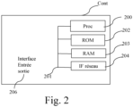
- FIG. 2 schematically illustrates an exemplary hardware arrangement of a controller according to the present invention.
- the Cont controller comprises, connected by a communication bus 201: a processor Proc 200; a RAM (Random Access Memory) 203; a ROM (Read Only Memory) 202 or a Flash memory and a network interface 204.
- the Proc 200 processor is capable of executing instructions loaded into the RAM memory 203 from the ROM memory 202, an external memory (such as an SD card), a storage medium (such as the HDD hard disk), or a communication network.
- the Proc 200 processor is capable of reading instructions from the RAM memory 203 and executing them.
- These instructions form a computer program causing the Proc 200 processor to implement all or part of the behaviors, algorithms and steps described herein.
- all or part of the algorithms and steps described herein may be implemented in software form by executing a set of instructions by a programmable machine, such as a DSP (Digital Signal Processor) or a microcontroller or a processor.
- a programmable machine such as a DSP (Digital Signal Processor) or a microcontroller or a processor.
- Cont controller comprises electronic circuitry adapted and configured to implement the behaviors, algorithms and steps described herein.
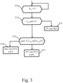
- FIG. 3 illustrates a first example of an algorithm for managing the electrical energy supplied by at least one photovoltaic panel.
- the algorithm is executed by the Cont controller.
- the controller Cont obtains a measurement of the power delivered by at least one PV photovoltaic panel and checks whether it is non-zero.
- the controller Cont obtains from the server Serv a value of the network capability C Res .
- the network capability C Res is the proportion of power still available.
- the lower the network capability C Res the higher the carbon content of the energy consumed in the production of electricity.
- the capability obtained at this step is denoted C Res (t0).
- the parameter C Res corresponds to the network capacity, i.e. the percentage of available power P_network still available compared to a maximum power P MAX which can be defined according to the criteria to be favored (maximum power of "green” energy available on the territory, maximum power produced on the territory excluding imports, whether international or regional, etc.)
- P MAX is a static parameter which does not depend on time. In reality, this parameter can depend on time; for example when it concerns the maximum power of "green” energy available. This value depends on the irradiance of the day, the meteorology and therefore the time. P MAX can thus be variable depending on time provided that it is possible to have an estimate of this parameter for a time window.
- the Cont controller checks whether the value of the network capability C Res is greater than 0.
- the Cont controller goes to step E33. If not, the Cont controller goes to step E32.
- step E32 the controller Cont controls the switch Com so that the energy produced by the at least one photovoltaic panel is injected into the network Res.
- the controller Cont checks whether I(t0) ⁇ I(t1), with I(t) impact of the load of the ECS device at time t, equivalent to a(t0) ⁇ C Res (t0) / C Res (t1).
- instant t1 is a favorable moment for the load. For example, from the prediction of the total consumption of the territory at instant t1 provided by the server Serv, we can determine the instant t1 where the network capability is maximum. The maximum difference between t1 and t0 depends on the usage.
- the controller Cont controls the switch Com so that the energy supplied by the network is injected into the ECS device at time t1.
- the controller Cont controls the switch Com so that the energy produced by the at least one photovoltaic panel is injected into the ECS device at time t0.
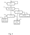
- FIG. 4 illustrates a second example of an algorithm for managing the electrical energy supplied by at least one photovoltaic panel.
- the measurement of network capability by assuming that the pricing of the energy delivered by the Res network or of the energy produced by at least one photovoltaic panel and transferred to the Res network is a function inversely proportional to the capability of the Res network.
- Some photovoltaic equipment cannot provide all the electrical energy required to completely heat a DHW device when it is a hot water tank.
- One way to increase self-consumption is to combine the energy produced by at least one photovoltaic panel with the electrical energy supplied by the Res network. This, however, leads to an increase in the cost of heating the water in the hot water tank.
- the DHW hot water tank is charged with the production of at least one PV photovoltaic panel at the power produced by the PV photovoltaic panel ( ⁇ .P ECS ) and the additional energy is supplied by the network.
- the current rate is HC (Off-peak hours) for energy supplied by the network.
- the DHW tank is charged with PV production at the power produced by the PV photovoltaic panel ( ⁇ .P ECS ).
- the current rate is HP (peak hours) for energy supplied by the network.
- the water in the DHW hot water tank is heated during off-peak tariff periods.
- the energy supplied by the PV photovoltaic panel is resold to the network at the tariff applied at time t.
- the Cont controller checks whether the variable ⁇ is positive.
- step E41 the Cont controller checks whether the off-peak pricing is in effect. If so, the Cont controller moves on to step E44. If not, the Cont controller moves on to step E42.
- the Cont controller checks whether the variable ⁇ is less than a variable ⁇ 0 where ⁇ 0 -(T HP - T HC ) / (T HP - T RESALE ).
- step E46 If yes, the Cont controller goes to step E46. If no, the Cont controller goes to step E43.
- step E42 the controller Cont controls the switch Com so that the energy produced by the at least one photovoltaic panel and the energy delivered by the network Res are injected into the ECS device during peak hours.
- the Cont controller checks whether the off-peak rate is higher than the resale rate for the energy produced by at least one photovoltaic panel.
- step E45 If yes, the Cont controller goes to step E45. If no, the Cont controller goes to step E46.
- step E45 the controller Cont controls the switch Com so that the energy produced by the at least one photovoltaic panel and the energy delivered by the network Res are injected into the ECS device during off-peak hours.
- step E46 the controller Cont controls the switch Com so that the energy produced by the at least one photovoltaic panel is delivered to the Res network and the ECS device is supplied with electrical energy supplied by the Res network during off-peak hours.
Landscapes
- Business, Economics & Management (AREA)
- Engineering & Computer Science (AREA)
- Health & Medical Sciences (AREA)
- Economics (AREA)
- Marketing (AREA)
- Tourism & Hospitality (AREA)
- General Health & Medical Sciences (AREA)
- Human Resources & Organizations (AREA)
- Public Health (AREA)
- Primary Health Care (AREA)
- Strategic Management (AREA)
- Water Supply & Treatment (AREA)
- Physics & Mathematics (AREA)
- General Business, Economics & Management (AREA)
- General Physics & Mathematics (AREA)
- Theoretical Computer Science (AREA)
- Power Engineering (AREA)
- Supply And Distribution Of Alternating Current (AREA)
- Remote Monitoring And Control Of Power-Distribution Networks (AREA)
Applications Claiming Priority (1)
| Application Number | Priority Date | Filing Date | Title |
|---|---|---|---|
| FR2313930A FR3156605A1 (fr) | 2023-12-11 | 2023-12-11 | Procede et dispositif de gestion de l’energie electrique produite par au moins un panneau photovoltaique |
Publications (1)
| Publication Number | Publication Date |
|---|---|
| EP4572073A1 true EP4572073A1 (de) | 2025-06-18 |
Family
ID=91432800
Family Applications (1)
| Application Number | Title | Priority Date | Filing Date |
|---|---|---|---|
| EP24218812.6A Pending EP4572073A1 (de) | 2023-12-11 | 2024-12-10 | Verfahren und vorrichtung zur verwaltung der von mindestens einem photovoltaischen paneel erzeugten elektrischen energie |
Country Status (2)
| Country | Link |
|---|---|
| EP (1) | EP4572073A1 (de) |
| FR (1) | FR3156605A1 (de) |
Citations (5)
| Publication number | Priority date | Publication date | Assignee | Title |
|---|---|---|---|---|
| US20140052310A1 (en) * | 2011-05-30 | 2014-02-20 | Panasonic Corporaton | Power supply system |
| US9671843B2 (en) * | 2011-03-31 | 2017-06-06 | Energent Incorporated | Computer implemented electrical energy hub management system and method |
| US20210003974A1 (en) * | 2019-07-02 | 2021-01-07 | Microsoft Technology Licensing, Llc | Power grid aware machine learning device |
| WO2023030638A1 (en) * | 2021-09-03 | 2023-03-09 | Telefonaktiebolaget Lm Ericsson (Publ) | Intelligent source switching in microgrid connected households |
| US20230387682A1 (en) * | 2020-11-20 | 2023-11-30 | Tokyo Electric Power Company Holdings, Incorporated | Control Method, Management Device, Non-Transitory Computer-Readable Storage Medium and Power System |
-
2023
- 2023-12-11 FR FR2313930A patent/FR3156605A1/fr active Pending
-
2024
- 2024-12-10 EP EP24218812.6A patent/EP4572073A1/de active Pending
Patent Citations (5)
| Publication number | Priority date | Publication date | Assignee | Title |
|---|---|---|---|---|
| US9671843B2 (en) * | 2011-03-31 | 2017-06-06 | Energent Incorporated | Computer implemented electrical energy hub management system and method |
| US20140052310A1 (en) * | 2011-05-30 | 2014-02-20 | Panasonic Corporaton | Power supply system |
| US20210003974A1 (en) * | 2019-07-02 | 2021-01-07 | Microsoft Technology Licensing, Llc | Power grid aware machine learning device |
| US20230387682A1 (en) * | 2020-11-20 | 2023-11-30 | Tokyo Electric Power Company Holdings, Incorporated | Control Method, Management Device, Non-Transitory Computer-Readable Storage Medium and Power System |
| WO2023030638A1 (en) * | 2021-09-03 | 2023-03-09 | Telefonaktiebolaget Lm Ericsson (Publ) | Intelligent source switching in microgrid connected households |
Also Published As
| Publication number | Publication date |
|---|---|
| FR3156605A1 (fr) | 2025-06-13 |
Similar Documents
| Publication | Publication Date | Title |
|---|---|---|
| JP6592454B2 (ja) | 電力制御システム、電力制御方法及びプログラム | |
| US20160241034A1 (en) | Power management system, power management method, and computer program | |
| FR3029326A1 (fr) | Procede et systeme pour la gestion d’energie | |
| EP3840158B1 (de) | Verfahren zur entlastung der ausgänge einer stromerzeugungsanlage | |
| WO2015158782A1 (fr) | Système de chauffe-eau à consommation énergétique modulable | |
| EP2494672A2 (de) | Verwaltung des wiederaufladens eines batteriesets | |
| FR3018594A1 (fr) | Chauffe-eau joule regulable en puissance | |
| EP4572073A1 (de) | Verfahren und vorrichtung zur verwaltung der von mindestens einem photovoltaischen paneel erzeugten elektrischen energie | |
| EP3394923A1 (de) | System und verfahren zur steuerung einer stromspeichervorrichtung | |
| EP3671399B1 (de) | Bestimmungsverfahren eines bevorzugten minimalen leistungssollwerts, steuerungsverfahren einer vielzahl von wasserboilern und entsprechende vorrichtung | |
| FR3104843A1 (fr) | Micro-réseau à équilibre perfectionné entre consommation et production | |
| JP5912055B2 (ja) | 制御装置及び制御方法 | |
| EP4308859B1 (de) | System zur verwaltung einer gleichstromquelle mit variabler leistung | |
| FR3008484A1 (fr) | Installation de production energetique comprenant un dispositif de prediction meteorologique, notamment une installation de chauffe-eau solaire comprenant un tel dispositif | |
| EP4066340B1 (de) | Robustes mikronetzwerk für elektrische strahlungsheizgeräte | |
| EP4597775A1 (de) | Verfahren und vorrichtung zur verwaltung des stromverbrauchs in einem gebäude | |
| EP3816524A1 (de) | Vorrichtung zur wassererhitzung | |
| WO2017174909A1 (fr) | Procede d'optimisation de la consommation electrique d'une installation | |
| JP7427557B2 (ja) | 充電制御装置、充電制御方法、および、充電制御プログラム | |
| EP4686034A1 (de) | Verfahren und vorrichtung zur verwaltung der von einer intelligenten verbrauchsvorrichtung in zusammenhang mit einem energiemanager in einem gebäude verbrauchten elektrischen leistung | |
| EP4603663A1 (de) | System und verfahren zur steuerung eines badebeckens, wie schwimmbecken oder spa | |
| FR3058240B1 (fr) | Procede d'optimisation de la consommation electrique d'une installation | |
| EP4650906A1 (de) | Verfahren zur steuerung eines elektrischen leistungsanrufs | |
| FR3025296A1 (fr) | Gestion de la relance d'un systeme de chauffage thermodynamique | |
| FR3087286A1 (fr) | Optimisation d'un partage d'energie electrique en contexte d'autoconsommation et d'autoproduction collectives |
Legal Events
| Date | Code | Title | Description |
|---|---|---|---|
| PUAI | Public reference made under article 153(3) epc to a published international application that has entered the european phase |
Free format text: ORIGINAL CODE: 0009012 |
|
| STAA | Information on the status of an ep patent application or granted ep patent |
Free format text: STATUS: THE APPLICATION HAS BEEN PUBLISHED |
|
| AK | Designated contracting states |
Kind code of ref document: A1 Designated state(s): AL AT BE BG CH CY CZ DE DK EE ES FI FR GB GR HR HU IE IS IT LI LT LU LV MC ME MK MT NL NO PL PT RO RS SE SI SK SM TR |
|
| STAA | Information on the status of an ep patent application or granted ep patent |
Free format text: STATUS: REQUEST FOR EXAMINATION WAS MADE |
|
| 17P | Request for examination filed |
Effective date: 20251217 |