EP3671035B1 - Light with cooling fins in the light housing - Google Patents
Light with cooling fins in the light housing Download PDFInfo
- Publication number
- EP3671035B1 EP3671035B1 EP19218415.8A EP19218415A EP3671035B1 EP 3671035 B1 EP3671035 B1 EP 3671035B1 EP 19218415 A EP19218415 A EP 19218415A EP 3671035 B1 EP3671035 B1 EP 3671035B1
- Authority
- EP
- European Patent Office
- Prior art keywords
- light
- rib
- fins
- light emission
- rib arrangement
- Prior art date
- Legal status (The legal status is an assumption and is not a legal conclusion. Google has not performed a legal analysis and makes no representation as to the accuracy of the status listed.)
- Active
Links
- 238000001816 cooling Methods 0.000 title description 9
- 230000003287 optical effect Effects 0.000 claims description 10
- 239000004020 conductor Substances 0.000 claims description 5
- 238000000034 method Methods 0.000 claims description 5
- 238000007789 sealing Methods 0.000 claims description 4
- 238000005266 casting Methods 0.000 claims description 3
- 238000005058 metal casting Methods 0.000 claims description 3
- 238000009826 distribution Methods 0.000 description 5
- 230000017525 heat dissipation Effects 0.000 description 5
- 238000004519 manufacturing process Methods 0.000 description 5
- 229910052751 metal Inorganic materials 0.000 description 4
- 239000002184 metal Substances 0.000 description 4
- 239000000463 material Substances 0.000 description 3
- 150000003071 polychlorinated biphenyls Chemical class 0.000 description 2
- 239000000243 solution Substances 0.000 description 2
- 239000004593 Epoxy Substances 0.000 description 1
- 229910052782 aluminium Inorganic materials 0.000 description 1
- XAGFODPZIPBFFR-UHFFFAOYSA-N aluminium Chemical compound [Al] XAGFODPZIPBFFR-UHFFFAOYSA-N 0.000 description 1
- 230000015572 biosynthetic process Effects 0.000 description 1
- 238000005253 cladding Methods 0.000 description 1
- 230000000694 effects Effects 0.000 description 1
- 238000005516 engineering process Methods 0.000 description 1
- 238000001746 injection moulding Methods 0.000 description 1
- 239000011810 insulating material Substances 0.000 description 1
- 238000007639 printing Methods 0.000 description 1
Images


Classifications
-
- F—MECHANICAL ENGINEERING; LIGHTING; HEATING; WEAPONS; BLASTING
- F21—LIGHTING
- F21V—FUNCTIONAL FEATURES OR DETAILS OF LIGHTING DEVICES OR SYSTEMS THEREOF; STRUCTURAL COMBINATIONS OF LIGHTING DEVICES WITH OTHER ARTICLES, NOT OTHERWISE PROVIDED FOR
- F21V29/00—Protecting lighting devices from thermal damage; Cooling or heating arrangements specially adapted for lighting devices or systems
- F21V29/50—Cooling arrangements
- F21V29/70—Cooling arrangements characterised by passive heat-dissipating elements, e.g. heat-sinks
- F21V29/74—Cooling arrangements characterised by passive heat-dissipating elements, e.g. heat-sinks with fins or blades
- F21V29/75—Cooling arrangements characterised by passive heat-dissipating elements, e.g. heat-sinks with fins or blades with fins or blades having different shapes, thicknesses or spacing
-
- F—MECHANICAL ENGINEERING; LIGHTING; HEATING; WEAPONS; BLASTING
- F21—LIGHTING
- F21V—FUNCTIONAL FEATURES OR DETAILS OF LIGHTING DEVICES OR SYSTEMS THEREOF; STRUCTURAL COMBINATIONS OF LIGHTING DEVICES WITH OTHER ARTICLES, NOT OTHERWISE PROVIDED FOR
- F21V15/00—Protecting lighting devices from damage
- F21V15/01—Housings, e.g. material or assembling of housing parts
-
- F—MECHANICAL ENGINEERING; LIGHTING; HEATING; WEAPONS; BLASTING
- F21—LIGHTING
- F21V—FUNCTIONAL FEATURES OR DETAILS OF LIGHTING DEVICES OR SYSTEMS THEREOF; STRUCTURAL COMBINATIONS OF LIGHTING DEVICES WITH OTHER ARTICLES, NOT OTHERWISE PROVIDED FOR
- F21V5/00—Refractors for light sources
- F21V5/007—Array of lenses or refractors for a cluster of light sources, e.g. for arrangement of multiple light sources in one plane
-
- F—MECHANICAL ENGINEERING; LIGHTING; HEATING; WEAPONS; BLASTING
- F21—LIGHTING
- F21W—INDEXING SCHEME ASSOCIATED WITH SUBCLASSES F21K, F21L, F21S and F21V, RELATING TO USES OR APPLICATIONS OF LIGHTING DEVICES OR SYSTEMS
- F21W2131/00—Use or application of lighting devices or systems not provided for in codes F21W2102/00-F21W2121/00
- F21W2131/10—Outdoor lighting
- F21W2131/103—Outdoor lighting of streets or roads
-
- F—MECHANICAL ENGINEERING; LIGHTING; HEATING; WEAPONS; BLASTING
- F21—LIGHTING
- F21Y—INDEXING SCHEME ASSOCIATED WITH SUBCLASSES F21K, F21L, F21S and F21V, RELATING TO THE FORM OR THE KIND OF THE LIGHT SOURCES OR OF THE COLOUR OF THE LIGHT EMITTED
- F21Y2105/00—Planar light sources
- F21Y2105/10—Planar light sources comprising a two-dimensional array of point-like light-generating elements
- F21Y2105/14—Planar light sources comprising a two-dimensional array of point-like light-generating elements characterised by the overall shape of the two-dimensional array
- F21Y2105/16—Planar light sources comprising a two-dimensional array of point-like light-generating elements characterised by the overall shape of the two-dimensional array square or rectangular, e.g. for light panels
-
- F—MECHANICAL ENGINEERING; LIGHTING; HEATING; WEAPONS; BLASTING
- F21—LIGHTING
- F21Y—INDEXING SCHEME ASSOCIATED WITH SUBCLASSES F21K, F21L, F21S and F21V, RELATING TO THE FORM OR THE KIND OF THE LIGHT SOURCES OR OF THE COLOUR OF THE LIGHT EMITTED
- F21Y2115/00—Light-generating elements of semiconductor light sources
- F21Y2115/10—Light-emitting diodes [LED]
Definitions
- the invention relates to a lamp with a lamp housing in which a heat sink is arranged, according to the preamble of claim 1.
- Generic lights include a light housing with an interior space and a light exit window that extends horizontally.
- a light source with a plurality of LEDs is arranged in the interior space, and a heat sink on which the LEDs are arranged is arranged in the interior space.
- the provision of such a heat sink is necessary so that the heat generated by the LEDs can be dissipated.
- the LEDs are in thermally conductive contact with the heat sink.
- Various possibilities are known in the prior art with which a lamp with a heat sink for LEDs can be implemented.
- a very simple and at the same time efficient procedure is to provide a lamp housing with good thermal conductivity, for example by making at least part of the lamp housing from metal, and to design the lamp housing in such a way that it has cooling fins protruding outwards on one side.
- the lamp housing can efficiently absorb the heat from the LEDs and emit it to the environment via the cooling fins.
- a flat heat sink for example a thick aluminum plate, in the luminaire housing on which the LEDs are arranged and which selectively absorbs the heat at the locations where the LEDs are mounted on it and above distributed over its areal extent.
- a flat heat sink is then thermally conductively connected to the side walls of the lamp housing delimiting the interior space over as large a surface area as possible so that it emits the heat generated by the LEDs to the side walls and from there it can be released into the environment.
- the flat heat sink must be specifically designed as a separate component in such a way that on the one hand it provides a flat mounting side for the LEDs and on the other hand it conducts heat as well as possible with the largest possible size Surfaces of the side walls of the lamp housing can be connected.
- this increases the production costs of the lamp
- such a separate heat sink optimized for heat dissipation has an unattractive appearance, which is why the heat sink has additional separate heat sinks in places that are not covered by the LEDs and are visible from the outside through the light emission window elements is concealed. This is associated with a considerable assembly effort and considerable manufacturing costs.
- KR 101 376 079 B1 discloses a lamp with a sealed interior, which is delimited by a side wall which, on the one hand, forms cooling ribs projecting into the interior, on which a light source is arranged, and, on the other hand, forms further cooling ribs on its outside so that heat generated by the light source is formed can be guided from the ribs located in the interior to the ribs located on the outside and can be discharged there to the environment.
- U.S. 2018/202644 A1 discloses a lamp having an interior space in which ribs are provided, the lamp having openings through which air from the outside can reach the ribs.
- KR 101 000 014 B1 discloses a lamp with an interior space in which ribs are arranged, on which a lamp is arranged, the ribs continuing on the outside of the lamp so that the heat generated by the lamp is emitted to the environment via the ribs on the outside can.
- WHERE 2018/214804 A1 discloses a lamp having a sealed interior in which a heat sink is provided to form a fin assembly, with a light source including LEDs being provided on the fin assembly across the fin assembly.
- the object of the present invention is to provide a lamp that at least partially eliminates at least one of the described problems of generic lamps.
- the lamp according to the invention comprises a lamp housing with an interior and a light exit window extending over a horizontal extent.
- a lighting means with a plurality of LEDs and, on the other hand, a heat sink on which the LEDs are arranged.
- the illuminant is a separate element from the heat sink and is therefore attached to the heat sink during the manufacture of the lamp.
- the lamp according to the invention can have further features which are explained above in connection with lamps of the generic type.
- the heat sink has a rib arrangement with a number of ribs, which extends within the horizontal extension of the light emission window.
- the rib arrangement is of course vertical to the Offset light exit window, since the rib arrangement is arranged within the interior and the light exit window limits the interior.
- the rib arrangement extends over at least one area of the horizontal extent of the light exit window, in particular over at least 50%, in particular over at least 70%, in particular over at least 90%, in particular over at least 100% of the horizontal extent of the light exit window.
- the arrangement of ribs can thus also extend horizontally beyond the extent of the light exit window.
- the rib arrangement extends over a not inconsiderable proportion of the horizontal extent of the light exit window, since the LEDs are arranged on the rib arrangement and are of course preferably arranged aligned with the light exit window with respect to the horizontal.
- the provision of the rib arrangement over the largest possible horizontal area can have the advantage that when the lamp is viewed from the outside through the light exit window, a uniform appearance defined by the rib arrangement can result and that the heat in the lamp housing is distributed particularly well can.
- the ribs are each in contact with the side wall of the lamp housing which is vertically opposite the light emission window and delimits the interior space and form intermediate spaces between them.
- the side wall is preferably designed to be closed over the horizontal extent of the rib arrangement; it particularly preferably extends over the closed surface not only over the horizontal extent of the rib arrangement, but also beyond it.
- this side wall preferably forms a section of the outside of the lamp housing on its side facing away from the interior. This allows the heat dissipation by means of this side wall on which the ribs are arranged to Be particularly favored around.
- this side wall has no rib structure on its outside, the luminaire housing particularly preferably being designed without a rib structure on its entire side vertically opposite the light exit window, particularly preferably being designed without a rib structure on its entire outside.
- the illuminant is arranged on the side of the rib arrangement facing the light exit window and rests on the rib arrangement.
- the light source particularly preferably rests directly on the rib arrangement, but intermediate elements can also be provided between the rib arrangement and the light source, for example for assembly purposes, which then preferably conduct heat as well as possible and only extend within the horizontal extension of the light source and which preferably do not extend over the entire rib assembly.
- the heat sink is integrated in one piece in the side wall that delimits the interior space and is vertically opposite the light exit window.
- the ribs of the heat sink which are arranged in the interior space, are preferably arranged exclusively inside the interior space, are integrated in one piece in the housing part of the lamp housing that includes this side wall, in particular produced directly in one piece with this housing part of the lamp housing.
- the lamp housing particularly preferably has a first, trough-shaped housing part which has a base section, the base section being formed by the side wall which is vertically opposite the light exit window and delimits the interior space.
- the lamp housing preferably has a second housing part designed as a cover, which includes the light emission window.
- the two housing parts are particularly preferably produced in different process steps and in particular from different materials.
- the first housing part can be produced using metal casting and the second housing part can be produced using injection molding.
- the housing parts are connected to one another in a sealing manner, forming a sealed interior space, preferably sealed in accordance with standard IP64, preferably IP65.
- the lamp according to the invention has significant advantages compared to conventional lamps.
- the provision of a rib arrangement within the interior makes it possible to realize a lamp without external ribs, which is advantageous for a pleasant overall impression of the lamp.
- the arrangement of ribs enables good heat distribution in the lamp housing, so that the heat in the lamp housing can reach the side walls delimiting the interior space and be emitted through them to the environment.
- the lamp according to the invention can be produced particularly simply and inexpensively, since the arrangement of ribs can be produced in a simple manner integrated with the side wall opposite the light emission window. It has proven to be particularly advantageous to produce the lamp housing in such a way that it includes a first housing part which is designed in the manner of a trough.
- components of the lamp for example control gear, cable and the lamp, can be mounted in a simple manner, after which such a housing part can then be easily closed with a cover.
- the ribs are particularly preferred Rib arrangement designed so that they each have a rib thickness and a rib length with respect to the horizontal and extend over a vertical extent, the rib thickness of a respective rib at the vertical end of the respective rib facing the light exit window having its smallest amount. This is particularly advantageous for the ability to demould during production of the housing part, which includes the side wall delimiting the interior space and the ribs.
- the ribs With their vertical end facing the light exit window, the ribs preferably form a border of the respective intermediate space which is enclosed by them.
- the intermediate space is completely closed at its end facing the side wall, which is vertically opposite the light exit window and delimits the interior space, with the ribs at this end preferably enclosing this intermediate space in a closed manner.
- the intermediate space is particularly preferably open only at its vertical end facing the light exit window.
- the ribs of the rib arrangement are arranged to form a regular pattern.
- the regular pattern is particularly preferably a honeycomb pattern or some other cross-lattice pattern.
- the formation of the arrangement of ribs as a regular pattern can on the one hand promote the most homogeneous possible heat distribution, and on the other hand this is particularly advantageous in that an observer from the outside sees the regular pattern through the light emission window and perceives it as pleasant if the light source only partially covers the arrangement of ribs .
- the luminaire housing is used to implement different luminaires in a row of luminaires, since then, regardless of the horizontal extent of the illuminant of the respective luminaire in the row of luminaires, an observer from the outside can always see through the light exit window through the horizontal area of the rib arrangement arranged next to the illuminant as a regular pattern and thus optically pleasant.
- the ribs of the rib arrangement intersect as crossing points.
- the ribs of the rib arrangement particularly preferably merge into one another at crossing points.
- the crossing points particularly preferably extend over the entire vertical extension of the ribs crossing at the respective crossing point.
- the crossing points each form the corner points of the spaces between the ribs, with each of the spaces being horizontally circumferentially enclosed by the ribs delimiting it, being closed vertically by the side wall opposite the light exit window and delimiting the interior space and being open on its vertical side facing the light exit window is.
- the crossing points have a horizontal extent, which results from the crossing or merging of the respective ribs.
- a robust rib arrangement can be provided, with which the housing can also be strengthened.
- a particularly good distribution of heat can be ensured in this way, and moreover a uniform appearance can be ensured in this way.
- the LEDs are particularly preferably arranged along the ribs.
- the LEDs are arranged along the ribs, ie within the horizontal extent of the ribs, a particularly good heat dissipation of the LEDs into the ribs can be ensured, since the LEDs are thus arranged vertically above the ribs and can give off the heat directly to the ribs.
- the LEDs are solely along the ribs and not along those formed between the ribs spaces arranged.
- the illuminant is attached to at least some of the ribs.
- Fastening to the ribs is particularly preferably carried out using fastening means which are arranged on a side of these ribs which faces the light exit window and on which the lighting means is fastened.
- the fastening means can comprise bores provided in the ribs or threaded pins integrated in the ribs, with the illuminant being fastened to the threaded pins by nuts or by screws in the bores on the ribs, for example.
- the illuminant is particularly preferably attached exclusively to the ribs.
- the rib arrangement is particularly preferably comprised of a first housing part of the lamp housing, in which the lamp is arranged, the lamp housing comprising a second housing part which is designed as a cover and is fastened to the first housing part.
- the second housing part is attached to the first housing part in a sealing and detachable manner.
- the fastening means are vertically accessible on a side of the first housing part which is vertically opposite the light exit window in the luminaire.
- an optical element which is arranged between the LEDs and the light exit window, attached to at least some of the ribs, in particular only attached to the ribs, in particular via attachment means, which are arranged on a side of these ribs facing the light exit window, on which the optical element is attached. Lamps and optical elements are particularly preferred via the same fastening means on the same ribs attached.
- the optical element can be attached to the ribs in a manner analogous to that explained with regard to the attachment of the illuminant to the ribs.
- the lighting means is designed as a PCB (printed circuit board) or circuit board and is attached directly to at least some ribs of the rib arrangement.
- a PCB includes a carrier on which at least conductor tracks and the LEDs are arranged.
- PCBs are known in which the carrier is in the form of a flexible printed circuit board or PCBs which include a printed circuit board with a metal core (“metal-core PCB") as the carrier or in which a carrier made of an epoxy material is provided.
- the lighting means includes electrical conductor tracks that are applied directly to at least some ribs of the rib arrangement. This can be done, for example, by engraving or by printing the ribs.
- the ribs can be integrated into a housing part that is made of a metal, with the ribs then being coated with an insulating material and then the conductor tracks being applied to the ribs.
- the ribs can be integrated in a housing part made of plastic, with the conductor tracks being applied directly to these ribs made of plastic.
- the rib arrangement extends with a horizontal section beyond the lamp, this horizontal section of the rib arrangement lying within the horizontal extent of the light exit window and in particular being at least partially visible from the outside through the light exit window.
- the rib arrangement is designed so large that they extends beyond the illuminant with respect to the horizontal and is preferably visible from the outside when viewed through the light exit window. This is based on a viewing angle that is perpendicular to the horizontal to the light exit window.
- the rib arrangement has a large surface area, which enables very good heat distribution.
- the provision of a correspondingly large-area rib arrangement can ensure a visually appealing overall impression when an observer looks at the luminaire from the side of the light exit window through the light exit window.
- the ribs have a rib thickness and a rib length over which they extend in a horizontal plane, with different rib thicknesses being provided in different horizontal sections of the rib arrangement.
- the rib thickness and rib length of each rib are constant over its vertical extent, in another embodiment these thicknesses may vary along the vertical.
- the mean value, averaged over the vertical extension of the respective rib is taken into account.
- the rib thickness and in particular the rib length of the ribs tapers along the vertical, starting from the side wall opposite the light exit window towards the light exit window.
- a first group of ribs particularly preferably has a greater vertical extent than a second group of ribs, the first group of ribs having a greater rib thickness than the second group of ribs.
- Particularly preferred is the rib thickness of the ribs in a horizontal central area around the horizontal Extends the middle of the light exit opening, greater than in a horizontal edge area, which is arranged horizontally on the outside of the central area.
- the center area is preferably distributed symmetrically around the horizontal center of the light exit opening.
- the central area is preferably at least 20% of the horizontal extent of the rib arrangement.
- the lamp housing has a vertical height which varies within a range of the horizontal extent of the rib arrangement, in particular varies over the entire rib arrangement, i. H. varied throughout the horizontal extent of the rib assembly.
- a vertical extent of the ribs of the rib arrangement within this range preferably increases to the same extent as the vertical height of the lamp housing. This can ensure that a side of the rib arrangement facing the light exit window, which is formed by the side of the ribs facing the light exit window, is at a constant distance from the light exit window within this area.
- the rib arrangement can thus provide height adjustment, so that the lighting means has an at least essentially uniform distance from the light exit window over its horizontal extension.
- the side wall vertically opposite the light exit window is particularly preferably produced in one piece together with the rib arrangement by means of a casting process; the first, trough-shaped housing part mentioned is particularly preferably produced by means of a casting process.
- This is particularly preferably a metal casting process, in particular a die-cast metal.
- the lamp housing has a first housing part 1 which is trough-shaped.
- This first housing part 1 has a vertical height along a vertical direction Z, which changes over the horizontal extent of the first housing part 1 .
- the vertical is perpendicular to any horizontal plane.
- the first housing part 1 has a vertical upper side onto which a second housing part, which is designed as a cover and is not shown in the figures, can be screwed in a sealing manner.
- This cover has a light exit window which extends within a range of the horizontal extension of the rib arrangement 20 which is provided in the first housing part 1 in an integrated manner. Outside the rib arrangement 20, the cover is opaque.
- the light exit window of the cover or the second housing part is in figure 2 illustrated upper side in the vertical direction Z opposite to the lamp housing. Accordingly, the side wall 10, which forms a bottom section of the trough-shaped first housing part 1, is vertically opposite the light exit window.
- a rib arrangement 20 is integrated in the first housing part 1 and has ribs 2 which, starting from the side wall 10 , extend vertically towards the light emission window and thus towards the upper side of the first housing part 1 .
- the ribs 2 of the rib arrangement 20 are arranged to form a regular cross-lattice pattern.
- the ribs 2 of the rib arrangement 20 intersect at crossing points 21 at which the ribs 2 merge into one another. In this case, four of the ribs 2, which cross at crossing points 21 and thereby merge into one another, enclose an intermediate space with respect to the horizontal.
- This intermediate space is horizontally closed peripherally delimited by these four ribs 2 and delimited by the side wall 10 on its vertical side opposite the light exit window.
- the intermediate space is completely closed except at its vertical end, which points towards the light exit window.
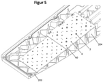
- the LEDs 4 drawn so that their positions along the horizontal can be seen. From this it follows that the LEDs 4 are arranged along the ribs 2 .
- the ribs 2 in a horizontal center area 201 which extends around the horizontal center of the light exit window, have a greater rib thickness than in a horizontal edge area 202, which is arranged horizontally on the outside of the center area 201.
- the arrangement of the LEDs 4 along the ribs 2 can ensure a particularly good heat transfer from the LEDs 4 to the ribs 2 .
- Varying the rib thickness in the different areas 201, 202 can particularly preferably promote heat dissipation from the central area 201, in which a particularly high heat development takes place, with material costs being able to be saved by providing a smaller rib thickness in the edge area 202.
- the LEDs 4 are not arranged directly on the ribs 2 but on a circuit board 40, the circuit boards 40 with the LEDs 4 and their further electrical components forming the lighting means of the described embodiment.
- This illuminant is thus placed directly on the vertical side of the ribs 2 pointing towards the light exit window and is fixed to the ribs 2 . It is fixed using screws 3 which are screwed into threaded holes 22 which are provided at at least some of the crossing points 21, which is generally particularly advantageous.
- optical elements 5 are also provided between the LEDs 4 and the light exit window, with which the light distribution emitted by the lamp can be influenced in a targeted manner. These optical elements 5 are fastened to the ribs 2 by the same fastening means, namely screws 3 and threaded bores 22, with which the circuit boards 40 are also fastened.
- the fastening means fix the at least one optical element 5 to the ribs 2, in that the optical element 5 is pressed vertically onto the light source, as a result of which the light source is pressed onto the vertical side of the ribs 2 facing the light exit window, which is generally advantageous according to the invention.
- the ribs 2 of the rib arrangement 20 have a different rib length along the vertical direction Z in different horizontal areas.
- the rib 204 has a greater extent along the vertical direction Z than the rib 203.
- the vertical extent of the ribs 2, 203, 204 changes to the extent that the vertical height of the lamp housing increases along the horizontal. This ensures that the vertical side of the ribs 2, 203, 204 facing the light exit window is at a uniform distance from the light exit window, so that all LEDs 4 have essentially the same vertical distance from the light exit window.
Landscapes
- Engineering & Computer Science (AREA)
- General Engineering & Computer Science (AREA)
- Physics & Mathematics (AREA)
- Geometry (AREA)
- Arrangement Of Elements, Cooling, Sealing, Or The Like Of Lighting Devices (AREA)
- Non-Portable Lighting Devices Or Systems Thereof (AREA)
Description
Die Erfindung betrifft eine Leuchte mit einem Leuchtengehäuse, in dem ein Kühlkörper angeordnet ist, gemäß dem Oberbegriff von Anspruch 1.The invention relates to a lamp with a lamp housing in which a heat sink is arranged, according to the preamble of
Gattungsgemäße Leuchten umfassen ein Leuchtengehäuse mit einem Innenraum und einem sich über eine horizontale Erstreckung erstreckenden Lichtaustrittsfenster. In dem Innenraum ist ein Leuchtmittel mit mehreren LEDs angeordnet, und in dem Innenraum ist ein Kühlkörper angeordnet, auf dem die LEDs angeordnet sind. Das Vorsehen eines solchen Kühlkörpers ist erforderlich, damit die von den LEDs erzeugte Wärme abgeführt werden kann. Hierzu stehen die LEDs in wärmeleitendem Kontakt mit dem Kühlkörper. Im Stand der Technik sind verschiedene Möglichkeiten bekannt, mit denen eine Leuchte mit einem Kühlkörper für LEDs realisiert werden kann. Eine sehr einfache und gleichzeitig effiziente Vorgehensweise besteht darin, ein gut wärmeleitendes Leuchtengehäuse vorzusehen, beispielsweise indem zumindest ein Teil des Leuchtengehäuses aus Metall hergestellt wird, und das Leuchtengehäuse so auszubilden, dass es an einer Seite nach außen vorstehende Kühlrippen aufweist. Bei einer Montage der LEDs in möglichst gutem wärmeleitenden Kontakt an der Seite des Innenraums des Leuchtengehäuses, an dessen Außenseite die Kühlrippen vorgesehen sind, kann das Leuchtengehäuse die Wärme der LEDs effizient aufnehmen und über die Kühlrippen an die Umgebung abgeben. Diese Vorgehensweise bringt jedoch den Nachteil mit sich, dass hierdurch eine Leuchte mit einem wenig eleganten und schwer zu reinigenden Äußeren realisiert wird. Dies ist insbesondere bei Außenleuchten, auf die sich die vorliegende Erfindung im Besonderen bezieht, nicht wünschenswert. Zur Vermeidung dieses ungewünschten Effekts ist auch bekannt, einen flächigen Kühlkörper, beispielsweise eine dicke Aluminiumplatte, in dem Leuchtengehäuse vorzusehen, auf dem die LEDs angeordnet sind und der die Wärme an den Orten, an denen die LEDs auf ihm montiert sind, punktuell aufnimmt und über seine flächige Erstreckung verteilt. Ein solcher flächiger Kühlkörper ist dann über einen möglichst großen Flächenbereich an den den Innenraum begrenzenden Seitenwänden des Leuchtengehäuses thermisch leitend angeschlossen, damit er die von den LEDs erzeugte Wärme an die Seitenwände abgibt und sie von dort aus in die Umgebung abgegeben werden kann. Bei dieser Lösung kann zwar das Vorsehen von Kühlrippen an einer Außenseite des Leuchtengehäuses vermieden werden, allerdings muss der flächige Kühlkörper als separates Bauteil gezielt so ausgebildet werden, dass er zum einen eine flächige Montageseite für die LEDs bereitstellt und zum anderen möglichst gut wärmeleitend mit möglichst großen Flächen der Seitenwände des Leuchtengehäuses verbunden werden kann. Dies erhöht zum einen die Herstellungskosten der Leuchte, zum anderen weist ein solcher für die Wärmeabfuhr optimierter separater Kühlkörper ein unschönes Erscheinungsbild auf, weshalb der Kühlkörper an Stellen, die nicht von den LEDs bedeckt sind und von außen durch das Lichtaustrittsfenster sichtbar sind, mit weiteren separaten Elementen kaschiert wird. Dies geht mit einem erheblichen Montageaufwand und erheblichen Herstellungskosten einher. Darüber hinaus ist es üblich, dass Leuchtenhersteller Leuchtenreihen anbieten, bei denen jede Leuchte dasselbe Leuchtengehäuse aufweist, bei denen jedoch je nach Anwendungszweck eine unterschiedliche Anzahl an LEDs vorgesehen ist, damit auf das jeweilige Lichtintensitätsbedürfnis eingegangen werden kann und eine Leuchte nicht mehr Energie als nötig konsumiert. Dies macht es erforderlich, dass für unterschiedliche Leuchten einer solchen Leuchtenreihe, bei denen jeweils eine unterschiedliche Anzahl an LEDs vorgesehen ist und somit das Leuchtmittel eine unterschiedliche Fläche auf dem Kühlkörper einnimmt, unterschiedliche Kaschierungsmittel vorgesehen werden müssen, da sich jeweils unterschiedlich große Bereiche des Kühlkörpers ergeben, die mittels Kaschiermittel kaschiert werden müssen, damit sie nicht von außen durch das Lichtaustrittsfenster sichtbar sind. Dies geht mit noch größeren Herstellungskosten einher. In
Der vorliegenden Erfindung liegt die Aufgabe zugrunde, eine Leuchte bereitzustellen, die zumindest eines der beschriebenen Probleme gattungsgemäßer Leuchten zumindest teilweise behebt.The object of the present invention is to provide a lamp that at least partially eliminates at least one of the described problems of generic lamps.
Als eine Lösung der der vorliegenden Erfindung zugrundeliegenden Aufgabe schlägt die Erfindung eine Leuchte mit den Merkmalen gemäß Anspruch 1 vor. Die erfindungsgemäße Leuchte umfasst ein Leuchtengehäuse mit einem Innenraum und einem sich über eine horizontale Erstreckung erstreckenden Lichtaustrittsfenster. In dem Innenraum ist zum einen ein Leuchtmittel mit mehreren LEDs angeordnet und zum anderen ein Kühlkörper angeordnet, auf dem die LEDs angeordnet sind. Das Leuchtmittel ist ein von dem Kühlkörper separates Element und wird somit bei der Herstellung der Leuchte an dem Kühlkörper angebracht. Die erfindungsgemäße Leuchte kann in verschiedenen Ausführungsformen weitere Merkmale aufweisen, die im Zusammenhang mit gattungsgemäßen Leuchten obenstehend erläutert sind. Bei der erfindungsgemäßen Leuchte weist der Kühlkörper eine Rippenanordnung mit mehreren Rippen auf, die sich innerhalb der horizontalen Erstreckung des Lichtaustrittsfensters erstreckt. Die Rippenanordnung ist dabei selbstverständlich vertikal zu dem Lichtaustrittsfenster versetzt, da die Rippenanordnung innerhalb des Innenraums angeordnet ist und das Lichtaustrittsfenster den Innenraum begrenzt. Jedoch erstreckt sich die Rippenanordnung über zumindest einen Bereich der horizontalen Erstreckung des Lichtaustrittsfensters, insbesondere über mindestens 50%, insbesondere über mindestens 70%, insbesondere über mindestens 90%, insbesondere über mindestens 100% der horizontalen Erstreckung des Lichtaustrittsfensters. Die Rippenanordnung kann sich somit auch horizontal über die Erstreckung des Lichtaustrittsfensters hinaus erstrecken. Wesentlich ist, dass die Rippenanordnung wie erläutert sich über einen nicht unerheblichen Anteil der horizontalen Erstreckung des Lichtaustrittsfensters erstreckt, da die LEDs auf der Rippenanordnung angeordnet sind und selbstverständlich bevorzugt mit Bezug auf die Horizontale fluchtend zu dem Lichtaustrittsfenster angeordnet sind. Das Vorsehen der Rippenanordnung über einen möglichst großen horizontalen Bereich kann den Vorteil mit sich bringen, dass bei einer Betrachtung der Leuchte von außen durch das Lichtaustrittsfenster sich ein durch die Rippenanordnung definiertes, gleichmäßiges Erscheinungsbild ergeben kann und dass die Wärme in dem Leuchtengehäuse besonders gut verteilt werden kann. Die Rippen liegen jeweils an der dem Lichtaustrittsfenster vertikal gegenüberliegenden, den Innenraum begrenzenden Seitenwand des Leuchtengehäuses an und bilden zwischen sich Zwischenräume aus. Die Seitenwand ist bevorzugt über die horizontale Erstreckung der Rippenanordnung hinweg flächig geschlossen ausgebildet, besonders bevorzugt erstreckt sie sich flächig geschlossen nicht nur über den horizontalen Erstreckungsbereich der Rippenanordnung hinweg sondern auch darüber hinaus. Dabei bildet diese Seitenwand bevorzugt an ihrer vom Innenraum abgewandten Seite einen Abschnitt der Außenseite des Leuchtengehäuses aus. Hierdurch kann die Wärmeabgabe mittels dieser Seitenwand, an der die Rippen angeordnet sind, zur Umgebung hin besonders begünstigt sein. Dabei weist erfindungsgemäß diese Seitenwand an ihrer Außenseite keine Rippenstruktur auf, wobei besonders bevorzugt das Leuchtengehäuse an seiner gesamten, dem Lichtaustrittsfenster vertikal gegenüberliegenden Seite ohne Rippenstruktur ausgebildet ist, besonders bevorzugt an seiner gesamten Außenseite ohne Rippenstruktur ausgebildet ist. Das Leuchtmittel ist an der zum Lichtaustrittsfenster gewandten Seite der Rippenanordnung angeordnet und liegt auf der Rippenanordnung auf. Besonders bevorzugt liegt das Leuchtmittel unmittelbar auf der Rippenanordnung auf, es können jedoch auch beispielsweise zu Montagezwecken Zwischenelemente zwischen der Rippenanordnung und dem Leuchtmittel vorgesehen sein, die dann bevorzugt möglichst gut wärmeleitend sind und sich nur innerhalb der horizontalen Erstreckung des Leuchtmittels erstrecken und die sich bevorzugt nicht über die gesamte Rippenanordnung erstrecken. Sowohl für die Wärmeleitung als auch für ein möglichst angenehmeres Erscheinungsbild der Leuchte ist es jedoch besonders vorteilhaft, dass das Leuchtmittel unmittelbar auf den Kühlrippen aufliegt. Der Kühlkörper ist erfindungsgemäß einstückig in der den Innenraum begrenzenden, dem Lichtaustrittsfenster vertikal gegenüberliegenden Seitenwand integriert. Entsprechend sind die Rippen des Kühlkörpers, die in dem Innenraum angeordnet sind, bevorzugt ausschließlich innerhalb des Innenraums angeordnet sind, einstückig in dem Gehäuseteil des Leuchtengehäuses integriert, das diese Seitenwand umfasst, insbesondere unmittelbar einstückig mit diesem Gehäuseteil des Leuchtengehäuses hergestellt. Besonders bevorzugt weist das Leuchtengehäuse einen ersten, wannenförmigen Gehäuseteil auf, der einen Bodenabschnitt aufweist, wobei der Bodenabschnitt durch die dem Lichtaustrittsfenster vertikal gegenüberliegende, den Innenraum begrenzende Seitenwand ausgebildet ist. Ferner weist bevorzugt das Leuchtengehäuse einen zweiten, als Abdeckung ausgebildeten Gehäuseteil auf, der das Lichtaustrittsfenster umfasst. Besonders bevorzugt sind die beiden Gehäuseteile in unterschiedlichen Verfahrensschritten und insbesondere aus unterschiedlichen Materialien hergestellt. Beispielsweise kann der erste Gehäuseteil mittels Metallguss und der zweite Gehäuseteil mittels Spritzguss hergestellt sein. Erfindungsgemäß sind die Gehäuseteile abdichtend miteinander verbunden unter Ausbildung eines abgedichteten Innenraums, bevorzugt abgedichtet gemäß Norm IP64, bevorzugt IP65.As a solution to the problem on which the present invention is based, the invention proposes a lamp with the features according to
Die erfindungsgemäße Leuchte weist im Vergleich zu herkömmlichen Leuchten wesentliche Vorteile auf. Durch das Vorsehen einer Rippenanordnung innerhalb des Innenraums ist zum einen die Realisierung einer Leuchte ohne außenliegende Rippen ermöglicht, was für einen angenehmen Gesamteindruck der Leuchte vorteilhaft ist. Zum anderen ermöglicht die Rippenanordnung eine gute Wärmeverteilung in dem Leuchtengehäuse, so dass die Wärme in dem Leuchtengehäuse an die den Innenraum begrenzenden Seitenwände gelangen kann und durch diese an die Umgebung abgegeben werden. Darüber hinaus ist die erfindungsgemäße Leuchte besonders einfach und kostengünstig herstellbar, da die Rippenanordnung auf einfache Weise mit der dem Lichtaustrittsfenster gegenüberliegenden Seitenwand integriert hergestellt werden kann. Dabei hat es sich als besonders vorteilhaft herausgestellt, das Leuchtengehäuse so herzustellen, dass es einen ersten Gehäuseteil umfasst, der nach Art einer Wanne ausgebildet ist. In einem solchen Gehäuseteil können auf einfache Weise Komponenten der Leuchte, beispielsweise Betriebsgerät, Leitungskabel und das Leuchtmittel, montiert werden, wonach anschließend ein solcher Gehäuseteil auf einfache Weise durch eine Abdeckung verschlossen werden kann. Als besonders bevorzugt hat es sich allgemein herausgestellt, die Rippenanordnung so vorzusehen, dass die Zwischenräume an ihrer zum Lichtaustrittsfenster gewandten Seite offen sind. Besonders bevorzugt sind die Rippen der Rippenanordnung so ausgebildet, dass sie mit Bezug auf die Horizontale jeweils eine Rippenstärke und eine Rippenlänge aufweisen und sich über eine vertikale Erstreckung hinweg erstrecken, wobei die Rippenstärke einer jeweiligen Rippe an dem zum Lichtaustrittsfenster gewandten vertikalen Ende der jeweiligen Rippe ihren geringsten Betrag aufweist. Dies ist für die Entformbarkeit bei der Herstellung des Gehäuseteils, der die den Innenraum begrenzende Seitenwand und die Rippen umfasst, besonders vorteilhaft. Die Rippen bilden bevorzugt mit ihrem zum Lichtaustrittsfenster gewandten vertikalen Ende eine Umrandung des jeweiligen Zwischenraums aus, der von ihnen umschlossen ist. Besonders bevorzugt ist der Zwischenraum an seinem zur Seitenwand, die dem Lichtaustrittsfenster vertikal gegenüberliegt und den Innenraum gebrenzt, gewandten Ende vollständig geschlossen, wobei an diesem Ende die Rippen diesen Zwischenraum bevorzugt umfänglich geschlossen umschließen. Besonders bevorzugt ist der Zwischenraum ausschließlich an seinem zum Lichtaustrittsfenster gewandten vertikalen Ende offen.The lamp according to the invention has significant advantages compared to conventional lamps. The provision of a rib arrangement within the interior makes it possible to realize a lamp without external ribs, which is advantageous for a pleasant overall impression of the lamp. On the other hand, the arrangement of ribs enables good heat distribution in the lamp housing, so that the heat in the lamp housing can reach the side walls delimiting the interior space and be emitted through them to the environment. In addition, the lamp according to the invention can be produced particularly simply and inexpensively, since the arrangement of ribs can be produced in a simple manner integrated with the side wall opposite the light emission window. It has proven to be particularly advantageous to produce the lamp housing in such a way that it includes a first housing part which is designed in the manner of a trough. In such a housing part, components of the lamp, for example control gear, cable and the lamp, can be mounted in a simple manner, after which such a housing part can then be easily closed with a cover. It has generally turned out to be particularly preferred to provide the arrangement of ribs in such a way that the intermediate spaces are open on their side facing the light exit window. The ribs are particularly preferred Rib arrangement designed so that they each have a rib thickness and a rib length with respect to the horizontal and extend over a vertical extent, the rib thickness of a respective rib at the vertical end of the respective rib facing the light exit window having its smallest amount. This is particularly advantageous for the ability to demould during production of the housing part, which includes the side wall delimiting the interior space and the ribs. With their vertical end facing the light exit window, the ribs preferably form a border of the respective intermediate space which is enclosed by them. Particularly preferably, the intermediate space is completely closed at its end facing the side wall, which is vertically opposite the light exit window and delimits the interior space, with the ribs at this end preferably enclosing this intermediate space in a closed manner. The intermediate space is particularly preferably open only at its vertical end facing the light exit window.
In einer Ausführungsform sind die Rippen der Rippenanordnung unter Ausbildung eines regelmäßigen Musters angeordnet. Besonders bevorzugt ist das regelmäßige Muster ein Wabenmuster oder ein sonstiges Kreuzgittermuster. Die Ausbildung der Rippenanordnung als regelmäßiges Muster kann zum einen eine möglichst homogene Wärmeverteilung begünstigen, zum anderen ist dies dahingehend besonders vorteilhaft, dass ein Betrachter von außen durch das Lichtaustrittsfenster hindurch das regelmäßige Muster sieht und als angenehm wahrnimmt, wenn das Leuchtmittel die Rippenanordnung nur teilweise bedeckt. Dies ist besonders vorteilhaft, wenn das Leuchtengehäuse zur Realisierung von unterschiedlichen Leuchten einer Leuchtenreihe verwendet wird, da dann unabhängig von der horizontalen Erstreckung des Leuchtmittels der jeweiligen Leuchte der Leuchtenreihe stets ein Betrachter von außen durch das Lichtaustrittsfenster hindurch den horizontalen neben dem Leuchtmittel angeordneten Bereich der Rippenanordnung als regelmäßiges Muster und somit optisch angenehm wahrnimmt.In one embodiment, the ribs of the rib arrangement are arranged to form a regular pattern. The regular pattern is particularly preferably a honeycomb pattern or some other cross-lattice pattern. The formation of the arrangement of ribs as a regular pattern can on the one hand promote the most homogeneous possible heat distribution, and on the other hand this is particularly advantageous in that an observer from the outside sees the regular pattern through the light emission window and perceives it as pleasant if the light source only partially covers the arrangement of ribs . This is particularly advantageous if the luminaire housing is used to implement different luminaires in a row of luminaires, since then, regardless of the horizontal extent of the illuminant of the respective luminaire in the row of luminaires, an observer from the outside can always see through the light exit window through the horizontal area of the rib arrangement arranged next to the illuminant as a regular pattern and thus optically pleasant.
In einer Ausführungsform kreuzen sich die Rippen der Rippenanordnung als Kreuzungsstellen. Besonders bevorzugt gehen die Rippen der Rippenanordnung an Kreuzungsstellen ineinander über. Besonders bevorzugt erstrecken sich die Kreuzungsstellen über die gesamte vertikale Erstreckung der sich an der jeweiligen Kreuzungsstelle kreuzenden Rippen. Besonders bevorzugt bilden die Kreuzungsstellen jeweils die Eckpunkte der Zwischenräume zwischen den Rippen, wobei jeder der Zwischenräume horizontal umfänglich von den ihn begrenzenden Rippen umschlossen ist, vertikal von der dem Lichtaustrittsfenster gegenüberliegenden, den Innenraum begrenzenden Seitenwand geschlossen ist und an seiner zum Lichtaustrittsfenster gewandten vertikalen Seite offen ist. Die Kreuzungsstellen haben dabei eine horizontale Erstreckung, die sich aus dem Kreuzen bzw. Ineinanderlaufen der jeweiligen Rippen ergibt. Durch die entsprechende Ausgestaltung der Rippenanordnung kann zum einen eine robuste Rippenanordnung bereitgestellt sein, mit der auch das Gehäuse gefestigt sein kann. Zum anderen kann hierdurch eine besonders gute Wärmeverteilung gewährleistet sein, und darüber hinaus kann hierdurch ein gleichmäßiges Erscheinungsbild gewährleistet sein.In one embodiment, the ribs of the rib arrangement intersect as crossing points. The ribs of the rib arrangement particularly preferably merge into one another at crossing points. The crossing points particularly preferably extend over the entire vertical extension of the ribs crossing at the respective crossing point. Particularly preferably, the crossing points each form the corner points of the spaces between the ribs, with each of the spaces being horizontally circumferentially enclosed by the ribs delimiting it, being closed vertically by the side wall opposite the light exit window and delimiting the interior space and being open on its vertical side facing the light exit window is. The crossing points have a horizontal extent, which results from the crossing or merging of the respective ribs. Through the appropriate design of the rib arrangement, on the one hand a robust rib arrangement can be provided, with which the housing can also be strengthened. On the other hand, a particularly good distribution of heat can be ensured in this way, and moreover a uniform appearance can be ensured in this way.
Allgemein sind besonders bevorzugt die LEDs entlang der Rippen angeordnet. Durch das Anordnen der LEDs entlang der Rippen, d. h. innerhalb des horizontalen Erstreckungsbereichs der Rippen, kann eine besonders gute Wärmeabfuhr der LEDs in die Rippen gewährleistet sein, da die LEDs somit vertikal oberhalb der Rippen angeordnet sind und die Wärme direkt an die Rippen abgeben können. Besonders bevorzugt sind die LEDs ausschließlich entlang der Rippen und nicht entlang der zwischen den Rippen ausgebildeten Zwischenräume angeordnet.In general, the LEDs are particularly preferably arranged along the ribs. By arranging the LEDs along the ribs, ie within the horizontal extent of the ribs, a particularly good heat dissipation of the LEDs into the ribs can be ensured, since the LEDs are thus arranged vertically above the ribs and can give off the heat directly to the ribs. Most preferably, the LEDs are solely along the ribs and not along those formed between the ribs spaces arranged.
In einer Ausführungsform ist das Leuchtmittel an zumindest einigen der Rippen befestigt. Besonders bevorzugt erfolgt die Befestigung an den Rippen über Befestigungsmittel, die an einer zu dem Lichtaustrittsfenster gewandten Seite dieser Rippen angeordnet sind, an denen das Leuchtmittel befestigt ist. Beispielsweise können die Befestigungsmittel in den Rippen vorgesehene Bohrungen oder in den Rippen integrierte Gewindestifte umfassen, wobei beispielsweise das Leuchtmittel über Muttern an den Gewindestiften oder über Schrauben in den Bohrungen an den Rippen befestigt ist. Besonders bevorzugt ist das Leuchtmittel ausschließlich an den Rippen befestigt. Dies kann zum einen lichttechnisch vorteilhaft sein, zum anderen kann dies zur Gewährleistung einer möglichst guten Wärmeübertragung von dem Leuchtmittel in die Rippen vorteilhaft sein. Besonders bevorzugt ist die Rippenanordnung von einem ersten Gehäuseteil des Leuchtengehäuses umfasst, in dem das Leuchtmittel angeordnet ist, wobei das Leuchtengehäuse einen zweiten Gehäuseteil umfasst, der als Abdeckung ausgebildet und an dem ersten Gehäuseteil befestigt ist. Besonders bevorzugt ist der zweite Gehäuseteil an dem ersten Gehäuseteil abdichtend und lösbar befestigt. Besonders bevorzugt sind die Befestigungsmittel nach Demontage des zweiten Gehäuseteils vom ersten Gehäuseteil an einer Seite des ersten Gehäuseteils, die dem Lichtaustrittsfenster in der Leuchte vertikal gegenüberliegt, vertikal zugänglich. Besonders bevorzugt ist ferner ein Optikelement, das zwischen den LEDs und dem Lichtaustrittsfenster angeordnet ist, an zumindest einigen der Rippen befestigt, insbesondere ausschließlich an den Rippen befestigt, insbesondere über Befestigungsmittel, die an einer zu dem Lichtaustrittsfenster gewandten Seite dieser Rippen angeordnet sind, an denen das Optikelement befestigt ist. Besonders bevorzugt sind Leuchtmittel und Optikelement über dieselben Befestigungsmittel an denselben Rippen befestigt. Das Optikelement kann an den Rippen in verschiedenen Ausführungsformen auf analoge Weise befestigt sein, wie dies im Hinblick auf die Befestigung des Leuchtmittels an den Rippen erläutert wurde.In one embodiment, the illuminant is attached to at least some of the ribs. Fastening to the ribs is particularly preferably carried out using fastening means which are arranged on a side of these ribs which faces the light exit window and on which the lighting means is fastened. For example, the fastening means can comprise bores provided in the ribs or threaded pins integrated in the ribs, with the illuminant being fastened to the threaded pins by nuts or by screws in the bores on the ribs, for example. The illuminant is particularly preferably attached exclusively to the ribs. On the one hand, this can be advantageous in terms of lighting technology, and on the other hand, this can be advantageous for ensuring the best possible heat transfer from the lighting means into the ribs. The rib arrangement is particularly preferably comprised of a first housing part of the lamp housing, in which the lamp is arranged, the lamp housing comprising a second housing part which is designed as a cover and is fastened to the first housing part. Particularly preferably, the second housing part is attached to the first housing part in a sealing and detachable manner. Particularly preferably, after the second housing part has been removed from the first housing part, the fastening means are vertically accessible on a side of the first housing part which is vertically opposite the light exit window in the luminaire. Also particularly preferred is an optical element, which is arranged between the LEDs and the light exit window, attached to at least some of the ribs, in particular only attached to the ribs, in particular via attachment means, which are arranged on a side of these ribs facing the light exit window, on which the optical element is attached. Lamps and optical elements are particularly preferred via the same fastening means on the same ribs attached. In various embodiments, the optical element can be attached to the ribs in a manner analogous to that explained with regard to the attachment of the illuminant to the ribs.
In einer Ausführungsform ist das Leuchtmittel als PCB (printed circuit board) bzw. Platine ausgebildet und unmittelbar an zumindest einigen Rippen der Rippenanordnung befestigt. Eine PCB umfasst einen Träger, auf dem zumindest Leiterbahnen und die LEDs angeordnet sind. Beispielsweise sind PCBs bekannt, bei denen der Träger als flexible Leiterplatte ausgebildet ist oder PCBs, die als Träger eine Leiterplatte mit einem Metallkern umfasst ("metal-core PCB") oder bei denen ein Träger aus einem Epoxid-Material vorgesehen ist. In einer Ausführungsform umfasst das Leuchtmittel elektrische Leiterbahnen, die direkt auf zumindest einigen Rippen der Rippenanordnung aufgebracht sind. Dies kann beispielsweise durch eine Gravur oder durch Bedrucken der Rippen erfolgen. Beispielsweise können die Rippen in einem Gehäuseteil integriert sein, das aus einem Metall hergestellt ist, wobei die Rippen anschließend mit einem Isolationsmaterial beschichtet werden und dann die Leiterbahnen auf die Rippen aufgebracht werden. Beispielsweise können die Rippen in einem Gehäuseteil integriert sein, der aus Kunststoff hergestellt ist, wobei die Leiterbahnen direkt auf diese aus Kunststoff hergestellten Rippen aufgebracht sind.In one embodiment, the lighting means is designed as a PCB (printed circuit board) or circuit board and is attached directly to at least some ribs of the rib arrangement. A PCB includes a carrier on which at least conductor tracks and the LEDs are arranged. For example, PCBs are known in which the carrier is in the form of a flexible printed circuit board or PCBs which include a printed circuit board with a metal core ("metal-core PCB") as the carrier or in which a carrier made of an epoxy material is provided. In one embodiment, the lighting means includes electrical conductor tracks that are applied directly to at least some ribs of the rib arrangement. This can be done, for example, by engraving or by printing the ribs. For example, the ribs can be integrated into a housing part that is made of a metal, with the ribs then being coated with an insulating material and then the conductor tracks being applied to the ribs. For example, the ribs can be integrated in a housing part made of plastic, with the conductor tracks being applied directly to these ribs made of plastic.
Erfindungsgemäß erstreckt sich die Rippenanordnung mit einem horizontalen Abschnitt über das Leuchtmittel hinaus, wobei dieser horizontale Abschnitt der Rippenanordnung innerhalb der horizontalen Erstreckung des Lichtaustrittsfensters liegt und insbesondere zumindest teilweise von außen durch das Lichtaustrittsfenster hindurch sichtbar ist. Bei dieser Ausführungsform ist die Rippenanordnung so großflächig ausgestaltet, dass sie sich mit Bezug auf die Horizontale über das Leuchtmittel hinaus erstreckt und dabei bevorzugt bei einer Betrachtung durch das Lichtaustrittsfenster von außen sichtbar ist. Dabei wird auf einen Blickwinkel abgestellt, der senkrecht zur Horizontalen auf das Lichtaustrittsfenster erfolgt. Bei dieser Ausführungsform ist zum einen die Rippenanordnung großflächig ausgestaltet, wodurch eine sehr gute Wärmeverteilung ermöglicht ist. Darüber hinaus kann durch das Vorsehen einer entsprechend großflächigen Rippenanordnung ein optisch ansprechender Gesamteindruck gewährleistet sein, wenn ein Betrachter die Leuchte von der Seite des Lichtaustrittsfensters aus durch das Lichtaustrittsfenster hindurch betrachtet.According to the invention, the rib arrangement extends with a horizontal section beyond the lamp, this horizontal section of the rib arrangement lying within the horizontal extent of the light exit window and in particular being at least partially visible from the outside through the light exit window. In this embodiment, the rib arrangement is designed so large that they extends beyond the illuminant with respect to the horizontal and is preferably visible from the outside when viewed through the light exit window. This is based on a viewing angle that is perpendicular to the horizontal to the light exit window. In this embodiment, on the one hand, the rib arrangement has a large surface area, which enables very good heat distribution. In addition, the provision of a correspondingly large-area rib arrangement can ensure a visually appealing overall impression when an observer looks at the luminaire from the side of the light exit window through the light exit window.
In einer Ausführungsform weisen die Rippen eine Rippenstärke und eine Rippenlänge auf, über die sie sich in einer horizontalen Ebene erstrecken, wobei in unterschiedlichen horizontalen Abschnitten der Rippenanordnung jeweils unterschiedliche Rippenstärken vorgesehen sind. In einer Ausführungsform sind Rippenstärke und Rippenlänge einer jeden Rippe über ihren vertikalen Erstreckungsbereich konstant, in einer anderen Ausführungsform können diese Stärken entlang der Vertikalen variieren. In dieser Ausführungsform ist bei einer Variation von Rippenstärke und Rippenlänge auf den gemittelten Wert, gemittelt über die vertikale Erstreckung der jeweiligen Rippe, abgestellt. Besonders bevorzugt verjüngt sich die Rippenstärke und insbesondere ihre Rippenlänge der Rippen entlang der Vertikalen ausgehend von der dem Lichtaustrittsfenster gegenüberliegenden Seitenwand zum Lichtaustrittsfenster hin. Besonders bevorzugt weist eine erste Gruppe an Rippen eine größere vertikale Erstreckung auf als eine zweite Gruppe an Rippen, wobei die erste Gruppe an Rippen eine größere Rippenstärke aufweist als die zweite Gruppe an Rippen. Besonders bevorzugt ist die Rippenstärke der Rippen in einem horizontalen Mittenbereich, der sich um die horizontale Mitte der Lichtaustrittsöffnung erstreckt, größer als in einem horizontalen Randbereich, der horizontal außen an dem Mittenbereich angeordnet ist. Der Mittenbereich ist bevorzugt symmetrisch um die horizontale Mitte der Lichtaustrittsöffnung verteilt. Der Mittenbereich beträgt bevorzugt zumindest 20% der horizontalen Erstreckung der Rippenanordnung. Durch das Vorsehen von unterschiedlichen Rippenstärken kann die Wärmeableitung, die durch die jeweilige Rippe gewünscht ist, gezielt eingestellt sein.In one embodiment, the ribs have a rib thickness and a rib length over which they extend in a horizontal plane, with different rib thicknesses being provided in different horizontal sections of the rib arrangement. In one embodiment, the rib thickness and rib length of each rib are constant over its vertical extent, in another embodiment these thicknesses may vary along the vertical. In this embodiment, when there is a variation in rib thickness and rib length, the mean value, averaged over the vertical extension of the respective rib, is taken into account. Particularly preferably, the rib thickness and in particular the rib length of the ribs tapers along the vertical, starting from the side wall opposite the light exit window towards the light exit window. A first group of ribs particularly preferably has a greater vertical extent than a second group of ribs, the first group of ribs having a greater rib thickness than the second group of ribs. Particularly preferred is the rib thickness of the ribs in a horizontal central area around the horizontal Extends the middle of the light exit opening, greater than in a horizontal edge area, which is arranged horizontally on the outside of the central area. The center area is preferably distributed symmetrically around the horizontal center of the light exit opening. The central area is preferably at least 20% of the horizontal extent of the rib arrangement. By providing different rib thicknesses, the heat dissipation that is desired through the respective rib can be adjusted in a targeted manner.
In einer Ausführungsform weist das Leuchtengehäuse eine vertikale Höhe auf, die sich innerhalb eines Bereichs der horizontalen Erstreckung der Rippenanordnung verändert, insbesondere über die gesamte Rippenanordnung hinweg verändert, d. h. über die gesamte horizontale Erstreckung der Rippenanordnung hinweg verändert. Eine vertikale Erstreckung der Rippen der Rippenanordnung innerhalb dieses Bereichs nimmt bevorzugt in demselben Maße zu wie die vertikale Höhe des Leuchtengehäuses. Hierdurch kann gewährleistet sein, dass eine zum Lichtaustrittsfenster gewandte Seite der Rippenanordnung, die durch die zum Lichtaustrittsfenster gewandte Seite der Rippen gebildet ist, innerhalb dieses Bereichs einen konstanten Abstand zum Lichtaustrittfenster aufweist. Die Rippenanordnung kann somit eine Höhennivellierung bereitstellen, so dass das Leuchtmittel über seine horizontale Erstreckung hinweg einen zumindest im Wesentlichen gleichmäßigen Abstand zum Lichtaustrittsfenster aufweist.In one embodiment, the lamp housing has a vertical height which varies within a range of the horizontal extent of the rib arrangement, in particular varies over the entire rib arrangement, i. H. varied throughout the horizontal extent of the rib assembly. A vertical extent of the ribs of the rib arrangement within this range preferably increases to the same extent as the vertical height of the lamp housing. This can ensure that a side of the rib arrangement facing the light exit window, which is formed by the side of the ribs facing the light exit window, is at a constant distance from the light exit window within this area. The rib arrangement can thus provide height adjustment, so that the lighting means has an at least essentially uniform distance from the light exit window over its horizontal extension.
Allgemein ist besonders bevorzugt die dem Lichtaustrittsfenster vertikal gegenüberliegende Seitenwand gemeinsam mit der Rippenanordnung mittels eines Gießverfahrens einstückig hergestellt, besonders bevorzugt ist der genannte erste, wannenförmige Gehäuseteil mittels eines Gießverfahrens hergestellt. Besonders bevorzugt handelt es sich dabei um ein Metallgussverfahren, insbesondere um einen Metalldruckguss.In general, the side wall vertically opposite the light exit window is particularly preferably produced in one piece together with the rib arrangement by means of a casting process; the first, trough-shaped housing part mentioned is particularly preferably produced by means of a casting process. This is particularly preferably a metal casting process, in particular a die-cast metal.
Die Erfindung wird nachfolgend anhand eines Ausführungsbeispiels unter Bezugnahme auf fünf Figuren näher erläutert.The invention is explained in more detail below using an exemplary embodiment with reference to five figures.
Es zeigen:
- Figur 1:
- in einer Prinzipdarstellung eine Ansicht eines Elements einer ersten erfindungsgemäßen Ausführungsform;
- Figur 2:
- in einer Prinzipdarstellung eine weitere Ansicht des
Elements gemäß Figur 1 ; - Figur 3:
- in einer Prinzipdarstellung eine weitere Ansicht des
Elements gemäß Figur 1 ; - Figur 4:
- in einer Prinzipdarstellung eine Ansicht mehrerer Elemente der Ausführungsform gemäß
Figur 1 ; - Figur 5:
- in einer Prinzipdarstellung eine Ansicht mehrerer Elemente der Ausführungsform gemäß
Figur 1
- Figure 1:
- in a schematic representation a view of an element of a first embodiment according to the invention;
- Figure 2:
- in a principle representation a further view of the element according to
figure 1 ; - Figure 3:
- in a principle representation a further view of the element according to
figure 1 ; - Figure 4:
- in a schematic representation a view of several elements of the embodiment
figure 1 ; - Figure 5:
- in a schematic representation a view of several elements of the embodiment
figure 1 .
In den
Bei dem erfindungsgemäßen Ausführungsbeispiel weist das Leuchtengehäuse einen ersten Gehäuseteil 1 auf, der wannenförmig ausgebildet ist. Dieser erste Gehäuseteil 1 weist eine vertikale Höhe entlang einer Vertikalrichtung Z auf, die sich über die horizontale Erstreckung des ersten Gehäuseteils 1 hinweg verändert. Die Vertikale steht senkrecht auf jeglicher horizontaler Ebene. Wie insbesondere aus
In dem ersten Gehäuseteil 1 ist integriert eine Rippenanordnung 20 vorgesehen, die Rippen 2 aufweist, die sich ausgehend von der Seitenwand 10 vertikal zum Lichtaustrittsfenster hin und somit zur Oberseite des ersten Gehäuseteils 1 hin erstrecken. Wie insbesondere aus der Zusammenschau der
Die LEDs 4 sind bei dem beschriebenen Ausführungsbeispiel nicht unmittelbar auf den Rippen 2 angeordnet sondern auf einer Platine 40, wobei die Platinen 40 mit den LEDs 4 und ihren weiteren elektrischen Komponenten das Leuchtmittel der beschriebenen Ausführungsform ausbilden. Dieses Leuchtmittel ist somit unmittelbar auf die zum Lichtaustrittsfenster weisende vertikale Seite der Rippen 2 aufgelegt und an den Rippen 2 fixiert. Die Fixierung erfolgt über Schrauben 3, die in Gewindebohrungen 22 eingeschraubt sind, die an zumindest einigen der Kreuzungsstellen 21 vorgesehen sind, was allgemein besonders vorteilhaft ist. Bei der beschriebenen Ausführungsform sind ferner Optikelemente 5 zwischen den LEDs 4 und dem Lichtaustrittsfenster vorgesehen, mit denen die von der Leuchte ausgesandte Lichtverteilung gezielt beeinflusst werden kann. Diese Optikelemente 5 sind durch dieselben Befestigungsmittel, nämlich Schrauben 3 und Gewindebohrungen 22, an den Rippen 2 befestigt, mit denen auch die Platinen 40 befestigt sind.In the exemplary embodiment described, the
Denn durch die Befestigungsmittel erfolgt eine Fixierung des zumindest einen Optikelements 5 an den Rippen 2, indem das Optikelement 5 vertikal auf das Leuchtmittel gepresst wird, wodurch das Leuchtmittel auf die zum Lichtaustrittsfenster gewandte vertikale Seite der Rippen 2 gepresst wird, was erfindungsgemäß allgemein vorteilhaft ist.This is because the fastening means fix the at least one
Insbesondere aus
- 11
- erster Gehäuseteilfirst housing part
- 22
- Ripperib
- 33
- Schraubescrew
- 44
- LEDLEDs
- 55
- Optikelementoptical element
- 1010
- SeitenwandSide wall
- 2020
- Rippenanordnungrib arrangement
- 2121
- Kreuzungsstellecrossing point
- 2222
- Gewindebohrungthreaded hole
- 4040
- Platinecircuit board
- 201201
- horizontaler Mittenbereichhorizontal center area
- 202202
- horizontaler Randbereichhorizontal edge area
- 203203
- Ripperib
- 204204
- Ripperib
- ZZ
- Vertikalrichtungvertical direction
Claims (10)
- Light comprising a light housing with an interior space and a light emission window extending over a horizontal extent, wherein an illuminant comprising a plurality of LEDs (4) is arranged in the interior space and a heat sink on which the LEDs (4) are arranged is arranged in the interior space, wherein the heat sink has a rib arrangement (20) with a plurality of fins (2, 203, 204), which extends within the horizontal extent of the light emission window, wherein the fins (2, 203, 204) each bear against the side wall (10) of the light housing which is vertically opposite the light emission window and bounds the interior space and form intermediate spaces between them, wherein the illuminant rests on the side of the rib arrangement (20) facing the light emission window, wherein the heat sink arranged in the interior space is integrated in one piece in the side wall (10) bounding the interior space and this side wall (10) does not have a rib structure on its outer side, the side wall (10) forming a bottom section of a first, trough-shaped housing part (1) of the light housing and the light emission window being enclosed by a second housing part designed as a cover, the housing parts (1) being connected to one another in a sealing manner, forming the interior space as a sealed interior space,
characterized in that
the rib arrangement (20) extends with a horizontal section beyond the illuminant, this horizontal section of the rib arrangement (20) lying within the horizontal extension of the light emission window. - Light according to claim 1,
characterized in that
the fins (2, 203, 204) of the rib arrangement (20) are arranged to form a regular pattern, the pattern being in particular a honeycomb pattern or other cross-grid pattern. - Light according to any of the preceding claims, characterized in that
the fins (2, 203, 204) of the rib arrangement (20) intersect at intersection points (21), wherein in particular the intersection points (21) each form the corner points of the intermediate spaces between the fins (2, 203, 204) and each of the intermediate spaces is horizontally circumferentially enclosed by the fins (2, 203, 204) bounding it, is vertically closed by the side wall (10) opposite the light emission window and is open on its vertical side facing the light emission window. - Light according to any of the preceding claims, characterized in that
the LEDs (4) are arranged along the fins (2, 203, 204). - Light according to any of the preceding claims, characterized in that
the illuminant and in particular an optical element (5) arranged between the LEDs (4) and the light emission window is fixed to at least some of the fins (2, 203, 204), in particular via fixing means (3, 22) arranged on a side of these fins (2, 203, 204) facing the light emission window. - Light according to claim 5,
characterized in that
the illuminant is formed as a PCB and is directly attached to at least some fins (2, 203, 204) of the rib arrangement (20) or that the illuminant comprises electrical conductor tracks which are directly applied to at least some fins (2, 203, 204) of the rib arrangement (20). - Light according to any of the preceding claims, characterized in that
the horizontal portion of the rib arrangement (20), with which it extends beyond the illuminant, is visible from the outside through the light emission window. - Light according to any one of the preceding claims, characterized in that
the fins (2, 203, 204) have a rib thickness and a rib length over which they extend horizontally, different rib thicknesses being respectively provided in different horizontal sections of the rib arrangement (20), the rib thickness of the fins (2, 203, 204) in particular being greater in a horizontal center region (201) extending around the horizontal center of the light exit opening than in a horizontal edge region (202) arranged horizontally on the outside of the center region (201). - Light according to any one of the preceding claims, characterized in that
the light housing has a vertical height which varies within a region of the horizontal extension of the rib arrangement (20), wherein a vertical extension of the fins (2, 203, 204) of the rib arrangement (20) increases within this region to the same extent as the vertical height of the light housing, so that a side of the rib arrangement (20) facing the light emission window, which is formed by the side of the fins (2, 203, 204) facing the light emission window, has a constant distance to the light emission window within this region. - Light according to any of the preceding claims, characterized in that
the side wall (10) together with the rib arrangement (20), in particular the first, trough-shaped housing part (1), is produced in one piece by means of a casting process, in particular a metal casting process.
Applications Claiming Priority (1)
| Application Number | Priority Date | Filing Date | Title |
|---|---|---|---|
| DE102018133500.8A DE102018133500A1 (en) | 2018-12-21 | 2018-12-21 | Luminaire with cooling fins in the luminaire housing |
Publications (2)
| Publication Number | Publication Date |
|---|---|
| EP3671035A1 EP3671035A1 (en) | 2020-06-24 |
| EP3671035B1 true EP3671035B1 (en) | 2022-02-09 |
Family
ID=69411055
Family Applications (1)
| Application Number | Title | Priority Date | Filing Date |
|---|---|---|---|
| EP19218415.8A Active EP3671035B1 (en) | 2018-12-21 | 2019-12-20 | Light with cooling fins in the light housing |
Country Status (2)
| Country | Link |
|---|---|
| EP (1) | EP3671035B1 (en) |
| DE (1) | DE102018133500A1 (en) |
Citations (10)
| Publication number | Priority date | Publication date | Assignee | Title |
|---|---|---|---|---|
| JPH05206339A (en) | 1992-01-27 | 1993-08-13 | Matsushita Electric Ind Co Ltd | Heat sink |
| CN201487718U (en) | 2009-09-03 | 2010-05-26 | 黄金鹿 | LED street lamp with integrated functions of refraction, reflection and light distribution |
| CN201935071U (en) | 2011-01-19 | 2011-08-17 | 昆山华英光宝科技有限公司 | Racquet type street lamp |
| DE102010054592A1 (en) | 2010-12-15 | 2012-06-21 | Autev Ag | Cooling device for cooling of components by flow of medium, has cooling plate on which cooling fins is arranged in radial direction of cooling plate |
| CN203024030U (en) | 2012-11-14 | 2013-06-26 | 厦门飞华隆智能科技有限公司 | High-power solar energy LED (Light Emitting Diode) street lamp head |
| DE202013102667U1 (en) | 2013-06-20 | 2013-07-09 | Stührenberg GmbH Elektrobau-Signaltechnik | Lamp housing with heat dissipation structure |
| EP2779652A1 (en) | 2013-03-14 | 2014-09-17 | ABL IP Holding LLC | Veiling zone control |
| CN204922732U (en) | 2015-07-16 | 2015-12-30 | 湖南亚珺光电科技有限公司 | High -efficient street lamp that purifies of air |
| KR101727908B1 (en) | 2015-02-03 | 2017-04-18 | 엘지전자 주식회사 | Lighting device for streetlamp |
| WO2018214804A1 (en) * | 2017-05-25 | 2018-11-29 | 苏州欧普照明有限公司 | Lamp |
Family Cites Families (6)
| Publication number | Priority date | Publication date | Assignee | Title |
|---|---|---|---|---|
| US8465178B2 (en) * | 2010-09-07 | 2013-06-18 | Cree, Inc. | LED lighting fixture |
| KR101000014B1 (en) * | 2010-10-11 | 2010-12-09 | 주식회사 금영 | Led streetlight device |
| TWM423207U (en) * | 2011-10-13 | 2012-02-21 | Yi-Ming Chen | Heat-dissipation structure for light bulb |
| KR101376079B1 (en) * | 2013-12-23 | 2014-03-19 | 주식회사 금영 | The led guard lamp |
| CA2950283C (en) * | 2014-05-30 | 2023-09-05 | Hubbell Incorporated | Area luminaire with heat fins |
| US10260729B2 (en) * | 2017-01-16 | 2019-04-16 | Lumca Inc. | LED lighting fixture |
-
2018
- 2018-12-21 DE DE102018133500.8A patent/DE102018133500A1/en active Pending
-
2019
- 2019-12-20 EP EP19218415.8A patent/EP3671035B1/en active Active
Patent Citations (10)
| Publication number | Priority date | Publication date | Assignee | Title |
|---|---|---|---|---|
| JPH05206339A (en) | 1992-01-27 | 1993-08-13 | Matsushita Electric Ind Co Ltd | Heat sink |
| CN201487718U (en) | 2009-09-03 | 2010-05-26 | 黄金鹿 | LED street lamp with integrated functions of refraction, reflection and light distribution |
| DE102010054592A1 (en) | 2010-12-15 | 2012-06-21 | Autev Ag | Cooling device for cooling of components by flow of medium, has cooling plate on which cooling fins is arranged in radial direction of cooling plate |
| CN201935071U (en) | 2011-01-19 | 2011-08-17 | 昆山华英光宝科技有限公司 | Racquet type street lamp |
| CN203024030U (en) | 2012-11-14 | 2013-06-26 | 厦门飞华隆智能科技有限公司 | High-power solar energy LED (Light Emitting Diode) street lamp head |
| EP2779652A1 (en) | 2013-03-14 | 2014-09-17 | ABL IP Holding LLC | Veiling zone control |
| DE202013102667U1 (en) | 2013-06-20 | 2013-07-09 | Stührenberg GmbH Elektrobau-Signaltechnik | Lamp housing with heat dissipation structure |
| KR101727908B1 (en) | 2015-02-03 | 2017-04-18 | 엘지전자 주식회사 | Lighting device for streetlamp |
| CN204922732U (en) | 2015-07-16 | 2015-12-30 | 湖南亚珺光电科技有限公司 | High -efficient street lamp that purifies of air |
| WO2018214804A1 (en) * | 2017-05-25 | 2018-11-29 | 苏州欧普照明有限公司 | Lamp |
Non-Patent Citations (1)
| Title |
|---|
| PRYDE JAMES R: "Development of effective thermal management strategies for led luminaires", A DOCTORAL THESIS, WOLFSON SCHOOL OF MECHANICAL AND MANUFACTURING ENGINEERING, PROQUEST DISSERTATIONS PUBLISHING, 1 September 2017 (2017-09-01), pages 1 - 21, XP093092880 |
Also Published As
| Publication number | Publication date |
|---|---|
| DE102018133500A1 (en) | 2020-06-25 |
| EP3671035A1 (en) | 2020-06-24 |
Similar Documents
| Publication | Publication Date | Title |
|---|---|---|
| EP1033525B1 (en) | Flexible LED-Multimodule, in particular for a vehicle lamp housing | |
| DE4028000A1 (en) | Control device case in hollow pipe form - has rectangular cross=section with PCB holder and set of cooling fins in axial direction of pipe | |
| DE102009014536A1 (en) | Carrier with at least one semiconductor luminescent device and carrier system | |
| DE102018117378A1 (en) | Power supply, lamp, mobile device and method of making a power supply | |
| DE102009016256A1 (en) | Exterior lighting unit | |
| WO2009033477A1 (en) | Lighting device | |
| DE102009060434A1 (en) | LED light, has thermal coupling elements formed from firm well heat conducting material, built into region of housing wall neighboring to cooling body, and heat conductively connected with plate and cooling body | |
| DE102010013690A1 (en) | Variable LED downlight | |
| EP2273185B1 (en) | LED light element with light diverter | |
| EP3399225B1 (en) | Tunnel luminaire | |
| EP3671035B1 (en) | Light with cooling fins in the light housing | |
| EP2924334A1 (en) | LED street light | |
| AT509626B1 (en) | MODULAR LED LIGHTING SYSTEM WITH PARTIAL LIGHTING THICKNESS ADAPTATION | |
| DE102009050700B4 (en) | LED light as well as system | |
| DE20120770U1 (en) | Surface-mounted LED multiple arrangement and lighting device with it | |
| EP3426975A1 (en) | Luminaire for uniform illumination | |
| DE102006056236B4 (en) | Housing for lighting fixtures and luminaires, including this housing, and their use as a street lamp and floodlight device | |
| DE202011050646U1 (en) | fluorescent tube | |
| EP2244003A1 (en) | Street lamp | |
| DE202012103474U1 (en) | LED light | |
| WO2016058570A1 (en) | Led street lamp | |
| DE102017109836B4 (en) | Lamp with heat sink | |
| EP2581657B1 (en) | Cooling unit assembly for an LED lamp and LED lamp | |
| EP3446031B1 (en) | Switchgear cabinet lighting unit having an adjustable lighting means board | |
| EP2267361B1 (en) | Lighting module |
Legal Events
| Date | Code | Title | Description |
|---|---|---|---|
| PUAI | Public reference made under article 153(3) epc to a published international application that has entered the european phase |
Free format text: ORIGINAL CODE: 0009012 |
|
| STAA | Information on the status of an ep patent application or granted ep patent |
Free format text: STATUS: THE APPLICATION HAS BEEN PUBLISHED |
|
| AK | Designated contracting states |
Kind code of ref document: A1 Designated state(s): AL AT BE BG CH CY CZ DE DK EE ES FI FR GB GR HR HU IE IS IT LI LT LU LV MC MK MT NL NO PL PT RO RS SE SI SK SM TR |
|
| AX | Request for extension of the european patent |
Extension state: BA ME |
|
| STAA | Information on the status of an ep patent application or granted ep patent |
Free format text: STATUS: REQUEST FOR EXAMINATION WAS MADE |
|
| 17P | Request for examination filed |
Effective date: 20210111 |
|
| RBV | Designated contracting states (corrected) |
Designated state(s): AL AT BE BG CH CY CZ DE DK EE ES FI FR GB GR HR HU IE IS IT LI LT LU LV MC MK MT NL NO PL PT RO RS SE SI SK SM TR |
|
| STAA | Information on the status of an ep patent application or granted ep patent |
Free format text: STATUS: EXAMINATION IS IN PROGRESS |
|
| 17Q | First examination report despatched |
Effective date: 20210319 |
|
| GRAP | Despatch of communication of intention to grant a patent |
Free format text: ORIGINAL CODE: EPIDOSNIGR1 |
|
| STAA | Information on the status of an ep patent application or granted ep patent |
Free format text: STATUS: GRANT OF PATENT IS INTENDED |
|
| RIC1 | Information provided on ipc code assigned before grant |
Ipc: F21Y 105/16 20160101ALN20211108BHEP Ipc: F21Y 115/10 20160101ALN20211108BHEP Ipc: F21W 131/103 20060101ALN20211108BHEP Ipc: F21V 5/00 20180101ALN20211108BHEP Ipc: F21V 15/01 20060101ALI20211108BHEP Ipc: F21V 29/75 20150101AFI20211108BHEP |
|
| INTG | Intention to grant announced |
Effective date: 20211126 |
|
| RIC1 | Information provided on ipc code assigned before grant |
Ipc: F21Y 105/16 20160101ALN20211118BHEP Ipc: F21Y 115/10 20160101ALN20211118BHEP Ipc: F21W 131/103 20060101ALN20211118BHEP Ipc: F21V 5/00 20180101ALN20211118BHEP Ipc: F21V 15/01 20060101ALI20211118BHEP Ipc: F21V 29/75 20150101AFI20211118BHEP |
|
| GRAS | Grant fee paid |
Free format text: ORIGINAL CODE: EPIDOSNIGR3 |
|
| GRAA | (expected) grant |
Free format text: ORIGINAL CODE: 0009210 |
|
| STAA | Information on the status of an ep patent application or granted ep patent |
Free format text: STATUS: THE PATENT HAS BEEN GRANTED |
|
| AK | Designated contracting states |
Kind code of ref document: B1 Designated state(s): AL AT BE BG CH CY CZ DE DK EE ES FI FR GB GR HR HU IE IS IT LI LT LU LV MC MK MT NL NO PL PT RO RS SE SI SK SM TR |
|
| REG | Reference to a national code |
Ref country code: GB Ref legal event code: FG4D Free format text: NOT ENGLISH |
|
| REG | Reference to a national code |
Ref country code: CH Ref legal event code: EP Ref country code: AT Ref legal event code: REF Ref document number: 1467729 Country of ref document: AT Kind code of ref document: T Effective date: 20220215 |
|
| REG | Reference to a national code |
Ref country code: DE Ref legal event code: R096 Ref document number: 502019003403 Country of ref document: DE |
|
| REG | Reference to a national code |
Ref country code: IE Ref legal event code: FG4D Free format text: LANGUAGE OF EP DOCUMENT: GERMAN |
|
| REG | Reference to a national code |
Ref country code: LT Ref legal event code: MG9D |
|
| REG | Reference to a national code |
Ref country code: NL Ref legal event code: MP Effective date: 20220209 |
|
| PG25 | Lapsed in a contracting state [announced via postgrant information from national office to epo] |
Ref country code: SE Free format text: LAPSE BECAUSE OF FAILURE TO SUBMIT A TRANSLATION OF THE DESCRIPTION OR TO PAY THE FEE WITHIN THE PRESCRIBED TIME-LIMIT Effective date: 20220209 Ref country code: RS Free format text: LAPSE BECAUSE OF FAILURE TO SUBMIT A TRANSLATION OF THE DESCRIPTION OR TO PAY THE FEE WITHIN THE PRESCRIBED TIME-LIMIT Effective date: 20220209 Ref country code: PT Free format text: LAPSE BECAUSE OF FAILURE TO SUBMIT A TRANSLATION OF THE DESCRIPTION OR TO PAY THE FEE WITHIN THE PRESCRIBED TIME-LIMIT Effective date: 20220609 Ref country code: NO Free format text: LAPSE BECAUSE OF FAILURE TO SUBMIT A TRANSLATION OF THE DESCRIPTION OR TO PAY THE FEE WITHIN THE PRESCRIBED TIME-LIMIT Effective date: 20220509 Ref country code: NL Free format text: LAPSE BECAUSE OF FAILURE TO SUBMIT A TRANSLATION OF THE DESCRIPTION OR TO PAY THE FEE WITHIN THE PRESCRIBED TIME-LIMIT Effective date: 20220209 Ref country code: LT Free format text: LAPSE BECAUSE OF FAILURE TO SUBMIT A TRANSLATION OF THE DESCRIPTION OR TO PAY THE FEE WITHIN THE PRESCRIBED TIME-LIMIT Effective date: 20220209 Ref country code: HR Free format text: LAPSE BECAUSE OF FAILURE TO SUBMIT A TRANSLATION OF THE DESCRIPTION OR TO PAY THE FEE WITHIN THE PRESCRIBED TIME-LIMIT Effective date: 20220209 Ref country code: ES Free format text: LAPSE BECAUSE OF FAILURE TO SUBMIT A TRANSLATION OF THE DESCRIPTION OR TO PAY THE FEE WITHIN THE PRESCRIBED TIME-LIMIT Effective date: 20220209 Ref country code: BG Free format text: LAPSE BECAUSE OF FAILURE TO SUBMIT A TRANSLATION OF THE DESCRIPTION OR TO PAY THE FEE WITHIN THE PRESCRIBED TIME-LIMIT Effective date: 20220509 |
|
| PG25 | Lapsed in a contracting state [announced via postgrant information from national office to epo] |
Ref country code: PL Free format text: LAPSE BECAUSE OF FAILURE TO SUBMIT A TRANSLATION OF THE DESCRIPTION OR TO PAY THE FEE WITHIN THE PRESCRIBED TIME-LIMIT Effective date: 20220209 Ref country code: LV Free format text: LAPSE BECAUSE OF FAILURE TO SUBMIT A TRANSLATION OF THE DESCRIPTION OR TO PAY THE FEE WITHIN THE PRESCRIBED TIME-LIMIT Effective date: 20220209 Ref country code: GR Free format text: LAPSE BECAUSE OF FAILURE TO SUBMIT A TRANSLATION OF THE DESCRIPTION OR TO PAY THE FEE WITHIN THE PRESCRIBED TIME-LIMIT Effective date: 20220510 Ref country code: FI Free format text: LAPSE BECAUSE OF FAILURE TO SUBMIT A TRANSLATION OF THE DESCRIPTION OR TO PAY THE FEE WITHIN THE PRESCRIBED TIME-LIMIT Effective date: 20220209 |
|
| PG25 | Lapsed in a contracting state [announced via postgrant information from national office to epo] |
Ref country code: IS Free format text: LAPSE BECAUSE OF FAILURE TO SUBMIT A TRANSLATION OF THE DESCRIPTION OR TO PAY THE FEE WITHIN THE PRESCRIBED TIME-LIMIT Effective date: 20220609 |
|
| PG25 | Lapsed in a contracting state [announced via postgrant information from national office to epo] |
Ref country code: SM Free format text: LAPSE BECAUSE OF FAILURE TO SUBMIT A TRANSLATION OF THE DESCRIPTION OR TO PAY THE FEE WITHIN THE PRESCRIBED TIME-LIMIT Effective date: 20220209 Ref country code: SK Free format text: LAPSE BECAUSE OF FAILURE TO SUBMIT A TRANSLATION OF THE DESCRIPTION OR TO PAY THE FEE WITHIN THE PRESCRIBED TIME-LIMIT Effective date: 20220209 Ref country code: RO Free format text: LAPSE BECAUSE OF FAILURE TO SUBMIT A TRANSLATION OF THE DESCRIPTION OR TO PAY THE FEE WITHIN THE PRESCRIBED TIME-LIMIT Effective date: 20220209 Ref country code: EE Free format text: LAPSE BECAUSE OF FAILURE TO SUBMIT A TRANSLATION OF THE DESCRIPTION OR TO PAY THE FEE WITHIN THE PRESCRIBED TIME-LIMIT Effective date: 20220209 Ref country code: DK Free format text: LAPSE BECAUSE OF FAILURE TO SUBMIT A TRANSLATION OF THE DESCRIPTION OR TO PAY THE FEE WITHIN THE PRESCRIBED TIME-LIMIT Effective date: 20220209 Ref country code: CZ Free format text: LAPSE BECAUSE OF FAILURE TO SUBMIT A TRANSLATION OF THE DESCRIPTION OR TO PAY THE FEE WITHIN THE PRESCRIBED TIME-LIMIT Effective date: 20220209 |
|
| REG | Reference to a national code |
Ref country code: DE Ref legal event code: R026 Ref document number: 502019003403 Country of ref document: DE |
|
| PLBI | Opposition filed |
Free format text: ORIGINAL CODE: 0009260 |
|
| PLAB | Opposition data, opponent's data or that of the opponent's representative modified |
Free format text: ORIGINAL CODE: 0009299OPPO |
|
| PG25 | Lapsed in a contracting state [announced via postgrant information from national office to epo] |
Ref country code: AL Free format text: LAPSE BECAUSE OF FAILURE TO SUBMIT A TRANSLATION OF THE DESCRIPTION OR TO PAY THE FEE WITHIN THE PRESCRIBED TIME-LIMIT Effective date: 20220209 |
|
| PLAX | Notice of opposition and request to file observation + time limit sent |
Free format text: ORIGINAL CODE: EPIDOSNOBS2 |
|
| 26 | Opposition filed |
Opponent name: SCHOEPF, PATRICK Effective date: 20221109 |
|
| R26 | Opposition filed (corrected) |
Opponent name: SCHOEPF, PATRICK Effective date: 20221109 |
|
| PG25 | Lapsed in a contracting state [announced via postgrant information from national office to epo] |
Ref country code: SI Free format text: LAPSE BECAUSE OF FAILURE TO SUBMIT A TRANSLATION OF THE DESCRIPTION OR TO PAY THE FEE WITHIN THE PRESCRIBED TIME-LIMIT Effective date: 20220209 |
|
| PLBB | Reply of patent proprietor to notice(s) of opposition received |
Free format text: ORIGINAL CODE: EPIDOSNOBS3 |
|
| P01 | Opt-out of the competence of the unified patent court (upc) registered |
Effective date: 20230527 |
|
| PG25 | Lapsed in a contracting state [announced via postgrant information from national office to epo] |
Ref country code: IT Free format text: LAPSE BECAUSE OF FAILURE TO SUBMIT A TRANSLATION OF THE DESCRIPTION OR TO PAY THE FEE WITHIN THE PRESCRIBED TIME-LIMIT Effective date: 20220209 |
|
| PG25 | Lapsed in a contracting state [announced via postgrant information from national office to epo] |
Ref country code: LU Free format text: LAPSE BECAUSE OF NON-PAYMENT OF DUE FEES Effective date: 20221220 |
|
| PG25 | Lapsed in a contracting state [announced via postgrant information from national office to epo] |
Ref country code: IE Free format text: LAPSE BECAUSE OF NON-PAYMENT OF DUE FEES Effective date: 20221220 |
|
| PGFP | Annual fee paid to national office [announced via postgrant information from national office to epo] |
Ref country code: GB Payment date: 20231220 Year of fee payment: 5 |
|
| PGFP | Annual fee paid to national office [announced via postgrant information from national office to epo] |
Ref country code: FR Payment date: 20231219 Year of fee payment: 5 |
|
| PGFP | Annual fee paid to national office [announced via postgrant information from national office to epo] |
Ref country code: BE Payment date: 20231218 Year of fee payment: 5 |
|
| PG25 | Lapsed in a contracting state [announced via postgrant information from national office to epo] |
Ref country code: HU Free format text: LAPSE BECAUSE OF FAILURE TO SUBMIT A TRANSLATION OF THE DESCRIPTION OR TO PAY THE FEE WITHIN THE PRESCRIBED TIME-LIMIT; INVALID AB INITIO Effective date: 20191220 |
|
| PG25 | Lapsed in a contracting state [announced via postgrant information from national office to epo] |
Ref country code: CY Free format text: LAPSE BECAUSE OF FAILURE TO SUBMIT A TRANSLATION OF THE DESCRIPTION OR TO PAY THE FEE WITHIN THE PRESCRIBED TIME-LIMIT Effective date: 20220209 |
|
| PGFP | Annual fee paid to national office [announced via postgrant information from national office to epo] |
Ref country code: DE Payment date: 20240226 Year of fee payment: 5 Ref country code: CH Payment date: 20240110 Year of fee payment: 5 |
|
| PG25 | Lapsed in a contracting state [announced via postgrant information from national office to epo] |
Ref country code: MK Free format text: LAPSE BECAUSE OF FAILURE TO SUBMIT A TRANSLATION OF THE DESCRIPTION OR TO PAY THE FEE WITHIN THE PRESCRIBED TIME-LIMIT Effective date: 20220209 |
|
| PG25 | Lapsed in a contracting state [announced via postgrant information from national office to epo] |
Ref country code: MC Free format text: LAPSE BECAUSE OF FAILURE TO SUBMIT A TRANSLATION OF THE DESCRIPTION OR TO PAY THE FEE WITHIN THE PRESCRIBED TIME-LIMIT Effective date: 20220209 |
|
| PG25 | Lapsed in a contracting state [announced via postgrant information from national office to epo] |
Ref country code: MC Free format text: LAPSE BECAUSE OF FAILURE TO SUBMIT A TRANSLATION OF THE DESCRIPTION OR TO PAY THE FEE WITHIN THE PRESCRIBED TIME-LIMIT Effective date: 20220209 |