EP3671023A1 - Wärmetauscher für elektronische komponenten - Google Patents
Wärmetauscher für elektronische komponenten Download PDFInfo
- Publication number
- EP3671023A1 EP3671023A1 EP18214707.4A EP18214707A EP3671023A1 EP 3671023 A1 EP3671023 A1 EP 3671023A1 EP 18214707 A EP18214707 A EP 18214707A EP 3671023 A1 EP3671023 A1 EP 3671023A1
- Authority
- EP
- European Patent Office
- Prior art keywords
- lighting device
- air channel
- heat
- air
- exchange system
- Prior art date
- Legal status (The legal status is an assumption and is not a legal conclusion. Google has not performed a legal analysis and makes no representation as to the accuracy of the status listed.)
- Pending
Links
Images


Classifications
-
- F—MECHANICAL ENGINEERING; LIGHTING; HEATING; WEAPONS; BLASTING
- F21—LIGHTING
- F21S—NON-PORTABLE LIGHTING DEVICES; SYSTEMS THEREOF; VEHICLE LIGHTING DEVICES SPECIALLY ADAPTED FOR VEHICLE EXTERIORS
- F21S45/00—Arrangements within vehicle lighting devices specially adapted for vehicle exteriors, for purposes other than emission or distribution of light
- F21S45/40—Cooling of lighting devices
- F21S45/42—Forced cooling
- F21S45/43—Forced cooling using gas
Definitions
- Lighting devices are used in automobiles and the like, for lighting the path ahead. These lighting devices of modern times use different types of LED light sources owing to their high efficiency better lighting.
- LED light devices are highly efficient, they generate tremendous amount of heat during operation.
- LED based lighting devices have negative temperature coefficient aspects, the performance of LEDs is particularly sensitive to heat and excessive temperatures, in addition to reducing the light output of an LED it also shortens the operating life significantly.
- An object of the present invention is to solve the disadvantages described above of known lighting devices.
- it is the object of the present invention is to provide a lighting device with a heat exchange system for a lighting device.
- Another object of the invention is to provide a lighting device with a heat exchange system comprising an integrated air channel.
- Another object of the invention is to provide a lighting device with a heat exchange system comprising an integrated air channel passing through the airfoils of the heat exchange system.
- a lighting device comprising a heat exchange system to transfer heat away from the light source of the lighting device.
- the lighting device comprises a heat exchanger with an integral air channel passing through the fins. Additionally, the lighting device comprises a blower for blowing air through the air channel of the heat exchange system.
- the heat transfer system has a plenum fixed to it forming the outside portion of the air channel.
- the heat exchange system of the present invention is provided with a set of external fins extending outside of the air channel formed by the plenum.
- the invention relates to a lighting device for an automobile comprising a light source for producing a light beam; and a heat exchange system for transferring heat away from the light source, the heat exchange system comprising a plurality of heat transfer airfoils an air channel passing through the plurality of heat transfer airfoils having at least one air inlet portion and at least one air outlet portion, the air channel comprises a plenum forming the outer portion of the air channel and a blower module arranged on the at least one air inlet portion of the air channel, wherein the axis of the blower module is inclined towards the heat zone of the heat exchange system.
- Figure 1 shows a perspective view of a heat exchange system of a lighting device, according to an embodiment of the present invention.
- Figure 1a shows an exploded view of a heat exchange system (100) showing the air channel (20) and a plenum (12).
- the air channel (20) passes through the heat transfer airfoils (10) of the heat exchange system; the air channel (20) further has a curvilinear profile.
- the outer curve of the air channel (20) is tangential with the hot heat zone (30) of the heat transfer system (100).
- the air channel (20) has a variable cross sectional area with reducing ration of 0.3 to 0.7 at the outlet portion of the air channel (20) as compared to the inlet portion of the air channel (20).
- the blower module (14) is assembled at the inlet portion of the air channel (20).
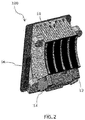
- Figure 3 shows the side view of the heat exchange system (100) according to the embodiment of the present invention.
- the figure shows the blower module (14) assembled in relation to the air channel (20).
- the blower module (14) is assembled such that maximum air is directed to the high heat regions (30) of the heat exchange system (100).
- the axis (A) of the blower module (14) is inclined towards the heat zone (30) of the heat exchange system (100).
- the high heat region (30) is formed on the base plate (16) directly behind the light source (32).
- the light source (32) and the high heat region (30) here are depicted for clarity and reference purpose and should not be taken as restricting the scope of the invention.
- the light source (32) is a monolithic LED.
- the blower module (14) blows the air through the air channel (20) and due to the profile of the air channel (20) and the arrangement of the blower module (14) maximum air is directed on the heat zone at high velocity.
- the high velocity air passing over the heat zone takes away the heat away from the heat region and out of the heat exchange system through the outlet.
- the heat transfer airfoils (10) which extend outwards from the base plate (16) also carry heat away from the high heat region through conduction.
- the air channel (20) by design as per the present invention passing through the heat transfer airfoils (10) directs air over the heat transfer airfoils. Due to the passing of the high velocity air over the heat transfer airfoils (10) heat is transferred by means of forced convection.
- the curvilinear profile and section reduction of the air channel (20) ensures high velocity air across the air channel with minimum turbulence created in the system.
- Figure 4 shows another embodiment of heat exchange system for a lighting device, of the present invention.
- the figure shows the plenum (12) attached to the heat transfer airfoils (10). Additionally, the figure shows secondary heat transfer airfoils (18) extending out of the plenum (12).
- the secondary heat transfer airfoils (18) aid in further heat transfer by means of natural convection. The arrangement increases the heat transfer rate giving more efficiency to the system.
- FIG. 5 shows the top view of the heat exchange system (100) of figure 4 , according to the embodiment of the present invention.
- the figure depicts the air channel (20) passing through the heat transfer airfoils (10).
- the secondary heat transfer airfoils (18) are also shown in the figure.
- Figure 6 shows the air flow direction for heat transfer as per the present invention.
- the embodiment as shown in figure 6 works similar to the way the embodiment of Figure 3 works.
- the current embodiment has secondary heat transfer airfoils (18) extending outwards of the plenum (12). These secondary heat transfer airfoils (18) increase the rate of heat transfer.
- the present invention can be adapted and modified to perform heat transfer in electronic system.
- the blower module (14) can be mounted on the outlet of the air channel (20).
- the blower accordingly can be modified to perform suction of air for heat transfer of the system.
- the system though effective will have lesser efficiency than the one with blower at inlet of air channel.
- the profile or the air channel can be adapted to form different profiles without deviating from the scope of present invention.
Priority Applications (2)
| Application Number | Priority Date | Filing Date | Title |
|---|---|---|---|
| EP18214707.4A EP3671023A1 (de) | 2018-12-20 | 2018-12-20 | Wärmetauscher für elektronische komponenten |
| PCT/EP2019/085471 WO2020127134A1 (en) | 2018-12-20 | 2019-12-17 | Heat exchanger for electronic components |
Applications Claiming Priority (1)
| Application Number | Priority Date | Filing Date | Title |
|---|---|---|---|
| EP18214707.4A EP3671023A1 (de) | 2018-12-20 | 2018-12-20 | Wärmetauscher für elektronische komponenten |
Publications (1)
| Publication Number | Publication Date |
|---|---|
| EP3671023A1 true EP3671023A1 (de) | 2020-06-24 |
Family
ID=64870344
Family Applications (1)
| Application Number | Title | Priority Date | Filing Date |
|---|---|---|---|
| EP18214707.4A Pending EP3671023A1 (de) | 2018-12-20 | 2018-12-20 | Wärmetauscher für elektronische komponenten |
Country Status (2)
| Country | Link |
|---|---|
| EP (1) | EP3671023A1 (de) |
| WO (1) | WO2020127134A1 (de) |
Citations (4)
| Publication number | Priority date | Publication date | Assignee | Title |
|---|---|---|---|---|
| DE102007043961A1 (de) * | 2007-09-14 | 2009-03-19 | Automotive Lighting Reutlingen Gmbh | Beleuchtungseinrichtung mit Halbleiterlichtquelle |
| DE102010002664A1 (de) * | 2010-03-08 | 2011-09-08 | Osram Gesellschaft mit beschränkter Haftung | LED-Leuchte |
| EP3043107A1 (de) * | 2015-01-09 | 2016-07-13 | Valeo Vision | Optisches modul für kraftfahrzeugscheinwerfer |
| EP3147556A1 (de) * | 2015-09-24 | 2017-03-29 | Stanley Electric Co., Ltd. | Fahrzeugbeleuchtungsvorrichtung |
-
2018
- 2018-12-20 EP EP18214707.4A patent/EP3671023A1/de active Pending
-
2019
- 2019-12-17 WO PCT/EP2019/085471 patent/WO2020127134A1/en active Application Filing
Patent Citations (4)
| Publication number | Priority date | Publication date | Assignee | Title |
|---|---|---|---|---|
| DE102007043961A1 (de) * | 2007-09-14 | 2009-03-19 | Automotive Lighting Reutlingen Gmbh | Beleuchtungseinrichtung mit Halbleiterlichtquelle |
| DE102010002664A1 (de) * | 2010-03-08 | 2011-09-08 | Osram Gesellschaft mit beschränkter Haftung | LED-Leuchte |
| EP3043107A1 (de) * | 2015-01-09 | 2016-07-13 | Valeo Vision | Optisches modul für kraftfahrzeugscheinwerfer |
| EP3147556A1 (de) * | 2015-09-24 | 2017-03-29 | Stanley Electric Co., Ltd. | Fahrzeugbeleuchtungsvorrichtung |
Also Published As
| Publication number | Publication date |
|---|---|
| WO2020127134A1 (en) | 2020-06-25 |
Similar Documents
| Publication | Publication Date | Title |
|---|---|---|
| US7329033B2 (en) | Convectively cooled headlamp assembly | |
| US7275848B2 (en) | Headlamp assembly having cooling channel | |
| US20070127257A1 (en) | Headlamp assembly with integrated housing and heat sink | |
| US10962215B2 (en) | Active radiator with omnidirectional air convection and stage lighting fixture using the same | |
| US7762696B2 (en) | Vehicle lamp | |
| CN105180049B (zh) | 用于汽车前照灯的光学模块 | |
| WO2014131269A1 (zh) | 散热器 | |
| CN110730884A (zh) | 用于热沉的系统和方法 | |
| CN109114519B (zh) | 用于机动车辆的照明模块 | |
| US20190360682A1 (en) | Lighting fixture for vehicle | |
| US20100181886A1 (en) | Heat dissipating module | |
| EP3671023A1 (de) | Wärmetauscher für elektronische komponenten | |
| JP5026901B2 (ja) | 灯具 | |
| CN217131148U (zh) | 一种提升散热效率的模组散热器结构 | |
| US20200018458A1 (en) | Lighting fixture for vehicle | |
| EP3684142A3 (de) | Induktionserwärmungsvorrichtung mit verbesserter kühlstruktur | |
| CN112739156A (zh) | 散热模块、散热器及功率设备 | |
| CN214228719U (zh) | 高效散热模组 | |
| TWI589833B (zh) | Cooling device | |
| KR102003171B1 (ko) | 강제대류 히트싱크 | |
| WO2022223745A1 (en) | Heat exchange system for an automotive lighting device | |
| JP6811600B2 (ja) | 車両用灯具の放熱構造 | |
| CN216011397U (zh) | 风冷式散热装置 | |
| CN108443845B (zh) | 一种灯具散热器 | |
| CN213208032U (zh) | 散热装置及空调器 |
Legal Events
| Date | Code | Title | Description |
|---|---|---|---|
| PUAI | Public reference made under article 153(3) epc to a published international application that has entered the european phase |
Free format text: ORIGINAL CODE: 0009012 |
|
| STAA | Information on the status of an ep patent application or granted ep patent |
Free format text: STATUS: REQUEST FOR EXAMINATION WAS MADE |
|
| 17P | Request for examination filed |
Effective date: 20181220 |
|
| AK | Designated contracting states |
Kind code of ref document: A1 Designated state(s): AL AT BE BG CH CY CZ DE DK EE ES FI FR GB GR HR HU IE IS IT LI LT LU LV MC MK MT NL NO PL PT RO RS SE SI SK SM TR |
|
| AX | Request for extension of the european patent |
Extension state: BA ME |
|
| STAA | Information on the status of an ep patent application or granted ep patent |
Free format text: STATUS: EXAMINATION IS IN PROGRESS |
|
| 17Q | First examination report despatched |
Effective date: 20221010 |
|
| P01 | Opt-out of the competence of the unified patent court (upc) registered |
Effective date: 20230528 |