EP3670780B1 - Vorrichtung zur steuerung einer aufrollbaren abdeckungsinstallation - Google Patents
Vorrichtung zur steuerung einer aufrollbaren abdeckungsinstallation Download PDFInfo
- Publication number
- EP3670780B1 EP3670780B1 EP19216902.7A EP19216902A EP3670780B1 EP 3670780 B1 EP3670780 B1 EP 3670780B1 EP 19216902 A EP19216902 A EP 19216902A EP 3670780 B1 EP3670780 B1 EP 3670780B1
- Authority
- EP
- European Patent Office
- Prior art keywords
- unit
- casing
- lighting elements
- installation
- motorization
- Prior art date
- Legal status (The legal status is an assumption and is not a legal conclusion. Google has not performed a legal analysis and makes no representation as to the accuracy of the status listed.)
- Active
Links
Images
Classifications
-
- E—FIXED CONSTRUCTIONS
- E04—BUILDING
- E04F—FINISHING WORK ON BUILDINGS, e.g. STAIRS, FLOORS
- E04F10/00—Sunshades, e.g. Florentine blinds or jalousies; Outside screens; Awnings or baldachins
- E04F10/02—Sunshades, e.g. Florentine blinds or jalousies; Outside screens; Awnings or baldachins of flexible canopy materials, e.g. canvas ; Baldachins
- E04F10/06—Sunshades, e.g. Florentine blinds or jalousies; Outside screens; Awnings or baldachins of flexible canopy materials, e.g. canvas ; Baldachins comprising a roller-blind with means for holding the end away from a building
- E04F10/0611—Sunshades, e.g. Florentine blinds or jalousies; Outside screens; Awnings or baldachins of flexible canopy materials, e.g. canvas ; Baldachins comprising a roller-blind with means for holding the end away from a building with articulated arms supporting the movable end of the blind for deployment of the blind
-
- E—FIXED CONSTRUCTIONS
- E04—BUILDING
- E04F—FINISHING WORK ON BUILDINGS, e.g. STAIRS, FLOORS
- E04F10/00—Sunshades, e.g. Florentine blinds or jalousies; Outside screens; Awnings or baldachins
- E04F10/02—Sunshades, e.g. Florentine blinds or jalousies; Outside screens; Awnings or baldachins of flexible canopy materials, e.g. canvas ; Baldachins
- E04F10/06—Sunshades, e.g. Florentine blinds or jalousies; Outside screens; Awnings or baldachins of flexible canopy materials, e.g. canvas ; Baldachins comprising a roller-blind with means for holding the end away from a building
- E04F10/0644—Sunshades, e.g. Florentine blinds or jalousies; Outside screens; Awnings or baldachins of flexible canopy materials, e.g. canvas ; Baldachins comprising a roller-blind with means for holding the end away from a building with mechanisms for unrolling or balancing the blind
- E04F10/0659—Control systems therefor
-
- E—FIXED CONSTRUCTIONS
- E06—DOORS, WINDOWS, SHUTTERS, OR ROLLER BLINDS IN GENERAL; LADDERS
- E06B—FIXED OR MOVABLE CLOSURES FOR OPENINGS IN BUILDINGS, VEHICLES, FENCES OR LIKE ENCLOSURES IN GENERAL, e.g. DOORS, WINDOWS, BLINDS, GATES
- E06B9/00—Screening or protective devices for wall or similar openings, with or without operating or securing mechanisms; Closures of similar construction
- E06B9/56—Operating, guiding or securing devices or arrangements for roll-type closures; Spring drums; Tape drums; Counterweighting arrangements therefor
- E06B9/68—Operating devices or mechanisms, e.g. with electric drive
- E06B9/72—Operating devices or mechanisms, e.g. with electric drive comprising an electric motor positioned inside the roller
-
- F—MECHANICAL ENGINEERING; LIGHTING; HEATING; WEAPONS; BLASTING
- F21—LIGHTING
- F21V—FUNCTIONAL FEATURES OR DETAILS OF LIGHTING DEVICES OR SYSTEMS THEREOF; STRUCTURAL COMBINATIONS OF LIGHTING DEVICES WITH OTHER ARTICLES, NOT OTHERWISE PROVIDED FOR
- F21V33/00—Structural combinations of lighting devices with other articles, not otherwise provided for
- F21V33/006—General building constructions or finishing work for buildings, e.g. roofs, gutters, stairs or floors; Garden equipment; Sunshades or parasols
-
- H—ELECTRICITY
- H05—ELECTRIC TECHNIQUES NOT OTHERWISE PROVIDED FOR
- H05B—ELECTRIC HEATING; ELECTRIC LIGHT SOURCES NOT OTHERWISE PROVIDED FOR; CIRCUIT ARRANGEMENTS FOR ELECTRIC LIGHT SOURCES, IN GENERAL
- H05B47/00—Circuit arrangements for operating light sources in general, i.e. where the type of light source is not relevant
- H05B47/10—Controlling the light source
- H05B47/105—Controlling the light source in response to determined parameters
-
- E—FIXED CONSTRUCTIONS
- E06—DOORS, WINDOWS, SHUTTERS, OR ROLLER BLINDS IN GENERAL; LADDERS
- E06B—FIXED OR MOVABLE CLOSURES FOR OPENINGS IN BUILDINGS, VEHICLES, FENCES OR LIKE ENCLOSURES IN GENERAL, e.g. DOORS, WINDOWS, BLINDS, GATES
- E06B9/00—Screening or protective devices for wall or similar openings, with or without operating or securing mechanisms; Closures of similar construction
- E06B9/56—Operating, guiding or securing devices or arrangements for roll-type closures; Spring drums; Tape drums; Counterweighting arrangements therefor
- E06B9/68—Operating devices or mechanisms, e.g. with electric drive
- E06B2009/6809—Control
- E06B2009/6818—Control using sensors
-
- F—MECHANICAL ENGINEERING; LIGHTING; HEATING; WEAPONS; BLASTING
- F21—LIGHTING
- F21Y—INDEXING SCHEME ASSOCIATED WITH SUBCLASSES F21K, F21L, F21S and F21V, RELATING TO THE FORM OR THE KIND OF THE LIGHT SOURCES OR OF THE COLOUR OF THE LIGHT EMITTED
- F21Y2115/00—Light-generating elements of semiconductor light sources
- F21Y2115/10—Light-emitting diodes [LED]
Definitions
- the present invention relates to an improved device for controlling a roll-up roof installation, preferably of a motorized roller blind.
- Rolling curtains of the type comprising a sheet which, in the condition of a retracted curtain, is wound on a tubular shaft and in the unfolded curtain condition is unwound from said shaft and is kept extended by its constraint with one side to said tubular shaft and with the opposite side to a rigid crosspiece that can be approached and moved away from the tubular shaft itself.
- the tubular shaft is supported at both ends in a traditional manner by the fixed external structure.
- the rigid crosspiece In the case of a protruding curtain, the rigid crosspiece is connected to the support structure of the tubular shaft through a pair of articulated arms, while in the case of sliding curtain the rigid crosspiece is made to slide with ends along two fixed parallel guides placed on the sides of the surface that must be able to be covered by the unfolded curtain.
- the rigid crosspiece may have a conformation such as to cover the awning, when it is wrapped around the tubular shaft, and in this way to constitute a sort of protective box thereof, which in this case is called a boxed tent.
- the motor is controlled by a control unit which is generally positioned externally with respect to the tubular shaft and the tent structure and, in particular, is housed within a casing fixed to the fixed external structure.
- the current market requirement is to equip the curtains with lights that can be used to illuminate the surface below the curtain and/or to create courtesy lights and/or to create lighting effects, in particular RGB effects.
- this requirement is satisfied in the articulated arm awnings by applying these lights, preferably LED lights, to the arms themselves and/or to the rigid crosspiece and/or to the support structure of the curtain, and in the sliding curtains by applying these lights to the guides and/or to the uprights supporting the guides and/or to the other parts of the tent supporting structure.
- Tubular motors have also been proposed provided with an output for powering the lights and therefore motors in which the light supply unit is integrated in the motor itself.
- EP2199484 already describes a solution in which the motor and the lights are controlled and also powered by the same control unit, which is connected to a current-voltage power source.
- the object of the invention is to propose a device for controlling a roll-up roof installation, in particular a roller blind, which eliminates the drawbacks encountered in traditional solutions.
- Another object of the invention is to propose a device that optimally combines the motorization functionality of the roll-up cover with that for lighting the underlying area and/or around said covering, or for creating lighting effects.
- Another object of the invention is to propose a device that can be easily installed even by unskilled personnel.
- Another object of the invention is to propose a device that is easy to program and manage.
- Another object of the invention is to propose a device that is independent, autonomous and/or additional with respect to the motorization unit of the roll-up roof installation.
- Another object of the invention is to propose a device that is perfectly in line with the safety requirements imposed by the legislation of the sector.
- Another object of the invention is to propose a device that allows greater integration of the components.
- Another object of the invention is to propose a device that allows the installation of a roll-up cover, in particular of a roller blind, even in places where mounting of the control unit to the external support structure is not possible or is difficult.
- Another object of the invention is to propose a device that can be remotely controlled even from a mobile phone.
- Another object of the invention is to propose a device which is both improved and/or alternative to the traditional ones.
- Another object of the invention is to propose a device which entails low installation costs.
- Another object of the invention is to propose a device that can be obtained in a simple, rapid manner and with low costs.
- Another object of the invention is to propose a roll-up covering installation, in particular a sectional roller blind, which is provided with a control device which is simple to install, easy to program and to manage, and obtainable in a simple, rapid manner. with low costs.
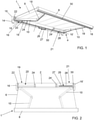
- control device according to the invention is applied/mounted, in the example shown, to a roll-up roof installation, in particular a roller blind, indicated as a whole with the reference number 1.
- the roller blind 1 is of the traditional type.
- the roller blind 1 is motorized but could also be moved manually.
- the roller blind 1 is of the type with articulated arms, i.e. it is of the type which comprises a tubular shaft 2, a support structure 4 of the tubular shaft 2, a sheet 6 which can be wound around the tubular shaft 2 and unwound by this and a supporting structure of said sheet 6.
- the supporting structure of said sheet 6 comprises a rigid cross-piece 8, to which is applied the edge of the sheet 6 opposite to that bound to the tubular shaft 2, and two pairs of articulated arms 10, which connect the rigid crosspiece 8 to the support structure 4 and guide it in its translational movements with respect to it.
- the winding/unwinding of the sheet 6 can take place both along a substantially vertical direction, and along a more or less inclined direction with respect to the vertical.
- the tubular shaft 2 can be for example a metal shaft which, suitably, can have any cross-section.
- the tubular shaft 2 can have a circular or polygonal section, for example hexagonal, octagonal or similar.
- the tubular shaft 2 is of the type traditionally usable for curtains and/or for rolling shutters.
- the support structure 4 can comprise:
- the sheet 6 can be of any traditional type and does not require further explanation.
- the rigid crosspiece 8 can be constituted by a piece of metal or plastic profile and can have any section.
- the rigid crosspiece 8 is shaped so that when the curtain is in a wound condition, it adheres to the support structure 4 and forms with it a sort of container or "box", which houses inside it the tubular shaft 2, the sheet 6 wound on it and the articulated arms 10, which are in the folded condition.
- lighting elements 18 are mounted on the roller blind 1.
- the lighting elements 18 can be mounted on any component of the roller blind 1 and in any position thereof. More particularly, the lighting elements 18 can be mounted on the support structure 4 and/or on the articulated arms 10 and/or on the rigid crosspiece 8 and/or on the tubular shaft 2 and/or also on the sheet 6.
- the lighting elements 18 are to be mounted on the rigid elements of the roller blind 1, such as the support structure 4 and/or the articulated arms 10 and/or the tubular shaft 2 and/or the rigid crosspiece 8
- the lighting elements 18 are connected - preferably by means of cables/wires connecting to an electrical connection - to the control device 26 housed in the tubular shaft 2.
- the electrically connecting conductor cables run inside the components of the roller blind 1 and, therefore, they are hidden from view from the outside.
- the lighting elements 18 are light sources and, preferably, are strips of LEDs that define monochromatic and/or RGB light sources.
- the lighting elements are supplied with direct current, for example at 12V, 24V, 36V or 48V.
- the lighting elements 18 consist of at least one strip of LEDs which comprises a set of LED diodes, i.e. electronic components which emit light when supplied with electricity.
- the LED diodes are fixed - preferably by welding - on a printed circuit (PCB), preferably flexible, which performs the function of support and electrical connection.
- the LED diodes of the LED strip can be configured to emit monochromatic light or can be of the RGB type.
- strips of LED 18 which globally form diffuse sources of monochromatic light or RGB light and are connected to the control device 26 housed in the tubular shaft 2 by means of electrical connecting conducting cables running inside the rigid crosspiece 8 and the articulated arms 10, and/or the other rigid components of the roller blind 1.
- the roller blind 1 comprises means configured to cause rotation in the two directions of the tubular shaft 2, thus allowing to cover and unwind the covering sheet 6 having a flap fixed to said shaft.
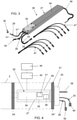
- a motorization unit 20 is inserted in the tubular shaft 2 to cause rotation of the shaft itself in both directions.
- this motorization unit 20 is inserted into the tubular shaft 2 at a first end 19 thereof.
- the motorization unit 20 comprises at least one electric drive/drive motor inserted within the tubular shaft itself.
- said at least one electric motor is tubular.
- the motorization unit 20 can comprise one or two electric motors in direct current.
- the motorization unit 20 can comprise one or two electric motors in alternating current.
- the motorization unit 20 can comprise an electric motor in direct current and an electric motor in alternating current.
- said direct current electric motors are fed for example with direct current at 12V, 24V, 36V or 48V.
- said or said electric motors in alternating current are of the single-phase asynchronous type.
- the motorization unit 20 is provided with a head 22 which is suitably fixed with any known system to the support structure 4, preferably it is fixed to the wing bracket 16 of the latter.
- the motorization unit 20 is also provided with an output pinion to which an adapter 24 (pulley) for towing the tubular shaft 2 is coupled, cooperating in a conventional manner with an analogous, un towed adapter which is mounted in the vicinity of said head 22.
- means can be provided - which can be manually operated and actuated - configured to cause rotation in both directions of the tubular shaft 2.
- these means are configured to cause rotation in both directions of the tubular shaft 2 can be constituted by a traditional winch that can be operated manually or with an electric motor applied to it.
- the device 26 for controlling the motorization unit 20 and/or the lighting elements 18 comprises a casing 27 which, advantageously, has a box-like shape and is preferably long and narrow.
- the casing 27 has a base with dimensions of a few centimetres (for example of about 2.5 cm x 3 cm) and a longitudinal extension much greater than about 10 cm, for example is about 60 cm.
- control device 26 is substantially independent and autonomous from a constructive and positioning point of view both with respect to the motorization unit 20 of the roll-up cover installation and with respect to the lighting elements 18.
- the casing 27 of the device 26 thus shaped can potentially be associated externally with any rigid element of the roller blind 1, such as the support structure 4 and/or the articulated arms 10 and/or the tubular shaft 2 and/or the rigid crosspiece 8, or it can be fixed to the fixed external structure to which the roller blind 1 is applied, or it can be fixed in an adjacent area with respect to said roller blind 1 or to said fixed external structure.
- the casing 27 of the device 26 thus shaped can be potentially inserted and housed inside a support bar 50 with a square or rectangular section (see fig. 1 ) which is fixed to the fixed external structure to which the roller blind is applied.
- the casing 27 of the device 26 thus shaped can be potentially inserted and housed alone inside any rigid element of the roller blind 1, such as the support structure 4 and/or the articulated arms 10 and/or the tubular shaft 2 and/or the rigid crosspiece 8.
- the casing 27 of the device 26 can be inserted inside a second casing 28 (see fig. 2 and 4 ), preferably tubular, which is removably inserted inside of the tubular shaft 2 or in any rigid element of the roller blind 1, such as the support structure 4 and/or the articulated arms 10 and/or the rigid crosspiece 8.
- a second casing 28 preferably tubular, which is removably inserted inside of the tubular shaft 2 or in any rigid element of the roller blind 1, such as the support structure 4 and/or the articulated arms 10 and/or the rigid crosspiece 8.
- the shape of the casing 27 is not connected to that of the second casing 28 although obviously having to be compatible with this.
- the casing 27 has a shape and dimensions suitable for allowing its insertion and housing inside the second casing 28.
- the stability of the positioning of the casing 27 inside the second casing 28 is obtained by means of suitable adapters (not represented).
- the casing 27 is inserted, preferably inside the second casing 28, at the other end 21 of the tubular shaft 2.
- the motor motorization unit 20 of the shaft itself at the other end 21 of the tubular shaft 2 can be inserted and housed the control device 26 of the lighting elements 18 mounted on at least one component of the roll-up cover installation 1.
- the means for fixing the second casing 28 to said external support structure comprise a head 30 which is applied to said second casing 28 so as to fix it to the other wing bracket 16' of the support structure 4.
- the head 30 integrates the second casing 28 to the fixed external support structure, thus supporting the tubular shaft 2 at its end 21.
- said means which are interposed between said second casing 28 and the tubular shaft 2 comprise adapters 24' , 24" configured to allow the second casing 28 to idly support the tubular shaft 2.
- the adapters 24', 24" are positioned around the second casing 28 and rotate, together with the tubular shaft 2, around said casing, which instead remains fixed (i.e. does not rotate).
- a pair of support adapters 24' and 24" are provided which are interposed between the opposite sides of the second casing 28 and the tubular shaft 2.
- an adapter 24' is provided on the inner side of the second casing 28 and an adapter 24" on the external side of said casing.
- both the head 30 and the adapters 24', 24" have a shape similar to that of the head 22 and the adapters of the motorization unit 20, respectively, but unlike the latter they have the sole function of idle support of the tubular shaft 2 at its end 21 which is opposite to the insertion end 19 of said motorization unit 20.
- the second casing 28 supports the tubular shaft 2 at the end 21 of the latter, end which is opposite to the one (end 19) in which the motorization unit 20 is inserted. Furthermore, appropriately, the second casing 28 is fixed by the head 30 to the fixed external support structure and, therefore, supports the tubular shaft 2 without rotating with the latter, which is in fact set in rotation, by the motorization unit 20, around an axis that crosses it longitudinally.
- the shape and the dimensions of the second casing 28 are not linked to those of the tubular shaft 2 although obviously they must be compatible with those.
- the second casing 28 has a shape and dimensions suitable for allowing its insertion and housing inside the tubular shaft 2.
- the stability of the positioning of the second casing 28 inside the tubular shaft 2 is obtained by means of the adapters 24' and 24".
- control device 26 comprises a power supply unit 34, a control unit 35 and a receiver 36 which is connected or incorporated in said unit.
- the power supply 34 which is configured to supply at the output the electric power supply suitable for the motorization unit and/or for the lighting elements 18.
- the power supply 34 housed in the casing 27 can receive in input the electric power supply from the outside, preferably it is fed directly through a cable 38 connected to an external electric source (not shown), preferably it is connected to the network.
- the power supply 34 housed in the casing 27 may receive in input the electric power supply from one or more batteries 42 which, preferably, can be recharged with one or more external photovoltaic panels 44 which, suitably, can be mounted on the roller blind 1 and/or can be external and independent from the latter.
- the rechargeable battery 42 can advantageously be housed inside the casing 27 or the second casing 28.
- a first door can be provided to access the external to the inside of the casing itself, for example in order to access - if provided - the rechargeable battery 42.
- a second door may also be provided in the tubular shaft 2 to access the first door formed in the casing.
- the first door of the casing 27 or of the second casing 28 and the second door of the tubular shaft 2 face each other. Obviously, this accessibility requires that the device 26 is correctly inserted into the tubular shaft 2 and that the curtain is unfolded, i.e. that the sheet 6 is unwound from the tubular shaft 2 and does not cover the second the flap.
- the same rechargeable battery 42 can also supply the motorization unit 20, preferably by means of an inverter, also housed inside the casing 27 or the second casing 28.
- the entire roller blind 1 can be also installed in places where mains power is not available.
- the motorization unit 20 can be supplied through an external low voltage supply, again by means of an inverter.
- the power supply 34 comprises a transformer 37 configured to provide at its output a power lower than or equal to about 240W and which, suitably, is substantially sufficient to supply either only the motorization unit 20 or only the lighting elements 18.
- the transformer 37 is configured to provide a power output of about 60W-240W, preferably of about 150W-240W.
- control unit 35 for example a processor of the motorization unit 20 and/or of the lighting elements 18.
- control unit 35 is electrically connected with the power supply 34 and, preferably, the output of the power supply 34 is connected to the input of the control unit 35.
- control device 26 also comprises means which electrically connect the control unit 35 (housed in the casing 27) with the motorization unit 20 externally with respect to the tubular winding shaft 2, i.e. it does not cross the shaft internally and longitudinally.
- control unit 35 is connected to the motors of the motorization unit 20 by means of first wiring 29 which protrudes from the casing 27.
- the first wiring 29 comprises conducting cables for connecting and transmitting electrical signals.
- the wiring 29 comprise a first cable 31' for connection to a direct current electric motor of the motor motorization unit 20 and a second cable 31" for connection to an electric motor in alternating current of the motor motorization unit 20.
- the electrical connections between the control device 26 and the motorization unit 20 are external to the tubular shaft 2 and are advantageously carried out at the place of production, so that this may leave a finished product.
- control unit 35 (housed in the casing 27) is connected by means of the first wiring 29 with a first output interface 30 provided outside the casing 27 (and of the possible second casing 28) and, suitably , said first interface 30 is in turn connected by means of a suitable wiring (not shown), which runs externally with respect to the tubular shaft 2, to the motors of the motorization unit 20 which is positioned inside the tubular shaft 2 at the first end 19.
- the command/communication drivers are implemented in the control unit 35 with said first output interface 30 connected to the motors of the motorization unit 20.
- control device 26 comprises also means which electrically connect the control unit 35 (housed in the casing 28) with the lighting elements 18.
- the control unit 35 is connected to the lighting elements 18 by means of second wiring 33 which protrude from the casing 27 and, advantageously, run inside the rigid elements of the covering installation 1.
- the second wiring 33 comprises conductor cables 39 for connecting and transmitting signals electric.
- the control unit 35 housed in the casing 27 is also connected, by means of the second wiring 33, to a second output interface 40 which is provided outside of the casing 27 (and of the possible second casing 28) and which in turn is connected to the lighting elements 18 by means of suitable conducting cables 47 which, advantageously, run inside the rigid elements of the covering installation 1.
- control unit 35 are implemented the control/communication drivers with the output interface 40 connected to the lighting elements 18.
- control unit 35 housed in the casing 27 can also be connected to further output interfaces (not shown), in turn connected - by means of suitable wiring external to the tubular shaft 2 - to external elements (safety devices, wired controls, possible acoustic diffusion system).
- the receiver 36 is also provided inside the casing 27 and is connected, preferably via wireless and/or wire, to the outside of said roller blind 1 to receive control signals from the outside to control, based on these, said motorization unit 20 and said lighting elements 18.
- the receiver 36 is of the wireless type, preferably radio.
- the control unit 35 can receive from an external transmitter, and in particular from a remote control or even from a mobile telephone (preferably a smartphone) or from other traditional wireless devices in general, control signals for the motorization unit 20 and lighting elements 18.
- the receiver 36 is connected and/or incorporated to the electronic circuit of the control unit 35 to be operatively connected to the control/communication drivers of the first output interface 30 connected to the motorization unit 20 and the second output interface 40 connected to the lighting elements 18.
- the receiver can be connected to a centralized or distributed automated home, and to send it, preferably via Wi-Fi and via the Internet protocol, to an external portable device, or to a cloud storage accessible from the external portable device, in addition to monitoring its operation.
- the connection between the receiver 36 and the home automation unit can take place via cable or wireless, in particular by radio waves (for example wi-fi or according to the Bluetooth protocol).
- the receiver 36 can be connected, via wireless and/or by wire, to light, wind and/or rain sensors.
- the control unit 35 is configured so that, if and when an activation command of the motorization unit 20 is received while the lighting elements 18 are powered, the electrical energy for supplying the lighting elements 18 is automatically reduced, thus also reducing the brightness generated by these elements. Conveniently, the reduction of electrical energy for supplying the lighting elements 18 thus allows the use of all the power of the transformer 37 of the power supply 34 for the current source of the motorization unit 20.
- control unit 35 is configured in such a way that, in a condition in which the lighting elements 18 are already supplied, the receipt of an activation command for the motorization unit 20 automatically causes the reduction of the electric power supply of said lighting elements 18, and then reducing the brightness generated by these.
- the reduction of the electric power supply of the lighting elements 18 which occurs upon receipt of the activation command for the motorization unit 20 is such as to reach a minimum value of electric power supply for said lighting elements 18.
- this reduction in the electric power supply of the lighting elements 18 is preset and, preferably, can be defined during the installation by the installer, acting through an external transmitter, in particular by means of a smartphone-type mobile telephone, as described more in detail below.
- this reduction in the electric power supply of the lighting elements 18 which occurs upon receipt of the activation command for the motorization unit 20 is automatically defined by suitable algorithms which are implemented inside the control unit 35 and which advantageously, also take into consideration the external environmental conditions in which the aforementioned activation command was received.
- this activation command is received by the control unit 35 through the receiver 36.
- this activation command can be a command signal sent by an external transmitter, and in particular by a remote control or even a mobile telephone, preferably a smartphone, or from other traditional wireless devices in general.
- this activation command can be a command signal sent by an external sensor, in particular by a light, wind and/or rain sensor.
- control unit 35 is configured so that, in a condition in which the lighting elements 18 are already supplied, the reception of an activation command for the motorization unit 20 automatically causes:
- the electric power which the control unit 35 sends to the lighting elements 18 is reduced, so that at the output of the power supply 34 there is sufficient electricity to be sent to the motorization unit 20 for its activation/supply.
- a portion of the electric power used to power the lighting elements 18 is diverted to the motorization unit 20 so as to have sufficient power to enable it to be activated.
- the receiver 36 can advantageously be replaced by a transceiver, preferably radio, which in addition to sending corresponding command signals to the motorization unit 20 and to the lighting elements 18 can remotely communicate their status and, preferably, also the operating parameters or any anomalies or malfunctions.
- a transceiver preferably radio
- the receiver side - in addition to controlling/communicating - by means of its receiver side - with the first output interface 30 connected to the motorization unit 20 and with the second output interface 40 connected to the lighting elements 18 , can transmit - with its transmitter side - signals on the state of said motorization unit 20 and/or of said lighting elements 18.
- the user can remotely control, for example by means of a mobile phone (preferably a smartphone), the switching on and off and adjustment of the lighting elements 18 and of the motorization unit 20 and can receive, again with the mobile phone (preferably a smartphone), information on their current status.
- the transceiver is connected and/or incorporated to the electronic circuit of the control unit 35 to be operatively connected to the control/communication drivers of the first output interface 30 connected to the motorization unit 20 and the second output interface 40 connected to the lighting elements 18.
- a software module is loaded and executed in said device - which preferably consists of a native mobile software application, also known as APP - configured to connect wireless with the receiver 36 for managing and setting the control unit 35 as well as for controlling the switching on and off and adjustment of the motorization unit 20 or lighting elements 18.
- APP native mobile software application
- the software module is configured to allow the user to set the reduction in the control unit 35 of the brightness of the lighting elements 18, and therefore of the electrical energy required for their supply, which is carried out automatically by said control unit 35 (when said lighting elements 18 are already supplied) following the reception of a command for the activation of the motorization unit 20.
Landscapes
- Engineering & Computer Science (AREA)
- Architecture (AREA)
- Structural Engineering (AREA)
- Civil Engineering (AREA)
- General Engineering & Computer Science (AREA)
- Operating, Guiding And Securing Of Roll- Type Closing Members (AREA)
- Lifting Devices For Agricultural Implements (AREA)
- Centrifugal Separators (AREA)
- Rear-View Mirror Devices That Are Mounted On The Exterior Of The Vehicle (AREA)
- Spinning Or Twisting Of Yarns (AREA)
- Indicating And Signalling Devices For Elevators (AREA)
- Jib Cranes (AREA)
Claims (15)
- Vorrichtung (26) zum Steuern sowohl der Motorisierungseinheit (20) einer aufrollbaren Abdeckungsinstallation (1) als auch einer Vielzahl von Leuchtelementen (18), die an mindestens einer Komponente (2,4,6,8,10) der aufrollbaren Abdeckungsinstallation (1) angebracht sind, wobei die Vorrichtung (26) ein Gehäuse (27) umfasst, das in eine Komponente der Installation (1) oder der Stützstruktur eingesetzt werden kann und/oder außerhalb der Installation (1) oder deren Stützstruktur oder in deren Nähe verbunden werden kann, wobei innerhalb des Gehäuses (27) angeordnet und untergebracht sind:- mindestens eine Stromversorgungseinheit (34) für die Motorisierungseinheit (20) und für die Leuchtelemente (18),- mindestens eine Einheit (35) zum Überwachen und Steuern, die mit der Motorisierungseinheit (20) und den Leuchtelementen (18) der aufrollbaren Abdeckungsinstallation (1) verbindbar ist,- ein Empfänger oder Transceiver (36), der mit der Steuer- und Befehlseinheit (35) verbunden und/oder darin integriert ist, um von außen Steuersignale zum Steuern, basierend darauf, der Motorisierungseinheit (20) und der Leuchtelemente (18) zu empfangen,dadurch gekennzeichnet, dass die Steuereinheit (35) derart ausgelegt ist, dass, wenn ein Aktivierungsbefehl der Motorisierungseinheit (20) empfangen wird, während die Leuchtelemente (18) versorgt werden, die Leistung für die Versorgung der Leuchtelemente (18) automatisch reduziert wird, wodurch auch die durch diese Elemente erzeugte Helligkeit reduziert wird, um zur Versorgung der Motorisierungseinheit (20) verwendet zu werden.
- Vorrichtung nach Anspruch 1, dadurch gekennzeichnet, dass die Steuereinheit (35) derart ausgelegt ist, dass, wenn die Leuchtelemente (18) bereits versorgt werden, der Empfang eines Aktivierungsbefehls für die Motorisierungseinheit (20) automatisch erzeugt:- zuerst die Reduzierung der Stromversorgung der Leuchtelemente (18) und- nachfolgend das Starten der Stromversorgung der Motorisierungseinheit (20),und dadurch, dass die elektrische Energie zum Versorgen der Leuchtelemente (18) automatisch reduziert wird, um ausreichend elektrische Energie für die Stromversorgung und/oder Aktivierung der Motorisierungseinheit (20) aufzuweisen.
- Vorrichtung nach einem der vorstehenden Ansprüche, dadurch gekennzeichnet, dass der Aktivierungsbefehl der Motorisierungseinheit (20) durch die Steuereinheit (35) über den Empfänger oder Transceiver (36) empfangen wird und ein von einem externen Sender gesendetes Befehlssignal ist.
- Vorrichtung nach einem der vorstehenden Ansprüche, dadurch gekennzeichnet, dass der Aktivierungsbefehl der Motorisierungseinheit (20) durch die Steuereinheit (35) empfangen wird und ein durch einen externen Sensor, insbesondere von einem Licht-, Wind- und/oder Regensensor, gesendetes Befehlssignal ist.
- Vorrichtung nach einem der vorstehenden Ansprüche, dadurch gekennzeichnet, dass, in der Steuereinheit (35), die Reduzierung der Stromversorgung der Leuchtelemente (18) mittels eines dedizierten Softwaremoduls (APP), das in einer externen tragbaren Vorrichtung geladen und ausgeführt wird, festgelegt wird.
- Vorrichtung nach einem der vorstehenden Ansprüche, dadurch gekennzeichnet, dass das Gehäuse von einer länglichen kastenartigen Form ist, um innerhalb einer Komponente der Abdeckungsinstallation (1) oder von deren Stützstruktur eingesetzt oder untergebracht zu werden.
- Vorrichtung nach einem der vorstehenden Ansprüche, dadurch gekennzeichnet, dass sie umfasst:- mindestens eine erste Verdrahtung (29), die mit der Steuer- und Befehlseinheit (35) verbunden ist und vom Gehäuse vorsteht, um mit der Motorisierungseinheit (20) verbunden zu werden,- mindestens eine zweite Verdrahtung (39), die mit der Steuer- und Befehlseinheit (35) verbunden ist und die vom Gehäuse vorsteht, um mit den Leuchtelementen (18) verbunden zu werden.
- Vorrichtung nach einem der vorstehenden Ansprüche, dadurch gekennzeichnet, dass das Gehäuse (27) innerhalb eines zweiten Gehäuses (28) untergebracht ist, das dazu ausgelegt ist, entfernbar und vollständig innerhalb und in Übereinstimmung mit einem Ende einer Rohrwelle (2) der aufrollbaren Abdeckungsinstallation (1), die durch die Motorisierungseinheit (20) gedreht wird und um die die Abdeckung der Installation gewickelt wird, eingesetzt und untergebracht zu werden, wobei die Vorrichtung außerdem dadurch gekennzeichnet ist, dass sie umfasst:- einen Kopf (30), der an der Außenseite des zweiten Gehäuses (28) angebracht ist, um es an der externen Stützstruktur (4) zu befestigen, und/oder- mindestens einen Adapter (24'), der zwischen dem zweiten Gehäuse (28) und der Rohrwelle (2) eingeschoben ist und der dazu ausgelegt ist, sich mit der Rohrwelle (2) zu drehen und es dem zweiten Gehäuse (28) zu ermöglichen, die Rohrwelle (2) ruhend zu stützen.
- Vorrichtung nach einem der vorstehenden Ansprüche, dadurch gekennzeichnet, dass die in dem Rohrgehäuse (27) untergebrachte Stromversorgungseinheit (34) von außen durch ein Kabel (38) gespeist wird, das aus dem Gehäuse (27) austritt, um mit einer externen Stromquelle verbunden zu werden.
- Vorrichtung nach einem der vorstehenden Ansprüche, dadurch gekennzeichnet, dass der Empfänger oder Transceiver (36) vom drahtlosen Typ, vorzugsweise Funk, ist.
- Vorrichtung nach einem der vorstehenden Ansprüche, dadurch gekennzeichnet, dass die Stromversorgungseinheit (34) einen Transformator (37) umfasst, der dazu ausgelegt ist, eine Leistungsabgabe, vorzugsweise kleiner oder gleich etwa 240 W, was im Wesentlichen zur Versorgung entweder der Motorisierungseinheit (20) oder der Leuchtelemente (18) ausreichend ist, bereitzustellen.
- Aufrollbare Abdeckungsinstallation (1) des Typs, umfassend:- eine Stützstruktur (4) zum Halten der Abdeckungsinstallation (1) an einer festen externen Struktur,- eine Rohrwelle (2), die durch die Struktur (4) gestützt wird,- eine Motorisierungseinheit (20) zum Bewirken der Drehung der Rohrwelle (2), wobei die Motorisierungseinheit (20) innerhalb der Rohrwelle (2) der Installation an einem Ende (19) der Welle (2) eingesetzt und untergebracht ist,- eine Abdeckung (6), die auf die Rohrwelle (2) gewickelt und durch diese getragen werden soll,- eine Tragstruktur (8, 10) der Abdeckung (6),- eine Vielzahl von Leuchtelementen (18), die an mindestens einer Komponente (2,4,6,8,10) der aufrollbaren Abdeckungsinstallation (1) angebracht sind,dadurch gekennzeichnet, dass die aufrollbare Abdeckungsinstallation (1) ferner eine Vorrichtung (26) nach einem der vorstehenden Ansprüche umfasst, wobei das Gehäuse (27) der Vorrichtung (26) innerhalb einer Komponente der Installation (1) oder von deren Stützstruktur eingesetzt ist und/oder direkt mit der Installation (1) oder mit deren Stützstruktur oder in deren Nähe verbunden ist, wobei die Steuereinheit (35) der Vorrichtung (26) elektrisch mit der Motorisierungseinheit (20) und mit den Leuchtelementen (18) verbunden ist.
- Installation nach dem vorstehenden Anspruch, dadurch gekennzeichnet, dass die Motorisierungseinheit (20) umfasst:- mindestens einen Gleichstromelektromotor oder- mindestens einen Wechselstromelektromotor oder- einen Gleichstromelektromotor und einen Wechselstromelektromotor.
- Installation nach Anspruch 12 oder 13, dadurch gekennzeichnet, dass die Vorrichtung (26) innerhalb der Rohrwelle an einem gegenüberliegenden Ende in Bezug auf das, in dem die Motorisierungseinheit (20) eingesetzt und untergebracht ist, eingesetzt ist.
- Installation nach Anspruch 12, 13 oder 14, dadurch gekennzeichnet, dass die in dem Gehäuse (27) der Vorrichtung (26) untergebrachte Stromversorgung (34) dazu ausgelegt ist, als Eingang die Stromversorgung von mindestens einer Batterie (42) zu empfangen, die vorzugsweise mit mindestens einem externen Photovoltaikpanel (44) wiederaufgeladen werden kann.
Priority Applications (1)
| Application Number | Priority Date | Filing Date | Title |
|---|---|---|---|
| PL19216902T PL3670780T3 (pl) | 2018-12-20 | 2019-12-17 | Urządzenie do sterowania instalacją rozwijanej osłony |
Applications Claiming Priority (1)
| Application Number | Priority Date | Filing Date | Title |
|---|---|---|---|
| IT102018000020488A IT201800020488A1 (it) | 2018-12-20 | 2018-12-20 | Dispositivo perfezionato per il controllo di una installazione di copertura avvolgibile |
Publications (2)
| Publication Number | Publication Date |
|---|---|
| EP3670780A1 EP3670780A1 (de) | 2020-06-24 |
| EP3670780B1 true EP3670780B1 (de) | 2022-03-23 |
Family
ID=66218300
Family Applications (1)
| Application Number | Title | Priority Date | Filing Date |
|---|---|---|---|
| EP19216902.7A Active EP3670780B1 (de) | 2018-12-20 | 2019-12-17 | Vorrichtung zur steuerung einer aufrollbaren abdeckungsinstallation |
Country Status (5)
| Country | Link |
|---|---|
| EP (1) | EP3670780B1 (de) |
| ES (1) | ES2917648T3 (de) |
| IT (1) | IT201800020488A1 (de) |
| PL (1) | PL3670780T3 (de) |
| PT (1) | PT3670780T (de) |
Families Citing this family (3)
| Publication number | Priority date | Publication date | Assignee | Title |
|---|---|---|---|---|
| CN113186935B (zh) * | 2021-05-31 | 2024-07-23 | 中国五冶集团有限公司 | 一种集成照明喷淋的防尘幕布结构 |
| CN113245335B (zh) * | 2021-06-11 | 2024-07-19 | 中国五冶集团有限公司 | 一种大跨度基坑施工智能双向牵引降尘幕网系统 |
| IT202300019773A1 (it) * | 2023-09-26 | 2025-03-26 | Nice Spa | Sistema per la movimentazione di almeno un elemento ombreggiante e metodo per la selezione ed il controllo di un attuatore elettromeccanico di tale sistema |
Family Cites Families (7)
| Publication number | Priority date | Publication date | Assignee | Title |
|---|---|---|---|---|
| NL1007549C2 (nl) * | 1997-11-14 | 1999-05-17 | Creal Handelsondernemingen Bes | Zonwering met verlichting. |
| DE102008063766A1 (de) * | 2008-12-22 | 2010-07-01 | Weinor Gmbh & Co. Kg | Markise |
| AU2014200269C1 (en) | 2010-02-23 | 2020-02-27 | The Watt Stopper, Inc. | High efficiency roller shade |
| DE102012003350A1 (de) * | 2012-02-21 | 2013-08-22 | Weinor Gmbh & Co. Kg | Markise mit Beleuchtungseinrichtung |
| US9169690B2 (en) * | 2013-03-14 | 2015-10-27 | Lutron Electronics Co., Inc. | Window treatment having backlighting |
| US9267327B2 (en) | 2014-06-17 | 2016-02-23 | Crestron Electronics Inc. | Shading control network using a control network |
| US9644424B2 (en) | 2015-10-12 | 2017-05-09 | Crestron Electronics, Inc. | Touch hem bar control |
-
2018
- 2018-12-20 IT IT102018000020488A patent/IT201800020488A1/it unknown
-
2019
- 2019-12-17 ES ES19216902T patent/ES2917648T3/es active Active
- 2019-12-17 EP EP19216902.7A patent/EP3670780B1/de active Active
- 2019-12-17 PT PT192169027T patent/PT3670780T/pt unknown
- 2019-12-17 PL PL19216902T patent/PL3670780T3/pl unknown
Also Published As
| Publication number | Publication date |
|---|---|
| EP3670780A1 (de) | 2020-06-24 |
| PT3670780T (pt) | 2022-06-28 |
| PL3670780T3 (pl) | 2022-07-04 |
| IT201800020488A1 (it) | 2020-06-20 |
| ES2917648T3 (es) | 2022-07-11 |
Similar Documents
| Publication | Publication Date | Title |
|---|---|---|
| US11739533B2 (en) | Control device for the lighting elements to be mounted on a roller covering installation | |
| EP3670780B1 (de) | Vorrichtung zur steuerung einer aufrollbaren abdeckungsinstallation | |
| US6201364B1 (en) | Motorized window shade system | |
| EP1451430B1 (de) | Bedienungssystem und öffnungsglied mit einem solchen system | |
| NL2020715B1 (en) | Electrically-driven window shade and its actuating mechanism | |
| CN103261546A (zh) | 可机械化的遮挡系统和方法 | |
| EP3671377B1 (de) | An eine abdeckungsinstallation zu befestigende vorrichtung | |
| US11781378B2 (en) | Shading device comprising a motorised drive device | |
| KR101211959B1 (ko) | 전동식 블라인드 장치 | |
| KR20000065915A (ko) | 태양광 적응형 블라인더장치 | |
| EP4095344A1 (de) | Steuergerät für beleuchtungselemente zur montage an einer aufrollbaren abdeckungsanlage | |
| JP6113434B2 (ja) | 採光装置 | |
| CA2852205C (en) | Blind motor control | |
| CN215015987U (zh) | 一种自由安装的智能窗帘装置 | |
| EP4524343A1 (de) | Vorrichtung für eine walzenbezug-installation | |
| EP4495372B1 (de) | Vorrichtung für die installation einer rollabdeckung | |
| EP4180615B1 (de) | Motorisierungsvorrichtung | |
| EP4484671B1 (de) | Verbesserte vorrichtung und verbesserte vorrichtung für eine pergola oder eine ähnliche anlage | |
| US20250250857A1 (en) | Antenna for a motorized window treatment | |
| HK1106567A (en) | Operator system and an aperture member comprising such a system |
Legal Events
| Date | Code | Title | Description |
|---|---|---|---|
| PUAI | Public reference made under article 153(3) epc to a published international application that has entered the european phase |
Free format text: ORIGINAL CODE: 0009012 |
|
| STAA | Information on the status of an ep patent application or granted ep patent |
Free format text: STATUS: THE APPLICATION HAS BEEN PUBLISHED |
|
| AK | Designated contracting states |
Kind code of ref document: A1 Designated state(s): AL AT BE BG CH CY CZ DE DK EE ES FI FR GB GR HR HU IE IS IT LI LT LU LV MC MK MT NL NO PL PT RO RS SE SI SK SM TR |
|
| AX | Request for extension of the european patent |
Extension state: BA ME |
|
| STAA | Information on the status of an ep patent application or granted ep patent |
Free format text: STATUS: REQUEST FOR EXAMINATION WAS MADE |
|
| 17P | Request for examination filed |
Effective date: 20201214 |
|
| RBV | Designated contracting states (corrected) |
Designated state(s): AL AT BE BG CH CY CZ DE DK EE ES FI FR GB GR HR HU IE IS IT LI LT LU LV MC MK MT NL NO PL PT RO RS SE SI SK SM TR |
|
| GRAP | Despatch of communication of intention to grant a patent |
Free format text: ORIGINAL CODE: EPIDOSNIGR1 |
|
| STAA | Information on the status of an ep patent application or granted ep patent |
Free format text: STATUS: GRANT OF PATENT IS INTENDED |
|
| INTG | Intention to grant announced |
Effective date: 20211020 |
|
| GRAS | Grant fee paid |
Free format text: ORIGINAL CODE: EPIDOSNIGR3 |
|
| GRAA | (expected) grant |
Free format text: ORIGINAL CODE: 0009210 |
|
| STAA | Information on the status of an ep patent application or granted ep patent |
Free format text: STATUS: THE PATENT HAS BEEN GRANTED |
|
| AK | Designated contracting states |
Kind code of ref document: B1 Designated state(s): AL AT BE BG CH CY CZ DE DK EE ES FI FR GB GR HR HU IE IS IT LI LT LU LV MC MK MT NL NO PL PT RO RS SE SI SK SM TR |
|
| REG | Reference to a national code |
Ref country code: GB Ref legal event code: FG4D |
|
| REG | Reference to a national code |
Ref country code: CH Ref legal event code: EP |
|
| REG | Reference to a national code |
Ref country code: DE Ref legal event code: R096 Ref document number: 602019012795 Country of ref document: DE |
|
| REG | Reference to a national code |
Ref country code: IE Ref legal event code: FG4D |
|
| REG | Reference to a national code |
Ref country code: AT Ref legal event code: REF Ref document number: 1477526 Country of ref document: AT Kind code of ref document: T Effective date: 20220415 |
|
| REG | Reference to a national code |
Ref country code: NL Ref legal event code: FP |
|
| REG | Reference to a national code |
Ref country code: PT Ref legal event code: SC4A Ref document number: 3670780 Country of ref document: PT Date of ref document: 20220628 Kind code of ref document: T Free format text: AVAILABILITY OF NATIONAL TRANSLATION Effective date: 20220621 |
|
| REG | Reference to a national code |
Ref country code: LT Ref legal event code: MG9D Ref country code: ES Ref legal event code: FG2A Ref document number: 2917648 Country of ref document: ES Kind code of ref document: T3 Effective date: 20220711 |
|
| PG25 | Lapsed in a contracting state [announced via postgrant information from national office to epo] |
Ref country code: SE Free format text: LAPSE BECAUSE OF FAILURE TO SUBMIT A TRANSLATION OF THE DESCRIPTION OR TO PAY THE FEE WITHIN THE PRESCRIBED TIME-LIMIT Effective date: 20220323 Ref country code: RS Free format text: LAPSE BECAUSE OF FAILURE TO SUBMIT A TRANSLATION OF THE DESCRIPTION OR TO PAY THE FEE WITHIN THE PRESCRIBED TIME-LIMIT Effective date: 20220323 Ref country code: NO Free format text: LAPSE BECAUSE OF FAILURE TO SUBMIT A TRANSLATION OF THE DESCRIPTION OR TO PAY THE FEE WITHIN THE PRESCRIBED TIME-LIMIT Effective date: 20220623 Ref country code: LT Free format text: LAPSE BECAUSE OF FAILURE TO SUBMIT A TRANSLATION OF THE DESCRIPTION OR TO PAY THE FEE WITHIN THE PRESCRIBED TIME-LIMIT Effective date: 20220323 Ref country code: HR Free format text: LAPSE BECAUSE OF FAILURE TO SUBMIT A TRANSLATION OF THE DESCRIPTION OR TO PAY THE FEE WITHIN THE PRESCRIBED TIME-LIMIT Effective date: 20220323 Ref country code: BG Free format text: LAPSE BECAUSE OF FAILURE TO SUBMIT A TRANSLATION OF THE DESCRIPTION OR TO PAY THE FEE WITHIN THE PRESCRIBED TIME-LIMIT Effective date: 20220623 |
|
| REG | Reference to a national code |
Ref country code: GR Ref legal event code: EP Ref document number: 20220401242 Country of ref document: GR Effective date: 20220707 |
|
| REG | Reference to a national code |
Ref country code: HU Ref legal event code: AG4A Ref document number: E058633 Country of ref document: HU |
|
| PG25 | Lapsed in a contracting state [announced via postgrant information from national office to epo] |
Ref country code: LV Free format text: LAPSE BECAUSE OF FAILURE TO SUBMIT A TRANSLATION OF THE DESCRIPTION OR TO PAY THE FEE WITHIN THE PRESCRIBED TIME-LIMIT Effective date: 20220323 Ref country code: FI Free format text: LAPSE BECAUSE OF FAILURE TO SUBMIT A TRANSLATION OF THE DESCRIPTION OR TO PAY THE FEE WITHIN THE PRESCRIBED TIME-LIMIT Effective date: 20220323 |
|
| PG25 | Lapsed in a contracting state [announced via postgrant information from national office to epo] |
Ref country code: SM Free format text: LAPSE BECAUSE OF FAILURE TO SUBMIT A TRANSLATION OF THE DESCRIPTION OR TO PAY THE FEE WITHIN THE PRESCRIBED TIME-LIMIT Effective date: 20220323 Ref country code: SK Free format text: LAPSE BECAUSE OF FAILURE TO SUBMIT A TRANSLATION OF THE DESCRIPTION OR TO PAY THE FEE WITHIN THE PRESCRIBED TIME-LIMIT Effective date: 20220323 Ref country code: RO Free format text: LAPSE BECAUSE OF FAILURE TO SUBMIT A TRANSLATION OF THE DESCRIPTION OR TO PAY THE FEE WITHIN THE PRESCRIBED TIME-LIMIT Effective date: 20220323 Ref country code: EE Free format text: LAPSE BECAUSE OF FAILURE TO SUBMIT A TRANSLATION OF THE DESCRIPTION OR TO PAY THE FEE WITHIN THE PRESCRIBED TIME-LIMIT Effective date: 20220323 |
|
| PG25 | Lapsed in a contracting state [announced via postgrant information from national office to epo] |
Ref country code: IS Free format text: LAPSE BECAUSE OF FAILURE TO SUBMIT A TRANSLATION OF THE DESCRIPTION OR TO PAY THE FEE WITHIN THE PRESCRIBED TIME-LIMIT Effective date: 20220723 Ref country code: AL Free format text: LAPSE BECAUSE OF FAILURE TO SUBMIT A TRANSLATION OF THE DESCRIPTION OR TO PAY THE FEE WITHIN THE PRESCRIBED TIME-LIMIT Effective date: 20220323 |
|
| REG | Reference to a national code |
Ref country code: DE Ref legal event code: R097 Ref document number: 602019012795 Country of ref document: DE |
|
| PLBE | No opposition filed within time limit |
Free format text: ORIGINAL CODE: 0009261 |
|
| STAA | Information on the status of an ep patent application or granted ep patent |
Free format text: STATUS: NO OPPOSITION FILED WITHIN TIME LIMIT |
|
| PG25 | Lapsed in a contracting state [announced via postgrant information from national office to epo] |
Ref country code: DK Free format text: LAPSE BECAUSE OF FAILURE TO SUBMIT A TRANSLATION OF THE DESCRIPTION OR TO PAY THE FEE WITHIN THE PRESCRIBED TIME-LIMIT Effective date: 20220323 |
|
| 26N | No opposition filed |
Effective date: 20230102 |
|
| PG25 | Lapsed in a contracting state [announced via postgrant information from national office to epo] |
Ref country code: SI Free format text: LAPSE BECAUSE OF FAILURE TO SUBMIT A TRANSLATION OF THE DESCRIPTION OR TO PAY THE FEE WITHIN THE PRESCRIBED TIME-LIMIT Effective date: 20220323 |
|
| REG | Reference to a national code |
Ref country code: AT Ref legal event code: UEP Ref document number: 1477526 Country of ref document: AT Kind code of ref document: T Effective date: 20220323 |
|
| PG25 | Lapsed in a contracting state [announced via postgrant information from national office to epo] |
Ref country code: LU Free format text: LAPSE BECAUSE OF NON-PAYMENT OF DUE FEES Effective date: 20221217 |
|
| PG25 | Lapsed in a contracting state [announced via postgrant information from national office to epo] |
Ref country code: IE Free format text: LAPSE BECAUSE OF NON-PAYMENT OF DUE FEES Effective date: 20221217 |
|
| PG25 | Lapsed in a contracting state [announced via postgrant information from national office to epo] |
Ref country code: CY Free format text: LAPSE BECAUSE OF FAILURE TO SUBMIT A TRANSLATION OF THE DESCRIPTION OR TO PAY THE FEE WITHIN THE PRESCRIBED TIME-LIMIT Effective date: 20220323 |
|
| PG25 | Lapsed in a contracting state [announced via postgrant information from national office to epo] |
Ref country code: MK Free format text: LAPSE BECAUSE OF FAILURE TO SUBMIT A TRANSLATION OF THE DESCRIPTION OR TO PAY THE FEE WITHIN THE PRESCRIBED TIME-LIMIT Effective date: 20220323 |
|
| PG25 | Lapsed in a contracting state [announced via postgrant information from national office to epo] |
Ref country code: MC Free format text: LAPSE BECAUSE OF FAILURE TO SUBMIT A TRANSLATION OF THE DESCRIPTION OR TO PAY THE FEE WITHIN THE PRESCRIBED TIME-LIMIT Effective date: 20220323 |
|
| PG25 | Lapsed in a contracting state [announced via postgrant information from national office to epo] |
Ref country code: MC Free format text: LAPSE BECAUSE OF FAILURE TO SUBMIT A TRANSLATION OF THE DESCRIPTION OR TO PAY THE FEE WITHIN THE PRESCRIBED TIME-LIMIT Effective date: 20220323 |
|
| PG25 | Lapsed in a contracting state [announced via postgrant information from national office to epo] |
Ref country code: MT Free format text: LAPSE BECAUSE OF FAILURE TO SUBMIT A TRANSLATION OF THE DESCRIPTION OR TO PAY THE FEE WITHIN THE PRESCRIBED TIME-LIMIT Effective date: 20220323 |
|
| PGFP | Annual fee paid to national office [announced via postgrant information from national office to epo] |
Ref country code: ES Payment date: 20250115 Year of fee payment: 6 |
|
| PGFP | Annual fee paid to national office [announced via postgrant information from national office to epo] |
Ref country code: CH Payment date: 20250101 Year of fee payment: 6 |
|
| PGFP | Annual fee paid to national office [announced via postgrant information from national office to epo] |
Ref country code: PT Payment date: 20251127 Year of fee payment: 7 |
|
| REG | Reference to a national code |
Ref country code: CH Ref legal event code: U11 Free format text: ST27 STATUS EVENT CODE: U-0-0-U10-U11 (AS PROVIDED BY THE NATIONAL OFFICE) Effective date: 20260101 |
|
| PGFP | Annual fee paid to national office [announced via postgrant information from national office to epo] |
Ref country code: DE Payment date: 20251127 Year of fee payment: 7 |
|
| PGFP | Annual fee paid to national office [announced via postgrant information from national office to epo] |
Ref country code: GB Payment date: 20251117 Year of fee payment: 7 |
|
| PGFP | Annual fee paid to national office [announced via postgrant information from national office to epo] |
Ref country code: AT Payment date: 20251127 Year of fee payment: 7 |
|
| PGFP | Annual fee paid to national office [announced via postgrant information from national office to epo] |
Ref country code: IT Payment date: 20251117 Year of fee payment: 7 |
|
| PGFP | Annual fee paid to national office [announced via postgrant information from national office to epo] |
Ref country code: HU Payment date: 20251118 Year of fee payment: 7 Ref country code: NL Payment date: 20251127 Year of fee payment: 7 Ref country code: FR Payment date: 20251117 Year of fee payment: 7 |
|
| PGFP | Annual fee paid to national office [announced via postgrant information from national office to epo] |
Ref country code: TR Payment date: 20251118 Year of fee payment: 7 Ref country code: GR Payment date: 20251118 Year of fee payment: 7 Ref country code: BE Payment date: 20251127 Year of fee payment: 7 |
|
| PGFP | Annual fee paid to national office [announced via postgrant information from national office to epo] |
Ref country code: CZ Payment date: 20251209 Year of fee payment: 7 |
|
| PGFP | Annual fee paid to national office [announced via postgrant information from national office to epo] |
Ref country code: PL Payment date: 20251118 Year of fee payment: 7 |