EP3670419A1 - Method and device for monitoring chain tension - Google Patents
Method and device for monitoring chain tension Download PDFInfo
- Publication number
- EP3670419A1 EP3670419A1 EP18213959.2A EP18213959A EP3670419A1 EP 3670419 A1 EP3670419 A1 EP 3670419A1 EP 18213959 A EP18213959 A EP 18213959A EP 3670419 A1 EP3670419 A1 EP 3670419A1
- Authority
- EP
- European Patent Office
- Prior art keywords
- chain
- drive chain
- chain tension
- tension force
- drive
- Prior art date
- Legal status (The legal status is an assumption and is not a legal conclusion. Google has not performed a legal analysis and makes no representation as to the accuracy of the status listed.)
- Granted
Links
Images


Classifications
-
- B—PERFORMING OPERATIONS; TRANSPORTING
- B66—HOISTING; LIFTING; HAULING
- B66B—ELEVATORS; ESCALATORS OR MOVING WALKWAYS
- B66B29/00—Safety devices of escalators or moving walkways
- B66B29/005—Applications of security monitors
-
- G—PHYSICS
- G01—MEASURING; TESTING
- G01L—MEASURING FORCE, STRESS, TORQUE, WORK, MECHANICAL POWER, MECHANICAL EFFICIENCY, OR FLUID PRESSURE
- G01L5/00—Apparatus for, or methods of, measuring force, work, mechanical power, or torque, specially adapted for specific purposes
- G01L5/04—Apparatus for, or methods of, measuring force, work, mechanical power, or torque, specially adapted for specific purposes for measuring tension in flexible members, e.g. ropes, cables, wires, threads, belts or bands
- G01L5/06—Apparatus for, or methods of, measuring force, work, mechanical power, or torque, specially adapted for specific purposes for measuring tension in flexible members, e.g. ropes, cables, wires, threads, belts or bands using mechanical means
-
- B—PERFORMING OPERATIONS; TRANSPORTING
- B66—HOISTING; LIFTING; HAULING
- B66B—ELEVATORS; ESCALATORS OR MOVING WALKWAYS
- B66B23/00—Component parts of escalators or moving walkways
- B66B23/02—Driving gear
-
- B—PERFORMING OPERATIONS; TRANSPORTING
- B66—HOISTING; LIFTING; HAULING
- B66B—ELEVATORS; ESCALATORS OR MOVING WALKWAYS
- B66B23/00—Component parts of escalators or moving walkways
- B66B23/16—Means allowing tensioning of the endless member
-
- B—PERFORMING OPERATIONS; TRANSPORTING
- B66—HOISTING; LIFTING; HAULING
- B66B—ELEVATORS; ESCALATORS OR MOVING WALKWAYS
- B66B25/00—Control of escalators or moving walkways
-
- B—PERFORMING OPERATIONS; TRANSPORTING
- B66—HOISTING; LIFTING; HAULING
- B66B—ELEVATORS; ESCALATORS OR MOVING WALKWAYS
- B66B25/00—Control of escalators or moving walkways
- B66B25/006—Monitoring for maintenance or repair
-
- F—MECHANICAL ENGINEERING; LIGHTING; HEATING; WEAPONS; BLASTING
- F16—ENGINEERING ELEMENTS AND UNITS; GENERAL MEASURES FOR PRODUCING AND MAINTAINING EFFECTIVE FUNCTIONING OF MACHINES OR INSTALLATIONS; THERMAL INSULATION IN GENERAL
- F16H—GEARING
- F16H7/00—Gearings for conveying rotary motion by endless flexible members
- F16H7/08—Means for varying tension of belts, ropes or chains
-
- G—PHYSICS
- G01—MEASURING; TESTING
- G01L—MEASURING FORCE, STRESS, TORQUE, WORK, MECHANICAL POWER, MECHANICAL EFFICIENCY, OR FLUID PRESSURE
- G01L5/00—Apparatus for, or methods of, measuring force, work, mechanical power, or torque, specially adapted for specific purposes
- G01L5/04—Apparatus for, or methods of, measuring force, work, mechanical power, or torque, specially adapted for specific purposes for measuring tension in flexible members, e.g. ropes, cables, wires, threads, belts or bands
-
- G—PHYSICS
- G01—MEASURING; TESTING
- G01L—MEASURING FORCE, STRESS, TORQUE, WORK, MECHANICAL POWER, MECHANICAL EFFICIENCY, OR FLUID PRESSURE
- G01L5/00—Apparatus for, or methods of, measuring force, work, mechanical power, or torque, specially adapted for specific purposes
- G01L5/04—Apparatus for, or methods of, measuring force, work, mechanical power, or torque, specially adapted for specific purposes for measuring tension in flexible members, e.g. ropes, cables, wires, threads, belts or bands
- G01L5/10—Apparatus for, or methods of, measuring force, work, mechanical power, or torque, specially adapted for specific purposes for measuring tension in flexible members, e.g. ropes, cables, wires, threads, belts or bands using electrical means
- G01L5/102—Apparatus for, or methods of, measuring force, work, mechanical power, or torque, specially adapted for specific purposes for measuring tension in flexible members, e.g. ropes, cables, wires, threads, belts or bands using electrical means using sensors located at a non-interrupted part of the flexible member
-
- G—PHYSICS
- G01—MEASURING; TESTING
- G01L—MEASURING FORCE, STRESS, TORQUE, WORK, MECHANICAL POWER, MECHANICAL EFFICIENCY, OR FLUID PRESSURE
- G01L5/00—Apparatus for, or methods of, measuring force, work, mechanical power, or torque, specially adapted for specific purposes
- G01L5/04—Apparatus for, or methods of, measuring force, work, mechanical power, or torque, specially adapted for specific purposes for measuring tension in flexible members, e.g. ropes, cables, wires, threads, belts or bands
- G01L5/10—Apparatus for, or methods of, measuring force, work, mechanical power, or torque, specially adapted for specific purposes for measuring tension in flexible members, e.g. ropes, cables, wires, threads, belts or bands using electrical means
- G01L5/108—Apparatus for, or methods of, measuring force, work, mechanical power, or torque, specially adapted for specific purposes for measuring tension in flexible members, e.g. ropes, cables, wires, threads, belts or bands using electrical means for measuring a reaction force applied on a single support, e.g. a glider
-
- G—PHYSICS
- G06—COMPUTING OR CALCULATING; COUNTING
- G06F—ELECTRIC DIGITAL DATA PROCESSING
- G06F17/00—Digital computing or data processing equipment or methods, specially adapted for specific functions
- G06F17/10—Complex mathematical operations
- G06F17/14—Fourier, Walsh or analogous domain transformations, e.g. Laplace, Hilbert, Karhunen-Loeve, transforms
- G06F17/141—Discrete Fourier transforms
- G06F17/142—Fast Fourier transforms, e.g. using a Cooley-Tukey type algorithm
-
- F—MECHANICAL ENGINEERING; LIGHTING; HEATING; WEAPONS; BLASTING
- F16—ENGINEERING ELEMENTS AND UNITS; GENERAL MEASURES FOR PRODUCING AND MAINTAINING EFFECTIVE FUNCTIONING OF MACHINES OR INSTALLATIONS; THERMAL INSULATION IN GENERAL
- F16H—GEARING
- F16H7/00—Gearings for conveying rotary motion by endless flexible members
- F16H7/08—Means for varying tension of belts, ropes or chains
- F16H2007/0876—Control or adjustment of actuators
-
- G—PHYSICS
- G06—COMPUTING OR CALCULATING; COUNTING
- G06F—ELECTRIC DIGITAL DATA PROCESSING
- G06F17/00—Digital computing or data processing equipment or methods, specially adapted for specific functions
- G06F17/10—Complex mathematical operations
- G06F17/11—Complex mathematical operations for solving equations, e.g. nonlinear equations, general mathematical optimization problems
- G06F17/13—Differential equations
Definitions
- the invention relates to a device and to a method for monitoring a chain tension force of a drive chain, in particular of a drive chain of a people conveyor.
- the invention further relates to a people conveyor comprising such a device.
- a device is called "chain tension monitoring device”.
- People conveyors such as escalators and moving walkways comprise a band of conveyance elements, such as steps or pallets, moving in a longitudinal conveyance direction.
- the conveyance elements are connected with and driven by an endless conveyance chain.
- the conveyance chain may be driven by a people conveyor drive via a drive chain.
- a correct chain tension force of said drive chain is essential for a proper operation of the people conveyor.
- a chain tension monitoring device is configured for monitoring a chain tension force of a drive chain extending in a longitudinal conveyance direction forming a closed loop between two sprockets.
- the chain tension monitoring device comprises a sensor device and an evaluator.
- the sensor device is configured for mechanically contacting the drive chain, detecting movement of the drive chain in a direction oriented transversely, in particular orthogonally, to the longitudinal direction of the drive chain, and providing a detection signal indicating the detected movement of the drive chain.
- the evaluator is configured for receiving the detection signal provided by the sensor device and determining a chain tension force of the drive chain from said detection signal.
- a method of monitoring a chain tension force of a drive chain extending in a longitudinal direction forming a closed loop between two sprockets comprises detecting a movement of the chain in a direction oriented transversely, in particular orthogonally, to the longitudinal direction of the drive chain, providing a detection signal indicating the detected movement of the drive chain and determining the chain tension force of the drive chain from said detection signal.
- Exemplary embodiments of the invention also include a people conveyor, in particular an escalator or a moving walkway, comprising a drive chain and a chain tension monitoring device according to an exemplary embodiment of the invention.
- Exemplary embodiments of the invention allow monitoring the chain tension force of a drive chain conveniently and reliably, in particular during operation. In consequence, a suitable chain tension force of the drive chain may be ensured, and operating a people conveyor with a wrong chain tension force of the drive chain, in particular with a too low chain tension force, may be avoided.
- Maintaining a correct chain tension force of the drive chain allows a smooth operation of the people conveyor resulting in good ride quality, low noise and long lifetime of the people conveyor, in particular of its drive chain.
- the sensor device may comprise a movable element, such as a sliding shoe, which is movable transversely, in particular orthogonally, to the longitudinal direction of the drive chain, and which is configured for contacting the drive chain.
- a movable element such as a sliding shoe
- the sensor device may comprise an elastic element configured for urging the movable element against the drive chain and/or an accelerometer configured for detecting movement of the movable element transversely, in particularly orthogonally, to the longitudinal direction, and providing a corresponding signal which may be used as the detection signal.
- Such a mechanical sensor device provides a cheap and reliable sensor device capable of detecting movement of the drive chain in a transverse direction, in particular in a direction oriented orthogonally to the longitudinal direction of the drive chain.
- the evaluator may be configured for determining at least one frequency of the detected movement in order to determine the chain tension force of the drive chain from said at least one frequency.
- the at least one frequency may be determined by applying a Fast-Fourier-Transformation (FFT) to the detection signal provided by the sensor device, in particular a detection signal representing the varying position of the movable element as a function of time.
- FFT Fast-Fourier-Transformation
- a Fast-Fourier-Transformation provides a fast and well-established way of determining at least one frequency of a signal.
- the chain tension monitoring device may further comprise a controller configured for comparing the chain tension force determined by the evaluator with a predefined lower limit and issuing an alarm signal in case the chain tension force determined by the evaluator is smaller than the predefined lower limit.
- the chain tension monitoring device may also comprise a controller configured for comparing the chain tension force determined by the evaluator with a predefined upper limit and issuing an alarm signal in case the chain tension force determined by the evaluator exceeds the predefined upper limit.
- Such a controller allows notifying service personnel and/or stopping operation of the people conveyor in case the chain tension force of the drive chain drops below the predefined lower limit or exceeds the predefined upper limit. This avoids operating the people conveyor over an extended period of time with a chain tension force of the drive chain which is too small or too large. Operating the people conveyor with a wrong chain tension force over an extended period of time increases the wear of at least some components of the people conveyor and reduces the riding comfort for the passengers. It even might cause damage of components of the people conveyor.
- a chain tension monitoring device may further comprise a tensioning mechanism coupled with the controller and configured for adjusting, i.e. increasing or decreasing, the chain tension force of the drive chain when an alarm signal is issued because the determined chain tension force falls below the lower limit or exceeds the upper limit.
- Such a configuration allows automatically compensating for a wrong chain tension force without stopping the operation of the people conveyor. It further avoids the need for a mechanic to visit the people conveyor in order to adjust the chain tension force.
- a people conveyor according to an exemplary embodiment of the invention may be an escalator, in which the conveyance elements are steps.
- the people conveyor may be a moving walkway, in which the conveyance elements are pallets.
- the band of conveyance elements may be inclined with respect to the horizontal, or it may extend horizontally.
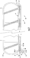
- Figure 1 shows a schematic side view of a people conveyor 1, in particular an escalator 1a, comprising a band 12 of conveyance elements 13 (steps 13a) extending in a longitudinal conveyance direction between two landing portions 20, 21.
- the conveyance elements 13 comprise rollers 23 guided and supported by guide rails (not shown). For clarity, only some of the conveyance elements 13 are depicted in Figure 1 , and not all conveyance elements 13 / rollers 23 are provided with reference signs.
- the band 12 of conveyance elements 13 passes from a conveyance portion 16 into a return portion 18, and vice versa.
- a conveyance chain 15 extending along a closed loop is connected to the band 12 of conveyance elements 13.
- Balustrades 4 supporting moving handrails 6 extend parallel to the conveyance portion 16.
- the conveyance chain 15 is configured for driving the band 12 of conveyance elements 13.
- the conveyance chain 15 is driven by a conveyance chain sprocket 32 mounted to a rotating shaft 30.
- Figure 2 depicts a schematic side view of a people conveyor 1, which is provided as a moving walkway 1b.
- the moving walkway 1b comprises an endless band 12 of conveyance elements 13 (pallets 13b) moving in a longitudinal conveyance direction in an upper conveyance portion 16 and opposite to the conveyance direction in a lower return portion 18.
- Landing portions 20, 21 are provided at both ends of the moving walkway 1b.
- Balustrades 4 supporting moving handrails 6 extend parallel to the conveyance portion 16.
- the band 12 of conveyance elements 13 is connected with an endless conveyance chain 15.
- the endless conveyance chain 15 is in engagement with a conveyance chain sprocket 32.
- the people conveyor 1 further comprises a people conveyor drive 25 including a motor 29, which is configured for driving a drive sprocket 26 (not shown in Figure 2 ).
- a drive chain 27 acting as a transmission element engages with said drive sprocket 26 and a driven sprocket 28 mounted to the rotating shaft 30 for rotating integrally with the conveyance chain sprocket 32.
- the driven sprocket 28 and the conveyance chain sprocket 32 may be formed integrally as a single sprocket comprising two different rims, a first rim corresponding to the conveyance chain sprocket 32 and a second rim corresponding to the driven sprocket 28, respectively.
- the conveyance chain sprocket 32 may be driven by the motor 29 of the people conveyor drive 25 via a mechanical connection provided by the drive sprocket 26, the drive chain 27, and the driven sprocket 28.
- Two or all three sprockets 26, 28, 32 may have the same diameter / number of teeth, or the diameters / numbers of teeth of the sprockets 26, 28, 32 may be different.
- a chain tension monitoring device 40 is arranged next to the drive chain 27.
- Figure 3 depicts an enlarged side view of the drive sprocket 26, the driven sprocket 28, the drive chain 27 extending between and engaging with the two sprockets 26, 28.
- Figure 3 further depicts a chain tension monitoring device 40 according to an exemplary embodiment of the invention.
- the chain tension monitoring device 40 comprises a sensor device 41 with a movable element 42, such as a sliding shoe.
- the movable element 42 is supported by a guide 44 in a configuration allowing the movable element 42 to move, in particular to shift or slide, transversely, in particular orthogonally, to the longitudinal moving direction of the drive chain 27.
- the sensor device 41 further comprises an elastic element 46, such as a spring, configured for urging the movable element 42 against the drive chain 27.
- an elastic element 46 such as a spring, configured for urging the movable element 42 against the drive chain 27.
- the portion of the movable element 42 contacting the drive chain 27 may be covered with a coating 43, such as a coating 43 including Teflon® or a similar material, configured for reducing the wear and the friction between the movable element 42 and the drive chain 27 passing along the outer surface of the movable element 42.
- a coating 43 such as a coating 43 including Teflon® or a similar material, configured for reducing the wear and the friction between the movable element 42 and the drive chain 27 passing along the outer surface of the movable element 42.
- the movable element 42 is mechanically coupled with a motion sensor 48, in particular with an accelerometer.
- the motion sensor 48 is configured for detecting any movement of the movable element 42 transversely, in particular orthogonally, to the longitudinal moving direction of the drive chain 27 and for generating a corresponding detection signal.
- the detection signal generated by the motion sensor (accelerometer) 48 is supplied to an evaluator 50.
- the evaluator 50 is configured for calculating at least one frequency f of the movement of the movable element 42.
- the evaluator 50 in particular may perform a Fourier-Transformation of the detection signal provided by the motion sensor (accelerometer) 48.
- Such a Fourier-Transformation in particular may be implemented as a Fast-Fourier-Transformation (FFT).
- FFT Fast-Fourier-Transformation
- the product ⁇ x r employed in the formula is identical for both sprockets 26, 28.
- the rotational speed ⁇ and the pitch diameter r of any of the two sprockets 26, 28 may be used for the calculation, even if the pitch diameters r of the two sprockets 26, 28 are different, as long as the rotational speed w and the pitch diameter r of the same sprocket 26, 28 are used.
- chordal frequencies f of higher order (k>1) may be used as well.
- the chain tension monitoring device 40 further comprises a controller 52, which is configured for comparing the calculated chain tension force F c with a predefined lower limit F low . In case the calculated chain tension force F c is smaller than said predefined lower limit F low (F c ⁇ F low ), the chain tension force F c is considered as being too low and the controller 52 is configured to issue an alarm signal.
- the controller 52 additionally may be configured for detecting and indicating a too large chain tension force F c , i. e. a chain tension force F c exceeding a predefined upper limit F high (F c > F high ).
- the alarm signal issued by the controller 52 may cause the motor 29 of people conveyor drive 25 to stop in order to avoid a malfunction of the people conveyor 1 and/or damage of the transmission element 27 and/or of the sprockets 26, 28, as it may be caused by a wrong chain tension force F c .
- the people conveyor 1 may comprise a tensioning mechanism 54 configured for adjusting the chain tension force F c , e.g. by moving at least one of the sprockets 26, 28 in the longitudinal direction.
- the alarm signal issued by the controller 52 may trigger the tensioning mechanism 54 to adjust the chain tension force F c .
- the tensioning mechanism 54 in particular may be configured for adjusting the chain tension force F c as long as an alarm signal is issued, i.e. as long as the detected chain tension force F c is smaller than the predefined lower limit F low , or larger than the predefined upper limit F high , respectively.
- Such a configuration allows automatically adjusting the chain tension force F c , thereby preventing undesirable down-times of the people conveyor 1 after a wrong chain tension force F c has been detected.
Landscapes
- Physics & Mathematics (AREA)
- General Physics & Mathematics (AREA)
- Engineering & Computer Science (AREA)
- Mathematical Physics (AREA)
- General Engineering & Computer Science (AREA)
- Data Mining & Analysis (AREA)
- Mathematical Optimization (AREA)
- Pure & Applied Mathematics (AREA)
- Mathematical Analysis (AREA)
- Theoretical Computer Science (AREA)
- Computational Mathematics (AREA)
- Software Systems (AREA)
- Databases & Information Systems (AREA)
- Discrete Mathematics (AREA)
- Algebra (AREA)
- Mechanical Engineering (AREA)
- Chemical & Material Sciences (AREA)
- Analytical Chemistry (AREA)
- Escalators And Moving Walkways (AREA)
- Devices For Conveying Motion By Means Of Endless Flexible Members (AREA)
Abstract
Description
- The invention relates to a device and to a method for monitoring a chain tension force of a drive chain, in particular of a drive chain of a people conveyor. The invention further relates to a people conveyor comprising such a device. In the following, such a device is called "chain tension monitoring device".
- People conveyors such as escalators and moving walkways comprise a band of conveyance elements, such as steps or pallets, moving in a longitudinal conveyance direction. The conveyance elements are connected with and driven by an endless conveyance chain. The conveyance chain may be driven by a people conveyor drive via a drive chain.
- A correct chain tension force of said drive chain is essential for a proper operation of the people conveyor.
- It therefore is desirable to provide a method and a device which allow monitoring the chain tension force of the drive chain, in particular continuously monitoring the chain tension force of the drive chain during operation of the people conveyor.
- According to an exemplary embodiment of the invention, a chain tension monitoring device is configured for monitoring a chain tension force of a drive chain extending in a longitudinal conveyance direction forming a closed loop between two sprockets. The chain tension monitoring device comprises a sensor device and an evaluator. The sensor device is configured for mechanically contacting the drive chain, detecting movement of the drive chain in a direction oriented transversely, in particular orthogonally, to the longitudinal direction of the drive chain, and providing a detection signal indicating the detected movement of the drive chain. The evaluator is configured for receiving the detection signal provided by the sensor device and determining a chain tension force of the drive chain from said detection signal.
- According to an exemplary embodiment of the invention, a method of monitoring a chain tension force of a drive chain extending in a longitudinal direction forming a closed loop between two sprockets, comprises detecting a movement of the chain in a direction oriented transversely, in particular orthogonally, to the longitudinal direction of the drive chain, providing a detection signal indicating the detected movement of the drive chain and determining the chain tension force of the drive chain from said detection signal.
- Exemplary embodiments of the invention also include a people conveyor, in particular an escalator or a moving walkway, comprising a drive chain and a chain tension monitoring device according to an exemplary embodiment of the invention.
- Exemplary embodiments of the invention allow monitoring the chain tension force of a drive chain conveniently and reliably, in particular during operation. In consequence, a suitable chain tension force of the drive chain may be ensured, and operating a people conveyor with a wrong chain tension force of the drive chain, in particular with a too low chain tension force, may be avoided.
- Maintaining a correct chain tension force of the drive chain allows a smooth operation of the people conveyor resulting in good ride quality, low noise and long lifetime of the people conveyor, in particular of its drive chain.
- A number of optional features are set out in the following. These features may be realized in particular embodiments, alone or in combination with any of the other features.
- The sensor device may comprise a movable element, such as a sliding shoe, which is movable transversely, in particular orthogonally, to the longitudinal direction of the drive chain, and which is configured for contacting the drive chain.
- The sensor device may comprise an elastic element configured for urging the movable element against the drive chain and/or an accelerometer configured for detecting movement of the movable element transversely, in particularly orthogonally, to the longitudinal direction, and providing a corresponding signal which may be used as the detection signal.
- Such a mechanical sensor device provides a cheap and reliable sensor device capable of detecting movement of the drive chain in a transverse direction, in particular in a direction oriented orthogonally to the longitudinal direction of the drive chain.
- The evaluator may be configured for determining at least one frequency of the detected movement in order to determine the chain tension force of the drive chain from said at least one frequency.
- The evaluator in particular may be configured for determining the current chain tension force Fc of the drive chain employing the formula:

- L
- is the distance between the two sprockets,
- k
- is the mode number of chordal vibration,
- f
- is the chordal frequency of the respective mode,
- ω
- is the rotational speed of one of the sprockets,
- r
- is the pitch diameter of the respective sprocket,
- m
- is the mass per unit chain length, and
- Cr
- is a resonance factor of the drive chain, which may be determined experimentally.
- Applying said formula allows for a reliable determination of the chain tension force of the drive chain with high accuracy.
- The at least one frequency may be determined by applying a Fast-Fourier-Transformation (FFT) to the detection signal provided by the sensor device, in particular a detection signal representing the varying position of the movable element as a function of time. A Fast-Fourier-Transformation provides a fast and well-established way of determining at least one frequency of a signal.
- The chain tension monitoring device may further comprise a controller configured for comparing the chain tension force determined by the evaluator with a predefined lower limit and issuing an alarm signal in case the chain tension force determined by the evaluator is smaller than the predefined lower limit.
- The chain tension monitoring device may also comprise a controller configured for comparing the chain tension force determined by the evaluator with a predefined upper limit and issuing an alarm signal in case the chain tension force determined by the evaluator exceeds the predefined upper limit.
- Such a controller allows notifying service personnel and/or stopping operation of the people conveyor in case the chain tension force of the drive chain drops below the predefined lower limit or exceeds the predefined upper limit. This avoids operating the people conveyor over an extended period of time with a chain tension force of the drive chain which is too small or too large. Operating the people conveyor with a wrong chain tension force over an extended period of time increases the wear of at least some components of the people conveyor and reduces the riding comfort for the passengers. It even might cause damage of components of the people conveyor.
- A chain tension monitoring device according to an embodiment of the invention may further comprise a tensioning mechanism coupled with the controller and configured for adjusting, i.e. increasing or decreasing, the chain tension force of the drive chain when an alarm signal is issued because the determined chain tension force falls below the lower limit or exceeds the upper limit.
- Such a configuration allows automatically compensating for a wrong chain tension force without stopping the operation of the people conveyor. It further avoids the need for a mechanic to visit the people conveyor in order to adjust the chain tension force.
- A people conveyor according to an exemplary embodiment of the invention may be an escalator, in which the conveyance elements are steps.
- Alternatively, the people conveyor may be a moving walkway, in which the conveyance elements are pallets. In case of a moving walkway, the band of conveyance elements (pallets) may be inclined with respect to the horizontal, or it may extend horizontally.
- In the following exemplary embodiments of the invention are described with reference to the enclosed figures.
-
Figure 1 depicts a schematic side view of an escalator. -
Figure 2 depicts a schematic side view of a moving walkway. -
Figure 3 depicts an enlarged side view of a transmission element and a chain tension monitoring device according to an exemplary embodiment of the invention. -
Figure 1 shows a schematic side view of apeople conveyor 1, in particular an escalator 1a, comprising aband 12 of conveyance elements 13 (steps 13a) extending in a longitudinal conveyance direction between twolanding portions rollers 23 guided and supported by guide rails (not shown). For clarity, only some of the conveyance elements 13 are depicted inFigure 1 , and not all conveyance elements 13 /rollers 23 are provided with reference signs. - In
turnaround portions 17 next to thelanding portions band 12 of conveyance elements 13 passes from aconveyance portion 16 into areturn portion 18, and vice versa. Aconveyance chain 15 extending along a closed loop is connected to theband 12 of conveyance elements 13. Balustrades 4 supporting movinghandrails 6 extend parallel to theconveyance portion 16. - The
conveyance chain 15 is configured for driving theband 12 of conveyance elements 13. Theconveyance chain 15 is driven by aconveyance chain sprocket 32 mounted to a rotatingshaft 30. -
Figure 2 depicts a schematic side view of apeople conveyor 1, which is provided as a moving walkway 1b. - The moving walkway 1b comprises an
endless band 12 of conveyance elements 13 (pallets 13b) moving in a longitudinal conveyance direction in anupper conveyance portion 16 and opposite to the conveyance direction in alower return portion 18. Landingportions turnaround portions 17 next to thelanding portions band 12 of conveyance elements 13 passes from theconveyance portion 16 into thereturn portion 18, and vice versa.Balustrades 4 supporting movinghandrails 6 extend parallel to theconveyance portion 16. - Similar to the embodiment shown in
Figure 1 , theband 12 of conveyance elements 13 is connected with anendless conveyance chain 15. In at least one of theturnaround portions 17, theendless conveyance chain 15 is in engagement with aconveyance chain sprocket 32. - In both configurations depicted in
Figures 1 and2 , thepeople conveyor 1 further comprises a people conveyor drive 25 including amotor 29, which is configured for driving a drive sprocket 26 (not shown inFigure 2 ). - A
drive chain 27 acting as a transmission element engages with saiddrive sprocket 26 and a drivensprocket 28 mounted to therotating shaft 30 for rotating integrally with theconveyance chain sprocket 32. Optionally, the drivensprocket 28 and theconveyance chain sprocket 32 may be formed integrally as a single sprocket comprising two different rims, a first rim corresponding to theconveyance chain sprocket 32 and a second rim corresponding to the drivensprocket 28, respectively. - As a result, the
conveyance chain sprocket 32 may be driven by themotor 29 of the people conveyor drive 25 via a mechanical connection provided by thedrive sprocket 26, thedrive chain 27, and the drivensprocket 28. - Two or all three
sprockets sprockets - In both configurations depicted in
Figures 1 and2 , a chaintension monitoring device 40 according to an exemplary embodiment of the invention is arranged next to thedrive chain 27. -
Figure 3 depicts an enlarged side view of thedrive sprocket 26, the drivensprocket 28, thedrive chain 27 extending between and engaging with the twosprockets Figure 3 further depicts a chaintension monitoring device 40 according to an exemplary embodiment of the invention. - The chain
tension monitoring device 40 comprises asensor device 41 with amovable element 42, such as a sliding shoe. Themovable element 42 is supported by aguide 44 in a configuration allowing themovable element 42 to move, in particular to shift or slide, transversely, in particular orthogonally, to the longitudinal moving direction of thedrive chain 27. - The
sensor device 41 further comprises anelastic element 46, such as a spring, configured for urging themovable element 42 against thedrive chain 27. As a result, the position of themovable element 42 with respect to theguide 44 is determined by the interaction between the urging force applied by theelastic element 46 and the chain tension force Fc of thedrive chain 27. - The portion of the
movable element 42 contacting thedrive chain 27 may be covered with acoating 43, such as acoating 43 including Teflon® or a similar material, configured for reducing the wear and the friction between themovable element 42 and thedrive chain 27 passing along the outer surface of themovable element 42. - The
movable element 42 is mechanically coupled with amotion sensor 48, in particular with an accelerometer. Themotion sensor 48 is configured for detecting any movement of themovable element 42 transversely, in particular orthogonally, to the longitudinal moving direction of thedrive chain 27 and for generating a corresponding detection signal. - The detection signal generated by the motion sensor (accelerometer) 48 is supplied to an
evaluator 50. - The
evaluator 50 is configured for calculating at least one frequency f of the movement of themovable element 42. Theevaluator 50 in particular may perform a Fourier-Transformation of the detection signal provided by the motion sensor (accelerometer) 48. Such a Fourier-Transformation in particular may be implemented as a Fast-Fourier-Transformation (FFT). - The chain tension force Fc of the
drive chain 27 may be calculated from said at least one frequency f using the formula:
- In said formula,
- L
- is the distance between the two
sprockets - k
- is the mode number of chordal vibration,
- f
- is the chordal frequency of the respective mode,
- m
- is the mass per unit chain length,
- ω
- is the rotational speed of one of the
sprockets - r
- is the pitch diameter of the
respective sprocket - Cr
- is a resonance factor of the
drive chain 27, which may be determined experimentally. - It is noted that the product ω x r employed in the formula is identical for both
sprockets sprockets sprockets same sprocket - Usually, the first chordal frequency f (k=1) is used, which in the case of a people conveyor usually is less than 1 Hz. However chordal frequencies f of higher order (k>1) may be used as well.
- The chain
tension monitoring device 40 further comprises acontroller 52, which is configured for comparing the calculated chain tension force Fc with a predefined lower limit Flow. In case the calculated chain tension force Fc is smaller than said predefined lower limit Flow (Fc < Flow), the chain tension force Fc is considered as being too low and thecontroller 52 is configured to issue an alarm signal. - Alternatively or additionally, the
controller 52 additionally may be configured for detecting and indicating a too large chain tension force Fc, i. e. a chain tension force Fc exceeding a predefined upper limit Fhigh (Fc > Fhigh). - The alarm signal issued by the
controller 52 may cause themotor 29 of people conveyor drive 25 to stop in order to avoid a malfunction of thepeople conveyor 1 and/or damage of thetransmission element 27 and/or of thesprockets - Optionally, the
people conveyor 1 may comprise atensioning mechanism 54 configured for adjusting the chain tension force Fc, e.g. by moving at least one of thesprockets controller 52 may trigger thetensioning mechanism 54 to adjust the chain tension force Fc. - The
tensioning mechanism 54 in particular may be configured for adjusting the chain tension force Fc as long as an alarm signal is issued, i.e. as long as the detected chain tension force Fc is smaller than the predefined lower limit Flow, or larger than the predefined upper limit Fhigh, respectively. - Such a configuration allows automatically adjusting the chain tension force Fc, thereby preventing undesirable down-times of the
people conveyor 1 after a wrong chain tension force Fc has been detected. - In case the
tensioning mechanism 54 does not succeed in increasing the chain tension force Fc at least to the predefined lower limit Flow, or decreasing the chain tension force Fc at least to the predefined upper limit Fhigh, within a predetermined amount of time, further operation of the people conveyor drive 25 may be stopped and a mechanic may be requested to visit thepeople conveyor 1 in order to fix the problem. - While the invention has been described with reference to exemplary embodiments, it will be understood by those skilled in the art that various changes may be made and equivalents may be substituted for elements thereof without departing from the scope of the invention. In addition, many modifications may be made to adopt a particular situation or material to the teachings of the invention without departing from the essential scope thereof. Therefore, it is intended that the invention shall not be limited to the particular embodiment disclosed, but that the invention includes all embodiments falling within the scope of the dependent claims.
-
- 1
- people conveyor
- 1a
- escalator
- 1b
- moving walkway
- 4
- balustrade
- 6
- moving handrail
- 12
- band of conveyance elements
- 13
- conveyance elements
- 13a
- steps
- 13b
- pallets
- 15
- conveyance chain / first drive chain
- 16
- conveyance portion
- 17
- turnaround portion
- 18
- return portion
- 20, 21
- landing portions
- 23
- rollers
- 25
- people conveyor drive
- 26
- drive sprocket
- 27
- transmission element / second drive chain
- 28
- driven sprocket
- 29
- motor
- 30
- rotating shaft
- 32
- conveyance chain sprocket
- 40
- chain tension monitoring device
- 41
- sensor device
- 42
- movable element / sliding shoe
- 43
- coating
- 44
- guide
- 46
- elastic element / spring
- 48
- motion sensor / accelerometer
- 50
- evaluator
- 52
- controller
- 54
- tensioning mechanism
- Cr
- resonance factor of the drive chain
- FC
- chain tension force
- Fhigh
- upper limit of the chain tension force
- Flow
- lower limit of the chain tension force
- f
- chordal frequency
- k
- mode number of chordal vibration
- L
- distance between the sprockets
- m
- mass per unit chain length,
- r
- pitch diameter
- ω
- rotational speed
Claims (15)
- Chain tension monitoring device (40) configured for monitoring a chain tension force (Fc) of a drive chain (27) extending in a longitudinal direction forming a closed loop between two sprockets (26, 28), the chain tension monitoring device (40) comprising:a sensor device (41) configured for mechanically contacting the drive chain (27), detecting a movement of the drive chain (27) transversely, in particular orthogonally, to the longitudinal direction of the drive chain (27), and providing a detection signal indicating the detected movement of the drive chain (27); andan evaluator (50) configured for receiving the detection signal provided by the sensor device (41) and determining a chain tension force (Fc) of the drive chain (27) from said detection signal.
- Chain tension monitoring device (40) according to claim 1, wherein the evaluator (50) is configured for determining at least one frequency (f) of the detected movement, in particular by employing a Fast-Fourier-Transformation.
- Chain tension monitoring device (40) according to claim 2, wherein the evaluator (50) is configured for determining the current chain tension force (Fc) of the drive chain (27) employing the formula:
 Cr is a resonance factor of the drive chain (27),L is the distance between the two sprockets (26, 28),k is the mode number of chordal vibration,f is the chordal frequency of the respective mode,ω is the rotational speed of one of the sprockets (26, 28),r is the pitch diameter of the respective sprocket (26, 28), andm is the mass per unit chain length.
 - Chain tension monitoring device (40) according to any of the preceding claims, wherein the sensor device (41) comprises
a movable element (42), in particular a sliding shoe, which is configured for contacting the drive chain (27), and which is movable perpendicularly to the longitudinal direction of the drive chain (27). - Chain tension monitoring device (40) according to claim 4, comprising
an elastic element (46), in particular a spring, configured for urging the movable element (42) against the drive chain (27). - Chain tension monitoring device (40) according to claim 4 or 5, comprising a motion sensor (48) configured for detecting a movement of the movable element (42) transversely, in particular orthogonally, to the longitudinal direction of the drive chain (27), and providing a corresponding detection signal.
- Chain tension monitoring device (40) according to any of the preceding claims, further comprising a controller (52) configured for comparing the chain tension force (Fc) determined by the evaluator (50) with a predefined lower limit (Flow) and/or with a predefined upper limit (Fhigh) and issuing an alarm signal in case the chain tension force (Fc) determined by the evaluator (50) is smaller than the predefined lower limit (Flow) or in case the chain tension force (Fc) determined by the evaluator (50) is larger than the predefined lower limit (Fhigh).
- Chain tension monitoring device (40) according to claim 7 further comprising a tensioning mechanism (54) coupled with the controller (52) and configured for adjusting the chain tension force (Fc) of the drive chain (27) when an alarm signal is issued.
- People conveyor (1), in particular an escalator (1a) or a moving walkway (1b), comprising a drive chain (27) and a chain tension monitoring device (40) according to any of the preceding claims.
- Method of monitoring the chain tension force of a drive chain (27) extending in a longitudinal direction forming a closed loop between two sprockets (26, 28), the method comprising:detecting a movement of the drive chain (27) transversely, in particular orthogonally, to the longitudinal direction of the drive chain (27);providing a detection signal indicating the detected movement of the drive chain (27); anddetermining a chain tension force (Fc) of the drive chain (27) from said detection signal.
- Method according to claim 10, wherein the method includes determining at least one frequency (f) of the detected movement, in particular by employing a Fast-Fourier-Transformation.
- Method according to claim 11, wherein the method includes determining the current chain tension force (Fc) of the drive chain (27) employing the formula:
 Cr is a resonance factor of the drive chain (27),L is the distance between the two sprockets (26, 28),k is the mode number of chordal vibration,f is the chordal frequency of the respective mode,ω is the rotational speed of one of the sprockets (26, 28),r is the pitch diameter of the respective sprocket, andm is the mass per unit chain length.
 - Method according to any of claims 10 to 12, wherein the method includes elastically urging a movable element (42), in particular a sliding shoe, against the drive chain (27) and detecting a movement of the movable element (42) transversely, in particular orthogonally, to the longitudinal direction of the drive chain (27).
- Method according to any of claims 10 to 13, wherein the method includes comparing the determined chain tension force (Fc) with a predefined lower limit (Flow), and issuing an alarm signal and/or increasing the chain tension force (Fc) of the drive chain (27) in case the determined chain tension force (Fc) is smaller than said predefined lower limit (Flow),
- Method according to any of claims 10 to 14, wherein the method includes comparing the determined chain tension force (Fc) with a predefined upper limit (Fhigh), and issuing an alarm signal and/or decreasing the chain tension force (Fc) of the drive chain (27) in case the determined chain tension force (Fc) is larger than said predefined upper limit (Fhigh).
Priority Applications (3)
| Application Number | Priority Date | Filing Date | Title |
|---|---|---|---|
| EP18213959.2A EP3670419B1 (en) | 2018-12-19 | 2018-12-19 | Method and device for monitoring chain tension |
| US16/717,829 US11150151B2 (en) | 2018-12-19 | 2019-12-17 | Method and device for monitoring chain tension |
| CN201911317393.8A CN111332926B (en) | 2018-12-19 | 2019-12-19 | Method and device for monitoring chain tension |
Applications Claiming Priority (1)
| Application Number | Priority Date | Filing Date | Title |
|---|---|---|---|
| EP18213959.2A EP3670419B1 (en) | 2018-12-19 | 2018-12-19 | Method and device for monitoring chain tension |
Publications (2)
| Publication Number | Publication Date |
|---|---|
| EP3670419A1 true EP3670419A1 (en) | 2020-06-24 |
| EP3670419B1 EP3670419B1 (en) | 2023-01-25 |
Family
ID=64746118
Family Applications (1)
| Application Number | Title | Priority Date | Filing Date |
|---|---|---|---|
| EP18213959.2A Active EP3670419B1 (en) | 2018-12-19 | 2018-12-19 | Method and device for monitoring chain tension |
Country Status (3)
| Country | Link |
|---|---|
| US (1) | US11150151B2 (en) |
| EP (1) | EP3670419B1 (en) |
| CN (1) | CN111332926B (en) |
Cited By (1)
| Publication number | Priority date | Publication date | Assignee | Title |
|---|---|---|---|---|
| CN112093621A (en) * | 2020-08-27 | 2020-12-18 | 张学伦 | Tension measuring instrument and application thereof in measuring balance coefficient and compensation effect of elevator |
Families Citing this family (7)
| Publication number | Priority date | Publication date | Assignee | Title |
|---|---|---|---|---|
| JP6968957B1 (en) * | 2020-09-02 | 2021-11-24 | 東芝エレベータ株式会社 | Diagnostic system |
| JP7692729B2 (en) * | 2021-05-13 | 2025-06-16 | 三菱電機ビルソリューションズ株式会社 | How to measure tension of handrail chains on passenger conveyors |
| US12405179B2 (en) * | 2022-04-13 | 2025-09-02 | Sst Systems, Inc | Torque monitoring system for flexible drives |
| CN117282674A (en) * | 2022-06-17 | 2023-12-26 | 苏州金峰物流设备有限公司 | Chain automatic online adjustment method, system and chain-driven trolley sorting machine |
| USD983275S1 (en) * | 2023-01-16 | 2023-04-11 | Ruixiong Huang | Spinning toy |
| CN118894436A (en) * | 2023-05-05 | 2024-11-05 | 奥的斯电梯公司 | Automatic conveying device and maintenance method thereof |
| CN116698258A (en) * | 2023-06-08 | 2023-09-05 | 中国第一汽车股份有限公司 | Method and system for determining chain tension of V-shaped engine |
Citations (4)
| Publication number | Priority date | Publication date | Assignee | Title |
|---|---|---|---|---|
| JP2000143136A (en) * | 1998-11-12 | 2000-05-23 | Hitachi Building Systems Co Ltd | Passenger conveyor chain tension measuring device |
| US20050187053A1 (en) * | 2003-12-19 | 2005-08-25 | Otis Elevator Company | Device for monitoring abnormality in a chain |
| US20110220699A1 (en) * | 2008-09-11 | 2011-09-15 | Multivac Sepp Haggenmuller Gmbh & Co. Kg | Packaging machine with dynamic chain tension |
| JP2016183034A (en) * | 2015-03-26 | 2016-10-20 | 三菱電機ビルテクノサービス株式会社 | Escalator drive unit to manage drive chain tension |
Family Cites Families (54)
| Publication number | Priority date | Publication date | Assignee | Title |
|---|---|---|---|---|
| US2985027A (en) * | 1958-11-28 | 1961-05-23 | James J Murray | Slack adjuster |
| US3054299A (en) * | 1960-08-17 | 1962-09-18 | Sperry Rand Corp | Tightener |
| US3413866A (en) * | 1966-10-14 | 1968-12-03 | Byron C. Ford | Belt tensioning device |
| US3675482A (en) * | 1970-10-14 | 1972-07-11 | Goodyear Tire & Rubber | Automatic tension sensing apparatus for belt conveyor |
| US3945264A (en) * | 1974-06-03 | 1976-03-23 | Douglass Manufacturing Company, Inc. | Reaction support for pulley holddown |
| US4082173A (en) * | 1976-06-10 | 1978-04-04 | Otis Elevator Company | Drive unit for an endless conveyor |
| IT1088413B (en) * | 1977-12-06 | 1985-06-10 | M P R E Spa Sa | TENSIONER DEVICE OF A BELT TO CONTROL THE ROTATION OF ALIGNED ORGANS, SUCH AS TEXTILE MACHINE SPINDLES |
| US4466802A (en) * | 1981-03-03 | 1984-08-21 | Nhk Spring Co., Ltd. | Tension providing mechanism |
| US4499971A (en) * | 1983-04-22 | 1985-02-19 | Crown Controls Corporation | Material handling vehicle having improved chain monitoring |
| DE3406519A1 (en) | 1984-02-23 | 1985-08-29 | Bergwerksverband Gmbh, 4300 Essen | TENSIONING DEVICE FOR CHAIN DRIVED AGENTS |
| US4826470A (en) * | 1988-07-01 | 1989-05-02 | Eaton Corporation | Fluid operated chain or belt tensioning device |
| GB2232741B (en) * | 1989-06-10 | 1992-12-23 | Unisys Corp | Belt tensioning apparatus |
| US5143206A (en) * | 1991-06-11 | 1992-09-01 | Ctb, Inc. | Rod conveyor switch |
| JPH08198573A (en) | 1995-01-25 | 1996-08-06 | Hitachi Building Syst Eng & Service Co Ltd | Escalator handrail drive chain tension detector |
| US5720683A (en) * | 1996-10-21 | 1998-02-24 | Borg-Warner Automotive,Inc. | Mechanical chain tensioner with belleville springs |
| US5951423A (en) * | 1997-10-08 | 1999-09-14 | Borg-Warner Automotive, Inc. | Mechanical friction tensioner |
| US6137974A (en) * | 1998-12-21 | 2000-10-24 | Xerox Corporation | Photoreceptor belt tensioner system |
| US6435035B1 (en) * | 1999-11-23 | 2002-08-20 | Jervis B. Webb Company | Chain tension monitoring apparatus and method |
| US6358169B1 (en) * | 2000-05-02 | 2002-03-19 | Borgwarner Inc. | Chain tensioner system having a pivoting tensioner arm |
| US6852050B2 (en) * | 2002-04-17 | 2005-02-08 | Carrier Commercial Refrigeration, Inc. | Lateral sensor for conveyor belt |
| DE20210210U1 (en) | 2002-07-02 | 2003-01-09 | Thyssen Fahrtreppen GmbH, 22113 Hamburg | Escalator or moving pavement has inductive or capacitive travel sensor transmitting output signal continuously in dependence upon distance covered from bearing of chain wheel |
| US6726532B2 (en) * | 2002-07-24 | 2004-04-27 | Taiwan Semiconductor Manufacturing Co., Ltd | Belt tensioning assembly for CMP apparatus |
| JP2005029362A (en) | 2003-07-08 | 2005-02-03 | Mitsubishi Electric Building Techno Service Co Ltd | Chain tension measuring device for passenger conveyor |
| US7185546B2 (en) * | 2004-06-14 | 2007-03-06 | Ascenx | Systems and methods for measuring belt tension |
| JP2006273549A (en) | 2005-03-30 | 2006-10-12 | Mitsubishi Electric Building Techno Service Co Ltd | Elongation sensing device for step chain of man conveyor |
| EP1850087B1 (en) | 2006-04-25 | 2009-08-19 | Prüftechnik Dieter Busch Ag | Method and apparatus for monitoring the elongation of a drive chain |
| JP2007309488A (en) * | 2006-05-22 | 2007-11-29 | Tsubakimoto Chain Co | Roller chain transmission device |
| US7837021B2 (en) | 2006-09-01 | 2010-11-23 | Mitsubishi Electric Corporation | Passenger conveyor |
| KR100810610B1 (en) * | 2006-10-25 | 2008-03-07 | 삼성전자주식회사 | Belt tensioning device and robot arm having same |
| JP5314888B2 (en) * | 2007-12-27 | 2013-10-16 | 株式会社日立製作所 | Automatic diagnostic operation device for passenger conveyor |
| GB2469816B (en) | 2009-04-28 | 2012-10-31 | Joy Mm Delaware Inc | Conveyor sensor arrangement |
| GB2471826B (en) | 2009-04-28 | 2014-02-12 | Joy Mm Delaware Inc | Dual sensor chain break detector |
| KR101096780B1 (en) | 2010-07-29 | 2011-12-21 | 한국과학기술원 | Energy Harvesting Lifting Device |
| WO2013033822A1 (en) * | 2011-09-05 | 2013-03-14 | Litens Automotive Partnership | Intelligent belt drive system and method |
| CN104903692B (en) * | 2012-12-12 | 2018-01-12 | 阪东化学株式会社 | Intrinsic frequency measurement apparatus, belt tension computational methods and with calculation method for natural frequencies and computer readable recording medium storing program for performing |
| JP2015174765A (en) * | 2014-03-18 | 2015-10-05 | 船井電機株式会社 | image forming apparatus |
| CN106715310B (en) | 2014-09-11 | 2019-06-28 | 奥的斯电梯公司 | Vibration-based elevator traction member wear and life monitoring system |
| US10118802B2 (en) | 2014-10-31 | 2018-11-06 | Otis Elevator Company | Structural health monitoring of an escalator drive system |
| JP2016098045A (en) * | 2014-11-18 | 2016-05-30 | 東芝エレベータ株式会社 | Chain looseness detection device of passenger conveyor |
| DE102014226906B4 (en) * | 2014-12-23 | 2020-04-02 | Voith Patent Gmbh | Method for operating a chain drive and arrangement with a chain drive |
| JP6058755B1 (en) | 2015-07-09 | 2017-01-11 | 東芝エレベータ株式会社 | Chain extension detecting device for passenger conveyor and passenger conveyor |
| CN105784241B (en) | 2016-03-07 | 2018-04-13 | 中国矿业大学 | A kind of scraper conveyer chain tension force evaluation method |
| EP3287410B1 (en) * | 2016-08-24 | 2020-02-26 | Otis Elevator Company | Passenger conveyor and method for monitoring vibrations in a passenger conveyor |
| DE112016007470T5 (en) * | 2016-11-24 | 2019-08-14 | Mitsubishi Electric Corporation | CHAIN STRETCH DETECTION DEVICE, CHAIN STRETCH DETECTION METHOD AND PASSENGER TRANSPORT BELT |
| US10180179B2 (en) * | 2017-01-23 | 2019-01-15 | Schiller Grounds Care, Inc. | Chain tension control mechanism |
| DE102017110192B3 (en) * | 2017-05-11 | 2018-10-31 | Schaeffler Technologies AG & Co. KG | Method for detecting belt slippage |
| EP3406559A1 (en) * | 2017-05-24 | 2018-11-28 | Otis Elevator Company | People conveyor |
| CN107416659B (en) * | 2017-09-01 | 2020-10-02 | 通力股份公司 | Drive chain tensioning device and method and escalator system using same |
| EP3473577B1 (en) * | 2017-10-18 | 2022-08-17 | Otis Elevator Company | People conveyor and method of determining power for driving a handrail element of a people conveyor |
| CH714596A1 (en) * | 2018-01-26 | 2019-07-31 | Ferag Ag | Measuring device for acquiring measured values for measuring a tensile stress in a conveyor system, as well as conveyor unit and conveyor system. |
| EP3569558B1 (en) * | 2018-05-16 | 2022-07-13 | Otis Elevator Company | Chain defect monitoring in a people conveyor |
| US11105401B2 (en) * | 2018-07-25 | 2021-08-31 | Gates Corporation | Belt sensor system |
| EP3599212B1 (en) * | 2018-07-27 | 2024-06-12 | Otis Elevator Company | Drive misalignment monitoring in a people conveyor |
| CN110921478B (en) * | 2018-09-19 | 2023-08-04 | 奥的斯电梯公司 | Automatic handrail belt tensioning system and method for adjusting tensioning degree of handrail belt |
-
2018
- 2018-12-19 EP EP18213959.2A patent/EP3670419B1/en active Active
-
2019
- 2019-12-17 US US16/717,829 patent/US11150151B2/en active Active
- 2019-12-19 CN CN201911317393.8A patent/CN111332926B/en active Active
Patent Citations (4)
| Publication number | Priority date | Publication date | Assignee | Title |
|---|---|---|---|---|
| JP2000143136A (en) * | 1998-11-12 | 2000-05-23 | Hitachi Building Systems Co Ltd | Passenger conveyor chain tension measuring device |
| US20050187053A1 (en) * | 2003-12-19 | 2005-08-25 | Otis Elevator Company | Device for monitoring abnormality in a chain |
| US20110220699A1 (en) * | 2008-09-11 | 2011-09-15 | Multivac Sepp Haggenmuller Gmbh & Co. Kg | Packaging machine with dynamic chain tension |
| JP2016183034A (en) * | 2015-03-26 | 2016-10-20 | 三菱電機ビルテクノサービス株式会社 | Escalator drive unit to manage drive chain tension |
Cited By (2)
| Publication number | Priority date | Publication date | Assignee | Title |
|---|---|---|---|---|
| CN112093621A (en) * | 2020-08-27 | 2020-12-18 | 张学伦 | Tension measuring instrument and application thereof in measuring balance coefficient and compensation effect of elevator |
| CN112093621B (en) * | 2020-08-27 | 2023-03-10 | 张学伦 | Tension measuring instrument and application thereof in measuring balance coefficient and compensation effect of elevator |
Also Published As
| Publication number | Publication date |
|---|---|
| CN111332926B (en) | 2021-09-28 |
| CN111332926A (en) | 2020-06-26 |
| US20200200628A1 (en) | 2020-06-25 |
| EP3670419B1 (en) | 2023-01-25 |
| US11150151B2 (en) | 2021-10-19 |
Similar Documents
| Publication | Publication Date | Title |
|---|---|---|
| US11150151B2 (en) | Method and device for monitoring chain tension | |
| EP3287410B1 (en) | Passenger conveyor and method for monitoring vibrations in a passenger conveyor | |
| JP2019152514A (en) | Diagnosing device | |
| JP5050362B2 (en) | elevator | |
| EP0599452A1 (en) | Passenger conveyor missing step detection | |
| JP7797494B2 (en) | Handrail tension monitoring device for passenger transit systems | |
| US10954104B2 (en) | Chain defect monitoring in a people conveyor | |
| JP6479941B1 (en) | Anomaly detection system for passenger conveyors | |
| US10850947B2 (en) | Misalignment monitoring in a people conveyor | |
| EP0580425A1 (en) | Tension adjusting device for escalator or moving walkway handrails | |
| US10689231B2 (en) | Belt safety device and people conveyor with a belt safety device | |
| US10954103B2 (en) | People conveyor and method of determining power for driving a handrail element of a people conveyor | |
| JP2003321186A (en) | Passenger conveyor operation management device | |
| US10974931B2 (en) | Run-in guide rail for escalators or moving walkways and passenger conveyance device having a run-in guide rail of this kind | |
| JPS6218615Y2 (en) | ||
| HK40069729A (en) | Diagnostic system | |
| HK1247177A1 (en) | A detection device for conveyor, a conveyor, and an associated method | |
| HK1247177A (en) | A detection device for conveyor, a conveyor, and an associated method |
Legal Events
| Date | Code | Title | Description |
|---|---|---|---|
| PUAI | Public reference made under article 153(3) epc to a published international application that has entered the european phase |
Free format text: ORIGINAL CODE: 0009012 |
|
| STAA | Information on the status of an ep patent application or granted ep patent |
Free format text: STATUS: THE APPLICATION HAS BEEN PUBLISHED |
|
| AK | Designated contracting states |
Kind code of ref document: A1 Designated state(s): AL AT BE BG CH CY CZ DE DK EE ES FI FR GB GR HR HU IE IS IT LI LT LU LV MC MK MT NL NO PL PT RO RS SE SI SK SM TR |
|
| AX | Request for extension of the european patent |
Extension state: BA ME |
|
| STAA | Information on the status of an ep patent application or granted ep patent |
Free format text: STATUS: REQUEST FOR EXAMINATION WAS MADE |
|
| 17P | Request for examination filed |
Effective date: 20201117 |
|
| RBV | Designated contracting states (corrected) |
Designated state(s): AL AT BE BG CH CY CZ DE DK EE ES FI FR GB GR HR HU IE IS IT LI LT LU LV MC MK MT NL NO PL PT RO RS SE SI SK SM TR |
|
| STAA | Information on the status of an ep patent application or granted ep patent |
Free format text: STATUS: EXAMINATION IS IN PROGRESS |
|
| 17Q | First examination report despatched |
Effective date: 20211011 |
|
| 17Q | First examination report despatched |
Effective date: 20211022 |
|
| GRAP | Despatch of communication of intention to grant a patent |
Free format text: ORIGINAL CODE: EPIDOSNIGR1 |
|
| STAA | Information on the status of an ep patent application or granted ep patent |
Free format text: STATUS: GRANT OF PATENT IS INTENDED |
|
| INTG | Intention to grant announced |
Effective date: 20220902 |
|
| GRAS | Grant fee paid |
Free format text: ORIGINAL CODE: EPIDOSNIGR3 |
|
| GRAA | (expected) grant |
Free format text: ORIGINAL CODE: 0009210 |
|
| STAA | Information on the status of an ep patent application or granted ep patent |
Free format text: STATUS: THE PATENT HAS BEEN GRANTED |
|
| AK | Designated contracting states |
Kind code of ref document: B1 Designated state(s): AL AT BE BG CH CY CZ DE DK EE ES FI FR GB GR HR HU IE IS IT LI LT LU LV MC MK MT NL NO PL PT RO RS SE SI SK SM TR |
|
| REG | Reference to a national code |
Ref country code: GB Ref legal event code: FG4D |
|
| REG | Reference to a national code |
Ref country code: CH Ref legal event code: EP |
|
| REG | Reference to a national code |
Ref country code: DE Ref legal event code: R096 Ref document number: 602018045694 Country of ref document: DE |
|
| REG | Reference to a national code |
Ref country code: AT Ref legal event code: REF Ref document number: 1545799 Country of ref document: AT Kind code of ref document: T Effective date: 20230215 Ref country code: IE Ref legal event code: FG4D |
|
| REG | Reference to a national code |
Ref country code: LT Ref legal event code: MG9D |
|
| REG | Reference to a national code |
Ref country code: NL Ref legal event code: MP Effective date: 20230125 |
|
| REG | Reference to a national code |
Ref country code: AT Ref legal event code: MK05 Ref document number: 1545799 Country of ref document: AT Kind code of ref document: T Effective date: 20230125 |
|
| PG25 | Lapsed in a contracting state [announced via postgrant information from national office to epo] |
Ref country code: NL Free format text: LAPSE BECAUSE OF FAILURE TO SUBMIT A TRANSLATION OF THE DESCRIPTION OR TO PAY THE FEE WITHIN THE PRESCRIBED TIME-LIMIT Effective date: 20230125 |
|
| PG25 | Lapsed in a contracting state [announced via postgrant information from national office to epo] |
Ref country code: RS Free format text: LAPSE BECAUSE OF FAILURE TO SUBMIT A TRANSLATION OF THE DESCRIPTION OR TO PAY THE FEE WITHIN THE PRESCRIBED TIME-LIMIT Effective date: 20230125 Ref country code: PT Free format text: LAPSE BECAUSE OF FAILURE TO SUBMIT A TRANSLATION OF THE DESCRIPTION OR TO PAY THE FEE WITHIN THE PRESCRIBED TIME-LIMIT Effective date: 20230525 Ref country code: NO Free format text: LAPSE BECAUSE OF FAILURE TO SUBMIT A TRANSLATION OF THE DESCRIPTION OR TO PAY THE FEE WITHIN THE PRESCRIBED TIME-LIMIT Effective date: 20230425 Ref country code: LV Free format text: LAPSE BECAUSE OF FAILURE TO SUBMIT A TRANSLATION OF THE DESCRIPTION OR TO PAY THE FEE WITHIN THE PRESCRIBED TIME-LIMIT Effective date: 20230125 Ref country code: LT Free format text: LAPSE BECAUSE OF FAILURE TO SUBMIT A TRANSLATION OF THE DESCRIPTION OR TO PAY THE FEE WITHIN THE PRESCRIBED TIME-LIMIT Effective date: 20230125 Ref country code: HR Free format text: LAPSE BECAUSE OF FAILURE TO SUBMIT A TRANSLATION OF THE DESCRIPTION OR TO PAY THE FEE WITHIN THE PRESCRIBED TIME-LIMIT Effective date: 20230125 Ref country code: ES Free format text: LAPSE BECAUSE OF FAILURE TO SUBMIT A TRANSLATION OF THE DESCRIPTION OR TO PAY THE FEE WITHIN THE PRESCRIBED TIME-LIMIT Effective date: 20230125 Ref country code: AT Free format text: LAPSE BECAUSE OF FAILURE TO SUBMIT A TRANSLATION OF THE DESCRIPTION OR TO PAY THE FEE WITHIN THE PRESCRIBED TIME-LIMIT Effective date: 20230125 |
|
| PG25 | Lapsed in a contracting state [announced via postgrant information from national office to epo] |
Ref country code: SE Free format text: LAPSE BECAUSE OF FAILURE TO SUBMIT A TRANSLATION OF THE DESCRIPTION OR TO PAY THE FEE WITHIN THE PRESCRIBED TIME-LIMIT Effective date: 20230125 Ref country code: PL Free format text: LAPSE BECAUSE OF FAILURE TO SUBMIT A TRANSLATION OF THE DESCRIPTION OR TO PAY THE FEE WITHIN THE PRESCRIBED TIME-LIMIT Effective date: 20230125 Ref country code: IS Free format text: LAPSE BECAUSE OF FAILURE TO SUBMIT A TRANSLATION OF THE DESCRIPTION OR TO PAY THE FEE WITHIN THE PRESCRIBED TIME-LIMIT Effective date: 20230525 Ref country code: GR Free format text: LAPSE BECAUSE OF FAILURE TO SUBMIT A TRANSLATION OF THE DESCRIPTION OR TO PAY THE FEE WITHIN THE PRESCRIBED TIME-LIMIT Effective date: 20230426 Ref country code: FI Free format text: LAPSE BECAUSE OF FAILURE TO SUBMIT A TRANSLATION OF THE DESCRIPTION OR TO PAY THE FEE WITHIN THE PRESCRIBED TIME-LIMIT Effective date: 20230125 |
|
| REG | Reference to a national code |
Ref country code: DE Ref legal event code: R097 Ref document number: 602018045694 Country of ref document: DE |
|
| PG25 | Lapsed in a contracting state [announced via postgrant information from national office to epo] |
Ref country code: SM Free format text: LAPSE BECAUSE OF FAILURE TO SUBMIT A TRANSLATION OF THE DESCRIPTION OR TO PAY THE FEE WITHIN THE PRESCRIBED TIME-LIMIT Effective date: 20230125 Ref country code: RO Free format text: LAPSE BECAUSE OF FAILURE TO SUBMIT A TRANSLATION OF THE DESCRIPTION OR TO PAY THE FEE WITHIN THE PRESCRIBED TIME-LIMIT Effective date: 20230125 Ref country code: EE Free format text: LAPSE BECAUSE OF FAILURE TO SUBMIT A TRANSLATION OF THE DESCRIPTION OR TO PAY THE FEE WITHIN THE PRESCRIBED TIME-LIMIT Effective date: 20230125 Ref country code: DK Free format text: LAPSE BECAUSE OF FAILURE TO SUBMIT A TRANSLATION OF THE DESCRIPTION OR TO PAY THE FEE WITHIN THE PRESCRIBED TIME-LIMIT Effective date: 20230125 Ref country code: CZ Free format text: LAPSE BECAUSE OF FAILURE TO SUBMIT A TRANSLATION OF THE DESCRIPTION OR TO PAY THE FEE WITHIN THE PRESCRIBED TIME-LIMIT Effective date: 20230125 |
|
| PG25 | Lapsed in a contracting state [announced via postgrant information from national office to epo] |
Ref country code: SK Free format text: LAPSE BECAUSE OF FAILURE TO SUBMIT A TRANSLATION OF THE DESCRIPTION OR TO PAY THE FEE WITHIN THE PRESCRIBED TIME-LIMIT Effective date: 20230125 |
|
| PLBE | No opposition filed within time limit |
Free format text: ORIGINAL CODE: 0009261 |
|
| STAA | Information on the status of an ep patent application or granted ep patent |
Free format text: STATUS: NO OPPOSITION FILED WITHIN TIME LIMIT |
|
| 26N | No opposition filed |
Effective date: 20231026 |
|
| PG25 | Lapsed in a contracting state [announced via postgrant information from national office to epo] |
Ref country code: SI Free format text: LAPSE BECAUSE OF FAILURE TO SUBMIT A TRANSLATION OF THE DESCRIPTION OR TO PAY THE FEE WITHIN THE PRESCRIBED TIME-LIMIT Effective date: 20230125 |
|
| PG25 | Lapsed in a contracting state [announced via postgrant information from national office to epo] |
Ref country code: IT Free format text: LAPSE BECAUSE OF FAILURE TO SUBMIT A TRANSLATION OF THE DESCRIPTION OR TO PAY THE FEE WITHIN THE PRESCRIBED TIME-LIMIT Effective date: 20230125 |
|
| REG | Reference to a national code |
Ref country code: CH Ref legal event code: PL |
|
| PG25 | Lapsed in a contracting state [announced via postgrant information from national office to epo] |
Ref country code: LU Free format text: LAPSE BECAUSE OF NON-PAYMENT OF DUE FEES Effective date: 20231219 |
|
| PG25 | Lapsed in a contracting state [announced via postgrant information from national office to epo] |
Ref country code: MC Free format text: LAPSE BECAUSE OF FAILURE TO SUBMIT A TRANSLATION OF THE DESCRIPTION OR TO PAY THE FEE WITHIN THE PRESCRIBED TIME-LIMIT Effective date: 20230125 |
|
| GBPC | Gb: european patent ceased through non-payment of renewal fee |
Effective date: 20231219 |
|
| REG | Reference to a national code |
Ref country code: BE Ref legal event code: MM Effective date: 20231231 |
|
| PG25 | Lapsed in a contracting state [announced via postgrant information from national office to epo] |
Ref country code: MC Free format text: LAPSE BECAUSE OF FAILURE TO SUBMIT A TRANSLATION OF THE DESCRIPTION OR TO PAY THE FEE WITHIN THE PRESCRIBED TIME-LIMIT Effective date: 20230125 Ref country code: LU Free format text: LAPSE BECAUSE OF NON-PAYMENT OF DUE FEES Effective date: 20231219 |
|
| REG | Reference to a national code |
Ref country code: IE Ref legal event code: MM4A |
|
| PG25 | Lapsed in a contracting state [announced via postgrant information from national office to epo] |
Ref country code: IE Free format text: LAPSE BECAUSE OF NON-PAYMENT OF DUE FEES Effective date: 20231219 |
|
| PG25 | Lapsed in a contracting state [announced via postgrant information from national office to epo] |
Ref country code: GB Free format text: LAPSE BECAUSE OF NON-PAYMENT OF DUE FEES Effective date: 20231219 |
|
| PG25 | Lapsed in a contracting state [announced via postgrant information from national office to epo] |
Ref country code: BE Free format text: LAPSE BECAUSE OF NON-PAYMENT OF DUE FEES Effective date: 20231231 |
|
| PG25 | Lapsed in a contracting state [announced via postgrant information from national office to epo] |
Ref country code: CH Free format text: LAPSE BECAUSE OF NON-PAYMENT OF DUE FEES Effective date: 20231231 |
|
| PG25 | Lapsed in a contracting state [announced via postgrant information from national office to epo] |
Ref country code: IE Free format text: LAPSE BECAUSE OF NON-PAYMENT OF DUE FEES Effective date: 20231219 Ref country code: GB Free format text: LAPSE BECAUSE OF NON-PAYMENT OF DUE FEES Effective date: 20231219 Ref country code: CH Free format text: LAPSE BECAUSE OF NON-PAYMENT OF DUE FEES Effective date: 20231231 Ref country code: BE Free format text: LAPSE BECAUSE OF NON-PAYMENT OF DUE FEES Effective date: 20231231 |
|
| PG25 | Lapsed in a contracting state [announced via postgrant information from national office to epo] |
Ref country code: BG Free format text: LAPSE BECAUSE OF FAILURE TO SUBMIT A TRANSLATION OF THE DESCRIPTION OR TO PAY THE FEE WITHIN THE PRESCRIBED TIME-LIMIT Effective date: 20230125 |
|
| PG25 | Lapsed in a contracting state [announced via postgrant information from national office to epo] |
Ref country code: BG Free format text: LAPSE BECAUSE OF FAILURE TO SUBMIT A TRANSLATION OF THE DESCRIPTION OR TO PAY THE FEE WITHIN THE PRESCRIBED TIME-LIMIT Effective date: 20230125 |
|
| PG25 | Lapsed in a contracting state [announced via postgrant information from national office to epo] |
Ref country code: CY Free format text: LAPSE BECAUSE OF FAILURE TO SUBMIT A TRANSLATION OF THE DESCRIPTION OR TO PAY THE FEE WITHIN THE PRESCRIBED TIME-LIMIT; INVALID AB INITIO Effective date: 20181219 |
|
| PG25 | Lapsed in a contracting state [announced via postgrant information from national office to epo] |
Ref country code: HU Free format text: LAPSE BECAUSE OF FAILURE TO SUBMIT A TRANSLATION OF THE DESCRIPTION OR TO PAY THE FEE WITHIN THE PRESCRIBED TIME-LIMIT; INVALID AB INITIO Effective date: 20181219 |
|
| PG25 | Lapsed in a contracting state [announced via postgrant information from national office to epo] |
Ref country code: TR Free format text: LAPSE BECAUSE OF FAILURE TO SUBMIT A TRANSLATION OF THE DESCRIPTION OR TO PAY THE FEE WITHIN THE PRESCRIBED TIME-LIMIT Effective date: 20230125 |
|
| PGFP | Annual fee paid to national office [announced via postgrant information from national office to epo] |
Ref country code: DE Payment date: 20251126 Year of fee payment: 8 |
|
| PGFP | Annual fee paid to national office [announced via postgrant information from national office to epo] |
Ref country code: FR Payment date: 20251120 Year of fee payment: 8 |