EP3670321B1 - Unbemanntes unterwasserfahrzeug, system und verfahren zur instandhaltung und inspektion von unterwasseranlagen - Google Patents
Unbemanntes unterwasserfahrzeug, system und verfahren zur instandhaltung und inspektion von unterwasseranlagen Download PDFInfo
- Publication number
- EP3670321B1 EP3670321B1 EP20155064.7A EP20155064A EP3670321B1 EP 3670321 B1 EP3670321 B1 EP 3670321B1 EP 20155064 A EP20155064 A EP 20155064A EP 3670321 B1 EP3670321 B1 EP 3670321B1
- Authority
- EP
- European Patent Office
- Prior art keywords
- interface
- underwater vehicle
- power
- underwater
- modules
- Prior art date
- Legal status (The legal status is an assumption and is not a legal conclusion. Google has not performed a legal analysis and makes no representation as to the accuracy of the status listed.)
- Active
Links
Images


Classifications
-
- B—PERFORMING OPERATIONS; TRANSPORTING
- B63—SHIPS OR OTHER WATERBORNE VESSELS; RELATED EQUIPMENT
- B63G—OFFENSIVE OR DEFENSIVE ARRANGEMENTS ON VESSELS; MINE-LAYING; MINE-SWEEPING; SUBMARINES; AIRCRAFT CARRIERS
- B63G8/00—Underwater vessels, e.g. submarines; Equipment specially adapted therefor
- B63G8/001—Underwater vessels adapted for special purposes, e.g. unmanned underwater vessels; Equipment specially adapted therefor, e.g. docking stations
-
- B—PERFORMING OPERATIONS; TRANSPORTING
- B63—SHIPS OR OTHER WATERBORNE VESSELS; RELATED EQUIPMENT
- B63C—LAUNCHING, HAULING-OUT, OR DRY-DOCKING OF VESSELS; LIFE-SAVING IN WATER; EQUIPMENT FOR DWELLING OR WORKING UNDER WATER; MEANS FOR SALVAGING OR SEARCHING FOR UNDERWATER OBJECTS
- B63C11/00—Equipment for dwelling or working underwater; Means for searching for underwater objects
- B63C11/52—Tools specially adapted for working underwater, not otherwise provided for
-
- B—PERFORMING OPERATIONS; TRANSPORTING
- B63—SHIPS OR OTHER WATERBORNE VESSELS; RELATED EQUIPMENT
- B63G—OFFENSIVE OR DEFENSIVE ARRANGEMENTS ON VESSELS; MINE-LAYING; MINE-SWEEPING; SUBMARINES; AIRCRAFT CARRIERS
- B63G8/00—Underwater vessels, e.g. submarines; Equipment specially adapted therefor
- B63G8/001—Underwater vessels adapted for special purposes, e.g. unmanned underwater vessels; Equipment specially adapted therefor, e.g. docking stations
- B63G2008/002—Underwater vessels adapted for special purposes, e.g. unmanned underwater vessels; Equipment specially adapted therefor, e.g. docking stations unmanned
- B63G2008/005—Underwater vessels adapted for special purposes, e.g. unmanned underwater vessels; Equipment specially adapted therefor, e.g. docking stations unmanned remotely controlled
-
- B—PERFORMING OPERATIONS; TRANSPORTING
- B63—SHIPS OR OTHER WATERBORNE VESSELS; RELATED EQUIPMENT
- B63G—OFFENSIVE OR DEFENSIVE ARRANGEMENTS ON VESSELS; MINE-LAYING; MINE-SWEEPING; SUBMARINES; AIRCRAFT CARRIERS
- B63G8/00—Underwater vessels, e.g. submarines; Equipment specially adapted therefor
- B63G8/001—Underwater vessels adapted for special purposes, e.g. unmanned underwater vessels; Equipment specially adapted therefor, e.g. docking stations
- B63G2008/002—Underwater vessels adapted for special purposes, e.g. unmanned underwater vessels; Equipment specially adapted therefor, e.g. docking stations unmanned
- B63G2008/005—Underwater vessels adapted for special purposes, e.g. unmanned underwater vessels; Equipment specially adapted therefor, e.g. docking stations unmanned remotely controlled
- B63G2008/007—Underwater vessels adapted for special purposes, e.g. unmanned underwater vessels; Equipment specially adapted therefor, e.g. docking stations unmanned remotely controlled by means of a physical link to a base, e.g. wire, cable or umbilical
-
- B—PERFORMING OPERATIONS; TRANSPORTING
- B63—SHIPS OR OTHER WATERBORNE VESSELS; RELATED EQUIPMENT
- B63G—OFFENSIVE OR DEFENSIVE ARRANGEMENTS ON VESSELS; MINE-LAYING; MINE-SWEEPING; SUBMARINES; AIRCRAFT CARRIERS
- B63G8/00—Underwater vessels, e.g. submarines; Equipment specially adapted therefor
- B63G8/001—Underwater vessels adapted for special purposes, e.g. unmanned underwater vessels; Equipment specially adapted therefor, e.g. docking stations
- B63G2008/002—Underwater vessels adapted for special purposes, e.g. unmanned underwater vessels; Equipment specially adapted therefor, e.g. docking stations unmanned
- B63G2008/008—Docking stations for unmanned underwater vessels, or the like
Definitions
- the present invention relates to an unmanned underwater vehicle for the maintenance and inspection of permanent underwater facilities.
- hydrocarbon production means the extraction of hydrocarbons, the processing of hydrocarbons, the treatment of fluids related to hydrocarbon production and the subsequent transport.
- Underwater hydrocarbon production facilities can be placed at or close to subsea wells or in intermediate locations, and can have various configurations on the bed of a body water depending on the well or well field.
- underwater hydrocarbon production facilities can be positioned in shallow water or in very deep water and in any geographic area, independently of whether environmental conditions are mild or extreme.
- an underwater hydrocarbon production facility is part of a complex installation that comprises an underwater hydrocarbon production facility and pipelines for longdistance transportation between underwater facilities and surface structures.
- the exploitation of subsea oil and/or gas fields via underwater hydrocarbon production facilities that provide for the extraction and transport of the hydrocarbon to the surface or coast has been under way for some time and expansion in the near future is foreseeable.
- Recent technological developments in underwater devices suitable for working a great depths and the great interest of oil companies have facilitated the feasibility of complex systems, broadened the potentiality of underwater production facilities and made any type of active process in water possible.
- the main underwater treatment processes are: fluid pumping or compression, multiphase pumping, liquid/liquid separation, gas/liquid separation, solid/liquid separation, oil/water/gas separation, treatment and pumping, water treatment, heat exchange, and injection of water or gas into the well.
- underwater hydrocarbon production facilities provide numerous advantages, but the construction, maintenance and control of an underwater hydrocarbon production facility are beset by problems that grow as the depth and/or environmental constraints increase.
- unmanned underwater vehicles which comprise two distinct types of vehicle: ROVs (Remoted Operated Vehicle), each of which is connected to a base station by an umbilical cable, through which it receives power and exchanges signals, and AUVs (Automated Underwater Vehicle), each of which has an autonomous power source and is configured to operate on the basis of predefined programs and to upload any information collected in the operational phase once it returns to the base station.
- ROVs Remote Operated Vehicle
- AUVs Automatic Underwater Vehicle
- Document US 2014/0107862 discloses a device for operating an unmanned underwater vehicle that can be coupled with one interchangeable body.
- Document GB 2521626 discloses a method of providing power to a subsea equipment electrical system underwater, without a wetmated electrical connection.
- the object of the present invention is to provide an underwater vehicle capable of overcoming the drawbacks of the known art.
- an unmanned underwater vehicle for the maintenance and inspection of permanent underwater facilities, the underwater vehicle comprising a frame; at least one buoy; a plurality of thrusters; at least one power accumulator; and a control unit; the buoy defining the upper part of the underwater vehicle, while the frame in the lower part of the underwater vehicle supporting a first external interface and a second external interface;
- the first and the second interfaces are configured to allow the independent coupling in the body of water between the underwater vehicle and the plurality of operational modules and plurality of power and communication modules.
- the unmanned underwater vehicle can be configured based on the specific needs defined by the operation that it is required to perform on the underwater facility.
- first and the second interface are functionally interconnected so as to mutually transfer power and signals.
- the underwater vehicle acts as an intermediary between the power and communication modules and the operational modules.
- the underwater vehicle comprises navigation sensors, in particular a gyrocompass, a speed sensor, accelerometers, acoustic positioning systems, and obstacle avoidance systems (for example, acoustic or electromagnetic ones).
- navigation sensors in particular a gyrocompass, a speed sensor, accelerometers, acoustic positioning systems, and obstacle avoidance systems (for example, acoustic or electromagnetic ones).
- a further object of the present invention is to provide a system for the maintenance and inspection of underwater facilities that does not have the drawbacks of the known art.
- a system for the maintenance and inspection of underwater facilities, the system comprising at least one underwater vehicle of the above-indicated type, a plurality of interchangeable operational modules featuring different characteristics, each interchangeable operational module comprising a support structure and an interface defining a face of the support structure and configured to be connected to the first interface of the underwater vehicle, and a plurality of interchangeable power and communication modules featuring different characteristics, each interchangeable power and communication module comprising a power supply block or battery block and an interface defining a face of the power or battery block and configured to be connected to the second interface of the underwater vehicle.
- the system offers a plurality of configurations for the underwater vehicle.
- the number of possible configurations is given by the number of different operational modules multiplied by the number of different power and communication modules.
- the plurality of operational modules comprises at least one manipulator operational module, at least one tool operational module, and at least one inspection operational module.
- this number of three different operational modules is not intended to indicate a limit, but is simply an example.
- the manipulator operational module comprises a manipulator arm, preferably electric, and a third interface configured for structurally and functionally coupling to the first interface of the underwater vehicle.
- the manipulator operational module is able to deftly perform precise manipulations.
- the tool operational module comprises a tool, a respective actuator, and a fourth interface configured for structurally and functionally coupling to the first interface of the underwater vehicle, and is used in operations where considerable force is required.
- the inspection operational module comprises a probe, which, for example, comprises a camera, an acoustic sensor and an electromagnetic sensor, and a fifth interface configured for structurally and functionally coupling to the first interface of the underwater vehicle. In this way, it is possible to detect functional or structural anomalies in the underwater facility.
- the plurality of power and communication modules comprises a cable power and cable communication module, a battery power and wireless communication module, and a battery power and cable communication module. Also in this case, the three different types of power and communication module is not intended to be a limit on the number of types of power and communication modules.
- the cable power and cable communication module comprises a power supply block, a cable for power and data transmission, and a sixth interface configured for structurally and functionally coupling to the second interface of the underwater vehicle. This module ensures limitless autonomy and a high real-time data transmission capability.
- the battery power and wireless communication module comprises a battery block, a transceiver, and a seventh interface configured for structurally and functionally coupling to the second interface of the underwater vehicle.
- the absence of the cable ensures greater manoeuvrability for the underwater vehicle against more limited autonomy and a restricted real-time data transmission capability.
- the battery power and cable communication module comprises a battery block, a data cable, and an eighth interface configured for structurally and functionally coupling to the second interface of underwater vehicle.
- the data cable ensures moderate manoeuvrability without any limitation on the real-time data transmission capability.
- each operational module is configured to be powered independently of the underwater vehicle. If necessary, power can also be received from the underwater facility on which operations are being performed via a further interface configured to implement a coupling with the underwater facility, for example via cable.
- each operational module is powered by one of the power and communication modules through the underwater vehicle, which transfers part of the power from the power and communication module to the operational module and, in part, uses the power of the power and communication module for its own functions.
- the system comprises at least one base station configured for housing the underwater vehicle, the operational modules, and the power and communication modules.
- the base station offers shelter for the underwater vehicle and the various modules when they are not used in maintenance and inspection operations.
- the base station has parking stations for power recharging and is connected to the outside, for example to the surface or to other underwater systems, by means of an umbilical cable.
- the parking stations can even be located in different positions along the underwater facility.
- base station comprises cable and wireless communication systems for communicating with the underwater vehicle.
- the size and/or configuration of the underwater facility is too large, it may become necessary to provide one or more communication stations configured to repeat the wireless signals of the base station, which can also serve as navigation references.
- the base station comprises a cleaning device for cleaning the underwater vehicle, the plurality of operational modules, and the plurality of power and communication modules.
- the long permanence of these vehicles in the body of water favours the formation of surface deposits and fouling, which must be cyclically removed.
- the cleaning device is configured to carry out mechanical and non-mechanical cleaning.
- Mechanical cleaning includes pressurized water jets and brushes for removing surface deposits and fouling.
- Non-mechanical cleaning comprises UV lamps and chemical products (for example, biocides).
- the system is particularly suited to being used for the maintenance and inspection of underwater facilities used for hydrocarbon production.
- the system is particularly suited to carrying out operations in a very complex scenario such as that of an underwater hydrocarbon production facility. In fact, it is designed for long immersions and minimal dependence on surface vessels, being highly versatile and, at the same time, inexpensive to operate.
- Another object of the present invention is to provide a method for the maintenance and inspection of underwater facilities that does not have the drawbacks of the known art.
- a method for the maintenance and inspection of permanent underwater facilities by means of an underwater vehicle comprising a frame; at least one buoy; a plurality of thrusters; at least one power accumulator; and a control unit, wherein the buoy defines the upper part of the underwater vehicle, while the frame in the lower part of the underwater vehicle supports a first external interface and a second external interface; the method comprising the steps of: mechanically and electrically coupling the first interface to an interface of an interchangeable operational module selected on the basis of specific needs from of a plurality of interchangeable operational modules featuring different characteristics; mechanically and electrically coupling the second interface to an interface of an interchangeable power and communication module selected on the basis of specific needs from a plurality of interchangeable power and communication modules featuring different characteristics; and electrically powering the interchangeable operational module by means of the power and communication module when both modules are respectively coupled by their respective interfaces to the underwater vehicle.
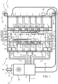
- reference numeral indicates an underwater hydrocarbon production facility.
- the facility 1 is arranged on a bed 2 of a body of water near a subsea well or well field, not shown in the accompanying figures, and comprises a cluster 3, which comprises a plurality of functional modules 4, 5, 6 and 7 configured to process hydrocarbons, and an interconnection unit 8 configured for being arranged on the bed 2 of the body of water to connect the functional modules 4, 5, 6 and 7 to each other.
- Each of the functional modules 4, 5, 6 and 7 comprises a plurality of connection elements 9, while the interconnection unit 8 comprises a plurality of connection elements 10, each configured for being operatively connected to a corresponding connection element 9 of one of the functional modules 4, 5, 6 and 7.
- each of the functional modules 4, 5, 6 and 7 houses a respective apparatus for processing hydrocarbons or for performing operations related to hydrocarbon processing.
- apparatus is used to indicate: multiphase pump (function: multiphase pumping), liquid pump, gas compression, liquid/liquid separator, gas/liquid separator, solid/water separator, heat exchanger, water injection pump, chemical injection system, gas treatment system, oil treatment system, and water treatment system.
- the interconnection unit 8 comprises further connection elements 10 for connecting the inlet pipelines 11 and another two connection elements 10 for connecting to two respective outlet pipelines 12 that run to respective headers (not shown in the accompanying figures).
- connection elements 10 are interconnected by tubes, which are not shown in Figure 1 and are housed in the interconnection unit 8, for transferring process fluids between the functional modules 4, 5, 6 and 7, the inlet pipelines 11 and the outlet pipelines 12, according to a certain layout.
- the interconnection unit 8 also comprises valves, which are not shown in Figure 1 and are housed inside the interconnection unit 8, for regulating the flow of the process fluids.
- the interconnection unit 8 is configured to collect and distribute signals, electric power, chemical products and hydraulic fluids to and from the functional modules 4, 5, 6 and 7.
- the interconnection unit 8 comprises a control bus 13 and a plurality of tubes 14 for conveying chemical products and/or hydraulic fluids.
- the facility comprises a platform 15 on which the interconnection unit 8, the functional modules 4, 5, 6 and 7, two junction boxes 16, and two distribution units 17 rest.
- Signals, chemical products, hydraulic fluids and electric power are conveyed through an umbilical cable 18 and a switching unit 19, which distributes electric power directly through power cables 20 to modules 4 and 6, which house pumps or compressors.
- the switching unit 19 is connected to the two junction boxes 16 via a control bus 21 and a tube bundle 22 for hydraulic fluids, and to the chemical product distribution units 17 by a tube bundle 22.
- the junction boxes 16 and the chemical product distribution units 17 are in turn connected to the interconnection unit 8.
- the interconnection unit 8 shown in Figure 1 comprises two junction boxes 23, and two underwater control devices 24 that, in the case shown, are associated with the respective junction boxes 23 and are configured to process signals acquired from the functional modules 4, 5, 6 and 7, to emit control signals for controlling the functional modules 4, 5, 6 and 7, and to open and close the valves, not shown in the accompanying figures.
- Each of the functional modules 4, 5, 6 and 7 comprises an underwater control device 24 for controlling the parameters related to the associated process.
- each of the underwater control devices 24 of the interconnection unit 8 has the master function and is connected to all of the underwater control devices 24, which are installed in the functional modules 4, 5, 6 and 7 and have the slave function.
- the control system of the underwater facility 1 has a distributed-node architecture and comprises a distributed-node network comprising the control buses 13 and 21, and the junction boxes 16 and 23.
- the network connects the functional modules 4, 5, 6 and 7, or rather the underwater control devices 24 associated with the respective functional modules 4, 5, 6 and 7, and the switching unit 19 that, in turn, is connected to a surface control unit, not shown in the accompanying figures.
- Each underwater control device 24 is placed at a respective node of the network to isolate the respective functional module 4 or 5 or 6 or 7 from the control network.
- the master control devices 24 are placed at other points of the control network, but conveniently inside the interconnection module 8.
- the underwater facility 1 is integrated by a maintenance and inspection system 25, which, in the case shown, comprises a base station 26, an unmanned underwater vehicle 27, and two communication stations 28, the need for which or the number of which is based on the size and the configuration of the facility 1.
- the base station 26 is adjacent to the switching unit 19 and is connected to the umbilical cable 18 from which it receives power and through which it exchanges signals with a surface station, not shown in the accompanying figures.
- the base station 26 has the function of housing the underwater vehicle 27 and of performing service operations on the underwater vehicle 27.
- the communication stations 28 are placed in the areas furthest away from the base station 26.
- the unmanned underwater vehicle 27 has a longitudinal axis A and comprises a frame 29, at least one buoy 30, with variable trim if necessary, and a plurality of thrusters 31, which together define the navigation devices of the underwater vehicle 27.
- the underwater vehicle 27 comprises at least one power accumulator 32, and a control unit 33 so as to define control and minimum autonomy for the underwater vehicle 27.
- the underwater vehicle 27 comprises navigation sensors, which include a gyrocompass 34, a speed sensor 35, accelerometers 36, acoustic positioning systems 37, and an obstacle avoidance system 38 of the acoustic or electromagnetic type, which allow navigating by instrument in complex scenarios.
- navigation sensors include a gyrocompass 34, a speed sensor 35, accelerometers 36, acoustic positioning systems 37, and an obstacle avoidance system 38 of the acoustic or electromagnetic type, which allow navigating by instrument in complex scenarios.
- the buoy 30 basically defines the upper part of the underwater vehicle 27, while the frame 29 in the lower part of the underwater vehicle 27 supports two interfaces 39 and 40.
- the two interfaces 39 and 40 are perpendicular to the longitudinal axis A of the underwater vehicle 27 and define two opposite faces of the lower part of the underwater vehicle 27.
- the system 25 in Figure 1 also comprises a plurality of operational modules 41, 42 and 43 ( Figures 3, 4 and 5 , respectively), each of which is configured to be coupled to the underwater vehicle 27 on interface 39, and a plurality of power and communication modules 44, 45 and 46 ( Figures 6, 7 and 8 respectively), each of which is configured to be coupled to the underwater vehicle 27 on interface 40.
- the operational modules 41, 42 and 43 comprise a manipulator module 41 ( Figure 3 ), at least one tool module 42 ( Figure 4 ), and at least one inspection module ( Figure 5 ).
- the manipulator module 41 comprises a support structure 47, a manipulator arm 48, especially of the electric type and mounted on the support structure 47, and an interface 49 that defines a face of the support structure 47 and is configured for being connected to interface 39.
- the manipulator module 41 has the task of performing operations that require the manipulation of objects with a high level of precision and relatively small forces.
- the tool module 42 comprises a support structure 50, a tool 51 mounted on the support structure 50, a power actuator 52 mounted on the support structure 50 to operate the tool 51, and an interface 53 that defines a face of the support structure 50 and is configured for being connected to interface 39 of the underwater vehicle 27.
- the tool module 42 has the task of performing operations that require the use of high force or supplying fluid at high pressure (for example, to carry out sealing tests or water injections from a nozzle).
- the term "tool” identifies both the actual tool, for example a screwdriver, and an apparatus for supplying pressure/flow to the underwater facility, e.g. for sealing tests or for operating valves.
- the inspection module 43 comprises a support structure 54, one or more probes 55 mounted on the support structure 54, and an interface 56 that defines a face of the support structure 54 and is configured for being connected to interface 39 of the underwater vehicle 27.
- the inspection module 43 has the task of performing inspection operations on the facility 1 ( Figure 1 ).
- the power and communication module 44 comprises a power supply block 57, a power and data transmission cable 58 connected to the power supply block 57, and an interface 59 that defines a face of the power supply block 57.
- the power and communication module 44 enables infinite operating autonomy, wide range, and real-time data transmission, but has the drawback of requiring a cable 58 of relatively large dimensions that, in some operations, can become a hindrance and impair the manoeuvrability of the underwater vehicle 27.
- the power and communication module 45 comprises a battery block 60, a transceiver 61 for data transmission connected to the battery block 60, and an interface 62 that defines a face of the battery block 60.
- the power and communication module 45 enables limited operating autonomy and a relatively limited real-time data transmission capability, but the absence of a cable ensures excellent manoeuvrability for the underwater vehicle 27.
- the power and communication module 46 comprises a battery block 63, a data cable 64 for data transmission only and connected to the battery block 63, and an interface 65 that defines a face of the battery block 63.
- the power and communication module 46 enables limited operating autonomy, wide range, and a real-time data transmission capability.
- a small-sized cable for only data transmission does not excessively hinder and defines an intermediate manoeuvrability condition for the underwater vehicle 27 with respect to those described with reference to Figures 6 and 7 .
- the underwater vehicle 27 can assume various configurations, some of which are shown in Figures 9 to 11 , based on the possible combinations of operational modules 41, 42 and 43 in Figures 3 to 6 and power and communication modules 44, 45 and 46 in Figures 6 to 8 .
- the couplings between the underwater vehicle 27 and the operational modules 41, 42 and 43, and power and communication modules 44, 45 and 46 envisage structural couplings of a mechanical type and functional couplings of an electrical type.
- functional electrical couplings are preferably inductive electrical couplings.
- the operational modules 41, 42 and 43 in use, are powered by the power and communication module 44, 45 or 46 coupled to the underwater vehicle 27, but are set up for being independently powered.
- the base station 26 is configured to define the shelter for the underwater vehicle 27, the operational modules 41, 42 and 43 and the power and communication modules 44, 45 and 46.
- the base station 26 has parking stations 66, which are also configured for recharging batteries where necessary.
- the parking stations 66 are arranged in various points of the underwater facility 1 as shown, for example, by broken lines in Figure 1 .
- the base station 26 handles communications with the underwater vehicle 27 and is connected by the umbilical cable 18 to a surface control unit, not shown in the accompanying figures.
- the base station can comprise an umbilical cable for the supply of power and data transmission with the surface or with other underwater systems.
- the base station 26 is able to communicate with the underwater vehicle 27 both in cable mode, thanks to the parking station 66, and in wireless mode.
- Wireless communications are of the hybrid type and comprise acoustic, optical and electromagnetic types of communication.
- Acoustic communications can be disturbed by the morphology of the bed of the body of water and the structure of the underwater facility, optical communications can be compromised by poor visibility in the body of water, and electromagnetic communications in a body of water are only effective over a short range.
- the base station 26 and the underwater vehicle 27 communicate wirelessly with a hybrid system that provides for simultaneously exchanging data with optical, acoustic and electromagnetic communications.
- the communication stations 28 in Figure 1 are configured to transmit and receive data in the same manner as the base station 26 and, in fact, are repeaters of the base station 26.
- the base station 26 is also configured to perform the washing of the underwater vehicle 27, the operational modules 41, 42 and 43 and the power and communication modules 44, 45 and 46.
- the base station 26 comprises a cleaning device 67, which is configured to emit water jets, and comprises brushes 68 for removing any fouling that might form following prolonged permanence in the body of water.
- the cleaning station 67 can also comprise UV radiation generators and/or chemical products and/or ultrasonic generators.
- the maintenance and inspection system is associated with an underwater hydrocarbon production facility, but the claimed vehicle and system may obviously find other applications in an underwater environment.
- the system can comprise more than one unmanned vehicle and/or more base stations, with the number of unmanned underwater vehicles and base stations depending on the size and complexity of the facility.
Landscapes
- Engineering & Computer Science (AREA)
- Mechanical Engineering (AREA)
- Aviation & Aerospace Engineering (AREA)
- Ocean & Marine Engineering (AREA)
- Control Of Position, Course, Altitude, Or Attitude Of Moving Bodies (AREA)
- Testing Or Calibration Of Command Recording Devices (AREA)
- Monitoring And Testing Of Nuclear Reactors (AREA)
Claims (21)
- Unbemanntes Unterwasserfahrzeug zur Instandhaltung und Inspektion von festen Unterwasseranlagen, wobei das Unterwasserfahrzeug (27) Folgendes umfasst:einen Rahmen (29); mindestens einen Schwimmkörper (30); eine Vielzahl von Strahlrudern (31); mindestens einen Stromspeicher (32); und eine Steuereinheit (33);wobei der Schwimmkörper (30) den oberen Teil des Unterwasserfahrzeugs (27) definiert, während der Rahmen (29) in dem unteren Teil des Unterwasserfahrzeugs (27) eine erste externe Schnittstelle (39) und eine zweite externe Schnittstelle (40) trägt;wobei die erste Schnittstelle (39) ausgestaltet ist, mechanisch und elektrisch mit einer Schnittstelle (49) eines auswechselbaren Betriebsmoduls (41; 42; 43) gekoppelt zu werden, das auf der Grundlage von spezifischen Anforderungen aus einer Vielzahl von auswechselbaren Betriebsmodulen (41; 42; 43) mit unterschiedlichen Eigenschaften ausgewählt wird; und wobei die zweite Schnittstelle (40) ausgestaltet ist, mechanisch und elektrisch mit einer Schnittstelle (59) eines auswechselbaren Stromversorgungs- und Kommunikationsmoduls (44; 45; 46) gekoppelt zu werden, das auf der Grundlage von spezifischen Anforderungen aus einer Vielzahl von auswechselbaren Stromversorgungs- und Kommunikationsmodulen (44; 45; 46) mit unterschiedlichen Eigenschaften ausgewählt wird;und wobei das auswechselbare Betriebsmodul (41; 42; 43), in Verwendung, von dem Stromversorgungs- und Kommunikationsmodul (44; 45; 46) elektrisch mit Strom versorgt wird, wenn beide Module jeweils mittels ihrer jeweiligen Schnittstellen (39, 40, 49, 59) mit dem Unterwasserfahrzeug (27) gekoppelt sind.
- Unterwasserfahrzeug nach Anspruch 1, wobei die erste und die zweite Schnittstelle (39, 40) funktionell miteinander verbunden sind, sodass sie gemeinsam Strom und Signale übertragen.
- Unterwasserfahrzeug nach einem beliebigen der vorhergehenden Ansprüche, und Navigationssensoren umfassend, insbesondere einen Kreiselkompass (34), einen Geschwindigkeitssensor (35), Beschleunigungsmesser (36), akustische Ortungssysteme (37) und ein Hindernisvermeidungssystem (38).
- System zur Instandhaltung und Inspektion von festen Unterwasseranlagen, das System (25) umfassend mindestens ein Unterwasserfahrzeug (27) nach einem beliebigen der vorhergehenden Ansprüche, eine Vielzahl von auswechselbaren Betriebsmodulen (41, 42, 43) mit unterschiedlichen Eigenschaften, wobei jedes auswechselbare Betriebsmodul eine Tragstruktur (47, 50, 54) und eine Schnittstelle, die eine Fläche der Tragstruktur (47, 50, 54) definiert und ausgestaltet ist, mit der ersten Schnittstelle (39) des Unterwasserfahrzeugs (27) verbunden zu werden, umfasst, und eine Vielzahl von auswechselbaren Stromversorgungs- und Kommunikationsmodulen (44, 45, 46) mit unterschiedlichen Eigenschaften, wobei jedes auswechselbare Stromversorgungs- und Kommunikationsmodul einen Stromzuführungsblock (57) oder einen Batterieblock (60, 63) und eine Schnittstelle umfasst, die eine Fläche des Stromversorgungs- oder Batterieblocks (57, 60, 63) definiert und ausgestaltet ist, mit der zweiten Schnittstelle (40) des Unterwasserfahrzeugs (27) verbunden zu werden.
- System nach Anspruch 4, wobei die Vielzahl von Betriebsmodulen mindestens ein Manipulatorbetriebsmodul (41), mindestens ein Werkzeugbetriebsmodul (42) und mindestens ein Inspektionsbetriebsmodul (43) umfasst.
- System nach Anspruch 5, wobei das Manipulatorbetriebsmodul (41) einen vorzugsweise elektrisch angetriebenen Manipulatorarm (48) und eine dritte Schnittstelle (49) umfasst, die zur strukturellen und funktionellen Kopplung mit der ersten Schnittstelle (39) des Unterwasserfahrzeugs (27) ausgestaltet ist.
- System nach Anspruch 5, wobei das Werkzeugbetriebsmodul (42) ein Werkzeug (51), einen jeweiligen Aktuator (52) und eine vierte Schnittstelle (53) umfasst, die zur strukturellen und funktionellen Kopplung mit der ersten Schnittstelle (39) des Unterwasserfahrzeugs (27) ausgestaltet ist.
- System nach Anspruch 5, wobei das Inspektionsbetriebsmodul (43) mindestens eine Sonde (55) und eine fünfte Schnittstelle (56) umfasst, die zur strukturellen und funktionellen Kopplung mit der ersten Schnittstelle (39) des Unterwasserfahrzeugs (27) ausgestaltet ist.
- System nach einem beliebigen der Ansprüche 4 bis 8, wobei die Vielzahl von Stromversorgungs- und Kommunikationsmodulen ein Kabelstromversorgungs- und Kabelkommunikationsmodul (44), ein Batteriestromversorgungs- und Drahtloskommunikationsmodul (45) und ein Batteriestromversorgungs- und Kabelkommunikationsmodul (46) umfasst.
- System nach Anspruch 9, wobei das Kabelstromversorgungs- und Kabelkommunikationsmodul (44) einen Stromzuführungsblock (57), ein Kabel zur Stromversorgung und Datenübertragung (58) und eine sechste Schnittstelle umfasst, die zur strukturellen und funktionellen Kopplung mit der zweiten Schnittstelle (40) des Unterwasserfahrzeugs (27) ausgestaltet ist.
- System nach Anspruch 9, wobei das Batteriestromversorgungs- und Drahtloskommunikationsmodul (45) einen Batterieblock (60), einen Sendeempfänger (61) und eine siebte Schnittstelle (62) umfasst, die zur strukturellen und funktionellen Kopplung mit der zweiten Schnittstelle (40) des Unterwasserfahrzeugs (27) ausgestaltet ist.
- System nach Anspruch 9, wobei das Batteriestromversorgungs- und Kabelkommunikationsmodul (46) einen Batterieblock (63), ein Datenkabel (64) und eine achte Schnittstelle (65) umfasst, die zur strukturellen und funktionellen Kopplung mit der zweiten Schnittstelle (40) des Unterwasserfahrzeugs (27) ausgestaltet ist.
- System nach einem beliebigen der Ansprüche 4 bis 12, wobei jedes Betriebsmodul (41, 42, 43) so ausgestaltet ist, dass es unabhängig von dem Unterwasserfahrzeug (27) mit Strom versorgt wird.
- System nach einem beliebigen der Ansprüche 4 bis 13, wobei jedes Betriebsmodul (41, 42, 43) durch das Unterwasserfahrzeug (27) von einem der Stromversorgungs- und Kommunikationsmodule (44, 45, 46) mit Strom versorgt wird.
- System nach einem beliebigen der Ansprüche 4 bis 14, und mindestens eine Basisstation (26) umfassend, die zur Aufnahme des Unterwasserfahrzeugs (27), der Betriebsmodule (41, 42, 43) und der Stromversorgungs- und Kommunikationsmodule (44, 45, 46) ausgestaltet ist.
- System nach Anspruch 15, und Parkstationen (66) umfassend, die zum Wiederaufladen der Batterien, soweit erforderlich, ausgestaltet sind.
- System nach Anspruch 15 oder 16, wobei die Basisstation (26) Kabel- und Drahtloskommunikationssysteme zum Kommunizieren mit dem Unterwasserfahrzeug (27) umfasst.
- System nach Anspruch 17, und mindestens eine Kommunikationsstation (28) umfassend, die zum Zwischenverstärken des Drahtlossignals der Basisstation (26) ausgestaltet ist.
- System nach einem beliebigen der Ansprüche 15 bis 18, wobei die Basisstation (26) eine Reinigungsvorrichtung (67) für das Unterwasserfahrzeug (27), die Vielzahl von Betriebsmodulen (41, 42, 43) und die Vielzahl von Stromversorgungs- und Kommunikationsmodulen (44, 45, 46) umfasst, wobei die Reinigungsvorrichtung (67) vorzugsweise zum Sprühen von Druckwasserstrahlen und/oder UV-Strahlung und/oder chemischen Produkten ausgestaltet ist und/oder Bürsten (69) zum Entfernen von Verschmutzungen und/oder Ultraschallgeneratoren umfasst.
- System nach einem beliebigen der Ansprüche 4 bis 19, wobei die Unterwasseranlage (1) zur Kohlenwasserstoffgewinnung verwendet wird.
- Verfahren zur Instandhaltung und Inspektion von festen Unterwasseranlagen mittels eines Unterwasserfahrzeugs, das einen Rahmen (29); mindestens einen Schwimmkörper (30); eine Vielzahl von Strahlrudern (31); mindestens einen Stromspeicher (32); und eine Steuereinheit (33) umfasst, wobei der Schwimmkörper (30) den oberen Teil des Unterwasserfahrzeugs (27) definiert, während der Rahmen (29) in dem unteren Teil des Unterwasserfahrzeugs (27) eine erste externe Schnittstelle (39) und eine zweite externe Schnittstelle (40) trägt; wobei das Verfahren folgende Schritte umfasst: mechanisches und elektrisches Koppeln der ersten Schnittstelle (39) mit einer Schnittstelle (49) eines auswechselbaren Betriebsmoduls (41; 42; 43), das auf der Grundlage von spezifischen Anforderungen aus einer Vielzahl von auswechselbaren Betriebsmodulen (41; 42; 43) mit unterschiedlichen Eigenschaften ausgewählt wird; mechanisches und elektrisches Koppeln der zweiten Schnittstelle (40) mit einer Schnittstelle (59) eines auswechselbaren Stromversorgungs- und Kommunikationsmoduls (44; 45; 46), das auf der Grundlage von spezifischen Anforderungen aus einer Vielzahl von auswechselbaren Stromversorgungs- und Kommunikationsmodulen (44, 45, 46) mit unterschiedlichen Eigenschaften ausgewählt wird; und elektrisches Versorgen des auswechselbaren Betriebsmoduls (41; 42; 43) mittels des Stromversorgungs- und Kommunikationsmoduls (44, 45, 46) mit Strom, wenn beide Module jeweils mittels ihrer jeweiligen Schnittstellen (39, 40, 49, 59) mit dem Unterwasserfahrzeug (27) gekoppelt sind.
Applications Claiming Priority (3)
| Application Number | Priority Date | Filing Date | Title |
|---|---|---|---|
| ITUA2016A001587A ITUA20161587A1 (it) | 2016-03-11 | 2016-03-11 | Veicolo subacqueo senza equipaggio, sistema e metodo per la manutenzione e l'ispezione di impianti subacquei |
| EP17719912.2A EP3426551B1 (de) | 2016-03-11 | 2017-03-10 | Unbemanntes unterwasserfahrzeug, system und verfahren zur instandhaltung und inspektion von unterwasseranlagen |
| PCT/IB2017/051423 WO2017153966A1 (en) | 2016-03-11 | 2017-03-10 | Unmanned underwater vehicle, system and method for the maintenance and inspection of underwater facilities |
Related Parent Applications (1)
| Application Number | Title | Priority Date | Filing Date |
|---|---|---|---|
| EP17719912.2A Division EP3426551B1 (de) | 2016-03-11 | 2017-03-10 | Unbemanntes unterwasserfahrzeug, system und verfahren zur instandhaltung und inspektion von unterwasseranlagen |
Publications (2)
| Publication Number | Publication Date |
|---|---|
| EP3670321A1 EP3670321A1 (de) | 2020-06-24 |
| EP3670321B1 true EP3670321B1 (de) | 2023-05-03 |
Family
ID=56203651
Family Applications (2)
| Application Number | Title | Priority Date | Filing Date |
|---|---|---|---|
| EP17719912.2A Active EP3426551B1 (de) | 2016-03-11 | 2017-03-10 | Unbemanntes unterwasserfahrzeug, system und verfahren zur instandhaltung und inspektion von unterwasseranlagen |
| EP20155064.7A Active EP3670321B1 (de) | 2016-03-11 | 2017-03-10 | Unbemanntes unterwasserfahrzeug, system und verfahren zur instandhaltung und inspektion von unterwasseranlagen |
Family Applications Before (1)
| Application Number | Title | Priority Date | Filing Date |
|---|---|---|---|
| EP17719912.2A Active EP3426551B1 (de) | 2016-03-11 | 2017-03-10 | Unbemanntes unterwasserfahrzeug, system und verfahren zur instandhaltung und inspektion von unterwasseranlagen |
Country Status (6)
| Country | Link |
|---|---|
| US (1) | US10604221B2 (de) |
| EP (2) | EP3426551B1 (de) |
| AU (1) | AU2017231035B2 (de) |
| BR (1) | BR112018068367B1 (de) |
| IT (1) | ITUA20161587A1 (de) |
| WO (1) | WO2017153966A1 (de) |
Families Citing this family (16)
| Publication number | Priority date | Publication date | Assignee | Title |
|---|---|---|---|---|
| WO2018204742A1 (en) | 2017-05-04 | 2018-11-08 | 3D at Depth, Inc. | Systems and methods for monitoring underwater structures |
| CA3069305A1 (en) | 2017-07-10 | 2019-01-17 | 3D at Depth, Inc. | Underwater optical positioning systems and methods |
| US11440626B2 (en) | 2017-12-18 | 2022-09-13 | Saipem S.P.A. | System and method for power and data transmission in a body of water to unmanned underwater vehicles |
| US11530018B2 (en) * | 2018-02-28 | 2022-12-20 | Oceaneering International, Inc. | Subsea inspection vehicle |
| JP7068060B2 (ja) * | 2018-06-15 | 2022-05-16 | 川崎重工業株式会社 | 水中給電システム |
| CN111290343A (zh) * | 2018-12-07 | 2020-06-16 | 中国科学院沈阳自动化研究所 | 水下机器人舱内总线式电气控制系统及方法 |
| IT201900006068A1 (it) * | 2019-04-18 | 2020-10-18 | Saipem Spa | Gruppo e metodo di campionamento e misura di fluidi |
| NL2024690B1 (en) * | 2020-01-17 | 2021-09-08 | Fnv Ip Bv | Underwater vehicle docking and communication |
| AR121398A1 (es) * | 2020-02-24 | 2022-06-01 | California Inst Of Techn | Sensor de composición infrarrojo basado en absorción para mezclas de fluidos |
| CN111186542A (zh) * | 2020-03-04 | 2020-05-22 | 广东海洋大学 | 一种水下作业机器人 |
| WO2022067194A2 (en) | 2020-09-25 | 2022-03-31 | 3D at Depth, Inc. | Systems and methods for laser inspection and measurements |
| IT202000028079A1 (it) | 2020-11-23 | 2022-05-23 | Saipem Spa | Veicolo subacqueo senza equipaggio e sistema per la manutenzione e l'ispezione di impianti subacquei e metodo di gestione di un cavo per alimentare energia e controllare detto veicolo subacqueo |
| RU2770623C1 (ru) * | 2021-02-04 | 2022-04-19 | Федеральное государственное казенное военное образовательное учреждение высшего образования "Военный учебно-научный центр Военно-Морского Флота "Военно-морская академия им. Адмирала Флота Советского Союза Н.Г. Кузнецова" | Составной автономный необитаемый подводный аппарат |
| CN113844627A (zh) * | 2021-10-22 | 2021-12-28 | 杭州电子科技大学 | 一种水下无人无缆作业型机器人 |
| IL293052B2 (en) * | 2022-05-16 | 2024-01-01 | Maytronics Ltd | Pool related platform and added-on accessories |
| WO2025115022A1 (en) * | 2023-11-28 | 2025-06-05 | Shabat Matan | Water vehicle system |
Family Cites Families (9)
| Publication number | Priority date | Publication date | Assignee | Title |
|---|---|---|---|---|
| US6390012B1 (en) | 1999-09-20 | 2002-05-21 | Coflexip, S.A. | Apparatus and method for deploying, recovering, servicing, and operating an autonomous underwater vehicle |
| GB9927624D0 (en) * | 1999-11-24 | 2000-01-19 | Slingsby Engineering Ltd | Remotely controlled submersible vehicle for subsea tooling |
| US6808021B2 (en) | 2000-08-14 | 2004-10-26 | Schlumberger Technology Corporation | Subsea intervention system |
| US8082870B2 (en) * | 2008-02-25 | 2011-12-27 | University Of Southern California | Multiplex-thruster systems for delivering thrusting flow |
| TWI422416B (zh) * | 2011-05-24 | 2014-01-11 | 國立暨南國際大學 | Waterborne mechanical organisms and their systems |
| DE102011107824A1 (de) * | 2011-07-16 | 2013-01-17 | Atlas Elektronik Gmbh | Einrichtung und Verfahren zum Betreiben eines unbemannten Unterwasserfahrzeugs sowie Unterwasserfahrzeug mit der Einrichtung |
| WO2015061600A1 (en) | 2013-10-23 | 2015-04-30 | Oceaneering International, Inc. | A remotely operated vehicle integrated system |
| GB2521626C (en) * | 2013-12-23 | 2019-10-30 | Subsea 7 Ltd | Transmission of power underwater |
| GB2523388B (en) | 2014-02-24 | 2016-12-07 | Subsea 7 Ltd | Subsea hosting of unmanned underwater vehicles |
-
2016
- 2016-03-11 IT ITUA2016A001587A patent/ITUA20161587A1/it unknown
-
2017
- 2017-03-10 US US16/082,439 patent/US10604221B2/en active Active
- 2017-03-10 EP EP17719912.2A patent/EP3426551B1/de active Active
- 2017-03-10 EP EP20155064.7A patent/EP3670321B1/de active Active
- 2017-03-10 BR BR112018068367-1A patent/BR112018068367B1/pt active IP Right Grant
- 2017-03-10 AU AU2017231035A patent/AU2017231035B2/en active Active
- 2017-03-10 WO PCT/IB2017/051423 patent/WO2017153966A1/en not_active Ceased
Also Published As
| Publication number | Publication date |
|---|---|
| US20190084658A1 (en) | 2019-03-21 |
| WO2017153966A1 (en) | 2017-09-14 |
| BR112018068367B1 (pt) | 2023-10-03 |
| EP3426551A1 (de) | 2019-01-16 |
| BR112018068367A2 (pt) | 2019-01-15 |
| EP3426551B1 (de) | 2020-02-26 |
| ITUA20161587A1 (it) | 2017-09-11 |
| AU2017231035B2 (en) | 2021-11-04 |
| US10604221B2 (en) | 2020-03-31 |
| AU2017231035A1 (en) | 2018-09-13 |
| EP3670321A1 (de) | 2020-06-24 |
Similar Documents
| Publication | Publication Date | Title |
|---|---|---|
| EP3670321B1 (de) | Unbemanntes unterwasserfahrzeug, system und verfahren zur instandhaltung und inspektion von unterwasseranlagen | |
| US9944370B2 (en) | Subsea hosting of unmanned underwater vehicles | |
| EP3279429B1 (de) | Modularer verteiler | |
| US10727954B2 (en) | Long distance subsea can bus distribution system | |
| CN109716004B (zh) | 协调型水环境移动机器人 | |
| US20170204704A1 (en) | Remotely-Operated Subsea Control Module | |
| EP3220585B1 (de) | System und verfahren für unterwasser optisch-zu-elektrisch-verteilung | |
| US20160186534A1 (en) | Subsea system comprising a crawler | |
| WO2016125114A1 (en) | Underwater hydrocarbon processing facility | |
| EP3165709B1 (de) | Geteiltes betätigungssystem | |
| OA18842A (en) | Unmanned underwater vehicle, system and method for the maintenance and inspection of underwater facilities. | |
| EP3343022B1 (de) | Unterwasser-stromerzeugungssystem | |
| EP3429918B1 (de) | Wiederaufladbare autonome rovs mit einer offshore-stromquelle | |
| EP3956546B1 (de) | Anordnung und verfahren zur entnahme und messung einer flüssigkeit | |
| US12606285B2 (en) | Unmanned underwater vehicle and system for the maintenance and inspection of underwater facilities and method of managing a tether to supply power and to control said underwater vehicle | |
| US20260054809A1 (en) | Pipe anchoring system and device for autonomous in-fluid robotic device | |
| WO2016062658A1 (en) | Apparatus for performing operations in a pipeline and corresponding method |
Legal Events
| Date | Code | Title | Description |
|---|---|---|---|
| PUAI | Public reference made under article 153(3) epc to a published international application that has entered the european phase |
Free format text: ORIGINAL CODE: 0009012 |
|
| STAA | Information on the status of an ep patent application or granted ep patent |
Free format text: STATUS: THE APPLICATION HAS BEEN PUBLISHED |
|
| AC | Divisional application: reference to earlier application |
Ref document number: 3426551 Country of ref document: EP Kind code of ref document: P |
|
| AK | Designated contracting states |
Kind code of ref document: A1 Designated state(s): AL AT BE BG CH CY CZ DE DK EE ES FI FR GB GR HR HU IE IS IT LI LT LU LV MC MK MT NL NO PL PT RO RS SE SI SK SM TR |
|
| STAA | Information on the status of an ep patent application or granted ep patent |
Free format text: STATUS: REQUEST FOR EXAMINATION WAS MADE |
|
| 17P | Request for examination filed |
Effective date: 20201223 |
|
| RBV | Designated contracting states (corrected) |
Designated state(s): AL AT BE BG CH CY CZ DE DK EE ES FI FR GB GR HR HU IE IS IT LI LT LU LV MC MK MT NL NO PL PT RO RS SE SI SK SM TR |
|
| STAA | Information on the status of an ep patent application or granted ep patent |
Free format text: STATUS: EXAMINATION IS IN PROGRESS |
|
| 17Q | First examination report despatched |
Effective date: 20210609 |
|
| GRAP | Despatch of communication of intention to grant a patent |
Free format text: ORIGINAL CODE: EPIDOSNIGR1 |
|
| STAA | Information on the status of an ep patent application or granted ep patent |
Free format text: STATUS: GRANT OF PATENT IS INTENDED |
|
| INTG | Intention to grant announced |
Effective date: 20221020 |
|
| RAP3 | Party data changed (applicant data changed or rights of an application transferred) |
Owner name: SAIPEM S.P.A. |
|
| GRAS | Grant fee paid |
Free format text: ORIGINAL CODE: EPIDOSNIGR3 |
|
| GRAA | (expected) grant |
Free format text: ORIGINAL CODE: 0009210 |
|
| STAA | Information on the status of an ep patent application or granted ep patent |
Free format text: STATUS: THE PATENT HAS BEEN GRANTED |
|
| AC | Divisional application: reference to earlier application |
Ref document number: 3426551 Country of ref document: EP Kind code of ref document: P |
|
| AK | Designated contracting states |
Kind code of ref document: B1 Designated state(s): AL AT BE BG CH CY CZ DE DK EE ES FI FR GB GR HR HU IE IS IT LI LT LU LV MC MK MT NL NO PL PT RO RS SE SI SK SM TR |
|
| REG | Reference to a national code |
Ref country code: GB Ref legal event code: FG4D |
|
| REG | Reference to a national code |
Ref country code: DE Ref legal event code: R096 Ref document number: 602017068484 Country of ref document: DE |
|
| REG | Reference to a national code |
Ref country code: AT Ref legal event code: REF Ref document number: 1564378 Country of ref document: AT Kind code of ref document: T Effective date: 20230515 Ref country code: CH Ref legal event code: EP |
|
| REG | Reference to a national code |
Ref country code: IE Ref legal event code: FG4D |
|
| P01 | Opt-out of the competence of the unified patent court (upc) registered |
Effective date: 20230420 |
|
| REG | Reference to a national code |
Ref country code: NL Ref legal event code: FP |
|
| REG | Reference to a national code |
Ref country code: NO Ref legal event code: T2 Effective date: 20230503 |
|
| REG | Reference to a national code |
Ref country code: LT Ref legal event code: MG9D |
|
| REG | Reference to a national code |
Ref country code: AT Ref legal event code: MK05 Ref document number: 1564378 Country of ref document: AT Kind code of ref document: T Effective date: 20230503 |
|
| PG25 | Lapsed in a contracting state [announced via postgrant information from national office to epo] |
Ref country code: SE Free format text: LAPSE BECAUSE OF FAILURE TO SUBMIT A TRANSLATION OF THE DESCRIPTION OR TO PAY THE FEE WITHIN THE PRESCRIBED TIME-LIMIT Effective date: 20230503 Ref country code: PT Free format text: LAPSE BECAUSE OF FAILURE TO SUBMIT A TRANSLATION OF THE DESCRIPTION OR TO PAY THE FEE WITHIN THE PRESCRIBED TIME-LIMIT Effective date: 20230904 Ref country code: ES Free format text: LAPSE BECAUSE OF FAILURE TO SUBMIT A TRANSLATION OF THE DESCRIPTION OR TO PAY THE FEE WITHIN THE PRESCRIBED TIME-LIMIT Effective date: 20230503 Ref country code: AT Free format text: LAPSE BECAUSE OF FAILURE TO SUBMIT A TRANSLATION OF THE DESCRIPTION OR TO PAY THE FEE WITHIN THE PRESCRIBED TIME-LIMIT Effective date: 20230503 |
|
| PG25 | Lapsed in a contracting state [announced via postgrant information from national office to epo] |
Ref country code: RS Free format text: LAPSE BECAUSE OF FAILURE TO SUBMIT A TRANSLATION OF THE DESCRIPTION OR TO PAY THE FEE WITHIN THE PRESCRIBED TIME-LIMIT Effective date: 20230503 Ref country code: PL Free format text: LAPSE BECAUSE OF FAILURE TO SUBMIT A TRANSLATION OF THE DESCRIPTION OR TO PAY THE FEE WITHIN THE PRESCRIBED TIME-LIMIT Effective date: 20230503 Ref country code: LV Free format text: LAPSE BECAUSE OF FAILURE TO SUBMIT A TRANSLATION OF THE DESCRIPTION OR TO PAY THE FEE WITHIN THE PRESCRIBED TIME-LIMIT Effective date: 20230503 Ref country code: LT Free format text: LAPSE BECAUSE OF FAILURE TO SUBMIT A TRANSLATION OF THE DESCRIPTION OR TO PAY THE FEE WITHIN THE PRESCRIBED TIME-LIMIT Effective date: 20230503 Ref country code: IS Free format text: LAPSE BECAUSE OF FAILURE TO SUBMIT A TRANSLATION OF THE DESCRIPTION OR TO PAY THE FEE WITHIN THE PRESCRIBED TIME-LIMIT Effective date: 20230903 Ref country code: HR Free format text: LAPSE BECAUSE OF FAILURE TO SUBMIT A TRANSLATION OF THE DESCRIPTION OR TO PAY THE FEE WITHIN THE PRESCRIBED TIME-LIMIT Effective date: 20230503 Ref country code: GR Free format text: LAPSE BECAUSE OF FAILURE TO SUBMIT A TRANSLATION OF THE DESCRIPTION OR TO PAY THE FEE WITHIN THE PRESCRIBED TIME-LIMIT Effective date: 20230804 |
|
| PG25 | Lapsed in a contracting state [announced via postgrant information from national office to epo] |
Ref country code: FI Free format text: LAPSE BECAUSE OF FAILURE TO SUBMIT A TRANSLATION OF THE DESCRIPTION OR TO PAY THE FEE WITHIN THE PRESCRIBED TIME-LIMIT Effective date: 20230503 |
|
| PG25 | Lapsed in a contracting state [announced via postgrant information from national office to epo] |
Ref country code: SK Free format text: LAPSE BECAUSE OF FAILURE TO SUBMIT A TRANSLATION OF THE DESCRIPTION OR TO PAY THE FEE WITHIN THE PRESCRIBED TIME-LIMIT Effective date: 20230503 |
|
| PG25 | Lapsed in a contracting state [announced via postgrant information from national office to epo] |
Ref country code: SM Free format text: LAPSE BECAUSE OF FAILURE TO SUBMIT A TRANSLATION OF THE DESCRIPTION OR TO PAY THE FEE WITHIN THE PRESCRIBED TIME-LIMIT Effective date: 20230503 Ref country code: SK Free format text: LAPSE BECAUSE OF FAILURE TO SUBMIT A TRANSLATION OF THE DESCRIPTION OR TO PAY THE FEE WITHIN THE PRESCRIBED TIME-LIMIT Effective date: 20230503 Ref country code: RO Free format text: LAPSE BECAUSE OF FAILURE TO SUBMIT A TRANSLATION OF THE DESCRIPTION OR TO PAY THE FEE WITHIN THE PRESCRIBED TIME-LIMIT Effective date: 20230503 Ref country code: EE Free format text: LAPSE BECAUSE OF FAILURE TO SUBMIT A TRANSLATION OF THE DESCRIPTION OR TO PAY THE FEE WITHIN THE PRESCRIBED TIME-LIMIT Effective date: 20230503 Ref country code: DK Free format text: LAPSE BECAUSE OF FAILURE TO SUBMIT A TRANSLATION OF THE DESCRIPTION OR TO PAY THE FEE WITHIN THE PRESCRIBED TIME-LIMIT Effective date: 20230503 Ref country code: CZ Free format text: LAPSE BECAUSE OF FAILURE TO SUBMIT A TRANSLATION OF THE DESCRIPTION OR TO PAY THE FEE WITHIN THE PRESCRIBED TIME-LIMIT Effective date: 20230503 |
|
| REG | Reference to a national code |
Ref country code: DE Ref legal event code: R097 Ref document number: 602017068484 Country of ref document: DE |
|
| PLBE | No opposition filed within time limit |
Free format text: ORIGINAL CODE: 0009261 |
|
| STAA | Information on the status of an ep patent application or granted ep patent |
Free format text: STATUS: NO OPPOSITION FILED WITHIN TIME LIMIT |
|
| 26N | No opposition filed |
Effective date: 20240206 |
|
| PG25 | Lapsed in a contracting state [announced via postgrant information from national office to epo] |
Ref country code: SI Free format text: LAPSE BECAUSE OF FAILURE TO SUBMIT A TRANSLATION OF THE DESCRIPTION OR TO PAY THE FEE WITHIN THE PRESCRIBED TIME-LIMIT Effective date: 20230503 |
|
| PG25 | Lapsed in a contracting state [announced via postgrant information from national office to epo] |
Ref country code: SI Free format text: LAPSE BECAUSE OF FAILURE TO SUBMIT A TRANSLATION OF THE DESCRIPTION OR TO PAY THE FEE WITHIN THE PRESCRIBED TIME-LIMIT Effective date: 20230503 |
|
| REG | Reference to a national code |
Ref country code: DE Ref legal event code: R119 Ref document number: 602017068484 Country of ref document: DE |
|
| REG | Reference to a national code |
Ref country code: CH Ref legal event code: PL |
|
| PG25 | Lapsed in a contracting state [announced via postgrant information from national office to epo] |
Ref country code: BG Free format text: LAPSE BECAUSE OF FAILURE TO SUBMIT A TRANSLATION OF THE DESCRIPTION OR TO PAY THE FEE WITHIN THE PRESCRIBED TIME-LIMIT Effective date: 20230503 |
|
| PG25 | Lapsed in a contracting state [announced via postgrant information from national office to epo] |
Ref country code: LU Free format text: LAPSE BECAUSE OF NON-PAYMENT OF DUE FEES Effective date: 20240310 |
|
| PG25 | Lapsed in a contracting state [announced via postgrant information from national office to epo] |
Ref country code: MC Free format text: LAPSE BECAUSE OF FAILURE TO SUBMIT A TRANSLATION OF THE DESCRIPTION OR TO PAY THE FEE WITHIN THE PRESCRIBED TIME-LIMIT Effective date: 20230503 |
|
| PG25 | Lapsed in a contracting state [announced via postgrant information from national office to epo] |
Ref country code: MC Free format text: LAPSE BECAUSE OF FAILURE TO SUBMIT A TRANSLATION OF THE DESCRIPTION OR TO PAY THE FEE WITHIN THE PRESCRIBED TIME-LIMIT Effective date: 20230503 Ref country code: LU Free format text: LAPSE BECAUSE OF NON-PAYMENT OF DUE FEES Effective date: 20240310 Ref country code: BG Free format text: LAPSE BECAUSE OF FAILURE TO SUBMIT A TRANSLATION OF THE DESCRIPTION OR TO PAY THE FEE WITHIN THE PRESCRIBED TIME-LIMIT Effective date: 20230503 |
|
| REG | Reference to a national code |
Ref country code: BE Ref legal event code: MM Effective date: 20240331 |
|
| PG25 | Lapsed in a contracting state [announced via postgrant information from national office to epo] |
Ref country code: DE Free format text: LAPSE BECAUSE OF NON-PAYMENT OF DUE FEES Effective date: 20241001 |
|
| PG25 | Lapsed in a contracting state [announced via postgrant information from national office to epo] |
Ref country code: BE Free format text: LAPSE BECAUSE OF NON-PAYMENT OF DUE FEES Effective date: 20240331 |
|
| PG25 | Lapsed in a contracting state [announced via postgrant information from national office to epo] |
Ref country code: IE Free format text: LAPSE BECAUSE OF NON-PAYMENT OF DUE FEES Effective date: 20240310 |
|
| PG25 | Lapsed in a contracting state [announced via postgrant information from national office to epo] |
Ref country code: IE Free format text: LAPSE BECAUSE OF NON-PAYMENT OF DUE FEES Effective date: 20240310 Ref country code: DE Free format text: LAPSE BECAUSE OF NON-PAYMENT OF DUE FEES Effective date: 20241001 Ref country code: BE Free format text: LAPSE BECAUSE OF NON-PAYMENT OF DUE FEES Effective date: 20240331 Ref country code: CH Free format text: LAPSE BECAUSE OF NON-PAYMENT OF DUE FEES Effective date: 20240331 |
|
| PG25 | Lapsed in a contracting state [announced via postgrant information from national office to epo] |
Ref country code: CY Free format text: LAPSE BECAUSE OF FAILURE TO SUBMIT A TRANSLATION OF THE DESCRIPTION OR TO PAY THE FEE WITHIN THE PRESCRIBED TIME-LIMIT; INVALID AB INITIO Effective date: 20170310 |
|
| PG25 | Lapsed in a contracting state [announced via postgrant information from national office to epo] |
Ref country code: HU Free format text: LAPSE BECAUSE OF FAILURE TO SUBMIT A TRANSLATION OF THE DESCRIPTION OR TO PAY THE FEE WITHIN THE PRESCRIBED TIME-LIMIT; INVALID AB INITIO Effective date: 20170310 |
|
| PG25 | Lapsed in a contracting state [announced via postgrant information from national office to epo] |
Ref country code: TR Free format text: LAPSE BECAUSE OF FAILURE TO SUBMIT A TRANSLATION OF THE DESCRIPTION OR TO PAY THE FEE WITHIN THE PRESCRIBED TIME-LIMIT Effective date: 20230503 |
|
| PGFP | Annual fee paid to national office [announced via postgrant information from national office to epo] |
Ref country code: GB Payment date: 20260323 Year of fee payment: 10 |
|
| PGFP | Annual fee paid to national office [announced via postgrant information from national office to epo] |
Ref country code: NO Payment date: 20260318 Year of fee payment: 10 |
|
| PGFP | Annual fee paid to national office [announced via postgrant information from national office to epo] |
Ref country code: IT Payment date: 20260320 Year of fee payment: 10 |
|
| PGFP | Annual fee paid to national office [announced via postgrant information from national office to epo] |
Ref country code: NL Payment date: 20260323 Year of fee payment: 10 |
|
| PGFP | Annual fee paid to national office [announced via postgrant information from national office to epo] |
Ref country code: FR Payment date: 20260323 Year of fee payment: 10 |