EP3670122A1 - Outil de poinçonnage mâle et dispositif de poinçonnage - Google Patents
Outil de poinçonnage mâle et dispositif de poinçonnage Download PDFInfo
- Publication number
- EP3670122A1 EP3670122A1 EP18215773.5A EP18215773A EP3670122A1 EP 3670122 A1 EP3670122 A1 EP 3670122A1 EP 18215773 A EP18215773 A EP 18215773A EP 3670122 A1 EP3670122 A1 EP 3670122A1
- Authority
- EP
- European Patent Office
- Prior art keywords
- punch
- punch tool
- male
- carton
- female die
- Prior art date
- Legal status (The legal status is an assumption and is not a legal conclusion. Google has not performed a legal analysis and makes no representation as to the accuracy of the status listed.)
- Withdrawn
Links
Images


Classifications
-
- B—PERFORMING OPERATIONS; TRANSPORTING
- B26—HAND CUTTING TOOLS; CUTTING; SEVERING
- B26F—PERFORATING; PUNCHING; CUTTING-OUT; STAMPING-OUT; SEVERING BY MEANS OTHER THAN CUTTING
- B26F1/00—Perforating; Punching; Cutting-out; Stamping-out; Apparatus therefor
- B26F1/02—Perforating by punching, e.g. with relatively-reciprocating punch and bed
- B26F1/06—Perforating by punching, e.g. with relatively-reciprocating punch and bed with punching tools moving with the work
- B26F1/08—Perforating by punching, e.g. with relatively-reciprocating punch and bed with punching tools moving with the work wherein the tools are carried by, and in operation move relative to, a rotative drum or similar support
Definitions
- the invention relates to a male punch tool, as well as to a punch device using such male punch tool.
- the invention also relates to a system for providing a carton-based layer with a pre-laminated hole, as well as a method for providing a carton-based layer with a pre-laminated hole.
- the present invention also relates to a packaging material being manufactured by such method.
- Today punch devices are used to provide holes in various kinds of materials. Within the packaging industry, such punch devices can be used to provide holes in a packaging material later forming individual packages. In liquid food packaging, such holes may typically be intended to be penetrated by a straw.
- the packaging material may be a carton-based material, i.e. the packaging material comprises a core layer of carton-based material being laminated with one or more polymer layers.
- the packaging material comprises a core layer of carton-based material being laminated with one or more polymer layers.
- a punch device comprises a male punch tool and a female die being aligned with the male punch tool.
- the carton-based layer is arranged between the male punch tool and the female die. Upon operation the male punch tool is pressed towards the female die thus cutting off a piece of the carton-based layer thereby forming a hole.
- this punching process is implemented using a rotary system, i.e. the male punch tool is provided on a first roller while the female die is provided on a second roller.
- the first and second rollers are rotating against each other and they are aligned and synchronized such that the male punch tool will always hit the female die during rotation.
- the male punch tool forms part of a punch device for providing pre-laminated holes in a carton-based packaging material.
- the male punch tool comprises a punch member being arranged within a punch tool body and allowed to move axially relative said punch tool body, wherein the punch member is at least to some extent prevented from rotating relative the punch tool body.
- the punch member is allowed to rotate relative the punch tool body by ⁇ 10° or less, such as by ⁇ 5° or less, such as by ⁇ 3° or less.
- the punch member may be provided with at least one chamfer truncating the circumference of a cylindrical portion of the punch member.
- the punch tool body may be provided with a mating chamfer to fit with the chamfer of the punch member.
- the punch member may be provided with a distal round surface.
- a punch device comprises a male punch tool according to the first aspect, and a female die during use configured to be aligned with the punch member of the male punch tool.
- a system for providing a carton-based layer with a pre-laminated hole comprises a punching roller being provided with at least one male punch tool according to the first aspect arranged at its circumference, and an anvil roller being provided with at least one female die.
- the diameter of the punching roller may be equal to the diameter of the anvil roller.
- a method for providing a carton-based layer of a packaging material with a pre-laminated hole comprises i) arranging the carton-based layer between a male punch tool and a female die, ii) moving the male punch tool and the female die towards each other such that the carton-based layer is clamped between the male punch tool and the female die, and iii) decreasing the distance between the male punch tool and the female die such that the carton-based layer is cut, whereby a punching member of the male punch tool is at least to some extent prevented from rotating relative a punch tool body.
- a packaging material is provided.
- the packaging material is manufactured by the method according to the fourth aspect.
- a portion package 10 is shown.
- the package 10 is formed by a carton-based packaging material 20' and it is provided with a pre-laminated opening hole 12, as well as a straw 14 being attached to the package 10 by means of a pouch 16.
- the shown package 10 is a brick-shaped package and contains typically 100-350 ml of liquid food product, whereby the product is accessible to a consumer by penetration of the hole 12, and insertion of the straw 14 into the hole 12.
- the opening hole 12 is pre-laminated, i.e. the hole 12 is provided in the carton-based layer prior to lamination.
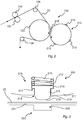
- FIG. 2 An example of a system 100 for providing a carton-based layer 20, later forming part of a packaging material 20', with a pre-laminated hole 12 is shown in Fig. 2 .
- the system 100 comprises a punching roller 110 having at least one male punch tool 210 attached to it; in Fig. 2 four male punch tools 210 are provided on the roller 110 however this number could be changed depending on the particular application.
- the roller 110 is configured to rotate against an anvil roller 120.
- the anvil roller 120 may have a rigid outer surface and one or more dies (not shown) arranged at the surface.
- a web of a carton-based layer 20 is fed through the system 100 via one or more guiding rollers 132, 134, 136, 138.
- the diameter of the anvil roller 120 may be equal, or close to the diameter of the punching roller 110.
- the part to be cut of the carton-based layer 20 should be substantially planar when the male punch tool 210 engages with the carton-based layer 20. Hence, as the punching roller 110 is rotating against the anvil roller 120 the male punch tool 210 will periodically come into contact with the carton-based layer 20, whereby a hole is cut out from the carton-based layer 20.
- the punching roller 110 may have several male punch tools 210. Hence holes having different dimensions may be cut in a continuous manner as the system 100 is operating.
- the male punch tools 210 may be distributed peripherally as well as axially on the punching roller 110; the female dies may be distributed correspondingly on the anvil roller 120.
- a punch device 200 is shown in further details in Figs. 3 and 4 .
- the punch device 200 comprises a male punch tool 210 and a female die 220; hence the system 100, configured to provide a carton-based layer 20 with a pre-laminated hole 12, comprises several punch devices 200.
- the punch device 200 may not necessarily be provided as a unit being constantly in operation; as understood from the description relating to Fig. 2 the punch devices 200 are provided when a male punch tool 210 meets a female die 220. During a revolution punch devices 200 will thereby be formed in a repetitive manner, the frequency depending on the rotational speed and the exact distribution of male punch tools 210 and female dies 220 along the periphery.
- Fig. 3 the cross-sectional view is exploded.
- the male punch tool 210 will engage with the female die 220 by a rotational movement, the respective axis of rotation being arranged at radial distances from the interface being substantially larger than the dimensions of the male punch tool 210 and/or the female die 220.
- the operational positioning of the male punch tool 210 in relation to the female die 220 is correctly represented by the setup shown in Fig. 4 , although this setup only shows full engagement between the male punch tool 210 and the female die 210.
- the male punch tool 210 comprises a body 211 having a cavity 212 accommodating a punch member 213.
- the punch member 213 is axially moveable within the cavity 212, and protrudes outside an opening 214 of the body 211.
- the opening 214 is arranged at the surface of the body 211 and provides access to the cavity 212.
- the punch member 213 is axially biased outwards, i.e. towards a maximum protruding position, by means of a spring 215.
- the punch member 213 has a flange 216 engaging with a radial stop member 217 of the body 211, the stop member 217 being arranged inside the cavity 212.
- the stop member 217 and the flange 216 ensures that the punch member 213 stays within the cavity 212.
- the punch member 213 has a round distal surface 218, whereby the dimensions of the round surface 218 correspond to the desired shape of the pre-laminated hole 12 to be formed in the carton-based layer 20.
- the diameter of the round surface 218 is slightly less than the diameter of the opening 214; hence the punch member 213 is tapered by means of a conical sidewall 219, the round surface 218 forming the distal end. As can be seen in Fig. 3 the round surface 218 is slightly convex. The convex shape of the round surface 218 will assist in proper engagement with the female die 220 during the rotational contact movement.
- the female die 220 comprises a surface 221, and a recess 222 forming a radial depression of the surface 221.
- the surface 221 may be slightly curved such as it adopts to the outer cylindrical surface of the anvil roller 120.
- the recess 222 is dimensioned such that the hole of the packaging material 20 will be formed when the punch member 213 meets with the edges of the recess 222.
- the punching operation i.e. the situation when the male punch tool 210 engages with the female die 220 to form the hole in the carton-based layer 20, is illustrated in Fig. 4 .
- the punch member 213 engages with the female die 220, such that the punch member 213 is urged radially inwards. This is possible by allowing the punch member 213 to slide within the body 211, thus overcoming the biasing force of the spring 215. Still, the spring 215 presses the punch member 213 outwards such that the punch member 213, and in particular the round distal surface 218, cuts through the carton-based layer 20 at a circumferential position indicated by reference numerals CA in Fig. 4 .
- the circumferential cut is not instant, but instead the punching operation is continuous as the male punch tool 210 rotates against the female die 220. Therefore, Fig. 4 is not fully accurate as opposite areas CA occur at the same time; in practice, these areas would occur consecutively why Fig. 4 is simplified for understanding purposes.
- the punch member 213 preferably engages with the sharp edges of the female die 220 at a circumferential position where the round distal surface 218 meets with the tapered conical wall 219, as illustrated in Fig. 4 .
- the carton-based layer 20 may run through the system 100 having a speed of several hundred meters per minute.
- the transport speed through the converting station i.e. the equipment used for providing a packaging material, is 360 m/min (i.e. 6 m/s).
- the distance between two adjacent pre-laminated holes, seen in the feeding direction, is 10 cm.
- the punching roller 110 is provided with ten male punch tools 210 distributed at equal angular distance from each other. The diameter of the punching roller 110 is thus approximately 32 cm.
- Each punch member 213 will thus hit a mating female die six times each second or 21600 times each hour. As is evident, wear of the punch member 213 is not possible to avoid.
- the inventors have realized that each time the punch member 213 engages with the female die 220 to punch the hole, some rotational forces in the plane of the surface 221 of the female die 220 is occurring. These rotational forces, mainly due to friction, will urge the punch member 213 to rotate within the body 211. During long term operation this will lead to a randomized wear of punch member 213 along its circumference, in particular at the outer radius of the distal end 218 of the punch member 213. Hence, the wear along the circumference of the distal end 218 will be quite homogenous.
- FIG. 5a An embodiment of the male punch tool 210 is shown in Fig. 5a .
- the cylindrical part 213a of the punch member 213 i.e. the longitudinal portion forming the sliding interface with the body 211, see Fig. 4
- the cylindrical part 213a of the punch member 213 is provided with two chamfers 213b spaced apart by approximately 180°.
- Each chamfer 213b fits within a corresponding chamfer 217b provided at the stop member 217, i.e. at the portion of the body 211 slidingly engaging with the punch member 213.
- the chamfers 213b, 217b ensure that the punch member 213 is no longer free to rotate within the body 211.
- a small radial gap 230 between the cylindrical part 213a of the punch member 213 and the body 211.
- This gap 230 allows for a small rotation of the punch member 213 relative the body 211, indicated by the double arrow, typically in the range of ⁇ 10° or less, such as ⁇ 5°, even more preferably ⁇ 3°. Even if such small rotation is allowed the wear will be limited to a very narrow portion of the circumference, whereby the above-described effects are still achieved.
- Fig. 5b another embodiment of a male punch tool 210 is shown.
- the shown example is very similar to the previous embodiment described with reference to Fig. 5a , however only one chamfer 213b, 217b is present in this embodiment.
- a method 300 for providing a carton-based layer 20 of a packaging material 20' is schematically shown.
- the method 300 comprises a first step 302 of arranging the carton-based layer 20 between a male punch tool 210 and a female die 220, a second step 304 of moving the male punch tool 210 and the female die 220 towards each other such that the carton-based layer 20 is clamped between the male punch tool 210 and the female die 220, and a third step 306 of decreasing the distance between the male punch tool 210 and the female die 220 such that the carton-based layer 20 is cut, whereby a punching member 213 of the male punch tool 210 is at least to some extent prevented from rotating relative a punch tool body 211 during the third step 306.
Landscapes
- Life Sciences & Earth Sciences (AREA)
- Forests & Forestry (AREA)
- Engineering & Computer Science (AREA)
- Mechanical Engineering (AREA)
- Making Paper Articles (AREA)
Priority Applications (1)
| Application Number | Priority Date | Filing Date | Title |
|---|---|---|---|
| EP18215773.5A EP3670122A1 (fr) | 2018-12-21 | 2018-12-21 | Outil de poinçonnage mâle et dispositif de poinçonnage |
Applications Claiming Priority (1)
| Application Number | Priority Date | Filing Date | Title |
|---|---|---|---|
| EP18215773.5A EP3670122A1 (fr) | 2018-12-21 | 2018-12-21 | Outil de poinçonnage mâle et dispositif de poinçonnage |
Publications (1)
| Publication Number | Publication Date |
|---|---|
| EP3670122A1 true EP3670122A1 (fr) | 2020-06-24 |
Family
ID=64949085
Family Applications (1)
| Application Number | Title | Priority Date | Filing Date |
|---|---|---|---|
| EP18215773.5A Withdrawn EP3670122A1 (fr) | 2018-12-21 | 2018-12-21 | Outil de poinçonnage mâle et dispositif de poinçonnage |
Country Status (1)
| Country | Link |
|---|---|
| EP (1) | EP3670122A1 (fr) |
Citations (4)
| Publication number | Priority date | Publication date | Assignee | Title |
|---|---|---|---|---|
| US3064513A (en) * | 1958-05-19 | 1962-11-20 | Hickok W O Mfg Co | Sheet punching mechanism |
| US3657954A (en) * | 1970-06-15 | 1972-04-25 | Alco Machine & Tool Inc | Die cutter assembly and mounting means for punch thereof |
| US4273015A (en) * | 1979-06-04 | 1981-06-16 | Johnson Donald R | Dome head punch |
| EP1172188A1 (fr) * | 2000-07-12 | 2002-01-16 | Albis | Procédé et dispositif de perforation d'une nappe non tissée |
-
2018
- 2018-12-21 EP EP18215773.5A patent/EP3670122A1/fr not_active Withdrawn
Patent Citations (4)
| Publication number | Priority date | Publication date | Assignee | Title |
|---|---|---|---|---|
| US3064513A (en) * | 1958-05-19 | 1962-11-20 | Hickok W O Mfg Co | Sheet punching mechanism |
| US3657954A (en) * | 1970-06-15 | 1972-04-25 | Alco Machine & Tool Inc | Die cutter assembly and mounting means for punch thereof |
| US4273015A (en) * | 1979-06-04 | 1981-06-16 | Johnson Donald R | Dome head punch |
| EP1172188A1 (fr) * | 2000-07-12 | 2002-01-16 | Albis | Procédé et dispositif de perforation d'une nappe non tissée |
Similar Documents
| Publication | Publication Date | Title |
|---|---|---|
| CN109153144B (zh) | 一种切割工具,以及切割材料卷材或板材的方法 | |
| RU2471629C2 (ru) | Устройство и способ изготовления тисненой бумаги или ламинированной металлической фольги | |
| US4029537A (en) | Label applicator | |
| US20080282860A1 (en) | Apparatus for Scrap Removal From Rotary Cutting Tool | |
| US10532387B2 (en) | Progressive processing method | |
| US3673834A (en) | Apparatus for and method of operating on container constructions | |
| EP3670122A1 (fr) | Outil de poinçonnage mâle et dispositif de poinçonnage | |
| CA2288561A1 (fr) | Appareil a poinconner tournant | |
| EP1483108B1 (fr) | Machine de decoupage d'ebauches dans une bande de carton ondule et de formation de lignes de pliage dans lesdites ebauches | |
| CN101954403B (zh) | 用于制造转子片和定子片的方法 | |
| KR101348741B1 (ko) | 자동차의 브레이크용 푸쉬 로드 및 그 제조방법 | |
| KR20190088965A (ko) | 절단 장치 및 블리스터 포장기 | |
| US10103610B2 (en) | Manufacturing method of core for rotary electric machine | |
| JP2019214083A (ja) | シートカッティング装置 | |
| WO2017198622A1 (fr) | Système de coupe, et procédé pour couper un film ou une feuille de matériau | |
| JP2018149658A (ja) | ロータリーダイカッターのダイカットロール | |
| JP5614862B1 (ja) | 巻取軸 | |
| CN102655962A (zh) | 用于工件的冲压制造方法 | |
| CN204603031U (zh) | 一种机械冲压模具 | |
| US6817274B1 (en) | Cam driven pin stripping device | |
| JP2015073994A (ja) | ロータリーカッター | |
| US4165028A (en) | Method for controlling a web of material | |
| CN104512054A (zh) | 连续生产灌装机用卷材的压痕机、其压痕辊及压痕方法 | |
| CN220717972U (zh) | 一种带弹性势能的板材修边机构 | |
| US20240066737A1 (en) | Cutting apparatus and method for cutting caps |
Legal Events
| Date | Code | Title | Description |
|---|---|---|---|
| PUAI | Public reference made under article 153(3) epc to a published international application that has entered the european phase |
Free format text: ORIGINAL CODE: 0009012 |
|
| STAA | Information on the status of an ep patent application or granted ep patent |
Free format text: STATUS: THE APPLICATION HAS BEEN PUBLISHED |
|
| AK | Designated contracting states |
Kind code of ref document: A1 Designated state(s): AL AT BE BG CH CY CZ DE DK EE ES FI FR GB GR HR HU IE IS IT LI LT LU LV MC MK MT NL NO PL PT RO RS SE SI SK SM TR |
|
| AX | Request for extension of the european patent |
Extension state: BA ME |
|
| STAA | Information on the status of an ep patent application or granted ep patent |
Free format text: STATUS: THE APPLICATION IS DEEMED TO BE WITHDRAWN |
|
| 18D | Application deemed to be withdrawn |
Effective date: 20210112 |