EP3670121B1 - Cutting machine for strand-shaped material - Google Patents
Cutting machine for strand-shaped material Download PDFInfo
- Publication number
- EP3670121B1 EP3670121B1 EP19212889.0A EP19212889A EP3670121B1 EP 3670121 B1 EP3670121 B1 EP 3670121B1 EP 19212889 A EP19212889 A EP 19212889A EP 3670121 B1 EP3670121 B1 EP 3670121B1
- Authority
- EP
- European Patent Office
- Prior art keywords
- guide tube
- blade
- cutting
- face
- cutting machine
- Prior art date
- Legal status (The legal status is an assumption and is not a legal conclusion. Google has not performed a legal analysis and makes no representation as to the accuracy of the status listed.)
- Active
Links
- 238000005520 cutting process Methods 0.000 title claims description 77
- 239000000463 material Substances 0.000 title claims description 27
- 230000035515 penetration Effects 0.000 claims description 26
- 229910000831 Steel Inorganic materials 0.000 claims description 9
- 239000010959 steel Substances 0.000 claims description 9
- 238000003780 insertion Methods 0.000 claims description 5
- 230000037431 insertion Effects 0.000 claims description 5
- 238000000034 method Methods 0.000 claims description 5
- PXHVJJICTQNCMI-UHFFFAOYSA-N Nickel Chemical compound [Ni] PXHVJJICTQNCMI-UHFFFAOYSA-N 0.000 claims description 4
- 230000006835 compression Effects 0.000 claims description 3
- 238000007906 compression Methods 0.000 claims description 3
- 229910000851 Alloy steel Inorganic materials 0.000 claims description 2
- OKTJSMMVPCPJKN-UHFFFAOYSA-N Carbon Chemical compound [C] OKTJSMMVPCPJKN-UHFFFAOYSA-N 0.000 claims description 2
- VYZAMTAEIAYCRO-UHFFFAOYSA-N Chromium Chemical compound [Cr] VYZAMTAEIAYCRO-UHFFFAOYSA-N 0.000 claims description 2
- 230000004323 axial length Effects 0.000 claims description 2
- 229910052799 carbon Inorganic materials 0.000 claims description 2
- 229910052804 chromium Inorganic materials 0.000 claims description 2
- 239000011651 chromium Substances 0.000 claims description 2
- 229910052759 nickel Inorganic materials 0.000 claims description 2
- 239000010935 stainless steel Substances 0.000 claims description 2
- 229910001220 stainless steel Inorganic materials 0.000 claims description 2
- 238000003825 pressing Methods 0.000 description 8
- 230000008878 coupling Effects 0.000 description 7
- 238000010168 coupling process Methods 0.000 description 7
- 238000005859 coupling reaction Methods 0.000 description 7
- 238000006073 displacement reaction Methods 0.000 description 3
- 229910052709 silver Inorganic materials 0.000 description 3
- 239000004332 silver Substances 0.000 description 3
- BQCADISMDOOEFD-UHFFFAOYSA-N Silver Chemical compound [Ag] BQCADISMDOOEFD-UHFFFAOYSA-N 0.000 description 2
- 238000010438 heat treatment Methods 0.000 description 2
- 230000001788 irregular Effects 0.000 description 2
- 239000000696 magnetic material Substances 0.000 description 2
- 238000004519 manufacturing process Methods 0.000 description 2
- 235000013372 meat Nutrition 0.000 description 2
- 101100328887 Caenorhabditis elegans col-34 gene Proteins 0.000 description 1
- 101100116570 Caenorhabditis elegans cup-2 gene Proteins 0.000 description 1
- 101100116572 Drosophila melanogaster Der-1 gene Proteins 0.000 description 1
- 240000003517 Elaeocarpus dentatus Species 0.000 description 1
- ZOKXTWBITQBERF-UHFFFAOYSA-N Molybdenum Chemical compound [Mo] ZOKXTWBITQBERF-UHFFFAOYSA-N 0.000 description 1
- RRLHMJHRFMHVNM-BQVXCWBNSA-N [(2s,3r,6r)-6-[5-[5-hydroxy-3-(4-hydroxyphenyl)-4-oxochromen-7-yl]oxypentoxy]-2-methyl-3,6-dihydro-2h-pyran-3-yl] acetate Chemical compound C1=C[C@@H](OC(C)=O)[C@H](C)O[C@H]1OCCCCCOC1=CC(O)=C2C(=O)C(C=3C=CC(O)=CC=3)=COC2=C1 RRLHMJHRFMHVNM-BQVXCWBNSA-N 0.000 description 1
- 230000001154 acute effect Effects 0.000 description 1
- 238000013459 approach Methods 0.000 description 1
- 235000013351 cheese Nutrition 0.000 description 1
- 230000000295 complement effect Effects 0.000 description 1
- 238000010276 construction Methods 0.000 description 1
- 230000000694 effects Effects 0.000 description 1
- 235000013305 food Nutrition 0.000 description 1
- 235000019589 hardness Nutrition 0.000 description 1
- 238000009434 installation Methods 0.000 description 1
- JEIPFZHSYJVQDO-UHFFFAOYSA-N iron(III) oxide Inorganic materials O=[Fe]O[Fe]=O JEIPFZHSYJVQDO-UHFFFAOYSA-N 0.000 description 1
- 235000015255 meat loaf Nutrition 0.000 description 1
- 229910052750 molybdenum Inorganic materials 0.000 description 1
- 239000011733 molybdenum Substances 0.000 description 1
- 230000003287 optical effect Effects 0.000 description 1
- 230000001151 other effect Effects 0.000 description 1
- 235000013580 sausages Nutrition 0.000 description 1
- 150000003378 silver Chemical class 0.000 description 1
Images


Classifications
-
- B—PERFORMING OPERATIONS; TRANSPORTING
- B26—HAND CUTTING TOOLS; CUTTING; SEVERING
- B26D—CUTTING; DETAILS COMMON TO MACHINES FOR PERFORATING, PUNCHING, CUTTING-OUT, STAMPING-OUT OR SEVERING
- B26D7/00—Details of apparatus for cutting, cutting-out, stamping-out, punching, perforating, or severing by means other than cutting
- B26D7/26—Means for mounting or adjusting the cutting member; Means for adjusting the stroke of the cutting member
- B26D7/2628—Means for adjusting the position of the cutting member
-
- B—PERFORMING OPERATIONS; TRANSPORTING
- B26—HAND CUTTING TOOLS; CUTTING; SEVERING
- B26D—CUTTING; DETAILS COMMON TO MACHINES FOR PERFORATING, PUNCHING, CUTTING-OUT, STAMPING-OUT OR SEVERING
- B26D7/00—Details of apparatus for cutting, cutting-out, stamping-out, punching, perforating, or severing by means other than cutting
- B26D7/06—Arrangements for feeding or delivering work of other than sheet, web, or filamentary form
- B26D7/0641—Arrangements for feeding or delivering work of other than sheet, web, or filamentary form using chutes, hoppers, magazines
-
- B—PERFORMING OPERATIONS; TRANSPORTING
- B26—HAND CUTTING TOOLS; CUTTING; SEVERING
- B26D—CUTTING; DETAILS COMMON TO MACHINES FOR PERFORATING, PUNCHING, CUTTING-OUT, STAMPING-OUT OR SEVERING
- B26D1/00—Cutting through work characterised by the nature or movement of the cutting member or particular materials not otherwise provided for; Apparatus or machines therefor; Cutting members therefor
- B26D1/0006—Cutting members therefor
-
- B—PERFORMING OPERATIONS; TRANSPORTING
- B26—HAND CUTTING TOOLS; CUTTING; SEVERING
- B26D—CUTTING; DETAILS COMMON TO MACHINES FOR PERFORATING, PUNCHING, CUTTING-OUT, STAMPING-OUT OR SEVERING
- B26D7/00—Details of apparatus for cutting, cutting-out, stamping-out, punching, perforating, or severing by means other than cutting
- B26D7/01—Means for holding or positioning work
-
- B—PERFORMING OPERATIONS; TRANSPORTING
- B26—HAND CUTTING TOOLS; CUTTING; SEVERING
- B26D—CUTTING; DETAILS COMMON TO MACHINES FOR PERFORATING, PUNCHING, CUTTING-OUT, STAMPING-OUT OR SEVERING
- B26D1/00—Cutting through work characterised by the nature or movement of the cutting member or particular materials not otherwise provided for; Apparatus or machines therefor; Cutting members therefor
- B26D1/01—Cutting through work characterised by the nature or movement of the cutting member or particular materials not otherwise provided for; Apparatus or machines therefor; Cutting members therefor involving a cutting member which does not travel with the work
- B26D1/12—Cutting through work characterised by the nature or movement of the cutting member or particular materials not otherwise provided for; Apparatus or machines therefor; Cutting members therefor involving a cutting member which does not travel with the work having a cutting member moving about an axis
- B26D1/14—Cutting through work characterised by the nature or movement of the cutting member or particular materials not otherwise provided for; Apparatus or machines therefor; Cutting members therefor involving a cutting member which does not travel with the work having a cutting member moving about an axis with a circular cutting member, e.g. disc cutter
- B26D1/143—Cutting through work characterised by the nature or movement of the cutting member or particular materials not otherwise provided for; Apparatus or machines therefor; Cutting members therefor involving a cutting member which does not travel with the work having a cutting member moving about an axis with a circular cutting member, e.g. disc cutter rotating about a stationary axis
- B26D1/147—Cutting through work characterised by the nature or movement of the cutting member or particular materials not otherwise provided for; Apparatus or machines therefor; Cutting members therefor involving a cutting member which does not travel with the work having a cutting member moving about an axis with a circular cutting member, e.g. disc cutter rotating about a stationary axis with horizontal cutting member
-
- B—PERFORMING OPERATIONS; TRANSPORTING
- B26—HAND CUTTING TOOLS; CUTTING; SEVERING
- B26D—CUTTING; DETAILS COMMON TO MACHINES FOR PERFORATING, PUNCHING, CUTTING-OUT, STAMPING-OUT OR SEVERING
- B26D1/00—Cutting through work characterised by the nature or movement of the cutting member or particular materials not otherwise provided for; Apparatus or machines therefor; Cutting members therefor
- B26D1/0006—Cutting members therefor
- B26D2001/002—Materials or surface treatments therefor, e.g. composite materials
-
- B—PERFORMING OPERATIONS; TRANSPORTING
- B26—HAND CUTTING TOOLS; CUTTING; SEVERING
- B26D—CUTTING; DETAILS COMMON TO MACHINES FOR PERFORATING, PUNCHING, CUTTING-OUT, STAMPING-OUT OR SEVERING
- B26D7/00—Details of apparatus for cutting, cutting-out, stamping-out, punching, perforating, or severing by means other than cutting
- B26D7/01—Means for holding or positioning work
- B26D2007/013—Means for holding or positioning work the work being tubes, rods or logs
-
- B—PERFORMING OPERATIONS; TRANSPORTING
- B26—HAND CUTTING TOOLS; CUTTING; SEVERING
- B26D—CUTTING; DETAILS COMMON TO MACHINES FOR PERFORATING, PUNCHING, CUTTING-OUT, STAMPING-OUT OR SEVERING
- B26D2210/00—Machines or methods used for cutting special materials
- B26D2210/02—Machines or methods used for cutting special materials for cutting food products, e.g. food slicers
Definitions
- the invention relates to cutting machines in which slices are to be cut from a strand-shaped or loaf-shaped material to be cut.
- the material to be cut is often guided in a guide tube, with the portion of the material to be cut protruding from the front of the guide tube on the cutting side being cut off as a disc by a rotating knife, for example, directly on the cutting-side end face of the guide tube.
- this guide tube can only consist of an axially very short so-called cutting goggle, which partially or completely surrounds that end of the material to be cut from which the slices are to be separated and the knife moves along its end face. In the following, however, only one guide tube is used throughout.
- the present application also includes solutions in which a single knife of two or more loaves guided in adjacent guide tubes simultaneously separates one slice, and / or solutions in which the guide tube is part of one around its central axis rotatable guide tube turret, around which a plurality of guide tubes are arranged.
- the knife should always cut through the material to be cut at the same, precisely defined axial distance, in particular the distance zero, to the end face of the guide tube, because this is the only way to produce slices with a defined thickness and thus also with a defined weight.
- the rotating knife for example, is supported on the side of the guide tube by the guide tube itself, on the opposite side a support that requires axial installation space - be it due to the correspondingly large thickness of the knife itself or an additional support device there - is necessary, but disadvantageous because this makes it more difficult for the knife to penetrate the material to be cut.
- an optimally thin knife would be the best solution, as it penetrates the material to be cut the easiest, but such a knife often does not have sufficient dimensional stability and, above all, insufficient positional stability, namely close to the end face of the guide tube.
- the uneven cross-section of the meat loaf is expanded to the uniform cross-section of the guide tube, so that the material to be cut has a uniform cross-section in the form of a strand or caliber, but this also causes the material to be cut under a There is increased pressure and that outside the guide tube there should be a longitudinal stop for the end of the material to be sliced that is pushed out of the guide tube.
- the knife Since the knife is not guided in a cutting gap on both sides, but only slides on one side along the end face of the guide tube, without additional measures there is a great risk that the knife will not be tight, in particular contacting, due to deformation, the irregular resistance of the material to be cut or other effects the end face of the guide tube slides along, but at a small distance therefrom, which undesirably changes the thickness and thus the weight of the disc produced.
- edge of the pane is usually frayed, which is undesirable for optical reasons.
- a grown piece of meat is surrounded by a so-called silver skin, a tendon-like material that is difficult to cut.
- a clean cutting instead of tearing through this silver skin is only possible if the cutting edge of the knife rests against the end face of the guide turret or form turret, especially when the knife emerges from the material to be cut, i.e. the guide tube cross-section.
- the knife In a cutting machine of the generic type , in which the knife is held on the end face of the guide tube by means of holding magnets, it is irrelevant whether the knife is a bar-shaped knife, a rotating circular disk-shaped knife or a rotating sickle-shaped knife or the knife of a band saw.
- the holding magnet (s) are arranged in the penetration direction only near the exit side of the guide tube cross section and outside the guide tube cross section, and not near the entry side.
- the direction of penetration is understood to mean the perpendicular to the knife edge which lies in the knife plane defined by the knife edge and / or the main plane of the knife. If the knife edge is curved, the perpendicular starts at the middle of the length of the knife edge.
- the knife is only subjected to magnetic force in the last part of the passage section of its knife edge through the material to be cut, i.e. through the guide tube cross-section, in the direction of the end face of the guide tube and thereby usually also brought into contact with the end face.
- this offers the advantage that before the magnetic force acts on the knife, i.e. in the first part of the passage of the cutting edge along the penetration path, there is no application of magnetic force to the knife in the direction of the end face of the guide tube and the knife does not or only the end face contacted with a very low contact force, so that there is hardly any heating of the knife and guide tube and hardly any increase in the cutting force to be applied.
- the holding magnet or magnets are only arranged in the last third of the penetration path of the knife edge in the penetration direction.
- the at least one holding magnet is arranged as close as possible to the outer circumference of the guide tube cross-section in order to apply magnetic force to the knife in the area of the guide tube cross-section in the direction of the end face.
- the holding magnet is preferably arranged transversely to the penetration direction, i.e. in the radial direction of the guide tube cross section, closer than 30 mm, better closer than 20 mm, better closer than 10 mm to the circumference of the guide tube cross section.
- the one or more holding magnets are arranged so close to the longitudinal position of the front, cutting-side face that the tensile force of the holding magnet on the knife at the longitudinal position of the cutting-side face still reaches or exceeds a predetermined minimum tensile force.
- the longitudinal position of the holding magnet is preferably adjustable for this purpose.
- the minimum tensile force of the individual magnets mounted in the machine at the longitudinal position of the cutting-side face should be at least between 100 N and 10 N, better between 70 N and 20 N, better between 50 N and 30 N, especially in relation to the knife used -Material.
- the sum of the minimum tensile forces of all holding magnets present on a guide tube should be between 400 N and 40 N, better between 280 N and 160 N, better between 200 N and 120 N, especially compared to the knife material used. All holding magnets present on a guide tube should in particular be those holding magnets which, when a pane protruding from this guide gate is cut off, at most all of them act together on the cutting knife.
- So-called knife steel is preferably used as the material for the knife, which is usually defined in such a way that its grade number starts with 1.40 - 1.46, preferably 1.40.
- the nickel content should be a maximum of 2.5% by weight and the carbon content a maximum of 1.2% by weight, while the chromium content should be at least 10.5% by weight, better still 13-15% by weight. If molybdenum is contained, its proportion should not be higher than 1.0% by weight.
- the counter number following in the type number is preferably between 16 and 34 and is preferably 21.
- the subsequent last two digits of the type number for the steel production process and the treatment state are preferably 3 for the steel production process and / or 4 for the treatment state.
- a steel of the grade number 1.4021.34 is therefore preferably used as the knife steel.
- the steel used for the knife must of course be able to be acted upon by magnetic force, i.e. it must be a soft magnetic material.
- the knife is preferably positioned with respect to the end face of the guide tube in the axial direction in such a way that the one facing the guide tube On the side of the knife without application of magnetic force, a narrow cutting gap of no more than 0.5 mm, better no more than 0.3 mm, better no more than 0.2 mm to the guide tube.
- the knife In order to pull the knife by means of the magnetic force of the at least one holding magnet until it makes contact with the end face - if the knife does not contact the end face without being applied by magnetic force - the knife should have a thickness of at most 10 mm, in particular at most 8 mm, in particular at most 6 mm, in particular have a maximum of 4 mm, in particular a maximum of 3 mm.
- the knife should have an extension of at least 10 mm, in particular at least 30 mm, in particular at least 50 mm, in the penetration direction.
- the extent from the cutting edge to the bearing block in which the knife is mounted is to be measured.
- the knife consists of a soft magnetic material, that is, a material on which a force can be exerted by means of a magnet.
- the knife is preferably made of stainless steel, that is to say a mostly high-alloy steel which does not rust under the conditions of use of such a cutting machine, but which at the same time has soft magnetic properties.
- the knife is preferably a knife that is only sharpened on one side, the sharpened side preferably being on the side of the knife facing away from the guide tube. Therefore, regardless of the exact dimensions of the knife, that is, its regrinding state, no changes to the positioning of the magnets, in particular in the axial direction, have to be made.
- the base frame of the cutting machine is stored.
- the guide tube openings 1.1-1.5 are used to receive a loaf 100 to be cut into slices, which in the initial state has a has an elongated but irregular shape, so that, corresponding to the cross-section of the loaf 100 in the initial state, it can optionally be introduced into a guide tube opening 1.1-1.5 with the best cross-section from above, from the loading end 1b, which of course does not apply to this the cutting position 12 may be, since there the longitudinal press drive 6 prevents the insertion from above.
- That angular position or angular segment with respect to the axis of rotation 1 'of the guide tube turret 1 which is swept over by the knife in use is referred to as the cutting position 12.
- the cutting position 12 is the angular position at which the penetration direction 2 is located.
- a rotating, circular disk-shaped knife 3 is arranged, which is driven to rotate around a knife axis 3 ', which is preferably parallel to the switching axis 1', the axis of rotation of the Guide tube turret 1 is located.
- the rotating knife 3 can be moved back and forth in a 1st transverse direction 11.1 to the longitudinal direction 10, which corresponds to the direction of the indexing axis 1 'of the guide tube turret 1, radially to the guide tube opening in the cutting position 12, e.g. 1.1 to cut off slices 101 of the product to be cut 100.
- the severed disc 101 falls onto the discharge conveyor 8 arranged below and is moved by this, for example, in the direction of view of the Figure 1c transported away.
- FIG Figure 2c thus shows the state immediately before the severed disc 101 fell onto the discharge conveyor 8, while in FIG Figure 1c the disk 101 is already on the discharge conveyor 8.
- the knife axis 3 ′ can also perform an arcuate, oscillating, or circular movement in order to cut off one disc 101 at a time.
- a longitudinal pressing drive 6 is arranged above the guide tube turret 1 at the so-called cutting position 12, viewed in the direction of the indexing axis 1 'and lying within the circumference of the guide tube turret 1, on the base frame of the machine.
- the longitudinal press drive 6 consists of a working cylinder, preferably a hydraulic cylinder, the piston rod of which can be moved in the longitudinal direction 10 6a when the working medium is applied from the lower, open end of the cylinder 6b increasingly extends and with its front end a longitudinal ram 4.1, which fits into the cross-section 1.1 'of the guide tube opening 1.1 below, pushes it into it until it rests on the loaf 100 and this presses down in the longitudinal direction 10 against a stop.
- a working cylinder preferably a hydraulic cylinder
- the stop serves as a stop Figure 1d Stop plate 14 that is moved up to the lower end face of the guide tube opening 1.1 located in the cutting position 12 and held, preferably completely covering this guide tube opening 1.1 before the start of the cutting process.
- longitudinal press rams 4.1 - 4.5 are arranged in a circular manner around its axis of rotation 13 ', the cross sections of which correspond to one of the cross sections 1.1' - 1.5 'of the guide tube openings 1.1 - 1.5 and are thus arranged in the press ram turret 13 are that they fit exactly and preferably liquid-tight into one of the guide tube openings 1.1-1.5 when they are in the cutting position 12 above this matching guide tube opening.
- the ram turret 13 can be rotated about the likewise upright, parallel to the indexing axis 1 ', but offset in a transverse direction, the indexing axis 13' so that with a certain guide tube opening 1.1 at the cutting position the same cross section 4.1 ' having longitudinal ram 4.1 can be positioned over this guide tube opening 1.1 by rotating the press ram turret 13 accordingly.
- the coupling parts 9a located on the upper side of the longitudinal ram 4.1-4.5 lie on a circular path around the switching axis 13 'of the press ram turret 13. If the corresponding longitudinal ram 4.1 is in alignment and above the cutting position 12, exactly in the path of movement of the another, complementary coupling part 9b arranged at the front end of the piston rod 6a.
- the longitudinal press ram 4.1 moves against a ram stop 15 when it reaches the corresponding recess in the press ram turret 13 or in this recess, so that when the piston rod 6a is retracted further, the coupling 9 solves and automatically releases the corresponding longitudinal ram 4.1, which is now held again in the ram turret 13 in the recess provided for the longitudinal ram 4.1, for example magnetically or by suitable locking elements there.
- Switching axis 1 means that the guide tube turret 1 can be rotated, but can also be locked in certain angular positions so that it is possible to switch from one to the next of the defined angular positions.
- the 1st transverse direction 11.1 is always spoken of, without restricting the invention to this, although the direction of displacement 2 is also a different transverse to the longitudinal direction 10 of the guide tube turret 1 can be direction.
- the knife 3 is mounted rotatably about its knife axis 3 ′ on a slide 19, which can be moved in this direction of displacement 2 with respect to the cutting base frame 18.
- the stop plate 14 is also carried by the slide 19, but is adjustable with respect to it at least in the axial direction 10, possibly also in the radial direction.
- knife 3 and stop plate 14 move preferably synchronously in penetration direction 2, preferably 1st transverse direction 11.1, so that the resulting disc 101 is increasingly pushed through the gap between cutting edge 3a of knife 3 and the functional edge 14a of stop plate 14 facing the knife .
- the functional edge 14a is - in the axial direction 10, for example viewed from below - preferably concavely curved and runs in alignment or slightly radially outward in this viewing direction, in particular at a constant distance over the length of the functional edge, compared to the circular circumference of the cutting edge 3a .
- the stop plate 14 and thus its functional edge 14a can additionally according to FIG Figure 1a can be adjusted in the 1st transverse direction 11.1 with respect to the carriage 19 and thus the cutting edge 3a of the knife 3, preferably also during the cutting process.
- Figure 1d shows a state of the cutting machine in which two processes are shown at the same time, but in practice they do not have to occur simultaneously: On the one hand, the stop plate 14 is raised so far that it rests directly on the lower end face of the guide tube turret 1, the cutting end 1a, as may be necessary as a stop for the longitudinal pressing of the loaf 100 at the cutting position 12.
- the knife 3 is shifted so far away from the indexing axis 1 'of the guide tube turret 1 that, viewed in the longitudinal direction 10, it is completely outside the cross section of the guide tube turret 1, so that the knife 3, which is on its underside from the slide 19 is supported, is freely accessible from the top over its entire surface and can be removed upwards after loosening a quick-release fastener 20 and exchanged for another knife.
- the ones in the Figures 2a to 2c The ones in the Figures 2a to 2c
- the depressions 21 shown around the center of the knife 3, preferably on a circular path, as well as openings 22 through the disc-shaped knife 3 serve primarily to reduce the weight of the knife 3 and the openings 22 also serve as gripping openings for gripping the knife 3 when changing knives.
- holding magnets 7 are present, but in the penetration direction 2 only near the end of the penetration path 2 ':
- FIG. 2a using the example of the guide tube opening 1.2 shows - viewed in the longitudinal direction 10 - on the two sides of each shaped tube opening with respect to its penetration direction 2, here the radial direction with respect to the switching axis 1 'of the guide tube turret 1 through the center of the respective guide tube Opening, at least one holding magnet 7, usually at least two holding magnets 7 each, but only in the last third of the penetration distance 2 ', because the knife 3 should only be used there, so that the knife edge 3a rests against the end face 1a of the guide tube turret 1 with pretension at the exit end 2a of the penetration path 2 ′, which is located radially on the inside with respect to the guide tube turret 1.
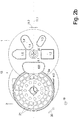
- Figure 4 shows - again viewed in the longitudinal direction 10, usually the longitudinal pressing direction - the arrangement of the holding magnets 7 with two guide tube openings 1.1, 1.2 running parallel next to one another, which additionally in a 1st transverse direction to the longitudinal direction 10 by means of a transverse pressing of the loaf inserted therein of a cross press ram. Since in this case the penetration direction 2 often coincides with the transverse compression direction, the length of the penetration path 2 ', which the knife edge 3a has to cover through the cross section of the guide tube opening, also changes with the extent of the transverse compression.
- two elongated blind holes 24 extending in the penetration direction 2 are provided on both sides of each of the two guide tube openings, with a single such elongated blind hole 24 between them being sufficient if the distance between the two guide tube openings 1.1, 1.2 is sufficiently small.
- the holding magnets 7 can be inserted into these blind holes 24 along these blind holes 24 - preferably by means of magnet holders 25 to be explained - at different longitudinal positions, namely always in the penetration direction 2 in the last or the last two insertion positions along the penetration path 2 ' whose exit side 2a.
- Figures 1a and 3 show the positioning and fastening of the holding magnets 7 in the axial direction 10:
- Figure 1a shows in the right edge area a guide tube turret 1, which is formed in one piece in the axial direction 10, in the middle and in the left area, however, a design in which it consists of discs 1A, 1B successive in the axial direction 10, of which only the first both are shown, while in practice the entire length of the guide tube turret 1 is composed of disks of the same thickness.
- the disks 1A, 1B are of course arranged and fixed to one another in such a way that their guide tube openings 1.1, 1.2 are aligned with one another.
- the holding magnet can then be inserted from the rear side of the foremost disk 1A facing the knife 3, so that the front surface 1a is not interrupted by a holding magnet 7 - even if it is inserted and fixed flush - as is the case with a one-piece guide tube turret 1 is necessary, as in Figure 1a shown at the lower right end of the guide tube turret 1.
- Figure 3 is located in the cutting-side 1st disc 1A next to the shape of the tube openings 1.1 blind holes 24, which are open to the rear side of this disc 1A facing away from the front side 1a.
- this blind hole 24 can have an axial section with an internal thread 23, into which a magnet holder 25 with a corresponding external thread 23 can be screwed, which holds the holding magnet 7 on the bottom of the blind hole 24 with its front face.
- the magnet holder 25 can be sealed with respect to the inner circumference of the blind hole 24 by means of the grooves machined into its outer circumference and the O-ring 16 inserted there or in some other way.
Landscapes
- Life Sciences & Earth Sciences (AREA)
- Forests & Forestry (AREA)
- Engineering & Computer Science (AREA)
- Mechanical Engineering (AREA)
- Shearing Machines (AREA)
- Knives (AREA)
- Details Of Cutting Devices (AREA)
- Media Introduction/Drainage Providing Device (AREA)
- Confectionery (AREA)
Description
Die Erfindung betrifft Schneidemaschinen, bei denen von einem strangförmigen oder laibförmigen Schneidgut Scheiben abgeschnitten werden sollen.The invention relates to cutting machines in which slices are to be cut from a strand-shaped or loaf-shaped material to be cut.
Das Schneidgut ist dabei häufig in einem Führungsrohr geführt, wobei der aus dem Führungsrohr stirnseitig auf der Schneidseite vorstehende Anteil des Schneidgutes durch ein z.B. rotierendes Messer unmittelbar an der schneidseitigen Stirnfläche des Führungsrohres als Scheibe abgetrennt wird.The material to be cut is often guided in a guide tube, with the portion of the material to be cut protruding from the front of the guide tube on the cutting side being cut off as a disc by a rotating knife, for example, directly on the cutting-side end face of the guide tube.
An dieser Stelle soll klargestellt werden, dass dieses Führungsrohr auch nur aus einer axial sehr kurzen sogenannten Schneidbrille bestehen kann, die dasjenige Ende des Schneidgutes teilweise oder vollständig umgibt, von dem die Scheiben abgetrennt werden sollen, und an dessen Stirnfläche sich das Messer entlang bewegt. Im Folgenden wird dennoch durchgängig nur von einem Führungsrohr gesprochen.At this point it should be made clear that this guide tube can only consist of an axially very short so-called cutting goggle, which partially or completely surrounds that end of the material to be cut from which the slices are to be separated and the knife moves along its end face. In the following, however, only one guide tube is used throughout.
Es soll ferner klargestellt werden, dass die vorliegende Anmeldung auch Lösungen umfasst, bei der ein einziges Messer von zwei oder mehr in nebeneinanderliegenden Führungsrohren geführten Laiben gleichzeitig je eine Scheibe abtrennt, und/oder auch Lösungen, bei denen das Führungsrohr Bestandteil eines um seine zentrale Achse drehbaren Führungsrohr-Revolvers ist, um die herum mehrere Führungsrohre angeordnet sind.It should also be made clear that the present application also includes solutions in which a single knife of two or more loaves guided in adjacent guide tubes simultaneously separates one slice, and / or solutions in which the guide tube is part of one around its central axis rotatable guide tube turret, around which a plurality of guide tubes are arranged.
Dabei soll das Messer das Schneidgut an immer dem gleichen, exakt festgelegten axialen Abstand, insbesondere dem Abstand Null, zur Stirnseite des Führungsrohres durchtrennen, denn nur so können Scheiben mit einer definierten Dicke und damit auch mit einem definierten Gewicht erzeugen werden.The knife should always cut through the material to be cut at the same, precisely defined axial distance, in particular the distance zero, to the end face of the guide tube, because this is the only way to produce slices with a defined thickness and thus also with a defined weight.
Das z.B. rotierende Messer wird dabei auf der Seite des Führungsrohres vom Führungsrohr selbst abgestützt, auf der Gegenseite ist eine Abstützung, die ja axialen Bauraum erfordert - sei es durch entsprechend große Dicke des Messers selbst oder eine zusätzliche dortige Abstützvorrichtung - notwendig, aber nachteilig, weil dadurch das Eindringen des Messers in das Schneidgut erschwert wird.The rotating knife, for example, is supported on the side of the guide tube by the guide tube itself, on the opposite side a support that requires axial installation space - be it due to the correspondingly large thickness of the knife itself or an additional support device there - is necessary, but disadvantageous because this makes it more difficult for the knife to penetrate the material to be cut.
Theoretisch wäre ein optimal dünnes Messer die beste Lösung, da es am leichtesten in das Schneidgut eindringt, jedoch weist ein solches Messer häufig nicht die ausreichende Formstabilität und vor allem nicht die ausreichende Lagestabilität, nämlich dicht anliegend an der Stirnfläche des Führungsrohres, auf.Theoretically, an optimally thin knife would be the best solution, as it penetrates the material to be cut the easiest, but such a knife often does not have sufficient dimensional stability and, above all, insufficient positional stability, namely close to the end face of the guide tube.
Dieses Problem ist bei einem Schneidgut mit gleichmäßiger Konsistenz und geringem Schneidwiderstand wie etwa Wurst oder Käse - welches in der Regel auch einen in axialer Richtung durchgängig gleichen Querschnitt besitzt und somit strangförmig ist - noch nicht so akut wie bei einem unregelmäßig strukturierten und geformten Laib eines Schneidgutes wie etwa einem Stück Frischfleisch, welcher dann zusätzlich im Führungsrohr als Formrohr noch in Längsrichtung und/oder Querrichtung vor dem Aufschneiden vorverpresst werden kann.This problem is not yet as acute in the case of items to be sliced with a uniform consistency and low cutting resistance such as sausage or cheese - which generally also has the same cross-section in the axial direction and is therefore strand-shaped - as it is with an irregularly structured and shaped loaf of items to be sliced such as a piece of fresh meat, which can then also be pre-pressed in the guide tube as a shaped tube in the longitudinal direction and / or transverse direction before slicing.
Dabei wird der ungleichmäßige Querschnitt des Fleischlaibes auf den gleichmäßigen Querschnitt des Führungsrohres ausgedehnt, so dass das Schneidgut einen gleichmäßigen Querschnitt in Form eines Stranges oder Kalibers aufweist, was aber auch bewirkt, dass das Schneidgut unter einem erhöhten Druck steht und das außerhalb des Führungsrohres ein Längsanschlag für das aus dem Führungsrohr heraus geschobenes Ende des Schneidgutes vorhanden sein sollte.The uneven cross-section of the meat loaf is expanded to the uniform cross-section of the guide tube, so that the material to be cut has a uniform cross-section in the form of a strand or caliber, but this also causes the material to be cut under a There is increased pressure and that outside the guide tube there should be a longitudinal stop for the end of the material to be sliced that is pushed out of the guide tube.
Da das Messer nicht beidseitig in einem Schneidspalt geführt wird, sondern nur einseitig an der Stirnfläche des Führungsrohres entlang gleitet, ist ohne Zusatzmaßnahme die Gefahr groß, dass das Messer durch Verformung, den unregelmäßigen Widerstand des Schneidgutes oder andere Effekte nicht eng, insbesondere kontaktierend, an der Stirnfläche des Führungsrohres entlang gleitet, sondern in einem geringen Abstand hierzu, was die Dicke und damit das Gewicht der erzeugten Scheibe unerwünschtermaßen verändert.Since the knife is not guided in a cutting gap on both sides, but only slides on one side along the end face of the guide tube, without additional measures there is a great risk that the knife will not be tight, in particular contacting, due to deformation, the irregular resistance of the material to be cut or other effects the end face of the guide tube slides along, but at a small distance therefrom, which undesirably changes the thickness and thus the weight of the disc produced.
Vor allem aber bewirkt dies kein gutes Schneidergebnis an der Scheibe, welches nur erzielt wird, wenn die Schneidkante des Messers ohne Abstand und gegen eine Gegenschneide, in diesem Fall in Form des Innenumfanges der Führungsrohröffnung des Führungsrohres an der Austrittsseite des Führungsrohres entlang gleitet.Above all, however, this does not cause a good cutting result on the disc, which is only achieved if the cutting edge of the knife slides without clearance and against a counter blade, in this case in the form of the inner circumference of the guide tube opening of the guide tube on the outlet side of the guide tube.
Ist dies nicht der Fall, ist der Rand der Scheibe meistens ausgefranst, was aus optischen Gründen nicht erwünscht ist.If this is not the case, the edge of the pane is usually frayed, which is undesirable for optical reasons.
Ein gewachsenes Fleischstück ist von einer sogenannten Silberhaut, einem sehnenartigen, schwer zu durchtrennenden Material, umgeben. Ein sauberes Durchtrennen anstelle eines Durchreissens dieser Silberhaut ist nur möglich, wenn die Schneide des Messers dabei an der Stirnfläche des Führungsrevolvers bzw. Formrevolvers anliegt, vor allem beim Austritt des Messers aus dem Schneidgut, also dem Führungsrohr-Querschnitt.A grown piece of meat is surrounded by a so-called silver skin, a tendon-like material that is difficult to cut. A clean cutting instead of tearing through this silver skin is only possible if the cutting edge of the knife rests against the end face of the guide turret or form turret, especially when the knife emerges from the material to be cut, i.e. the guide tube cross-section.
Aus der
Es hat sich jedoch gezeigt, dass dies zu einer verstärkten Reibung zwischen Messer und Führungsrohr führt, und damit einerseits zu einer Erwärmung dieser Bauteile und auch des darin aufgenommenen Schneidgutes sowie andererseits zu einem erhöhten Kraftaufwand zum Bewegen des Messers.It has been shown, however, that this leads to increased friction between the knife and the guide tube, and thus, on the one hand, to a heating of these components and also of the material to be sliced and, on the other hand, to an increased effort to move the knife.
Auch aus der
Es ist daher die Aufgabe gemäß der Erfindung, eine Vorrichtung und ein Verfahren zum Heranziehen des Messers an die schneidseitige Stirnfläche des Führungsrohres einer Schneidemaschine zur Verfügung zu stellen und dennoch die beschriebenen Nachteile zu vermeiden.It is therefore the object of the invention to provide a device and a method for pulling the knife to the cutting-side end face of the guide tube of a cutting machine and still avoid the disadvantages described.
Diese Aufgabe wird durch die Merkmale der Ansprüche 1 und 14 gelöst. Vorteilhafte Ausführungsformen ergeben sich aus den Unteransprüchen.This object is achieved by the features of
Bei einer gattungsgemäßen Schneidemaschine, bei der das Messer mittels Haltemagneten an der Stirnfläche des Führungsrohres gehalten wird, ist es unerheblich, ob es sich bei dem Messer um ein balkenförmiges Messer, ein rotierende kreisscheibenförmiges oder ein rotierendes sichelförmiges Messer oder um das Messer einer Bandsäge handelt.In a cutting machine of the generic type , in which the knife is held on the end face of the guide tube by means of holding magnets, it is irrelevant whether the knife is a bar-shaped knife, a rotating circular disk-shaped knife or a rotating sickle-shaped knife or the knife of a band saw.
Bei einer erfindungsgemäßen Schneidemaschine sind der oder die Haltemagnete in Eindringrichtung nur nahe der Austrittsseite des Führungsrohr-Querschnittes und außerhalb des Führungsrohr-Querschnittes angeordnet, und nicht nahe der Eintrittsseite.In the case of a cutting machine according to the invention , the holding magnet (s) are arranged in the penetration direction only near the exit side of the guide tube cross section and outside the guide tube cross section, and not near the entry side.
Unter Eindringrichtung wird die Lotrechte auf die Messerkante verstanden, die in der durch die Messerkante und/oder die Hauptebene des Messers definierte Messerebene liegt. Ist die Messerkante gekrümmt, setzt die lotrechte an der Mitte der Länge der Messerkante an.The direction of penetration is understood to mean the perpendicular to the knife edge which lies in the knife plane defined by the knife edge and / or the main plane of the knife. If the knife edge is curved, the perpendicular starts at the middle of the length of the knife edge.
Dadurch wird das Messer erst im letzten Teil der Durchlaufstecke seiner Messerkante durch das Schneidgut, also durch den Führungsrohr-Querschnitt, in Richtung der Stirnfläche des Führungsrohres mit Magnetkraft beaufschlagt und dadurch in der Regel auch in Kontakt mit der Stirnfläche gebracht.As a result, the knife is only subjected to magnetic force in the last part of the passage section of its knife edge through the material to be cut, i.e. through the guide tube cross-section, in the direction of the end face of the guide tube and thereby usually also brought into contact with the end face.
Dies bewirkt zum Einen, dass die Schneidkante des Messers gegenüber der Frontkante des Innenumfanges des Führungsrohr-Querschnittes als Gegenschneide abschert, was einen exakten Schnitt bewirkt, sodass auch die Silberhaut ohne Probleme sauber durchschnitten wird.On the one hand, this has the effect that the cutting edge of the knife shears off as a counter-blade opposite the front edge of the inner circumference of the guide tube cross-section, which causes an exact cut so that the silver skin is also cut cleanly without any problems.
Darüber hinaus bietet dies den Vorteil, dass vor dem Einwirken der Magnetkraft auf das Messer, also im ersten Teil des Durchlaufes der Schneidkante entlang der Eindringstrecke, noch keine Beaufschlagung des Messers mit Magnetkraft in Richtung Stirnfläche des Führungsrohres erfolgt und das Messer die Stirnfläche nicht oder nur mit einer sehr geringen Anlagekraft kontaktiert, so dass dabei kaum eine Erwärmung von Messer und Führungsrohr sowie kaum eine Erhöhung der aufzubringenden Schneidkraft eintritt.In addition, this offers the advantage that before the magnetic force acts on the knife, i.e. in the first part of the passage of the cutting edge along the penetration path, there is no application of magnetic force to the knife in the direction of the end face of the guide tube and the knife does not or only the end face contacted with a very low contact force, so that there is hardly any heating of the knife and guide tube and hardly any increase in the cutting force to be applied.
Insbesondere sind der oder die Haltemagnete nur im letzten Drittel der Eindringstrecke der Messerkante in Eindringrichtung angeordnet.In particular, the holding magnet or magnets are only arranged in the last third of the penetration path of the knife edge in the penetration direction.
Dabei ist der mindestens eine Haltemagnet so nahe wie möglich am äußeren Umfang des Führungsrohr-Querschnittes angeordnet, um das Messer gerade im Bereich des Führungsrohr-Querschnittes mit Magnetkraft in Richtung der Stirnfläche zu beaufschlagen.The at least one holding magnet is arranged as close as possible to the outer circumference of the guide tube cross-section in order to apply magnetic force to the knife in the area of the guide tube cross-section in the direction of the end face.
Vorzugsweise ist der Haltemagnet quer zur Eindringrichtung, also in radialer Richtung des Führungsrohr-Querschnittes, näher als 30 mm, besser näher als 20 mm, besser näher als 10 mm am Umfang des Führungsrohr-Querschnittes angeordnet.The holding magnet is preferably arranged transversely to the penetration direction, i.e. in the radial direction of the guide tube cross section, closer than 30 mm, better closer than 20 mm, better closer than 10 mm to the circumference of the guide tube cross section.
In axialer Richtung sind der eine oder die mehreren Haltemagnete so nahe an der Längsposition der vorderen, schneidseitigen Stirnfläche angeordnet, dass die Zugkraft des Haltemagneten an der Längsposition der schneidseitigen Stirnfläche auf das Messer noch eine vorgegebene Mindest-Zugkraft erreicht oder übersteigt.In the axial direction, the one or more holding magnets are arranged so close to the longitudinal position of the front, cutting-side face that the tensile force of the holding magnet on the knife at the longitudinal position of the cutting-side face still reaches or exceeds a predetermined minimum tensile force.
Vorzugsweise ist die Längsposition des Haltemagneten hierfür einstellbar.The longitudinal position of the holding magnet is preferably adjustable for this purpose.
Die Mindest-Zugkraft des einzelnen, in der Maschine montierten, Magneten an der Längsposition der schneidseitigen Stirnfläche sollte mindestens zwischen 100 N und 10 N, besser zwischen 70 N und 20 N, besser zwischen 50 N und 30 N betragen, insbesondere gegenüber dem verwendeten Messer-Werkstoff.The minimum tensile force of the individual magnets mounted in the machine at the longitudinal position of the cutting-side face should be at least between 100 N and 10 N, better between 70 N and 20 N, better between 50 N and 30 N, especially in relation to the knife used -Material.
Die Summe der Mindest-Zugkräfte aller an einem Führungsrohr vorhandenen Haltemagnete sollte zwischen 400 N und 40 N, besser zwischen 280 N und 160 N, besser zwischen 200 N und 120 N, betragen, insbesondere gegenüber dem verwendeten Messer-Werkstoff. Alle an einem Führungsrohr vorhandenen Haltemagnete sollen insbesondere diejenigen Haltemagnete sein, die beim Abtrennen einer Scheibe, die aus diesem Führungstor vorsteht, maximal alle gemeinsam auf das abtrennende Messer einwirken.The sum of the minimum tensile forces of all holding magnets present on a guide tube should be between 400 N and 40 N, better between 280 N and 160 N, better between 200 N and 120 N, especially compared to the knife material used. All holding magnets present on a guide tube should in particular be those holding magnets which, when a pane protruding from this guide gate is cut off, at most all of them act together on the cutting knife.
Erst dann ist eine sichere Kontaktierung der Messerkante gegenüber der Stirnfläche ab dem Beaufschlagen des Messers mittels Magnetkraft sichergestellt.Only then is reliable contacting of the knife edge with respect to the end face ensured from the application of the knife by means of magnetic force.
Als Werkstoff für das Messer wird vorzugsweise so genannter Messerstahl verwendet, der in der Regel so definiert ist, dass dessen Sortennummer mit 1.40 - 1.46 beginnt, vorzugsweise mit 1.40.So-called knife steel is preferably used as the material for the knife, which is usually defined in such a way that its grade number starts with 1.40 - 1.46, preferably 1.40.
Insbesondere sollte der Nickelgehalt maximal 2,5 Gewichts-% betragen und der Kohlenstoffgehalt maximal 1,2 Gewichts-%, während der Chromgehalt mindestens 10,5 Gewicht-%, besser 13 - 15 Gewichts-%, betragen sollte. Falls Molybdän enthalten ist, sollte dessen Anteil nicht höher als 1,0 Gewichts-% betragen.In particular, the nickel content should be a maximum of 2.5% by weight and the carbon content a maximum of 1.2% by weight, while the chromium content should be at least 10.5% by weight, better still 13-15% by weight. If molybdenum is contained, its proportion should not be higher than 1.0% by weight.
Dadurch sind solche Messerstähle nichtrostend und noch härtbar, wobei meist Härten von 50 - 60 HRC angestrebt werden.As a result, such knife steels are rustproof and can still be hardened, with hardnesses of 50 - 60 HRC usually being aimed for.
Die in der Sortennummer danach folgende Zähler-Nummer bewegt sich vorzugsweise zwischen 16 und 34 und beträgt vorzugsweise 21.The counter number following in the type number is preferably between 16 and 34 and is preferably 21.
Die danach folgenden letzten beiden Ziffern der Sortennummer für das Stahlgewinnungsverfahren und den Behandlungszustand betragen vorzugsweise 3 für das Stahlgewinnungsverfahren und/oder 4 für den Behandlungszustand.The subsequent last two digits of the type number for the steel production process and the treatment state are preferably 3 for the steel production process and / or 4 for the treatment state.
Vorzugsweise wird somit als Messerstahl ein Stahl der Sortennummer 1.4021.34 verwendet.A steel of the grade number 1.4021.34 is therefore preferably used as the knife steel.
Der für das Messer verwendete Stahl muss natürlich mittels Magnetkraft beaufschlagbar sein, also ein weichmagnetischer Werkstoff sein.The steel used for the knife must of course be able to be acted upon by magnetic force, i.e. it must be a soft magnetic material.
Vorzugsweise ist das Messer gegenüber der Stirnfläche des Führungsrohres in axialer Richtung so positioniert, dass die dem Führungsrohr zugewandte Seite des Messers ohne Beaufschlagung mit Magnetkraft einen schmalen Schneidspalt von höchstens 0,5 mm, besser höchstens 0,3 mm, besser höchstens 0,2 mm zum Führungsrohr einnimmt.The knife is preferably positioned with respect to the end face of the guide tube in the axial direction in such a way that the one facing the guide tube On the side of the knife without application of magnetic force, a narrow cutting gap of no more than 0.5 mm, better no more than 0.3 mm, better no more than 0.2 mm to the guide tube.
Um das Messer mittels der Magnetkraft des mindestens einen Haltemagneten bis zur Kontaktierung an die Stirnfläche heranzuziehen - falls das Messer die Stirnfläche ohne Beaufschlagung durch Magnetkraft nicht kontaktiert - sollte das Messer eine Dicke von höchstens 10 mm, insbesondere höchstens 8 mm, insbesondere höchstens 6 mm, insbesondere höchstens 4 mm, insbesondere höchstens 3 mm besitzen.In order to pull the knife by means of the magnetic force of the at least one holding magnet until it makes contact with the end face - if the knife does not contact the end face without being applied by magnetic force - the knife should have a thickness of at most 10 mm, in particular at most 8 mm, in particular at most 6 mm, in particular have a maximum of 4 mm, in particular a maximum of 3 mm.
Aus dem gleichen Grund sollte das Messer in Eindringrichtung eine Erstreckung von mindestens 10 mm, insbesondere mindestens 30 mm, insbesondere mindestens 50 mm besitzen. Bei einem kreisscheibenförmigen, rotierenden Messer ist die Erstreckung von der Schneidkante bis zum Lagerbock, in dem das Messer gelagert ist, zu messen.For the same reason, the knife should have an extension of at least 10 mm, in particular at least 30 mm, in particular at least 50 mm, in the penetration direction. In the case of a circular disk-shaped rotating knife, the extent from the cutting edge to the bearing block in which the knife is mounted is to be measured.
Das Messer besteht ohnehin in aller Regel aus einem weichmagnetischen Material, also einem Material, auf welches mittels eines Magneten eine Kraft ausgeübt werden kann. Vorzugsweise besteht das Messer aus hygienischen Gründen aus Edelstahl, also einem unter den Einsatzbedingungen einer solchen Schneidemaschine nicht rostenden, meist hoch legiertem Stahl, der aber gleichzeitig weichmagnetische Eigenschaften besitzt.As a rule, the knife consists of a soft magnetic material, that is, a material on which a force can be exerted by means of a magnet. For reasons of hygiene, the knife is preferably made of stainless steel, that is to say a mostly high-alloy steel which does not rust under the conditions of use of such a cutting machine, but which at the same time has soft magnetic properties.
Vorzugsweise handelt es sich bei dem Messer um ein nur einseitig angeschliffenes Messer, wobei sich die Anschliff-Seite vorzugsweise auf der vom Führungsrohr abgewandten Seite des Messers befindet. Daher müssen unabhängig von den exakten Abmessungen des Messers, also seinem Nachschleif-Zustand, keine Änderungen an der Positionierung der Magnete, insbesondere in axialer Richtung, vorgenommen werden.The knife is preferably a knife that is only sharpened on one side, the sharpened side preferably being on the side of the knife facing away from the guide tube. Therefore, regardless of the exact dimensions of the knife, that is, its regrinding state, no changes to the positioning of the magnets, in particular in the axial direction, have to be made.
Ausführungsformen gemäß der Erfindung sind im Folgenden beispielhaft näher beschrieben. Es zeigen:
Figuren 1a -d:- eine Schneidemaschine im Längsschnitt in unterschiedlichen Arbeitsstellungen,
Figuren 2a - c:- einen Querschnitt durch die Schneidemaschine entlang der Linie II-II in unterschiedlichen Arbeitsstellungen,
- Figur 3:
- eine
Vergrößerung aus Figur 1a , - Figur 4:
- eine Aufsicht auf ein doppeltes Führungsrohr.
- Figures 1a -d:
- a cutting machine in longitudinal cut in different working positions,
- Figures 2a - c:
- a cross section through the cutting machine along the line II-II in different working positions,
- Figure 3:
- an enlargement
Figure 1a , - Figure 4:
- a plan view of a double guide tube.
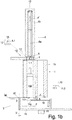
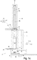
Der grundsätzliche, gattungsgemäße Aufbau der Schneidemaschine lässt sich am besten in der Zusammenschau der
Ein - in diesem Fall aufrecht stehender und vom Querschnitt her runder, insgesamt zylindrischer - Führungsrohr-Revolver 1 ist um eine Drehachse 1', die in diesem Fall ebenfalls aufrecht steht und die Symmetrieachse des zylindrischen Führungsrohr-Revolvers 1 darstellt - drehbar im - nicht dargestellten - Grundgestell der Schneidemaschine gelagert.The basic, generic structure of the cutting machine can best be seen in the synopsis of the
A guide tube turret 1 - in this case upright and round in cross-section, cylindrical overall - is rotatable about an axis of rotation 1 ', which in this case is also upright and represents the axis of symmetry of the cylindrical guide tube turret 1 - not shown - The base frame of the cutting machine is stored.
Über den Umfang verteilt befinden sich in dem Führungsrohr-Revolver 1 mehrere axial verlaufende Führungsrohr-Öffnungen 1.1 - 1.5 mit unterschiedlichem freiem innerem Querschnitt 1.1' - 1.5', die sowohl am vorderen, unteren Schneidende 1a als auch am oberen, hinteren Beladeende 1b münden, also stirnseitig jeweils offen sind.Distributed over the circumference in the
Die Führungsrohr-Öffnungen 1.1 - 1.5 dienen zum Aufnehmen eines in Scheiben aufzuschneidenden Laibes 100, der im Ausgangszustand eine längliche, aber unregelmäßige Form besitzt, sodass entsprechend des Querschnittes des Laibes 100 im Ausgangszustand dieser wahlweise in eine vom Querschnitt her am besten passende Führungsrohr-Öffnung 1.1 - 1.5 von oben, vom Beladeende 1b her, eingeführt werden kann, die sich hierfür natürlich nicht an der Schneidposition 12 befinden darf, da dort der Längspress-Antrieb 6 das Einführen von oben verhindert.The guide tube openings 1.1-1.5 are used to receive a
Als Schneidposition 12 wird diejenige Winkellage oder Winkelsegment bezüglich der Drehachse 1' des Führungsrohr-Revolvers 1 bezeichnet, die von dem im Einsatz befindlichen Messer überstrichen wird. Bei einem radial bezüglich des Führungsrohr-Revolvers 1 bewegten Messer ist die Schneidposition 12 die Winkellage, an der sich die Eindringrichtung 2 befindet.That angular position or angular segment with respect to the axis of rotation 1 'of the
Unmittelbar vor, also unterhalb, der unteren Stirnfläche 1a, dem Schneidende 1a des Führungsrohres 1, ist ein rotierendes, kreisscheiben-förmiges Messer 3 angeordnet, welches um eine Messerachse 3' rotierend angetrieben wird, die vorzugsweise parallel zur Schaltachse 1', der Drehachse des Führungsrohr-Revolvers 1, liegt.Immediately in front of, i.e. below, the
Das rotierende Messer 3 kann in einer 1. Querrichtung 11.1 zur Längsrichtung 10, die der Richtung der Schaltachse 1' des Führungsrohr-Revolvers 1 entspricht, radial zur in der Schneidposition 12 befindlichen Führungsrohr-Öffnung z.B. 1.1 hin und her verfahren werden zum Abtrennen von Scheiben 101 vom Schneidgut 100.The
Die abgetrennte Scheibe 101 fällt auf den darunter angeordneten Abförderer 8 und wird von diesem z.B. in Blickrichtung der
Die
- In
Figur 2a sowie Figur 1a befindet sichdas Messer 3 noch vollständig außerhalb des Umfanges des Führungsrohr-Revolvers 1. - In
Figur 2b sindMesser 3 und die - hier nicht sichtbare -Anschlagplatte 14 gemeinsam bereits so weit nach rechts inder 1. Querrichtung 11.1 verfahren, dassdas Messer 3 inden Laib 100 bereits eingedrungen ist und der bereits abgetrennte Teil derScheibe 101 über dieFunktionskante 14a der Anschlagplatte 14 hinaus zwischenMesser 3 und Anschlagplatte 14 vorsteht. - In
Figur 2c undFigur 1c ist dieScheibe 101 vollständig abgetrennt,das Messer 3 deckt also den Querschnitt der an der Schneidposition befindlichen Führungsrohr-Öffnung vollständig ab und dieAnschlagplatte 14 befindet sich in dieser Blickrichtung vollständig außerhalb des Querschnittes 1.1' dieser Führungsrohr-Öffnung 1.1.
- In
Figure 2a asFigure 1a theknife 3 is still completely outside the circumference of theguide tube turret 1. - In
Figure 2b Knife 3 and the stop plate 14 - not visible here - have already moved so far to the right in the 1st transverse direction 11.1 that theknife 3 has already penetrated theloaf 100 and the already separated part of thedisc 101 over thefunctional edge 14a of theStop plate 14 also protrudes betweenknife 3 and stopplate 14. - In
Figure 2c andFigure 1c thedisc 101 is completely separated, theknife 3 thus completely covers the cross section of the guide tube opening located at the cutting position and thestop plate 14 is located completely outside the cross section 1.1 'of this guide tube opening 1.1 in this viewing direction.
Statt einer linearen, oszillierenden Bewegung in Querrichtung 11.1 kann die Messerachse 3' auch eine bogenförmige, oszillierende, oder kreisförmig umlaufende Bewegung vollziehen, um jeweils eine Scheibe 101 abzutrennen.Instead of a linear, oscillating movement in the transverse direction 11.1, the
Zum Herstellen eines gleichmäßigen Querschnittes des Laibes 100 vor dem Aufschneiden in Scheiben wird dieser in Längsrichtung 10 in der Führungsrohr-Öffnung 1.1, in der er sich befindet, verpresst.To produce a uniform cross section of the
Für das Längsverpressen ist oberhalb des Führungsrohr-Revolvers 1 an der sogenannten Schneidposition 12 ein Längspress-Antrieb 6, betrachtet in Richtung der Schaltachse 1' innerhalb des Umfanges des Führungsrohr-Revolvers 1 liegend, am Grundgestell der Maschine angeordnet.For the longitudinal pressing, a longitudinal
Der Längspress-Antrieb 6 besteht aus einem Arbeitszylinder, vorzugsweise einem Hydraulikzylinder, dessen in Längsrichtung 10 verfahrbare Kolbenstange 6a bei Beaufschlagung mit Arbeitsmedium aus dem unteren, offenen Ende des Zylinders 6b zunehmend ausfährt und mit ihrem vorderen Ende einen Längs-Pressstempel 4.1, der in den Querschnitt 1.1' der darunter befindlichen Führungsrohr-Öffnung 1.1 hineinpasst, in diese einschiebt bis zur Anlage am Laib 100 und diesen in Längsrichtung 10 nach unten presst gegen einen Anschlag.The
Als Anschlag dient in diesem Fall die gemäß
In einem scheibenförmigen Pressstempel-Revolver 13 sind kreisförmig verteilt um dessen Drehachse 13' Längs-Pressstempel 4.1 - 4.5 angeordnet, deren Querschnitte jeweils einem der Querschnitte 1.1' - 1.5' der Führungsrohr-Öffnungen 1.1 - 1.5 entsprechen und so im Pressstempel-Revolver 13 angeordnet sind, dass sie genau und vorzugsweise flüssigkeitsdicht in jeweils eine der Führungsrohr-Öffnungen 1.1 - 1.5 passen, wenn sie sich in der Schneidposition 12 über dieser dazu passenden Führungsrohr-Öffnung befinden.In a disc-shaped
Der Pressstempel-Revolver 13 ist um die ebenfalls aufrechte, parallel zur Schaltachse 1' verlaufende, zu dieser jedoch in einer Querrichtung versetzte, Schaltachse 13' drehbar, sodass bei einer bestimmten, an der Schneidposition befindlichen Führungsrohr-Öffnung 1.1 der den gleichen Querschnitt 4.1' aufweisende Längs-Pressstempel 4.1 durch entsprechendes Drehen des Pressstempel-Revolvers 13 über dieser Führungsrohr-Öffnung 1.1 positioniert werden kann.The
Beim Annähern des unteren, freien Endes der Kolbenstange 6a gegen die Oberseite des in der Schneidposition 12 befindlichen, noch im Pressstempel-Revolver 13 gehaltenen, Längs-Pressstempels 4.1 werden diese automatisch miteinander verbunden mittels einer Kupplung 9, indem am unteren freien Ende der Kolbenstange 6a einerseits und/oder der Oberseite jedes der Längs-Pressstempel 4.1 - 4.5 andererseits entsprechende, zusammenwirkende Kupplungs-Teile 9a, b vorhanden sind.When the lower, free end of the
Die auf der Oberseite der Längs-Pressstempel 4.1 - 4.5 befindlichen Kupplungsteile 9a liegen auf einer Kreisbahn um die Schaltachse 13' des Pressstempel-Revolvers 13. Wenn sich der entsprechende Längs-Pressstempel 4.1 fluchtend und über der Schneidposition 12 befindet, genau im Bewegungsweg des am vorderen Ende der Kolbenstange 6a angeordneten anderen, komplementären Kupplung-Teiles 9b.The
Beim Zurückziehen der Kolbenstange 6a mit dem daran befindlichen Längs-Pressstempels 4.1 fährt der Längs-Pressstempel 4.1 beim Erreichen der entsprechenden Aussparung im Pressstempel-Revolver 13 gegen einen Stempelanschlag 15 an oder in dieser Aussparung, sodass bei weiterem Zurückziehen der Kolbenstange 6a sich die Kupplung 9 löst und den entsprechenden Längs-Pressstempel 4.1 automatisch freigibt, der nun wieder in dem Pressstempel-Revolver 13 in der für den Längs-Pressstempel 4.1 vorgesehenen Aussparung gehalten wird, sei es z.B. magnetisch oder durch dortige geeignete Rastelemente.When the
Indem der Längspress-Antrieb 6 nur über der Schneidposition 12 vorhanden ist, vereinfacht sich der Aufbau der Schneidemaschine.Since the
Schaltachse 1' bedeutet, dass der Führungsrohr-Revolver 1, gedreht werden kann, aber zusätzlich in bestimmten Winkelstellungen arretiert werden kann, sodass also von einer zur nächsten der definierten Winkelstellungen weitergeschaltet werden kann.Switching axis 1 'means that the
Im Folgenden wird anstelle von Verlagerungsrichtung 2 der Messerachse 3' immer von der 1. Querrichtung 11.1 gesprochen, ohne die Erfindung hierauf zu beschränken, obwohl die Verlagerungsrichtung 2 auch eine andere quer zur Längsrichtung 10 des Führungsrohr-Revolvers 1 verlaufende Richtung sein kann.In the following, instead of the direction of
Das Messer 3 ist drehbar um seine Messerachse 3' an einem Schlitten 19 gelagert, der in dieser Verlagerungsrichtung 2 gegenüber dem Schneid-Grundgestell 18 verfahrbar ist. Auch die Anschlagplatte 14 wird von dem Schlitten 19 getragen, ist diesem gegenüber jedoch zumindest in axialer Richtung 10 verstellbar, gegebenenfalls auch in radialer Richtung.The
Beim Schneidvorgang bewegen sich Messer 3 und Anschlagplatte 14 vorzugsweise synchron in der Eindringrichtung 2, vorzugsweise 1. Querrichtung 11.1, sodass die entstehende Scheibe 101 zunehmend durch den Spalt zwischen der Schneide 3a des Messers 3 und der dem Messer zugewandten Funktionskante 14a der Anschlagplatte 14 hindurchgeschoben wird.During the cutting process,
Die Funktionskante 14a ist - in axialer Richtung 10, also beispielsweise von unten betrachtet- vorzugsweise konkav gekrümmt und verläuft in dieser Blickrichtung fluchtend oder leicht radial nach außen versetzt, insbesondere in einem über die Länge der Funktionskante gleichbleibenden Abstand, gegenüber dem kreisförmigen Umfang der Schneide 3a.The
Vorzugsweise kann die Anschlagplatte 14 und damit deren Funktionskante 14a zusätzlich gemäß
Diese sowie alle anderen Bewegungen bewegter Teile der Schneidemaschine werden von einer nicht dargestellten Steuerung angesteuert.These and all other movements of moving parts of the cutting machine are controlled by a controller, not shown.
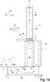
Zum Einen ist die Anschlagplatte 14 soweit hochgefahren, dass sie unmittelbar an der unteren Stirnfläche des Führungsrohr-Revolvers 1, dem Schneidende 1a, anliegt, wie es als Anschlag für das Längs-Verpressen des Laibes 100 an der Schneidposition 12 notwendig sein kann.
On the one hand, the
Des Weiteren ist das Messer 3 so weit von der Schaltachse 1' des Führungsrohr-Revolvers 1 weg verlagert, dass es sich betrachtet in Längsrichtung 10 vollständig außerhalb des Querschnittes des Führungsrohr-Revolvers 1 befindet, sodass das Messer 3, welches auf seiner Unterseite vom Schlitten 19 abgestützt wird, von der Oberseite her über seine gesamte Fläche frei zugänglich ist und nach Lösen eines Schnellverschluss 20 nach oben abgenommen und gegen ein anderes Messer ausgetauscht werden kann.Furthermore, the
Die in den
Erfindungsgemäß sind außerhalb des Führungsrohr-Querschnittes 1.1', 1.2' im Führungsrohr nahe dessen schneidseitiger Stirnfläche 1a Haltemagnete 7 vorhanden, jedoch in Eindringrichtung 2 nur nahe des Endes der Eindringstrecke 2':
Wie
How
Zur Anpassung an diese Veränderung sind beidseits jeder der beiden Führungsrohr-Öffnungen zwei längliche, sich in Eindringrichtung 2 erstreckende Sacklöcher 24 vorhanden, wobei bei ausreichend geringem Abstand zwischen den beiden Führungsrohr-Öffnungen 1.1, 1.2 ein einziges solches längliches Sackloch 24 dazwischen genügt.To adapt to this change, two elongated
Entlang dieser Sacklöcher 24 können die Haltemagnete 7 - vorzugsweise mittels noch zu erläuternder Magnethalter 25 - an unterschiedlichen Längspositionen in diese Sacklöcher 24 eingesetzt werden, nämlich immer in Eindringrichtung 2 in die letzte oder die letzten beiden Einsetz-Positionen entlang der Eindring-Strecke 2' nahe deren Austrittsseite 2a.The holding
Die
Gemäß
Gemäß
Wie in der linken Hälfte der
In der rechten Bildhälfte ist eine demgegenüber wesentlich einfachere Bauform dargestellt, in der der Magnethalter 25 - mit oder ohne Abdichtung - eine solche axiale Länge besitzt, dass er nach Einsetzen des Haltemagneten 7 in das Sackloch 24 und nachfolgendem Einsetzen des Magnethalters 25 mit der Rückseite der Scheibe 1A fluchtet und durch die darauffolgende Scheibe 1B in seiner Axialposition gesichert wird.In the right half of the figure, a much simpler design is shown in contrast, in which the magnet holder 25 - with or without a seal - has such an axial length that after inserting the holding
- 11
- Führungsrohr, Führungsrohr-RevolverGuide tube, guide tube turret
- 1'1'
- Drehachse, SchaltachseRotation axis, switching axis
- 1a1a
- Schneid-Ende, StirnflächeCutting end, face
- 1b1b
- Belade-Ende, StirnflächeLoading end, end face
- 1.1, 1.21.1, 1.2
- Führungsrohr-ÖffnungGuide tube opening
- 1.1', 1.2'1.1 ', 1.2'
- innerer Querschnittinner cross section
- 22
- EindringrichtungDirection of penetration
- 2'2 '
- EindringstreckePenetration distance
- 2a2a
- Austrittsseite, AustrittsendeExit side, exit end
- 33
- Messerknife
- 3'3 '
- MesserachseKnife axis
- 3a3a
- Schneide, SchneidkanteCutting edge, cutting edge
- 4.1-4.54.1-4.5
- Längs-PressstempelLongitudinal ram
- 4'4 '
- Längs-PressrichtungLongitudinal pressing direction
- 5.1-5.55.1-5.5
- Quer-PressstempelCross press ram
- 5'5 '
- Quer-PressrichtungCross pressing direction
- 66th
- Längspress-AntriebLongitudinal press drive
- 6a6a
- KolbenstangePiston rod
- 6b6b
- Zylindercylinder
- 77th
- HaltemagnetHolding magnet
- 88th
- AbfördererConveyor
- 99
- Kupplungcoupling
- 9a, b9a, b
- Kupplungs-TeilCoupling part
- 1010
- axiale Richtung, Längsrichtung, Längspressrichtungaxial direction, longitudinal direction, longitudinal pressing direction
- 1111
- Querrichtung, radiale RichtungTransverse direction, radial direction
- 11.111.1
- erste Querrichtung,first transverse direction,
- 11.211.2
- zweite Querrichtung,second transverse direction,
- 1212th
- SchneidpositionCutting position
- 1313th
- Pressstempel-RevolverPress ram turret
- 13'13 '
- Drehachse, SchaltachseRotation axis, switching axis
- 1414th
- Anschlagelement, AnschlagplatteStop element, stop plate
- 14a14a
- FunktionskanteFunctional edge
- 1515th
- StempelanschlagPunch stop
- 1616
- O-RingO-ring
- 1717th
- ZwischenplatteIntermediate plate
- 1818th
- Schneid-GrundgestellCutting base frame
- 1919th
- SchlittenSledge
- 2020th
- ZentralverschlussCentral locking
- 2121
- Vertiefungdeepening
- 2222nd
- Durchbruchbreakthrough
- 2323
- Innengewinde, AussengewindeInternal thread, external thread
- 2424
- SacklochBlind hole
- 2525th
- MagnethalterMagnet holder
- 100100
- Laib, SchneidgutLoaf, food to be cut
- 101101
- Scheibedisc
- AA.
- Abstanddistance
- DD.
- Dickethickness
Claims (15)
- Cutting machine for cutting a material (2) to be cut into slices (101) with- at least one guide tube (1) running in the longitudinal direction (10) with at least one guide tube opening (1.1, 1.2) open at each end face for receiving the material to be cut (100),- a blade (3) which is positioned in the longitudinal direction (10) directly at the cutting end face (1a) of the guide tube (1),- at least one holding magnet (7) in or at the guide tube (1) positioned in the longitudinal direction (10) near the front, cutting end face (1a) of the guide tube (1), which pulls the blade (3) into contact with the front end face (1a) of the guide tube (1),characterised in that
in the penetration direction (2) of the blade (3) into the guide tube cross-section (1.1', 1.2') the at least one holding magnet (7) is arranged only near the outlet side (2a) of the guide tube cross-section (1.1', 1.2'). - Cutting machine according to claim 1,
characterised in that
the at least one holding magnet (8) is arranged transversely to the penetration direction (2) of the blade (3) close to the circumference of the guide tube cross-section (1.1', 1.2'). - Cutting machine according to one of the preceding claims,
characterised in that
the holding magnet (7) is positioned in the longitudinal direction (10) so close to the front, cutting end face (1a) of the guide tube (1) that the pulling force of the holding magnet (7) at the front end face (1a) reaches a predetermined minimum pulling force. - Cutting machine according to one of the preceding claims,
characterised in that
the longitudinal position of the holding magnet (7) is adjustable. - Cutting machine according to one of the preceding claims,
characterised in that
the blade (3) is not thicker than 10 mm, in particular not thicker than 8 mm, in particular not thicker than 6 mm, in particular not thicker than 4 mm, in particular not thicker than 3 mm. - Cutting machine according to one of the preceding claims,
characterised in that
the blade (3) has an extension in the direction of penetration (2) of at least 10 mm, in particular at least 30 mm, in particular at least 50 mm. - Cutting machine according to one of the preceding claims,
characterised in that- the blade (3) is made of soft magnetic stainless steel, in particular soft magnetic stainless high-alloy steel,and/or- the type number of the material of the blade (3) begins with 1.40 - 1.46, preferably with 1.40 and its subsequent counter number is between 16 and 34, preferably 20 or 21, in particular the variety number is 1.4021.34and/or- wherein the nickel content of the material of the blade (3) is a maximum of 2.5% by weight and the carbon content should be a maximum of 1.2% by weight, while the chromium content should be at least 10.5% by weight, better 13-15% by weight. - Cutting machine according to one of the preceding claims,
characterised in that- the minimum pulling force of the individual holding magnet (7) mounted on the cutting end face (1a), in particular to soft magnetic, stainless blade steel, is between 100 N and 10 N, better between 70 N and 20 N, better between 50 N and 30 N,- the blade (3) is a blade (3) ground on one side only, on the side opposite the guide tube (1). - Cutting machine according to one of the preceding claims,
characterised in that
the sum of the minimum pulling forces of the holding magnets (7) present on a guide tube (1.1, 1.2) on the cutting end face (1a), in particular to soft magnetic, stainless blade steel, is between 400 N and 40 N, better between 280 N and 160 N, better between 200 N and 120 N. - Cutting machine according to one of the preceding claims,
characterised in that- the at least one holding magnet (7) is arranged transversely to the penetration direction (2) of the blade (3) closer than 30 mm, better than 20 mm, better than 10 mm to the circumference of the guide tube cross-section (1.1', 1.2'), closer than 30 mm, better than 20 mm, better than 10 mmand/or- the at least one holding magnet (7) is detachably fastened to or at the guide tube (1). - Cutting machine according to one of the preceding claims, characterised in that- a guide tube turret (1) consists of discs (1A, 1B) following one another in the axial direction (10),- the holding magnet (7) is inserted from the rear side into a blind hole (24) in the frontmost disc (1A) facing the blade (3) the blind hole (24) being open towards the rear side of this disc (1A) so that its front surface (1a) is closed in front of the holding magnet (7).
- Cutting machine according to claim 11,
characterised in that- either this blind hole (24) has an axial section with an internal thread (23) into which a magnet holder (25) with a corresponding external thread (23) can be screwed, which magnet holder holds the holding magnet (7) with its front end face at the bottom of the blind hole (24),- or the magnet holder (25) has such an axial length that, after insertion of the holding magnet (7) into the blind hole (24) and subsequent insertion of the magnetic holder (25), it is aligned with the rear side of the slice (1A). - Cutting machine according to one of the claims 11 or 12,
characterised in that
the magnetic holder (25) is sealed with respect to the inner circumference of the blind hole (24), in particular by means of a groove incorporated in its outer circumference and an O-ring (16) inserted therein. - Method for cutting a material to be cut (100) into slices (101), the material is at least partially accommodated in a guide tube opening (1.1, 1.2) running in the longitudinal direction (10), whereby- the cutting edge (3a) of a blade (3) sweeps over the guide tube cross-section (1.1', 1.2') along the end face (1a), and- where the blade (3) is pulled to the front end face (1a) of the guide tube (1) by the force of a holding magnet (7),characterised in that
the force of the holding magnet (7) is exerted against the blade (3) only near the outlet side (2a) of the penetration section (2') through the guide tube cross-section (1.1', 1.2'). - Method according to claim 14,
characterised in that
the position of the holding magnet (7) transverse to the longitudinal direction (10) is selected and, if necessary, changed as a function of the degree of transverse compression of a material (100) to be cut in the guide tube opening (1.1, 1.2).
Priority Applications (1)
| Application Number | Priority Date | Filing Date | Title |
|---|---|---|---|
| PL19212889T PL3670121T3 (en) | 2018-12-18 | 2019-12-02 | Cutting machine for strand-shaped material |
Applications Claiming Priority (1)
| Application Number | Priority Date | Filing Date | Title |
|---|---|---|---|
| DE102018132654.8A DE102018132654A1 (en) | 2018-12-18 | 2018-12-18 | Cutting machine for strand-like material to be cut |
Publications (2)
| Publication Number | Publication Date |
|---|---|
| EP3670121A1 EP3670121A1 (en) | 2020-06-24 |
| EP3670121B1 true EP3670121B1 (en) | 2021-04-21 |
Family
ID=68762618
Family Applications (1)
| Application Number | Title | Priority Date | Filing Date |
|---|---|---|---|
| EP19212889.0A Active EP3670121B1 (en) | 2018-12-18 | 2019-12-02 | Cutting machine for strand-shaped material |
Country Status (6)
| Country | Link |
|---|---|
| US (1) | US11426892B2 (en) |
| EP (1) | EP3670121B1 (en) |
| CN (1) | CN212218595U (en) |
| DE (1) | DE102018132654A1 (en) |
| ES (1) | ES2875390T3 (en) |
| PL (1) | PL3670121T3 (en) |
Families Citing this family (6)
| Publication number | Priority date | Publication date | Assignee | Title |
|---|---|---|---|---|
| DE102018132899B3 (en) * | 2018-12-19 | 2020-03-26 | Martin Bergmann | Magazine turret device for portioning machine |
| CN111844204A (en) * | 2020-07-24 | 2020-10-30 | 杭州轩霸科技有限公司 | Mainboard cutting positioning adjustment device for computer |
| CN112356171A (en) * | 2020-11-06 | 2021-02-12 | 常德宜居建筑材料有限公司 | Environment-friendly wood cutting device and working principle thereof |
| DE102021103850A1 (en) | 2021-02-18 | 2022-08-18 | Tvi Entwicklung Und Produktion Gmbh | Multi-lane slicing machine with one stop plate per lane and method of operating same |
| CN116511933B (en) * | 2023-07-05 | 2023-09-05 | 云南建源电力器材有限公司 | Transmission line iron tower component cutting and polishing integrated equipment |
| CN117162167B (en) * | 2023-11-03 | 2024-03-22 | 雅安市兴元塑料制品有限公司 | Port rotary cutting equipment for processing fiber reinforced pipe |
Family Cites Families (7)
| Publication number | Priority date | Publication date | Assignee | Title |
|---|---|---|---|---|
| US8337281B2 (en) * | 2009-06-19 | 2012-12-25 | Hantover, Inc. | Self-aligning rotary blade holder for sharpener |
| DE102010002279A1 (en) * | 2010-02-24 | 2011-08-25 | Reifenhäuser, Uwe, 57632 | Machine for cutting a strand-shaped food |
| DE102010035657B4 (en) * | 2010-03-19 | 2015-01-29 | Anton & Völkl Patente Ug (Haftungsbeschränkt) & Co. Kg | portioning |
| DE102010013891A1 (en) * | 2010-04-07 | 2011-10-13 | Weber Maschinenbau Gmbh Breidenbach | Device for slicing food products |
| DE102010035656B4 (en) | 2010-08-27 | 2020-03-05 | Tvi Entwicklung Und Produktion Gmbh | Portioning machine for strand-like cut material |
| ITMI20112198A1 (en) * | 2011-12-01 | 2013-06-02 | Gaetano Scattolin | CIRCULAR BLADE FOR SLICERS, PARTICULARLY FOR INDUSTRIAL-TYPE SLICERS. |
| US9050733B2 (en) * | 2012-05-08 | 2015-06-09 | Premark Feg L.L.C. | Food product slicer with removable knife cover plate and associated method |
-
2018
- 2018-12-18 DE DE102018132654.8A patent/DE102018132654A1/en active Pending
-
2019
- 2019-12-02 PL PL19212889T patent/PL3670121T3/en unknown
- 2019-12-02 ES ES19212889T patent/ES2875390T3/en active Active
- 2019-12-02 EP EP19212889.0A patent/EP3670121B1/en active Active
- 2019-12-17 US US16/717,126 patent/US11426892B2/en active Active
- 2019-12-18 CN CN201922277022.3U patent/CN212218595U/en active Active
Non-Patent Citations (1)
| Title |
|---|
| None * |
Also Published As
| Publication number | Publication date |
|---|---|
| US20200198168A1 (en) | 2020-06-25 |
| US11426892B2 (en) | 2022-08-30 |
| DE102018132654A1 (en) | 2020-06-18 |
| PL3670121T3 (en) | 2021-10-04 |
| CN212218595U (en) | 2020-12-25 |
| ES2875390T3 (en) | 2021-11-10 |
| EP3670121A1 (en) | 2020-06-24 |
Similar Documents
| Publication | Publication Date | Title |
|---|---|---|
| EP3670121B1 (en) | Cutting machine for strand-shaped material | |
| DE102017112177B4 (en) | Cutting unit and cutting process | |
| DE3805772A1 (en) | DEVICE FOR ATTACHING A SEWING MATERIAL TO A SURGICAL SEWING NEEDLE | |
| EP3412417B1 (en) | Cutting device and cutting method | |
| DE19917536A1 (en) | Slicer for cutting food bars | |
| EP3956115B1 (en) | Cutting machine and method for cutting a loaf into slices | |
| DE3878592T2 (en) | CUTTER BLADE ASSEMBLY FOR PRODUCTS THAT ARE TRANSPORTED BY PRESSURE WATER. | |
| EP0509230A2 (en) | Feed mechanism for a cutting machine for cutting edible products | |
| EP2359992A2 (en) | Machine for cutting elongated food | |
| DE102010035656B4 (en) | Portioning machine for strand-like cut material | |
| EP3956114B1 (en) | Cutting machine for cutting a loaf into slices | |
| DE102010013893A1 (en) | Device for slicing food products | |
| EP3359356B1 (en) | Device for cutting a food product strand | |
| EP3732974A1 (en) | Dividing device and method for dividing a product | |
| DE3926588C1 (en) | ||
| EP4260995A1 (en) | Slicing machine with transverse transfer device for loading out of the machine and loading method for a slicing machine | |
| DE102017110231B4 (en) | Cutting device and method for its operation | |
| DE102010013891A1 (en) | Device for slicing food products | |
| EP3838522A1 (en) | Knife, slicing machine equipped with same and method for operating a slicing machine | |
| DE3327747C2 (en) | Device for feeding rod-shaped piece goods | |
| EP2546034B1 (en) | Blade head for a production cutting machine | |
| EP0192039B1 (en) | Cutter for a meat-cutting machine | |
| DE3909639C2 (en) | ||
| DE1552612B2 (en) | CUTTING MACHINE FOR BAR MATERIAL | |
| DE602004003721T2 (en) | DEVICE FOR CUTTING FOOD PRODUCTS IN CALIBRATED PIECES |
Legal Events
| Date | Code | Title | Description |
|---|---|---|---|
| PUAI | Public reference made under article 153(3) epc to a published international application that has entered the european phase |
Free format text: ORIGINAL CODE: 0009012 |
|
| STAA | Information on the status of an ep patent application or granted ep patent |
Free format text: STATUS: REQUEST FOR EXAMINATION WAS MADE |
|
| 17P | Request for examination filed |
Effective date: 20200430 |
|
| AK | Designated contracting states |
Kind code of ref document: A1 Designated state(s): AL AT BE BG CH CY CZ DE DK EE ES FI FR GB GR HR HU IE IS IT LI LT LU LV MC MK MT NL NO PL PT RO RS SE SI SK SM TR |
|
| AX | Request for extension of the european patent |
Extension state: BA ME |
|
| RAP1 | Party data changed (applicant data changed or rights of an application transferred) |
Owner name: TVI ENTWICKLUNG UND PRODUKTION GMBH |
|
| GRAP | Despatch of communication of intention to grant a patent |
Free format text: ORIGINAL CODE: EPIDOSNIGR1 |
|
| STAA | Information on the status of an ep patent application or granted ep patent |
Free format text: STATUS: GRANT OF PATENT IS INTENDED |
|
| INTG | Intention to grant announced |
Effective date: 20201103 |
|
| GRAS | Grant fee paid |
Free format text: ORIGINAL CODE: EPIDOSNIGR3 |
|
| GRAA | (expected) grant |
Free format text: ORIGINAL CODE: 0009210 |
|
| STAA | Information on the status of an ep patent application or granted ep patent |
Free format text: STATUS: THE PATENT HAS BEEN GRANTED |
|
| AK | Designated contracting states |
Kind code of ref document: B1 Designated state(s): AL AT BE BG CH CY CZ DE DK EE ES FI FR GB GR HR HU IE IS IT LI LT LU LV MC MK MT NL NO PL PT RO RS SE SI SK SM TR |
|
| REG | Reference to a national code |
Ref country code: GB Ref legal event code: FG4D Free format text: NOT ENGLISH |
|
| REG | Reference to a national code |
Ref country code: CH Ref legal event code: EP |
|
| REG | Reference to a national code |
Ref country code: DE Ref legal event code: R096 Ref document number: 502019001267 Country of ref document: DE |
|
| REG | Reference to a national code |
Ref country code: IE Ref legal event code: FG4D Free format text: LANGUAGE OF EP DOCUMENT: GERMAN |
|
| REG | Reference to a national code |
Ref country code: AT Ref legal event code: REF Ref document number: 1384149 Country of ref document: AT Kind code of ref document: T Effective date: 20210515 |
|
| REG | Reference to a national code |
Ref country code: LT Ref legal event code: MG9D |
|
| REG | Reference to a national code |
Ref country code: NL Ref legal event code: MP Effective date: 20210421 |
|
| PG25 | Lapsed in a contracting state [announced via postgrant information from national office to epo] |
Ref country code: FI Free format text: LAPSE BECAUSE OF FAILURE TO SUBMIT A TRANSLATION OF THE DESCRIPTION OR TO PAY THE FEE WITHIN THE PRESCRIBED TIME-LIMIT Effective date: 20210421 Ref country code: HR Free format text: LAPSE BECAUSE OF FAILURE TO SUBMIT A TRANSLATION OF THE DESCRIPTION OR TO PAY THE FEE WITHIN THE PRESCRIBED TIME-LIMIT Effective date: 20210421 Ref country code: LT Free format text: LAPSE BECAUSE OF FAILURE TO SUBMIT A TRANSLATION OF THE DESCRIPTION OR TO PAY THE FEE WITHIN THE PRESCRIBED TIME-LIMIT Effective date: 20210421 Ref country code: NL Free format text: LAPSE BECAUSE OF FAILURE TO SUBMIT A TRANSLATION OF THE DESCRIPTION OR TO PAY THE FEE WITHIN THE PRESCRIBED TIME-LIMIT Effective date: 20210421 Ref country code: BG Free format text: LAPSE BECAUSE OF FAILURE TO SUBMIT A TRANSLATION OF THE DESCRIPTION OR TO PAY THE FEE WITHIN THE PRESCRIBED TIME-LIMIT Effective date: 20210721 |
|
| REG | Reference to a national code |
Ref country code: ES Ref legal event code: FG2A Ref document number: 2875390 Country of ref document: ES Kind code of ref document: T3 Effective date: 20211110 |
|
| PG25 | Lapsed in a contracting state [announced via postgrant information from national office to epo] |
Ref country code: SE Free format text: LAPSE BECAUSE OF FAILURE TO SUBMIT A TRANSLATION OF THE DESCRIPTION OR TO PAY THE FEE WITHIN THE PRESCRIBED TIME-LIMIT Effective date: 20210421 Ref country code: PT Free format text: LAPSE BECAUSE OF FAILURE TO SUBMIT A TRANSLATION OF THE DESCRIPTION OR TO PAY THE FEE WITHIN THE PRESCRIBED TIME-LIMIT Effective date: 20210823 Ref country code: RS Free format text: LAPSE BECAUSE OF FAILURE TO SUBMIT A TRANSLATION OF THE DESCRIPTION OR TO PAY THE FEE WITHIN THE PRESCRIBED TIME-LIMIT Effective date: 20210421 Ref country code: LV Free format text: LAPSE BECAUSE OF FAILURE TO SUBMIT A TRANSLATION OF THE DESCRIPTION OR TO PAY THE FEE WITHIN THE PRESCRIBED TIME-LIMIT Effective date: 20210421 Ref country code: NO Free format text: LAPSE BECAUSE OF FAILURE TO SUBMIT A TRANSLATION OF THE DESCRIPTION OR TO PAY THE FEE WITHIN THE PRESCRIBED TIME-LIMIT Effective date: 20210721 Ref country code: IS Free format text: LAPSE BECAUSE OF FAILURE TO SUBMIT A TRANSLATION OF THE DESCRIPTION OR TO PAY THE FEE WITHIN THE PRESCRIBED TIME-LIMIT Effective date: 20210821 Ref country code: GR Free format text: LAPSE BECAUSE OF FAILURE TO SUBMIT A TRANSLATION OF THE DESCRIPTION OR TO PAY THE FEE WITHIN THE PRESCRIBED TIME-LIMIT Effective date: 20210722 |
|
| REG | Reference to a national code |
Ref country code: DE Ref legal event code: R097 Ref document number: 502019001267 Country of ref document: DE |
|
| PG25 | Lapsed in a contracting state [announced via postgrant information from national office to epo] |
Ref country code: EE Free format text: LAPSE BECAUSE OF FAILURE TO SUBMIT A TRANSLATION OF THE DESCRIPTION OR TO PAY THE FEE WITHIN THE PRESCRIBED TIME-LIMIT Effective date: 20210421 Ref country code: SK Free format text: LAPSE BECAUSE OF FAILURE TO SUBMIT A TRANSLATION OF THE DESCRIPTION OR TO PAY THE FEE WITHIN THE PRESCRIBED TIME-LIMIT Effective date: 20210421 Ref country code: DK Free format text: LAPSE BECAUSE OF FAILURE TO SUBMIT A TRANSLATION OF THE DESCRIPTION OR TO PAY THE FEE WITHIN THE PRESCRIBED TIME-LIMIT Effective date: 20210421 Ref country code: CZ Free format text: LAPSE BECAUSE OF FAILURE TO SUBMIT A TRANSLATION OF THE DESCRIPTION OR TO PAY THE FEE WITHIN THE PRESCRIBED TIME-LIMIT Effective date: 20210421 Ref country code: RO Free format text: LAPSE BECAUSE OF FAILURE TO SUBMIT A TRANSLATION OF THE DESCRIPTION OR TO PAY THE FEE WITHIN THE PRESCRIBED TIME-LIMIT Effective date: 20210421 Ref country code: SM Free format text: LAPSE BECAUSE OF FAILURE TO SUBMIT A TRANSLATION OF THE DESCRIPTION OR TO PAY THE FEE WITHIN THE PRESCRIBED TIME-LIMIT Effective date: 20210421 |
|
| PLBE | No opposition filed within time limit |
Free format text: ORIGINAL CODE: 0009261 |
|
| STAA | Information on the status of an ep patent application or granted ep patent |
Free format text: STATUS: NO OPPOSITION FILED WITHIN TIME LIMIT |
|
| 26N | No opposition filed |
Effective date: 20220124 |
|
| PG25 | Lapsed in a contracting state [announced via postgrant information from national office to epo] |
Ref country code: IS Free format text: LAPSE BECAUSE OF FAILURE TO SUBMIT A TRANSLATION OF THE DESCRIPTION OR TO PAY THE FEE WITHIN THE PRESCRIBED TIME-LIMIT Effective date: 20210821 Ref country code: AL Free format text: LAPSE BECAUSE OF FAILURE TO SUBMIT A TRANSLATION OF THE DESCRIPTION OR TO PAY THE FEE WITHIN THE PRESCRIBED TIME-LIMIT Effective date: 20210421 |
|
| PG25 | Lapsed in a contracting state [announced via postgrant information from national office to epo] |
Ref country code: MC Free format text: LAPSE BECAUSE OF FAILURE TO SUBMIT A TRANSLATION OF THE DESCRIPTION OR TO PAY THE FEE WITHIN THE PRESCRIBED TIME-LIMIT Effective date: 20210421 |
|
| REG | Reference to a national code |
Ref country code: BE Ref legal event code: MM Effective date: 20211231 |
|
| PG25 | Lapsed in a contracting state [announced via postgrant information from national office to epo] |
Ref country code: LU Free format text: LAPSE BECAUSE OF NON-PAYMENT OF DUE FEES Effective date: 20211202 Ref country code: IE Free format text: LAPSE BECAUSE OF NON-PAYMENT OF DUE FEES Effective date: 20211202 |
|
| PG25 | Lapsed in a contracting state [announced via postgrant information from national office to epo] |
Ref country code: BE Free format text: LAPSE BECAUSE OF NON-PAYMENT OF DUE FEES Effective date: 20211231 |
|
| P01 | Opt-out of the competence of the unified patent court (upc) registered |
Effective date: 20230512 |
|
| PG25 | Lapsed in a contracting state [announced via postgrant information from national office to epo] |
Ref country code: CY Free format text: LAPSE BECAUSE OF FAILURE TO SUBMIT A TRANSLATION OF THE DESCRIPTION OR TO PAY THE FEE WITHIN THE PRESCRIBED TIME-LIMIT Effective date: 20210421 |
|
| PG25 | Lapsed in a contracting state [announced via postgrant information from national office to epo] |
Ref country code: HU Free format text: LAPSE BECAUSE OF FAILURE TO SUBMIT A TRANSLATION OF THE DESCRIPTION OR TO PAY THE FEE WITHIN THE PRESCRIBED TIME-LIMIT; INVALID AB INITIO Effective date: 20191202 |
|
| REG | Reference to a national code |
Ref country code: CH Ref legal event code: PL |
|
| PG25 | Lapsed in a contracting state [announced via postgrant information from national office to epo] |
Ref country code: LI Free format text: LAPSE BECAUSE OF NON-PAYMENT OF DUE FEES Effective date: 20221231 Ref country code: CH Free format text: LAPSE BECAUSE OF NON-PAYMENT OF DUE FEES Effective date: 20221231 |
|
| PGFP | Annual fee paid to national office [announced via postgrant information from national office to epo] |
Ref country code: GB Payment date: 20231220 Year of fee payment: 5 |
|
| PGFP | Annual fee paid to national office [announced via postgrant information from national office to epo] |
Ref country code: FR Payment date: 20231219 Year of fee payment: 5 Ref country code: DE Payment date: 20231214 Year of fee payment: 5 |
|
| PGFP | Annual fee paid to national office [announced via postgrant information from national office to epo] |
Ref country code: PL Payment date: 20231120 Year of fee payment: 5 |
|
| PGFP | Annual fee paid to national office [announced via postgrant information from national office to epo] |
Ref country code: ES Payment date: 20240118 Year of fee payment: 5 |
|
| PG25 | Lapsed in a contracting state [announced via postgrant information from national office to epo] |
Ref country code: MK Free format text: LAPSE BECAUSE OF FAILURE TO SUBMIT A TRANSLATION OF THE DESCRIPTION OR TO PAY THE FEE WITHIN THE PRESCRIBED TIME-LIMIT Effective date: 20210421 |
|
| PGFP | Annual fee paid to national office [announced via postgrant information from national office to epo] |
Ref country code: IT Payment date: 20231229 Year of fee payment: 5 |