EP3670016A1 - Release device for an industrial machine for the bending of metal elements - Google Patents
Release device for an industrial machine for the bending of metal elements Download PDFInfo
- Publication number
- EP3670016A1 EP3670016A1 EP19218662.5A EP19218662A EP3670016A1 EP 3670016 A1 EP3670016 A1 EP 3670016A1 EP 19218662 A EP19218662 A EP 19218662A EP 3670016 A1 EP3670016 A1 EP 3670016A1
- Authority
- EP
- European Patent Office
- Prior art keywords
- interface
- release device
- sheet
- actuators
- tools
- Prior art date
- Legal status (The legal status is an assumption and is not a legal conclusion. Google has not performed a legal analysis and makes no representation as to the accuracy of the status listed.)
- Granted
Links
Images




Classifications
-
- B—PERFORMING OPERATIONS; TRANSPORTING
- B21—MECHANICAL METAL-WORKING WITHOUT ESSENTIALLY REMOVING MATERIAL; PUNCHING METAL
- B21D—WORKING OR PROCESSING OF SHEET METAL OR METAL TUBES, RODS OR PROFILES WITHOUT ESSENTIALLY REMOVING MATERIAL; PUNCHING METAL
- B21D5/00—Bending sheet metal along straight lines, e.g. to form simple curves
- B21D5/04—Bending sheet metal along straight lines, e.g. to form simple curves on brakes making use of clamping means on one side of the work
-
- B—PERFORMING OPERATIONS; TRANSPORTING
- B21—MECHANICAL METAL-WORKING WITHOUT ESSENTIALLY REMOVING MATERIAL; PUNCHING METAL
- B21D—WORKING OR PROCESSING OF SHEET METAL OR METAL TUBES, RODS OR PROFILES WITHOUT ESSENTIALLY REMOVING MATERIAL; PUNCHING METAL
- B21D37/00—Tools as parts of machines covered by this subclass
- B21D37/04—Movable or exchangeable mountings for tools
-
- B—PERFORMING OPERATIONS; TRANSPORTING
- B21—MECHANICAL METAL-WORKING WITHOUT ESSENTIALLY REMOVING MATERIAL; PUNCHING METAL
- B21D—WORKING OR PROCESSING OF SHEET METAL OR METAL TUBES, RODS OR PROFILES WITHOUT ESSENTIALLY REMOVING MATERIAL; PUNCHING METAL
- B21D43/00—Feeding, positioning or storing devices combined with, or arranged in, or specially adapted for use in connection with, apparatus for working or processing sheet metal, metal tubes or metal profiles; Associations therewith of cutting devices
- B21D43/26—Stops
-
- B—PERFORMING OPERATIONS; TRANSPORTING
- B25—HAND TOOLS; PORTABLE POWER-DRIVEN TOOLS; MANIPULATORS
- B25B—TOOLS OR BENCH DEVICES NOT OTHERWISE PROVIDED FOR, FOR FASTENING, CONNECTING, DISENGAGING, OR HOLDING
- B25B5/00—Clamps
- B25B5/006—Supporting devices for clamps
-
- B—PERFORMING OPERATIONS; TRANSPORTING
- B25—HAND TOOLS; PORTABLE POWER-DRIVEN TOOLS; MANIPULATORS
- B25B—TOOLS OR BENCH DEVICES NOT OTHERWISE PROVIDED FOR, FOR FASTENING, CONNECTING, DISENGAGING, OR HOLDING
- B25B5/00—Clamps
- B25B5/06—Arrangements for positively actuating jaws
-
- B—PERFORMING OPERATIONS; TRANSPORTING
- B25—HAND TOOLS; PORTABLE POWER-DRIVEN TOOLS; MANIPULATORS
- B25B—TOOLS OR BENCH DEVICES NOT OTHERWISE PROVIDED FOR, FOR FASTENING, CONNECTING, DISENGAGING, OR HOLDING
- B25B5/00—Clamps
- B25B5/06—Arrangements for positively actuating jaws
- B25B5/061—Arrangements for positively actuating jaws with fluid drive
-
- B—PERFORMING OPERATIONS; TRANSPORTING
- B25—HAND TOOLS; PORTABLE POWER-DRIVEN TOOLS; MANIPULATORS
- B25B—TOOLS OR BENCH DEVICES NOT OTHERWISE PROVIDED FOR, FOR FASTENING, CONNECTING, DISENGAGING, OR HOLDING
- B25B5/00—Clamps
- B25B5/06—Arrangements for positively actuating jaws
- B25B5/10—Arrangements for positively actuating jaws using screws
Definitions
- the invention relates to a release device developed for an industrial machine for the bending of metal elements (also known as an automatic bending or paneling machine).
- the invention relates to a release device for a machine of said type, typically to be used for the processing of essentially flat metal elements, such as sheets, panels and similar, in such a way as to obtain elements that are shaped according to a predetermined design.
- Said device confronts and solves the familiar problem of these machines, in relation to the complexity of the alignment of the various sheet-pressing elements or folding means both on the horizontal and the vertical plane.
- this type of machine comprises a structured and complex automatic plant that, in addition to the bending station, characterized in that sheet-pressing tools are provided for, provides for the loading of the flat metal element to be bent, its unloading once the flat metal element has been bent and a handling assembly that is suitable for moving and rotating the flat metal element to be bent, or that has been bent, in such a way as to submit it to the specific processing sequence.
- This type of machine generally comprises a support frame, resting on a reference surface (for example, the floor of an industrial plant), and a working-plane, connected to the support frame and accessible to the operator, whereupon the flat metal element to be processed is arranged.
- a reference surface for example, the floor of an industrial plant
- bending means are provided for (comprising upper sheet-pressing tools and lower sheet-pressing tools), arranged, in relation to the working plane, in front and coupled to said support frame, also arranged in order to block the flat metal elements, in such a way as to allow a tool assembly to bend upwards and/or downwards at least one of the lateral edges of the flat element.
- said industrial machine comprises hooking means that ensure the correct positioning and alignment of the tools during the processing step.
- One proposed solution to solve the aforementioned problem of having an industrial machine that allows for folds to be performed on all four sides of the flat element provides for the upper sheet-pressing tools to consist of a plurality of extractable and repositionable elements, so as to allow for the adaptation of the overall dimensions of the folding means themselves, combining the pressing-tools themselves in such a way as to adapt them to the space available from time to time on the flat member being processed as a result of first folds.
- the flat element being processed is initially subjected to processing along a first and a second edge, one opposite each other.
- the upper sheet-pressing tools When processing is required along a third edge, included between the first two edges, the upper sheet-pressing tools would find an obstacle to enter into contact with the flat element, an obstacle determined by the bends that have already been performed on the first two edges.
- the dimensions of the upper sheet-pressing tools are reduced, simply by eliminating from the processing area a series of elements, usually the central ones, in such a way that the remaining tools can be inserted into the reduced space remaining between those bends that have already been performed on the first two edges.
- the upper sheet-pressing tools provide for a longitudinal element, whereto are coupled the chosen individual sheet-pressing tool elements.
- vertical tightening means are provided for on said longitudinal element, which make it possible render the individual upper sheet-pressing tools compact, aligning them in a sufficiently precise manner in the vertical direction, but not equally in the horizontal direction, insofar as said tightening means act only in the vertical direction.
- Said machine provides for a plurality of sheet-pressing elements and a longitudinal member, arranged above all the elements of said plurality, and which acts upon all of the same elements of a specific configuration, chosen for the upper sheet-pressing tool; said upper sheet-pressing element provides for an interface with said longitudinal member which, in turn, provides for a transition between a plane made on said element and a plane made on said longitudinal member according to an inclined plane, from the top downwards, towards the direction of possible extraction of the element from the machine.
- a plurality of horizontal tightening means is provided for on said longitudinal member that acts upon said selected elements of the upper sheet-pressing tool, said tightening means, or locking elements, by virtue of said transition to the inclined plane determining the alignment adjustment of said elements both on the horizontal plane and on the vertical plane.
- said industrial machine requires said elements to be fractional and/or incremental and/or contractible elements, all having substantially the same vertical section, which can be removed or inserted from the upper sheet-pressing tool, according to necessity.
- the solution proposed by the device according to the invention makes it possible, therefore, to reduce the complexity of the removal and/or insertion maneuvers of the upper sheet-pressing tools, by virtue of a series of additional elements.
- Said elements generally comprise a coupling interface, in direct contact with the sheet-pressing-tools and arranged in an intermediate position between the upper part of said tools and the tightening means.
- Said tightening means are held in position by a plurality of tightening screws, arranged in an alternate manner together with a series of hydraulic actuators within the tightening means.
- the actuators When actuated, the actuators make it possible for said tightening means to perform a horizontal displacement, in such a way as to allow the aforementioned coupling interface to translate vertically and in this way release the sheet-pressing tool, which can then be removed.
- said interface is modular and consists of several identical aligned sections, in order to give the possibility, if necessary, to only remove and/or replace a certain number of sheet-pressing tools, leaving the remaining locked.
- the specific object of the present invention is a release device, for an industrial machine for bending metal elements by means of a plurality of sheet-pressing tools arranged over a supporting frame.
- This machine comprises a longitudinal member, to which said sheet-pressing tools are coupled by means of an inclined interface.
- the device comprises clamping means and a modular coupling interface, configured to be located in between said clamping means and a wall of the machine, and configured for keeping said tools in a locked position.
- clamping means comprise a plurality of clamping elements, suitable for locking the interface to the upper surface of the sheet-pressing tools and arranged in alternation to a plurality of actuators.
- the actuators are configured to exert on the wall, when in action, a force opposed to the force exerted by the clamping elements, therefore allowing the horizontal displacement of the clamping means and allowing the interface to move vertically to allow the removal of the sheet-pressing tools.
- the coupling interface comprises at least one plate, configured to be coupled to at least one respective sheet-pressing tool to be locked.
- clamping elements comprise clamping screws, possibly equidistant each other.
- clamping screws may be configured to be received in respective cavities within the modular interface and the industrial machine.
- the actuators can be of hydraulic and/or pneumatic type.
- the actuators may be operated by supplying an appropriate fluid through one or more supply channels to the chambers.
- the release device can provide for lifting mechanisms for each of the plates of the coupling interface.
- Another object of the present invention is an industrial machine for bending metal elements by means of a plurality of sheet-pressing tools arranged over a supporting frame, comprising a longitudinal member, to which said sheet-pressing tools are coupled by means of an inclined interface, and includes a release device as described above.
- This industrial machine can comprise a wall, suitable to keep said coupling interface locked in place when the actuators are not in action against said wall.
- the wall can comprise a plurality of cavities suitable to receive the respective clamping elements of the release device.
- the tightening means 1 is in contact with the coupling interface 2; the actuators 4 are not under pressure, therefore the tightening means 1 are maintained in position be the tightening force exerted by the screws 3.
- the actuators 4 are in contact with the wall 12; said actuators 4 and screws 3 are positioned along a guide within the interface 2, in such a way that the interface can advantageously slide along the vertical direction.
- this guide may comprise a cavity, for example passing through the interface 2 itself.
- the screws 3 are preferably arranged in an alternate manner in relation to the actuators 4 but spaced apart in relation to them, in order to make it possible, upon their actuation, to obtain a minimum degree of play between the interface 2, the tightening means 1 and wall 12, freeing the tool 6, by means of a minimum displacement of the tightening means 1 along a preferred direction determined by actuators 4.
- the consequent displacement of the tightening means 1 advantageously produces a minimum degree of play between the surfaces of the interface 2, of the tightening means 1 itself and of the wall 12, allowing said interface 2 to be lifted vertically by the mechanism 7.
- the tool 6 can therefore be removed and/or replaced by horizontally sliding it, by means of gripping means capable of being engaged within the housing 11.
- the sheet-pressing tool 6 protrudes by a small extent, e. g. 0,04 to 0,06 mm relative to the wall 12.
- the section in figure 5 shows more clearly the arrangement of the screws 3 and of the actuators 4, in a preferred configuration, highlighting the modular character of the coupling interface 2.
Landscapes
- Engineering & Computer Science (AREA)
- Mechanical Engineering (AREA)
- Bending Of Plates, Rods, And Pipes (AREA)
Abstract
Description
- The invention relates to a release device developed for an industrial machine for the bending of metal elements (also known as an automatic bending or paneling machine).
- More particularly, the invention relates to a release device for a machine of said type, typically to be used for the processing of essentially flat metal elements, such as sheets, panels and similar, in such a way as to obtain elements that are shaped according to a predetermined design.
- Said device confronts and solves the familiar problem of these machines, in relation to the complexity of the alignment of the various sheet-pressing elements or folding means both on the horizontal and the vertical plane.
- As is known to those who are skilled in the field associated with this type of machine, it comprises a structured and complex automatic plant that, in addition to the bending station, characterized in that sheet-pressing tools are provided for, provides for the loading of the flat metal element to be bent, its unloading once the flat metal element has been bent and a handling assembly that is suitable for moving and rotating the flat metal element to be bent, or that has been bent, in such a way as to submit it to the specific processing sequence.
- This type of machine generally comprises a support frame, resting on a reference surface (for example, the floor of an industrial plant), and a working-plane, connected to the support frame and accessible to the operator, whereupon the flat metal element to be processed is arranged.
- Furthermore, in this type of machine, bending means are provided for (comprising upper sheet-pressing tools and lower sheet-pressing tools), arranged, in relation to the working plane, in front and coupled to said support frame, also arranged in order to block the flat metal elements, in such a way as to allow a tool assembly to bend upwards and/or downwards at least one of the lateral edges of the flat element.
- Again in general terms, said industrial machine comprises hooking means that ensure the correct positioning and alignment of the tools during the processing step.
- Insofar as they have been employed for many years, it is by now a consolidated fact that industrial machines, as described above, make it possible to obtain a wide variety of folds on the flat metal element.
- Those solutions that are already known and available on the market have already faced, in proposing various solutions, the problem due to the fact that, when at least one of the peripheral edges of the flat element being processed has already been bent, the upper sheet-pressing tools are in most cases not able to assume the horizontal position on the working-plane, namely the position that would be correct for a subsequent bending operation of another peripheral edge.
- Despite the progress made in recent years, most known machines often fail to perform additional folds of certain types of flat metal elements that have already been folded along some of the sides, for which reason, in many cases, these folds are not performed.
- One proposed solution to solve the aforementioned problem of having an industrial machine that allows for folds to be performed on all four sides of the flat element, provides for the upper sheet-pressing tools to consist of a plurality of extractable and repositionable elements, so as to allow for the adaptation of the overall dimensions of the folding means themselves, combining the pressing-tools themselves in such a way as to adapt them to the space available from time to time on the flat member being processed as a result of first folds.
- In summary, the flat element being processed is initially subjected to processing along a first and a second edge, one opposite each other. When processing is required along a third edge, included between the first two edges, the upper sheet-pressing tools would find an obstacle to enter into contact with the flat element, an obstacle determined by the bends that have already been performed on the first two edges. For this reason, as mentioned, with the solutions already available, the dimensions of the upper sheet-pressing tools are reduced, simply by eliminating from the processing area a series of elements, usually the central ones, in such a way that the remaining tools can be inserted into the reduced space remaining between those bends that have already been performed on the first two edges.
- The above solution makes it possible to solve the aforementioned problem. However, the same solution introduces a further problem, which certainly does not make it possible to obtain clean and smooth folds, as would be required.
- Indeed, an expert in the field easily understands how the fact that the upper sheet-pressing tools are composed of differing elements, implies that, when the necessary dimension of the folding means has been chosen, removing or adding elements that form the upper sheet-pressing tools, it is necessary to tighten them in order to obtain a single bending means that is aligned both in the horizontal direction and in the vertical direction, in order to obtain a clean and smooth folding of the flat element.
- With industrial machines of the type described in the introductory part, this problem has not been solved, if not partially, i.e. ensuring the precise alignment in the vertical plane, but not the equally precise alignment in the horizontal plane.
- In particular, the upper sheet-pressing tools provide for a longitudinal element, whereto are coupled the chosen individual sheet-pressing tool elements. Once the necessary configuration has been reached, vertical tightening means are provided for on said longitudinal element, which make it possible render the individual upper sheet-pressing tools compact, aligning them in a sufficiently precise manner in the vertical direction, but not equally in the horizontal direction, insofar as said tightening means act only in the vertical direction.
- In light of the foregoing, a solution has been designed and implemented that makes it possible to solve the aforementioned problem, ensuring perfect alignment of the individual upper sheet-pressing tools both on the horizontal plane and on the vertical plane.
- Said machine provides for a plurality of sheet-pressing elements and a longitudinal member, arranged above all the elements of said plurality, and which acts upon all of the same elements of a specific configuration, chosen for the upper sheet-pressing tool; said upper sheet-pressing element provides for an interface with said longitudinal member which, in turn, provides for a transition between a plane made on said element and a plane made on said longitudinal member according to an inclined plane, from the top downwards, towards the direction of possible extraction of the element from the machine.
- A plurality of horizontal tightening means is provided for on said longitudinal member that acts upon said selected elements of the upper sheet-pressing tool, said tightening means, or locking elements, by virtue of said transition to the inclined plane determining the alignment adjustment of said elements both on the horizontal plane and on the vertical plane.
- Additionally, said industrial machine requires said elements to be fractional and/or incremental and/or contractible elements, all having substantially the same vertical section, which can be removed or inserted from the upper sheet-pressing tool, according to necessity.
- The solution proposed by the device according to the invention makes it possible, therefore, to reduce the complexity of the removal and/or insertion maneuvers of the upper sheet-pressing tools, by virtue of a series of additional elements.
- Said elements generally comprise a coupling interface, in direct contact with the sheet-pressing-tools and arranged in an intermediate position between the upper part of said tools and the tightening means.
- Said tightening means are held in position by a plurality of tightening screws, arranged in an alternate manner together with a series of hydraulic actuators within the tightening means.
- When actuated, the actuators make it possible for said tightening means to perform a horizontal displacement, in such a way as to allow the aforementioned coupling interface to translate vertically and in this way release the sheet-pressing tool, which can then be removed.
- In a preferred variant, said interface is modular and consists of several identical aligned sections, in order to give the possibility, if necessary, to only remove and/or replace a certain number of sheet-pressing tools, leaving the remaining locked.
- Similarly, but by reversing the procedure, the locking of the inserted tools is performed.
- Therefore, the specific object of the present invention is a release device, for an industrial machine for bending metal elements by means of a plurality of sheet-pressing tools arranged over a supporting frame. This machine comprises a longitudinal member, to which said sheet-pressing tools are coupled by means of an inclined interface.
- The device comprises clamping means and a modular coupling interface, configured to be located in between said clamping means and a wall of the machine, and configured for keeping said tools in a locked position.
- Furthermore, the clamping means comprise a plurality of clamping elements, suitable for locking the interface to the upper surface of the sheet-pressing tools and arranged in alternation to a plurality of actuators.
- According to the invention, the actuators are configured to exert on the wall, when in action, a force opposed to the force exerted by the clamping elements, therefore allowing the horizontal displacement of the clamping means and allowing the interface to move vertically to allow the removal of the sheet-pressing tools.
- In particular, according to the invention, the coupling interface comprises at least one plate, configured to be coupled to at least one respective sheet-pressing tool to be locked.
- Moreover, the clamping elements comprise clamping screws, possibly equidistant each other.
- In such case, the clamping screws may be configured to be received in respective cavities within the modular interface and the industrial machine.
- Specifically, the actuators can be of hydraulic and/or pneumatic type.
- In such case, the actuators may be operated by supplying an appropriate fluid through one or more supply channels to the chambers.
- In addition, the release device can provide for lifting mechanisms for each of the plates of the coupling interface.
- Another object of the present invention is an industrial machine for bending metal elements by means of a plurality of sheet-pressing tools arranged over a supporting frame, comprising a longitudinal member, to which said sheet-pressing tools are coupled by means of an inclined interface, and includes a release device as described above.
- This industrial machine can comprise a wall, suitable to keep said coupling interface locked in place when the actuators are not in action against said wall.
- Finally, the wall can comprise a plurality of cavities suitable to receive the respective clamping elements of the release device.
- The present invention will be now described, for illustrative but non-limiting purposes, according to a preferred embodiment thereof, with particular reference to the Figures in the accompanying drawings, characterized in that:
-
Figure 1 is a perspective view of the elements of the industrial machine for the bending of metal elements, comprising the release device of the invention; -
Figure 2 is a front view of the elements of the industrial machine for the bending of metal elements offigure 1 ; -
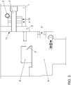
Figure 3 shows a section along the vertical plane of the detail offigure 1 in the closed position; -
Figure 4 shows the section offigure 2 in the open position; -
Figure 5 shows a top view of a section of the elements of the machine. - With reference to
figures 1 ,2 and3 , in general terms the following are represented: - the tightening means 1, positioned on the coupling interface
2, in the closed position, with the tighteningscrews 3 highlighted and theactuators 4, positioned within said tightening means 1 and spaced apart in relation to thescrews 3; - the
supply channel 5 of the fluid of theactuators 4 and thechambers 10 thereof. - the
lifting mechanism 7 of thecoupling interface 2; - the
wall 12 of the machine and thelongitudinal member 8
whereupon, upon closing, the sheet-pressingtools 6 fit together, by means of the guidance of aninclined plane 9; - the
housing 11 of the gripping means used for the removal and/or the insertion of thetools 6. - In particular, with reference to
figures 1 ,2 and3 , the state of the machine when the release device remains in the tightened position will now be described. - The tightening means 1 is in contact with the
coupling interface 2; theactuators 4 are not under pressure, therefore the tightening means 1 are maintained in position be the tightening force exerted by thescrews 3. The friction between the surfaces in contact with theinterface 2 respectively with the tightening means 1 and thewall 12, therefore prevents their vertical translation and, consequently, the horizontal sliding of thetool 6 is prevented; it remains fixed to thelongitudinal member 8 by virtue of theinclined plane 9. - In detail, in
figure 4 it can be seen that theactuators 4 are in contact with thewall 12; saidactuators 4 andscrews 3 are positioned along a guide within theinterface 2, in such a way that the interface can advantageously slide along the vertical direction. - Specifically, this guide may comprise a cavity, for example passing through the
interface 2 itself. - In a preferred variant, the
screws 3 are preferably arranged in an alternate manner in relation to theactuators 4 but spaced apart in relation to them, in order to make it possible, upon their actuation, to obtain a minimum degree of play between theinterface 2, the tightening means 1 andwall 12, freeing thetool 6, by means of a minimum displacement of the tightening means 1 along a preferred direction determined byactuators 4. - Making reference now to
figure 4 , the state of the device of the invention will be described, when theactuators 4 are actuated by the fluid supplied by thepipe 5. The increase in the pressure of the fluid within thechambers 10 generates a force that is opposed to that elastic force of the tightening exerted by thescrews 3. - The consequent displacement of the tightening means 1 advantageously produces a minimum degree of play between the surfaces of the
interface 2, of the tightening means 1 itself and of thewall 12, allowing saidinterface 2 to be lifted vertically by themechanism 7. Thetool 6 can therefore be removed and/or replaced by horizontally sliding it, by means of gripping means capable of being engaged within thehousing 11. - The sheet-pressing
tool 6 protrudes by a small extent, e. g. 0,04 to 0,06 mm relative to thewall 12. - The section in
figure 5 shows more clearly the arrangement of thescrews 3 and of theactuators 4, in a preferred configuration, highlighting the modular character of thecoupling interface 2. - In general terms, it is clear that the problem mentioned above, of a quite complex nature, is resolved in a simple and ingenious manner by the device described; indeed it can, by means of a combination of simple kinematics, and some technical shrewdness, render precise, reliable and automatic a process that involves numerous drawbacks if performed conventionally, making it possible to easily and quickly take up any play between surfaces in contact.
- The present invention has been described, for illustrative but non-limiting purposes, according to preferred embodiments thereof, but it is to be understood that variations and/or modifications can be made by experts in the field, without for this reason going beyond the relative scope of protection.
Claims (11)
- Release device refined for industrial machine for bending metal elements by means of a plurality of sheet-pressing tools (6) arranged over a supporting frame, said machine comprising a longitudinal member (8) to which said sheet-pressing tools are coupled (6) by means of an inclined interface (9),
said device comprising clamping means (1), and a modular coupling interface (2) configured to be located in between said clamping means (1) and a wall (12) of the machine,
said interface (2) being configured for keeping said tools (6) in a locked position,
said clamping means (1) comprising a plurality of clamping elements (3), suitable for locking the interface (2) to the upper surface of the sheet-pressing tools (6) and arranged in alternation to a plurality of actuators (4),
said actuators (4) being configured to exert on the wall (12), when in action, a force opposed to the force exerted by said clamping elements (3) therefore allowing the horizontal displacement of the clamping means (1),
this displacement allowing the interface (2) to move vertically to allow the removal of the sheet-pressing tool (6). - Release device, according to claim 1, characterized in that said coupling interface (2) comprises at least one plate configured to be coupled to at least one respective sheet-pressing tool (6) to be locked.
- Release device, according to claim 1 or 2, characterized in that said clamping elements (3) comprise clamping screws.
- Release device, according to claim 3, characterized in that said clamping screws (3) are configured to be received in respective cavities within the said modular interface (2) and the said industrial machine.
- Release device, according to one or more of the preceding claims, characterized in that said clamping elements (3) are equidistant each other.
- Release device, according to claim 1, characterized in that said actuators (4) are of hydraulic and/or pneumatic type.
- Release device, according to claim 6, characterized in that the actuators (4) comprise chambers (10) and are operated by supplying an appropriate fluid through one or more supply channels (5) to the chambers (10).
- Release device, according to each of the preceding claims, characterized by the presence of lifting mechanisms for each of the plates of the coupling interface (2).
- Industrial machine for bending metal elements by means of a plurality of sheet-pressing tools (6) arranged over a supporting frame, said machine comprising a longitudinal member (8) to which said sheet-pressing tools (6) are coupled by means of an inclined interface (9), characterized in that it includes a release device according to one of the claims 1 to 8.
- Industrial machine, according to claim 9, characterized in comprising a wall (12) suitable to keep said coupling interface (2) locked in place when said actuators (4) are not in action against said wall (12).
- Industrial machine, according to claim 10, characterized in that the wall (12) comprises a plurality of cavities suitable to receive respective clamping elements (3) of the release device.
Applications Claiming Priority (1)
| Application Number | Priority Date | Filing Date | Title |
|---|---|---|---|
| IT102018000020824A IT201800020824A1 (en) | 2018-12-21 | 2018-12-21 | Release device for an industrial machine for the bending of metal elements |
Publications (2)
| Publication Number | Publication Date |
|---|---|
| EP3670016A1 true EP3670016A1 (en) | 2020-06-24 |
| EP3670016B1 EP3670016B1 (en) | 2024-02-28 |
Family
ID=65861646
Family Applications (1)
| Application Number | Title | Priority Date | Filing Date |
|---|---|---|---|
| EP19218662.5A Active EP3670016B1 (en) | 2018-12-21 | 2019-12-20 | Release device for an industrial machine for the bending of metal elements |
Country Status (3)
| Country | Link |
|---|---|
| US (1) | US11446724B2 (en) |
| EP (1) | EP3670016B1 (en) |
| IT (1) | IT201800020824A1 (en) |
Cited By (1)
| Publication number | Priority date | Publication date | Assignee | Title |
|---|---|---|---|---|
| CN114054605A (en) * | 2021-10-27 | 2022-02-18 | 广州连捷精密技术有限公司 | Small-size iron-clad riveting machine |
Citations (4)
| Publication number | Priority date | Publication date | Assignee | Title |
|---|---|---|---|---|
| EP0682996A2 (en) * | 1994-02-10 | 1995-11-22 | Balaxman Oy | Method and apparatus in a bending machine |
| US5996389A (en) * | 1996-09-07 | 1999-12-07 | Eht Werkzeugmaschinen Gmbh | Machining center for processing flat workpieces with a segment distributed hold-down |
| CH700207A1 (en) * | 2009-01-06 | 2010-07-15 | Bystronic Laser Ag | Tool i.e. bending tool, fixing device for work piece bending machine, has clamping device including pressure piston to directly or indirectly fix tool, and pressure generator generating hydraulic pressure for operating pressure piston |
| WO2013001491A1 (en) * | 2011-06-30 | 2013-01-03 | Xp Technology S.R.L. | Panel bending machine with improved blocking/release means |
-
2018
- 2018-12-21 IT IT102018000020824A patent/IT201800020824A1/en unknown
-
2019
- 2019-12-20 US US16/721,993 patent/US11446724B2/en active Active
- 2019-12-20 EP EP19218662.5A patent/EP3670016B1/en active Active
Patent Citations (4)
| Publication number | Priority date | Publication date | Assignee | Title |
|---|---|---|---|---|
| EP0682996A2 (en) * | 1994-02-10 | 1995-11-22 | Balaxman Oy | Method and apparatus in a bending machine |
| US5996389A (en) * | 1996-09-07 | 1999-12-07 | Eht Werkzeugmaschinen Gmbh | Machining center for processing flat workpieces with a segment distributed hold-down |
| CH700207A1 (en) * | 2009-01-06 | 2010-07-15 | Bystronic Laser Ag | Tool i.e. bending tool, fixing device for work piece bending machine, has clamping device including pressure piston to directly or indirectly fix tool, and pressure generator generating hydraulic pressure for operating pressure piston |
| WO2013001491A1 (en) * | 2011-06-30 | 2013-01-03 | Xp Technology S.R.L. | Panel bending machine with improved blocking/release means |
Cited By (2)
| Publication number | Priority date | Publication date | Assignee | Title |
|---|---|---|---|---|
| CN114054605A (en) * | 2021-10-27 | 2022-02-18 | 广州连捷精密技术有限公司 | Small-size iron-clad riveting machine |
| CN114054605B (en) * | 2021-10-27 | 2024-06-11 | 广东连捷精密技术有限公司 | Small iron shell riveting machine |
Also Published As
| Publication number | Publication date |
|---|---|
| US20200222961A1 (en) | 2020-07-16 |
| US11446724B2 (en) | 2022-09-20 |
| EP3670016B1 (en) | 2024-02-28 |
| IT201800020824A1 (en) | 2020-06-21 |
Similar Documents
| Publication | Publication Date | Title |
|---|---|---|
| CN106232253B (en) | Metal sheet bending machine | |
| CN113795340B (en) | Metal plate bending machine | |
| EP3670016A1 (en) | Release device for an industrial machine for the bending of metal elements | |
| US11745241B2 (en) | Bending machine for metal sheets with a tools' magazine | |
| CN112404171B (en) | Straightener, maintenance device and method for making straightening roller accessible for maintaining straightener | |
| ITMI991796A1 (en) | MACHINE TOOL FOR WOODWORKING SUITABLE FOR WORKING PIECES OF VARIABLE DIMENSIONS AND COMPLEX SHAPES AND RELATED METHOD | |
| CN111971132B (en) | Production device with tool changing unit and clamping jaws and method for changing tools | |
| US11167336B2 (en) | Actuating device for upper sheet-pressing tools of an industrial machine for the bending of metal elements | |
| RU2663673C1 (en) | Radial forging machine | |
| ITMO20060146A1 (en) | MACHINE TOOL | |
| US10281440B2 (en) | Clamping device for a sample preparation | |
| AT515953B1 (en) | Machining center for processing flat objects | |
| KR20230048540A (en) | Substrate holding hand and substrate transfer robot | |
| AT409681B (en) | Device for fixing semiconductor substrates in a mutually aligned reference position | |
| GB2145022A (en) | A riveter | |
| KR20250134270A (en) | Terminal pin bending device for electronic components | |
| DE29924137U1 (en) | Linear transfer device for an assembly machine | |
| US20050227840A1 (en) | Device and method for the transport of work pieces | |
| IT201800020821A1 (en) | AUXILIARY SHEET-PRESSING TOOL FOR A BENDING MACHINE FOR METAL SHEETS AND OTHER METAL ELEMENTS, AND SELF-ADJUSTING COUPLING AND BENDING MACHINE PROVIDED WITH SUCH AUXILIARY SHEET-PRESSING TOOL | |
| JP2007137572A (en) | Palletizing device | |
| EP3034270A1 (en) | Thermoforming apparatus with loading device |
Legal Events
| Date | Code | Title | Description |
|---|---|---|---|
| PUAI | Public reference made under article 153(3) epc to a published international application that has entered the european phase |
Free format text: ORIGINAL CODE: 0009012 |
|
| STAA | Information on the status of an ep patent application or granted ep patent |
Free format text: STATUS: THE APPLICATION HAS BEEN PUBLISHED |
|
| AK | Designated contracting states |
Kind code of ref document: A1 Designated state(s): AL AT BE BG CH CY CZ DE DK EE ES FI FR GB GR HR HU IE IS IT LI LT LU LV MC MK MT NL NO PL PT RO RS SE SI SK SM TR |
|
| AX | Request for extension of the european patent |
Extension state: BA ME |
|
| STAA | Information on the status of an ep patent application or granted ep patent |
Free format text: STATUS: REQUEST FOR EXAMINATION WAS MADE |
|
| 17P | Request for examination filed |
Effective date: 20201208 |
|
| RBV | Designated contracting states (corrected) |
Designated state(s): AL AT BE BG CH CY CZ DE DK EE ES FI FR GB GR HR HU IE IS IT LI LT LU LV MC MK MT NL NO PL PT RO RS SE SI SK SM TR |
|
| STAA | Information on the status of an ep patent application or granted ep patent |
Free format text: STATUS: EXAMINATION IS IN PROGRESS |
|
| 17Q | First examination report despatched |
Effective date: 20210607 |
|
| GRAP | Despatch of communication of intention to grant a patent |
Free format text: ORIGINAL CODE: EPIDOSNIGR1 |
|
| STAA | Information on the status of an ep patent application or granted ep patent |
Free format text: STATUS: GRANT OF PATENT IS INTENDED |
|
| INTG | Intention to grant announced |
Effective date: 20231103 |
|
| GRAS | Grant fee paid |
Free format text: ORIGINAL CODE: EPIDOSNIGR3 |
|
| GRAA | (expected) grant |
Free format text: ORIGINAL CODE: 0009210 |
|
| STAA | Information on the status of an ep patent application or granted ep patent |
Free format text: STATUS: THE PATENT HAS BEEN GRANTED |
|
| AK | Designated contracting states |
Kind code of ref document: B1 Designated state(s): AL AT BE BG CH CY CZ DE DK EE ES FI FR GB GR HR HU IE IS IT LI LT LU LV MC MK MT NL NO PL PT RO RS SE SI SK SM TR |
|
| REG | Reference to a national code |
Ref country code: GB Ref legal event code: FG4D |
|
| REG | Reference to a national code |
Ref country code: CH Ref legal event code: EP |
|
| P01 | Opt-out of the competence of the unified patent court (upc) registered |
Effective date: 20240207 |
|
| REG | Reference to a national code |
Ref country code: DE Ref legal event code: R096 Ref document number: 602019047259 Country of ref document: DE |
|
| REG | Reference to a national code |
Ref country code: IE Ref legal event code: FG4D |
|
| REG | Reference to a national code |
Ref country code: LT Ref legal event code: MG9D |
|
| PG25 | Lapsed in a contracting state [announced via postgrant information from national office to epo] |
Ref country code: IS Free format text: LAPSE BECAUSE OF FAILURE TO SUBMIT A TRANSLATION OF THE DESCRIPTION OR TO PAY THE FEE WITHIN THE PRESCRIBED TIME-LIMIT Effective date: 20240628 |
|
| REG | Reference to a national code |
Ref country code: NL Ref legal event code: MP Effective date: 20240228 |
|
| PG25 | Lapsed in a contracting state [announced via postgrant information from national office to epo] |
Ref country code: LT Free format text: LAPSE BECAUSE OF FAILURE TO SUBMIT A TRANSLATION OF THE DESCRIPTION OR TO PAY THE FEE WITHIN THE PRESCRIBED TIME-LIMIT Effective date: 20240228 |
|
| PG25 | Lapsed in a contracting state [announced via postgrant information from national office to epo] |
Ref country code: GR Free format text: LAPSE BECAUSE OF FAILURE TO SUBMIT A TRANSLATION OF THE DESCRIPTION OR TO PAY THE FEE WITHIN THE PRESCRIBED TIME-LIMIT Effective date: 20240529 |
|
| PG25 | Lapsed in a contracting state [announced via postgrant information from national office to epo] |
Ref country code: NL Free format text: LAPSE BECAUSE OF FAILURE TO SUBMIT A TRANSLATION OF THE DESCRIPTION OR TO PAY THE FEE WITHIN THE PRESCRIBED TIME-LIMIT Effective date: 20240228 Ref country code: HR Free format text: LAPSE BECAUSE OF FAILURE TO SUBMIT A TRANSLATION OF THE DESCRIPTION OR TO PAY THE FEE WITHIN THE PRESCRIBED TIME-LIMIT Effective date: 20240228 Ref country code: RS Free format text: LAPSE BECAUSE OF FAILURE TO SUBMIT A TRANSLATION OF THE DESCRIPTION OR TO PAY THE FEE WITHIN THE PRESCRIBED TIME-LIMIT Effective date: 20240528 |
|
| PG25 | Lapsed in a contracting state [announced via postgrant information from national office to epo] |
Ref country code: ES Free format text: LAPSE BECAUSE OF FAILURE TO SUBMIT A TRANSLATION OF THE DESCRIPTION OR TO PAY THE FEE WITHIN THE PRESCRIBED TIME-LIMIT Effective date: 20240228 |
|
| PG25 | Lapsed in a contracting state [announced via postgrant information from national office to epo] |
Ref country code: RS Free format text: LAPSE BECAUSE OF FAILURE TO SUBMIT A TRANSLATION OF THE DESCRIPTION OR TO PAY THE FEE WITHIN THE PRESCRIBED TIME-LIMIT Effective date: 20240528 Ref country code: NO Free format text: LAPSE BECAUSE OF FAILURE TO SUBMIT A TRANSLATION OF THE DESCRIPTION OR TO PAY THE FEE WITHIN THE PRESCRIBED TIME-LIMIT Effective date: 20240528 Ref country code: NL Free format text: LAPSE BECAUSE OF FAILURE TO SUBMIT A TRANSLATION OF THE DESCRIPTION OR TO PAY THE FEE WITHIN THE PRESCRIBED TIME-LIMIT Effective date: 20240228 Ref country code: LT Free format text: LAPSE BECAUSE OF FAILURE TO SUBMIT A TRANSLATION OF THE DESCRIPTION OR TO PAY THE FEE WITHIN THE PRESCRIBED TIME-LIMIT Effective date: 20240228 Ref country code: IS Free format text: LAPSE BECAUSE OF FAILURE TO SUBMIT A TRANSLATION OF THE DESCRIPTION OR TO PAY THE FEE WITHIN THE PRESCRIBED TIME-LIMIT Effective date: 20240628 Ref country code: HR Free format text: LAPSE BECAUSE OF FAILURE TO SUBMIT A TRANSLATION OF THE DESCRIPTION OR TO PAY THE FEE WITHIN THE PRESCRIBED TIME-LIMIT Effective date: 20240228 Ref country code: GR Free format text: LAPSE BECAUSE OF FAILURE TO SUBMIT A TRANSLATION OF THE DESCRIPTION OR TO PAY THE FEE WITHIN THE PRESCRIBED TIME-LIMIT Effective date: 20240529 Ref country code: FI Free format text: LAPSE BECAUSE OF FAILURE TO SUBMIT A TRANSLATION OF THE DESCRIPTION OR TO PAY THE FEE WITHIN THE PRESCRIBED TIME-LIMIT Effective date: 20240228 Ref country code: ES Free format text: LAPSE BECAUSE OF FAILURE TO SUBMIT A TRANSLATION OF THE DESCRIPTION OR TO PAY THE FEE WITHIN THE PRESCRIBED TIME-LIMIT Effective date: 20240228 Ref country code: BG Free format text: LAPSE BECAUSE OF FAILURE TO SUBMIT A TRANSLATION OF THE DESCRIPTION OR TO PAY THE FEE WITHIN THE PRESCRIBED TIME-LIMIT Effective date: 20240228 |
|
| PG25 | Lapsed in a contracting state [announced via postgrant information from national office to epo] |
Ref country code: PL Free format text: LAPSE BECAUSE OF FAILURE TO SUBMIT A TRANSLATION OF THE DESCRIPTION OR TO PAY THE FEE WITHIN THE PRESCRIBED TIME-LIMIT Effective date: 20240228 Ref country code: PT Free format text: LAPSE BECAUSE OF FAILURE TO SUBMIT A TRANSLATION OF THE DESCRIPTION OR TO PAY THE FEE WITHIN THE PRESCRIBED TIME-LIMIT Effective date: 20240628 |
|
| REG | Reference to a national code |
Ref country code: AT Ref legal event code: MK05 Ref document number: 1660778 Country of ref document: AT Kind code of ref document: T Effective date: 20240228 |
|
| PG25 | Lapsed in a contracting state [announced via postgrant information from national office to epo] |
Ref country code: SE Free format text: LAPSE BECAUSE OF FAILURE TO SUBMIT A TRANSLATION OF THE DESCRIPTION OR TO PAY THE FEE WITHIN THE PRESCRIBED TIME-LIMIT Effective date: 20240228 Ref country code: PT Free format text: LAPSE BECAUSE OF FAILURE TO SUBMIT A TRANSLATION OF THE DESCRIPTION OR TO PAY THE FEE WITHIN THE PRESCRIBED TIME-LIMIT Effective date: 20240628 Ref country code: PL Free format text: LAPSE BECAUSE OF FAILURE TO SUBMIT A TRANSLATION OF THE DESCRIPTION OR TO PAY THE FEE WITHIN THE PRESCRIBED TIME-LIMIT Effective date: 20240228 Ref country code: LV Free format text: LAPSE BECAUSE OF FAILURE TO SUBMIT A TRANSLATION OF THE DESCRIPTION OR TO PAY THE FEE WITHIN THE PRESCRIBED TIME-LIMIT Effective date: 20240228 |
|
| PG25 | Lapsed in a contracting state [announced via postgrant information from national office to epo] |
Ref country code: DK Free format text: LAPSE BECAUSE OF FAILURE TO SUBMIT A TRANSLATION OF THE DESCRIPTION OR TO PAY THE FEE WITHIN THE PRESCRIBED TIME-LIMIT Effective date: 20240228 |
|
| PG25 | Lapsed in a contracting state [announced via postgrant information from national office to epo] |
Ref country code: SM Free format text: LAPSE BECAUSE OF FAILURE TO SUBMIT A TRANSLATION OF THE DESCRIPTION OR TO PAY THE FEE WITHIN THE PRESCRIBED TIME-LIMIT Effective date: 20240228 |
|
| PG25 | Lapsed in a contracting state [announced via postgrant information from national office to epo] |
Ref country code: EE Free format text: LAPSE BECAUSE OF FAILURE TO SUBMIT A TRANSLATION OF THE DESCRIPTION OR TO PAY THE FEE WITHIN THE PRESCRIBED TIME-LIMIT Effective date: 20240228 Ref country code: CZ Free format text: LAPSE BECAUSE OF FAILURE TO SUBMIT A TRANSLATION OF THE DESCRIPTION OR TO PAY THE FEE WITHIN THE PRESCRIBED TIME-LIMIT Effective date: 20240228 |
|
| PG25 | Lapsed in a contracting state [announced via postgrant information from national office to epo] |
Ref country code: AT Free format text: LAPSE BECAUSE OF FAILURE TO SUBMIT A TRANSLATION OF THE DESCRIPTION OR TO PAY THE FEE WITHIN THE PRESCRIBED TIME-LIMIT Effective date: 20240228 |
|
| PG25 | Lapsed in a contracting state [announced via postgrant information from national office to epo] |
Ref country code: SK Free format text: LAPSE BECAUSE OF FAILURE TO SUBMIT A TRANSLATION OF THE DESCRIPTION OR TO PAY THE FEE WITHIN THE PRESCRIBED TIME-LIMIT Effective date: 20240228 |
|
| PG25 | Lapsed in a contracting state [announced via postgrant information from national office to epo] |
Ref country code: SM Free format text: LAPSE BECAUSE OF FAILURE TO SUBMIT A TRANSLATION OF THE DESCRIPTION OR TO PAY THE FEE WITHIN THE PRESCRIBED TIME-LIMIT Effective date: 20240228 Ref country code: SK Free format text: LAPSE BECAUSE OF FAILURE TO SUBMIT A TRANSLATION OF THE DESCRIPTION OR TO PAY THE FEE WITHIN THE PRESCRIBED TIME-LIMIT Effective date: 20240228 Ref country code: RO Free format text: LAPSE BECAUSE OF FAILURE TO SUBMIT A TRANSLATION OF THE DESCRIPTION OR TO PAY THE FEE WITHIN THE PRESCRIBED TIME-LIMIT Effective date: 20240228 Ref country code: EE Free format text: LAPSE BECAUSE OF FAILURE TO SUBMIT A TRANSLATION OF THE DESCRIPTION OR TO PAY THE FEE WITHIN THE PRESCRIBED TIME-LIMIT Effective date: 20240228 Ref country code: DK Free format text: LAPSE BECAUSE OF FAILURE TO SUBMIT A TRANSLATION OF THE DESCRIPTION OR TO PAY THE FEE WITHIN THE PRESCRIBED TIME-LIMIT Effective date: 20240228 Ref country code: CZ Free format text: LAPSE BECAUSE OF FAILURE TO SUBMIT A TRANSLATION OF THE DESCRIPTION OR TO PAY THE FEE WITHIN THE PRESCRIBED TIME-LIMIT Effective date: 20240228 Ref country code: AT Free format text: LAPSE BECAUSE OF FAILURE TO SUBMIT A TRANSLATION OF THE DESCRIPTION OR TO PAY THE FEE WITHIN THE PRESCRIBED TIME-LIMIT Effective date: 20240228 |
|
| REG | Reference to a national code |
Ref country code: DE Ref legal event code: R097 Ref document number: 602019047259 Country of ref document: DE |
|
| PLBE | No opposition filed within time limit |
Free format text: ORIGINAL CODE: 0009261 |
|
| STAA | Information on the status of an ep patent application or granted ep patent |
Free format text: STATUS: NO OPPOSITION FILED WITHIN TIME LIMIT |
|
| 26N | No opposition filed |
Effective date: 20241129 |
|
| PG25 | Lapsed in a contracting state [announced via postgrant information from national office to epo] |
Ref country code: SI Free format text: LAPSE BECAUSE OF FAILURE TO SUBMIT A TRANSLATION OF THE DESCRIPTION OR TO PAY THE FEE WITHIN THE PRESCRIBED TIME-LIMIT Effective date: 20240228 |
|
| PG25 | Lapsed in a contracting state [announced via postgrant information from national office to epo] |
Ref country code: MC Free format text: LAPSE BECAUSE OF FAILURE TO SUBMIT A TRANSLATION OF THE DESCRIPTION OR TO PAY THE FEE WITHIN THE PRESCRIBED TIME-LIMIT Effective date: 20240228 |
|
| REG | Reference to a national code |
Ref country code: CH Ref legal event code: PL |
|
| PG25 | Lapsed in a contracting state [announced via postgrant information from national office to epo] |
Ref country code: LU Free format text: LAPSE BECAUSE OF NON-PAYMENT OF DUE FEES Effective date: 20241220 |
|
| REG | Reference to a national code |
Ref country code: BE Ref legal event code: MM Effective date: 20241231 |
|
| PG25 | Lapsed in a contracting state [announced via postgrant information from national office to epo] |
Ref country code: BE Free format text: LAPSE BECAUSE OF NON-PAYMENT OF DUE FEES Effective date: 20241231 |
|
| PG25 | Lapsed in a contracting state [announced via postgrant information from national office to epo] |
Ref country code: FR Free format text: LAPSE BECAUSE OF NON-PAYMENT OF DUE FEES Effective date: 20241231 |
|
| PG25 | Lapsed in a contracting state [announced via postgrant information from national office to epo] |
Ref country code: CH Free format text: LAPSE BECAUSE OF NON-PAYMENT OF DUE FEES Effective date: 20241231 |
|
| PG25 | Lapsed in a contracting state [announced via postgrant information from national office to epo] |
Ref country code: IE Free format text: LAPSE BECAUSE OF NON-PAYMENT OF DUE FEES Effective date: 20241220 |
|
| PGFP | Annual fee paid to national office [announced via postgrant information from national office to epo] |
Ref country code: DE Payment date: 20251104 Year of fee payment: 7 |
|
| PGFP | Annual fee paid to national office [announced via postgrant information from national office to epo] |
Ref country code: GB Payment date: 20251114 Year of fee payment: 7 |
|
| PGFP | Annual fee paid to national office [announced via postgrant information from national office to epo] |
Ref country code: IT Payment date: 20251121 Year of fee payment: 7 |