EP3669708A1 - Présentoir pliable en matériau plat et procédé d'assemblage de ce présentoir pliable - Google Patents
Présentoir pliable en matériau plat et procédé d'assemblage de ce présentoir pliable Download PDFInfo
- Publication number
- EP3669708A1 EP3669708A1 EP19216671.8A EP19216671A EP3669708A1 EP 3669708 A1 EP3669708 A1 EP 3669708A1 EP 19216671 A EP19216671 A EP 19216671A EP 3669708 A1 EP3669708 A1 EP 3669708A1
- Authority
- EP
- European Patent Office
- Prior art keywords
- fold lines
- central portion
- lateral end
- display stand
- sheet
- Prior art date
- Legal status (The legal status is an assumption and is not a legal conclusion. Google has not performed a legal analysis and makes no representation as to the accuracy of the status listed.)
- Withdrawn
Links
Images


Classifications
-
- A—HUMAN NECESSITIES
- A47—FURNITURE; DOMESTIC ARTICLES OR APPLIANCES; COFFEE MILLS; SPICE MILLS; SUCTION CLEANERS IN GENERAL
- A47F—SPECIAL FURNITURE, FITTINGS, OR ACCESSORIES FOR SHOPS, STOREHOUSES, BARS, RESTAURANTS OR THE LIKE; PAYING COUNTERS
- A47F5/00—Show stands, hangers, or shelves characterised by their constructional features
- A47F5/10—Adjustable or foldable or dismountable display stands
- A47F5/11—Adjustable or foldable or dismountable display stands made of cardboard, paper or the like
- A47F5/112—Adjustable or foldable or dismountable display stands made of cardboard, paper or the like hand-folded from sheet material
- A47F5/116—Shelving racks
Definitions
- the present invention generally finds application in the field of paper processing and advertising and particularly relates to a folding display stand.
- Folding stands have been long known to be used in small- and large-scale retail applications to display various types of products, such as cosmetic or pharmaceutical products.
- a first drawback of this display stands is their very large size in the mounted or folded state.
- US2011011814 discloses a product display stand formed with a single specially shaped cardboard panel and having a single shelf.
- the panel comprises a substantially rectangular main portion having a pair of foldable side edges formed by corresponding vertical fold lines and an upper portion that extends upwards from a horizontal fold line located on the top edge of the top panel.
- This stand has various panels and folds, as well as various joints and mountings which stiffen its structure.
- EP3213660 , US2017231404 and ES2393026 disclose folding display stands which are formed each from a plurality of panels in mutually coupled relationship to define a foldable structure adapted to alternate from a collapsed storage configuration to an operating configuration in which the structure is able to stand.
- a first drawback of these display stands, and of prior art display stands in general, is that they have complex structures in terms of both numbers of panels in use and fold lines to be formed to obtain the structure in the operating configuration.
- the technical problem addressed by the present invention is to provide a folding display stand that can be easily manufactured, and assembled and has a sturdy construction.
- the object of the present invention is to obviate the above drawback, by providing a folding display stand that is highly efficient and relatively cost-effective.
- a particular object of the present invention is to provide a folding display stand of the aforementioned type that affords simple manufacture and assembly.
- a further object of the present invention is to provide a folding display stand that has a stiff structure, suitable to support the articles on display.
- Yet another object of the present invention is to provide a folding display stand of the aforementioned type that can be easily folded and stacked.
- a further object the present invention is to provide a folding stand of the aforementioned type that provides stable support to the products on display.
- a folding display stand made of a sheet material as defined in claim 1, which comprises at least one substantially flat and vertical rear wall, at least a pair of substantially vertical side walls and a plurality of substantially horizontal shelves between the side walls.
- the rear wall, the side walls and the shelves are simply formed from a pair of sheet elements derived from a single sheet of cardboard or similar material, i.e. a front sheet element and a rear sheet element respectively, which are coupled together to define a foldable structure that is able to alternate from an idle configuration with the sheet elements in mutually overlapping relationship to an operating configuration with the sheet elements in mutually spaced relationship and the shelves in vertical superimposed relationship.
- the front element comprises a central portion and two lateral end portions defined by first fold lines and the rear element comprises a central portion and two lateral end portions defined by second fold lines.
- the shelves are formed from the central portion of the front element which is cut out to form at least two flat panels and is folded along respective third fold lines substantially perpendicular to the first and the second fold lines.
- the display stand has the advantage of being particularly simple to form, assemble and collapse.
- this structure is particularly stiff and sturdy, thereby providing stable support to the products on display.
- the invention relates to a method of assembling the aforementioned display stand, as defined in claim 10.
- a folding display stand generally referenced by numeral 1, which is made of a sheet material and comprises at least one substantially flat and vertical rear wall 2, at least a pair of substantially vertical side walls 3', 3" and a plurality of substantially horizontal shelves 4', 4" interposed between the side walls 3', 3".
- the display stand 1 may be intended for use in shops or other points of sale for displaying of a multiplicity of products or articles for sale, such as cosmetics, pharmaceuticals, stationery articles, candies or other similar products.
- the rear wall 2, the side walls 3', 3" and the shelves 4', 4" are simply formed from a pair of sheet elements derived from a single sheet of cardboard or similar material.
- the pair of sheet elements i.e. a front sheet element (6) and a rear sheet element (7) respectively, are coupled together to define a foldable structure that can be alternated from an idle configuration with the sheet elements 6, 7 in mutually overlapping relationship, as shown in FIG. 3 , to an operating configuration with the elements 6, 7 in mutually spaced relationship and the shelves 4', 4" in vertically superimposed relationship, as shown in FIG. 1 .
- the term "idle configuration" is intended to designate a collapsed configuration in which the sheet elements 6, 7 overlap to form a collapsed and flattened structure during storage to minimize bulk.
- operating configuration is intended to designate a configuration in which the display stand 1 forms a deployed structure for display of the products or articles, which is vertically arranged, substantially orthogonal to a support surface.
- the sheet material of the elements 6, 7 may be selected from the group comprising paper, cardboard, plastic or similar material, such as copper, as long as it has high ductility properties.
- the front sheet element 6 is adapted to define the side walls 3', 3" and the shelves 4', 4" and the rear sheet element 7 is adapted to define the rear wall 2.
- the front element 6 has a central portion 8 and two lateral end portions 9A, 9B defined by first fold lines 10A, 10B.
- the rear element 7 comprises a central portion 11 and two lateral end portions 12A, 12B defined by second fold lines 13A, 13B, as best shown in FIGS. 6 and 7 .
- the shelves 4', 4" are formed from the central portion 8 of the front element 6, which is cut out to form at least two flat panels 14A, 14B and is folded along respective third fold lines 15A, 15B substantially perpendicular to the first fold lines 10A, 10B and the second fold lines 13A, 13B.
- the lateral end portions 9A, 9B; 12A, 12B of the elements 6, 7 are mutually overlapped and coupled by fastening means to maintain the first fold lines 10A, 10B and the second fold lines 13A, 13B parallel to and spaced apart from each other to stiffen the foldable structure.
- the flat panels 14A, 14B can be folded along their respective third fold lines 15A, 15B into the operating configuration and, once folded, are coupled to the central portion 11 of the rear element 7.
- the flat panels 14A, 14B are also substantially perpendicular to the first fold lines 10A, 10B and the second fold lines 13A, 13B to further stiffen the structure in the operating configuration.
- each foldable flat panel 14A, 14B of the front element 6 has a free edge 16A, 16B located on the side opposite to that of the third fold lines 15A, 15B and adapted to be coupled to the central portion 11 of the rear element 7.
- the front panel 6 has a pair of projections 17A, 17B formed along the free edge 16A, 16B, that can fit into corresponding aligned slits 18A, 18B formed in the central portion 11 of the rear element 7, as further discussed below.
- the front element 6 is equipped with a bottom edge 19 which usually rests on the ground or a shelf or counter when the display stand 1 is in the operating state.
- one of the third fold lines 15A belonging to the first foldable panel 14A is spaced apart from the bottom edge 19 of the front panel 6 to thereby define a first crosspiece 20A that stiffens the foldable structure when the latter is in the operating state.
- the other third fold line 15B belonging to the second foldable panel 14B is spaced apart from the free edge 16A of the first panel 14A to thereby define a second crosspiece 20B that further stiffens the structure of the display stand 1.
- the rear element 7 also has a bottom edge 21 that usually rests on the ground, a shelf or a counter when the structure of the display stand 1 is in the operating state, like the bottom edge 19 of the front element 6.
- the first pair of aligned slits 18A formed in the central portion 11 of the rear element 7 are parallel to the bottom edge 21 and spaced apart therefrom at a short distance, equal to the height of the first crosspiece 20A.
- the central portion 11 of the rear element 7 further comprises a second pair of slits 18B substantially aligned and parallel to the bottom edge 21 of the element 7 and spaced apart from the first pair of slits 18A.
- the first and second pairs of slits 18A, 18B are formed in such a manner that, when the display stand 1 is being assembled, the first pair of projections 17A of the first panel 14A fit into the first pair of slits 18A of the central portion 11 of the rear element 7 respectively, and the second pair of projections 17B of the second panel 14B fit into the second pair of slits 18B of the central portion 11 of the rear element 7.
- the lateral end portions 12A, 12B of the rear element 7 are formed in such a manner that their width is smaller than the width of the lateral end portions 9A, 9B of the front element 6.
- the invention relates to a method of assembling a display stand 1 made of sheet material as described above.
- the two lateral end portions 9A, 9B in the front element 6 are folded along the first fold lines 10A, 10B respectively, such that they will be substantially perpendicular to the central portion 8 of the same front panel 6.
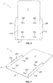
- first flat panel 14A is folded along the third fold line 15A and the second flat panel 14B is folded along the third fold line 15B, such that they will be substantially perpendicular to the central portion 8 of the front element 6, as shown in FIG. 5 .
- the first lateral end portion 12A in the rear element 7 is folded along its second fold line 13A and the second lateral end portion 12B is folded along its second fold line 13B, such that the two lateral end portions 12A, 12B are arranged substantially perpendicular to the central portion 11 of the rear element 7, as shown in FIG. 6 .
- rear element 7 may be simply coupled to the front element 6, so that:
- first flat panel 14A has been folded to form the lower shelf 4'
- second flat panel 14B has been used to form the upper shelf 4"
- the central portion 11 of the real element 7 has been used to form the rear wall 2
- the lateral end portions 9A, 9B of the front element 6 have been used to form the respective side walls 3', 3" of the display stand 1.
- the two lateral end portions 9A, 9B of the front element 6 and the two lateral end portions 12A, 12B of the rear element 7 are fixed to each other in the opposite direction, for example by bonding, stapling, or with other fastening means.
- the lateral end portions 9A, 9B; 12A, 12B of the sheet elements 6, 7 may be first folded, the rear element 7 may be later moved close to the front element 6, as shown in FIG. 8 and the respective lateral end portions 9A, 9B; 12A, 12B may be later bonded together by fastening means.
- the display stand 1 so assembled may be collapsed into the idle configuration, as shown in FIG. 3 and packaged for sale, not shown.
- the alternation from the idle configuration to the operating configuration may be performed by a user once he/she has pulled the display stand 1 out of the package and has folded the flat panels 14A, 14B to fit the respective projections 17A, 17B into the corresponding aligned slits 18A, 18B, as discussed above.
- a folding display stand 1 may be also provided, which has more than two shelves 4', 4", for example three or more.
- three or more panels 14 may be derived from the front element 6, i.e. as many as the shelves 4 to be formed, and the rear element 7 will have as many pairs of slits 18 as the shelves 4 to be formed.
- multiple projections 17 may be formed, with respective slits 18 in the central portion 11 of the rear element 7.
- the display stand structure of the invention is susceptible of a number of changes and variants, within the inventive concept as disclosed in the appended claims.
- the present invention may find application in industry, because it can be produced on an industrial scale in the paperprocessing and advertising industries.
Landscapes
- Display Racks (AREA)
- Glass Compositions (AREA)
- Polysaccharides And Polysaccharide Derivatives (AREA)
- Paper (AREA)
Applications Claiming Priority (1)
| Application Number | Priority Date | Filing Date | Title |
|---|---|---|---|
| IT102018000011165A IT201800011165A1 (it) | 2018-12-17 | 2018-12-17 | Espositore pieghevole in materiale laminare |
Publications (1)
| Publication Number | Publication Date |
|---|---|
| EP3669708A1 true EP3669708A1 (fr) | 2020-06-24 |
Family
ID=65861636
Family Applications (1)
| Application Number | Title | Priority Date | Filing Date |
|---|---|---|---|
| EP19216671.8A Withdrawn EP3669708A1 (fr) | 2018-12-17 | 2019-12-16 | Présentoir pliable en matériau plat et procédé d'assemblage de ce présentoir pliable |
Country Status (2)
| Country | Link |
|---|---|
| EP (1) | EP3669708A1 (fr) |
| IT (1) | IT201800011165A1 (fr) |
Citations (6)
| Publication number | Priority date | Publication date | Assignee | Title |
|---|---|---|---|---|
| US20110011814A1 (en) | 2009-07-16 | 2011-01-20 | Glenn Edward Moss | Merchandise display support stand |
| CN202014905U (zh) * | 2011-01-30 | 2011-10-26 | 陈力雄 | 一种新型展示架 |
| ES2393026A1 (es) | 2011-02-14 | 2012-12-17 | Tot Display, S.A | Expositor desplegable. |
| US20170231404A1 (en) | 2016-02-15 | 2017-08-17 | KapStone Container Corporation | Cabinet |
| EP3213660A1 (fr) | 2016-02-25 | 2017-09-06 | Sonoco Development, Inc. | Système de rayonnage à deux composants |
| DE102016216129A1 (de) * | 2016-08-26 | 2018-03-01 | Hans-Peter Stange | Pappregal und Verfahren zum Aufstellen eines Pappregals |
-
2018
- 2018-12-17 IT IT102018000011165A patent/IT201800011165A1/it unknown
-
2019
- 2019-12-16 EP EP19216671.8A patent/EP3669708A1/fr not_active Withdrawn
Patent Citations (6)
| Publication number | Priority date | Publication date | Assignee | Title |
|---|---|---|---|---|
| US20110011814A1 (en) | 2009-07-16 | 2011-01-20 | Glenn Edward Moss | Merchandise display support stand |
| CN202014905U (zh) * | 2011-01-30 | 2011-10-26 | 陈力雄 | 一种新型展示架 |
| ES2393026A1 (es) | 2011-02-14 | 2012-12-17 | Tot Display, S.A | Expositor desplegable. |
| US20170231404A1 (en) | 2016-02-15 | 2017-08-17 | KapStone Container Corporation | Cabinet |
| EP3213660A1 (fr) | 2016-02-25 | 2017-09-06 | Sonoco Development, Inc. | Système de rayonnage à deux composants |
| DE102016216129A1 (de) * | 2016-08-26 | 2018-03-01 | Hans-Peter Stange | Pappregal und Verfahren zum Aufstellen eines Pappregals |
Also Published As
| Publication number | Publication date |
|---|---|
| IT201800011165A1 (it) | 2020-06-17 |
Similar Documents
| Publication | Publication Date | Title |
|---|---|---|
| US10390634B2 (en) | Modular greeting card rack | |
| US10342365B2 (en) | Hutch shelf | |
| US7882966B2 (en) | Multi-shelf paperboard display unit and method of assembling the same | |
| US2108349A (en) | Advertising device and mailing tube | |
| US20150136720A1 (en) | Display hutch and methods of assembling the same | |
| EP3379979B1 (fr) | Présentoir pliable optimisé | |
| US20190014927A1 (en) | Merchandising display having quick shelf set up | |
| CN106455809A (zh) | 用于纸板塔状展示装置的模块化结构 | |
| US12075928B2 (en) | Divided shelf for modular greeting card rack | |
| EP3669709B1 (fr) | Présentoir pliable en forme de marche et procédé d'assemblage d'un tel présentoir pliable en forme de marche | |
| CA2794001C (fr) | Ensemble pour la vente au detail avec support pliable | |
| EP3669708A1 (fr) | Présentoir pliable en matériau plat et procédé d'assemblage de ce présentoir pliable | |
| EP3643638B1 (fr) | Unité de transport pour produits alimentaires | |
| NL2003144C2 (en) | A display unit and blanks for forming said unit. | |
| JP6340883B2 (ja) | 陳列棚 | |
| JP7209457B2 (ja) | 表示体 | |
| US20220340325A1 (en) | Modular greeting card rack | |
| US20050067473A1 (en) | Convertible tray blank and container | |
| US11600207B2 (en) | Retail display header and associated assemblies | |
| GB2334202A (en) | Display unit of folded sheet material | |
| US9446869B2 (en) | Packaging band and associated packaged product | |
| AU681644B2 (en) | A display system | |
| KR20110009281A (ko) | 조립식 전시대 | |
| GB2442272A (en) | Support attachment for a sign |
Legal Events
| Date | Code | Title | Description |
|---|---|---|---|
| PUAI | Public reference made under article 153(3) epc to a published international application that has entered the european phase |
Free format text: ORIGINAL CODE: 0009012 |
|
| STAA | Information on the status of an ep patent application or granted ep patent |
Free format text: STATUS: THE APPLICATION HAS BEEN PUBLISHED |
|
| AK | Designated contracting states |
Kind code of ref document: A1 Designated state(s): AL AT BE BG CH CY CZ DE DK EE ES FI FR GB GR HR HU IE IS IT LI LT LU LV MC MK MT NL NO PL PT RO RS SE SI SK SM TR |
|
| AX | Request for extension of the european patent |
Extension state: BA ME |
|
| STAA | Information on the status of an ep patent application or granted ep patent |
Free format text: STATUS: REQUEST FOR EXAMINATION WAS MADE |
|
| 17P | Request for examination filed |
Effective date: 20210111 |
|
| RBV | Designated contracting states (corrected) |
Designated state(s): AL AT BE BG CH CY CZ DE DK EE ES FI FR GB GR HR HU IE IS IT LI LT LU LV MC MK MT NL NO PL PT RO RS SE SI SK SM TR |
|
| STAA | Information on the status of an ep patent application or granted ep patent |
Free format text: STATUS: EXAMINATION IS IN PROGRESS |
|
| 17Q | First examination report despatched |
Effective date: 20210531 |
|
| STAA | Information on the status of an ep patent application or granted ep patent |
Free format text: STATUS: THE APPLICATION IS DEEMED TO BE WITHDRAWN |
|
| 18D | Application deemed to be withdrawn |
Effective date: 20211012 |