EP3668802B1 - Soupape en matériaux solides pour récipients sous pression - Google Patents
Soupape en matériaux solides pour récipients sous pression Download PDFInfo
- Publication number
- EP3668802B1 EP3668802B1 EP18765560.0A EP18765560A EP3668802B1 EP 3668802 B1 EP3668802 B1 EP 3668802B1 EP 18765560 A EP18765560 A EP 18765560A EP 3668802 B1 EP3668802 B1 EP 3668802B1
- Authority
- EP
- European Patent Office
- Prior art keywords
- stem
- valve
- valve body
- solid matter
- circumferential
- Prior art date
- Legal status (The legal status is an assumption and is not a legal conclusion. Google has not performed a legal analysis and makes no representation as to the accuracy of the status listed.)
- Active
Links
- 239000007787 solid Substances 0.000 title claims description 20
- 238000007789 sealing Methods 0.000 claims description 42
- 239000006260 foam Substances 0.000 claims description 10
- 239000011324 bead Substances 0.000 claims description 3
- 238000007599 discharging Methods 0.000 claims description 2
- 239000012528 membrane Substances 0.000 description 20
- 239000000463 material Substances 0.000 description 5
- 230000000630 rising effect Effects 0.000 description 5
- 238000005187 foaming Methods 0.000 description 4
- 239000000443 aerosol Substances 0.000 description 3
- 230000000694 effects Effects 0.000 description 3
- -1 polyoxymethylene Polymers 0.000 description 3
- 230000001960 triggered effect Effects 0.000 description 3
- 230000015572 biosynthetic process Effects 0.000 description 2
- 238000010276 construction Methods 0.000 description 2
- 238000001746 injection moulding Methods 0.000 description 2
- 230000007246 mechanism Effects 0.000 description 2
- 239000007921 spray Substances 0.000 description 2
- 229920002725 thermoplastic elastomer Polymers 0.000 description 2
- 239000004604 Blowing Agent Substances 0.000 description 1
- 229930040373 Paraformaldehyde Natural products 0.000 description 1
- 239000004698 Polyethylene Substances 0.000 description 1
- 239000004743 Polypropylene Substances 0.000 description 1
- 229920005830 Polyurethane Foam Polymers 0.000 description 1
- 230000009471 action Effects 0.000 description 1
- 239000000853 adhesive Substances 0.000 description 1
- 230000001070 adhesive effect Effects 0.000 description 1
- 230000000903 blocking effect Effects 0.000 description 1
- 230000008859 change Effects 0.000 description 1
- 238000006243 chemical reaction Methods 0.000 description 1
- 239000012459 cleaning agent Substances 0.000 description 1
- 230000005494 condensation Effects 0.000 description 1
- 238000009833 condensation Methods 0.000 description 1
- 238000005260 corrosion Methods 0.000 description 1
- 230000007797 corrosion Effects 0.000 description 1
- 238000004132 cross linking Methods 0.000 description 1
- 238000006073 displacement reaction Methods 0.000 description 1
- 239000013013 elastic material Substances 0.000 description 1
- 238000005516 engineering process Methods 0.000 description 1
- 239000004088 foaming agent Substances 0.000 description 1
- 230000001771 impaired effect Effects 0.000 description 1
- 238000009413 insulation Methods 0.000 description 1
- 230000010354 integration Effects 0.000 description 1
- 238000000034 method Methods 0.000 description 1
- 239000000203 mixture Substances 0.000 description 1
- 239000003973 paint Substances 0.000 description 1
- 229920001281 polyalkylene Polymers 0.000 description 1
- 229920000573 polyethylene Polymers 0.000 description 1
- 229920000642 polymer Polymers 0.000 description 1
- 229920006324 polyoxymethylene Polymers 0.000 description 1
- 229920001155 polypropylene Polymers 0.000 description 1
- 239000011496 polyurethane foam Substances 0.000 description 1
- 230000008569 process Effects 0.000 description 1
- 239000000565 sealant Substances 0.000 description 1
- 239000012815 thermoplastic material Substances 0.000 description 1
- 210000002105 tongue Anatomy 0.000 description 1
- 230000007704 transition Effects 0.000 description 1
Images
Classifications
-
- B—PERFORMING OPERATIONS; TRANSPORTING
- B65—CONVEYING; PACKING; STORING; HANDLING THIN OR FILAMENTARY MATERIAL
- B65D—CONTAINERS FOR STORAGE OR TRANSPORT OF ARTICLES OR MATERIALS, e.g. BAGS, BARRELS, BOTTLES, BOXES, CANS, CARTONS, CRATES, DRUMS, JARS, TANKS, HOPPERS, FORWARDING CONTAINERS; ACCESSORIES, CLOSURES, OR FITTINGS THEREFOR; PACKAGING ELEMENTS; PACKAGES
- B65D83/00—Containers or packages with special means for dispensing contents
- B65D83/14—Containers or packages with special means for dispensing contents for delivery of liquid or semi-liquid contents by internal gaseous pressure, i.e. aerosol containers comprising propellant for a product delivered by a propellant
- B65D83/38—Details of the container body
-
- B—PERFORMING OPERATIONS; TRANSPORTING
- B65—CONVEYING; PACKING; STORING; HANDLING THIN OR FILAMENTARY MATERIAL
- B65D—CONTAINERS FOR STORAGE OR TRANSPORT OF ARTICLES OR MATERIALS, e.g. BAGS, BARRELS, BOTTLES, BOXES, CANS, CARTONS, CRATES, DRUMS, JARS, TANKS, HOPPERS, FORWARDING CONTAINERS; ACCESSORIES, CLOSURES, OR FITTINGS THEREFOR; PACKAGING ELEMENTS; PACKAGES
- B65D83/00—Containers or packages with special means for dispensing contents
- B65D83/14—Containers or packages with special means for dispensing contents for delivery of liquid or semi-liquid contents by internal gaseous pressure, i.e. aerosol containers comprising propellant for a product delivered by a propellant
- B65D83/44—Valves specially adapted therefor; Regulating devices
- B65D83/48—Lift valves, e.g. operated by push action
Definitions
- the invention relates to a solid matter valve for pressure cans, in particular for the application of assembly foams, with a valve plate, a valve body arranged in the valve plate, a stem mounted in a central recess of the valve body with at least one inlet opening for the pressure can contents that can be released by actuating the stem, at least one Outlet opening, a channel connecting the inlet opening to the outlet opening, at least one sealing element acting between the valve body and the stem, and a spring element.
- Solids valves can be used in particular for the application of assembly and sealing foams from aerosol cans, but are basically suitable for all forms of aerosol cans from which materials with a solid content are applied, for example also for the application of paint, adhesive, sealants and cleaning agents.
- a valve for an aerosol can is for example in document GB1446858 disclosed.
- Assembly foams in particular polyurethane foams, have found a large area of application in technology. In the construction sector, they are used to fasten elements such as window frames, door frames and other prefabricated parts, to close openings and to fill cavities and pockets with foam. They are widely used for heat and sound insulation. They are also suitable for avoiding condensation with subsequent corrosion in cavities filled with them.
- prepolymers contained in the container are mostly used, which frequently harden through the action of moisture, in particular atmospheric moisture. After the mixture of blowing agent and foaming agent has been released, a reaction takes place between the prepolymer and the humidity in the air. This leads to the formation of a permanent foam. Depending on the moisture content of the air, curing takes place in a more or less short time. Curing only takes a few minutes at high humidity. Two-component foams also contain a separate crosslinking component in the pressurized can.
- valve closure element is connected to a holding part as an abutment via a helical spring.
- the holding part protrudes freely into the inner part of the pressure vessel.
- the spring is inserted between the holding part and the valve closure element and ensures that it is firmly seated on the valve plate.
- the object of the invention is therefore to provide a valve which avoids the disadvantages of conventional valves described above. It should protect against the ingress of moisture into the valve area in the pressure vessel. At the same time, however, it must also be possible to connect application aids such as spray guns. It should have a simple structure and ensure a high level of operational reliability. In particular, such a valve should also have a less susceptible spring mechanism.
- the invention proposes, starting from a valve of the type mentioned at the outset, designing the stem in two parts, the upper part having the at least one outlet opening and being integrally connected to the valve body via a circumferential elastic membrane and the lower part the at least one Has inlet opening, wherein the lower and upper part of the stem are positively and / or non-positively connected to one another.
- can side and "valve side”, as they are used in the description and in the claims, denote, in an orientation along the central axis of a pressurized can, the end of a part facing the pressurized can (can-side) and that from the can in End of a part pointing out towards the valve (valve side).
- the solids valve according to the invention for pressurized cans has a conventional valve disk which has a circular central recess.
- the valve disk usually has one between the recess and the outer edge Tub-shaped profile with a raised inner edge on which the valve body is fixed.
- valve body itself can be molded onto the valve disk in a manner known per se, i.e. the raised inner edge of the valve disk is located inside the valve body.
- valve body is adapted to the shape of the valve disk, has a rising edge which engages with an outwardly pointing projection over the inner edge of the valve disk. Such a valve body is pressed into the valve disk from the underside.
- valve body has an outward-facing area which accommodates the can-side contour of the valve disk and clings closely to it.
- the protrusion pointing outwards and reaching over the inner edge of the valve disk secures the valve body on the valve disk.
- the internal pressure of the pressure cell ensures a high contact pressure and tightness in this area.
- valve body in the contact area can be equipped with the valve disk with concentrically encircling sealing lips which produce an additional seal.
- the valve body has a central recess in which the stem of the valve is mounted so that it can move vertically.
- the stem On the can side, the stem has at least one inlet opening for the can contents, on the valve side at least one outlet opening through which the can contents can exit after the valve has been actuated.
- the stem is divided into an upper and a lower part. Both parts are connected to one another in a form-fitting and / or force-fitting manner.
- the lower, can-side part of the stem has the inlet opening, the upper, valve-side part of the outlet opening, the openings being connected to one another by a channel.
- the upper part of the stem is integrally connected to the valve body via a membrane.
- Integrally connected means that the valve body and the upper part of the stem are formed in one piece, with a concentrically formed membrane producing the connection between the two parts.
- Such a construction can easily be produced by injection molding. This ensures that the narrow gap between the valve body and stem, which ensures the mobility of the stem, is closed on the valve side; it is not possible for the contents of the can to escape when the valve is open or closed.
- the elastic membrane preferably runs along the valve-side edge of the lower part of the stem.
- the membrane can be designed step-like, i.e. designed in waves. This creates a reserve area that allows the stem to move without the membrane being placed under excessive tension. Between the upper edge of the valve body and the elastic membrane there runs a concentrically encircling depression which contributes to the elasticity and area reserve of the membrane. In addition, this prevents the movement of the stem from being transmitted directly to the upper edge of the valve body, which is important for fixing and sealing the valve body.
- the geometry and strength of the membrane create the elasticity.
- the stem When the valve is actuated, the stem is pressed in vertically in order to dispense the contents of the can - mostly using an application aid or a spray gun - the stem taking along the membrane as it moves downwards. This leads to a change in the contour, which exerts a certain tension and is absorbed by the elasticity. If the membrane is stepped, this movement and tension is absorbed in the step area.
- the two parts of the stem are positively and / or non-positively connected to one another. This means that they function as a unit and are firmly connected to each other.
- the two parts have a central channel for discharging the contents of the can.
- the channel of the lower part of the stem has a central receptacle in the valve-side region, into which the socket-side end of the upper part of the stem is fitted.
- a circumferential extension can be arranged in the area of the receptacle of the lower part, into which an externally circumferential bead of the upper part engages in a form-fitting manner.
- a sealing element is located between the valve body and the lower part of the stem. This is preferably a sealing lip which runs around the valve body on the can side and which cooperates with a circumferential projection on the lower part of the stem. When the valve is closed, this sealing lip closes reliably against the projection, but opens up a passage for the contents of the can as soon as the stem is triggered downwards.
- the solids valve according to the invention needs a spring element for a perfect closing function.
- the valve body preferably has an extension on the socket side which surrounds the lower part of the stem and serves as a holding element for the spring element.
- This extension which concentrically surrounds the lower part of the stem, also increases the stability and rigidity of the valve body.
- the spring element can consist of a conventional helical spring which is mounted in a spring cage, which in turn is arranged on the extension of the valve body.
- the spring element is preferably a spring clip which is fixed to the valve body by means of holding arms.
- these holding arms engage in recesses in the extension of the valve body, be it through ends of the arms bent in the direction of the valve body or through Notched retaining tongues which engage in the recesses and which, in addition to the blocking effect, also exert a spring effect at the same time.
- the spring clip itself is preferably arched in the direction of the valve and has a dent or recess in the center in the area of the arch, into which a projection of the lower part of the stem engages. This measure serves to center the stem, which is held in this way in the center of the interior of the valve body.
- the upper part of the stem preferably has a sealing sleeve which is made of an elastic material, for example a thermoplastic elastomer, and is suitable for producing the sealing seat for a foaming gun.
- This sealing grommet is limited on the valve side by a fixing ring which, in contrast, is made of a hard material, such as a polyoxymethylene, and serves as an abutment for the trigger of the foaming gun.
- the fixing ring and sealing collar are expediently connected to one another in a form-fitting manner, for example in such a way that the fixing ring has a circumferential groove on the can side, into which a circumferential projection of the sealing collar engages.
- the fixing ring and / or sealing collar are fitted into a recess in the upper part of the stem so that there is a firm connection.
- the fixing ring can be fixed by means of a press fit on the valve-side end of the upper part of the stem.
- the valve body is made in the usual way from a thermoplastic material, for example from a polyalkylene, in particular polyethylene or polypropylene.
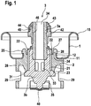
- Fig. 1 shows in section an embodiment of a solids valve according to the invention, inserted in a valve plate 1.
- the solids valve is clamped on the dome of the can via the valve plate 1, the valve plate with its crimped rim 15 engaging over and around the upper edge of the can dome.
- the valve disk 1 itself has a central recess around which a trough-shaped or trough-shaped central part 11 runs. On the inside, the valve disk 1 is delimited by the rising edge 12, while the tub rises to the Krimprand 15 on the outside.
- valve body 1 Inside the valve disk 1 is the valve body 2, in the central round recess of which the valve stem 3 is guided.
- the valve body 1 is fixed via a rising edge 24 with an outwardly protruding projection 25 on the rising inner edge 12 of the valve disk 1; an outwardly pointing round surface 26 nestles against the underside of the trough 11 of the valve disk 1.
- the shape of the valve body 1 is stabilized by the circumferential outer edge 26 on the can side.
- the valve body 2 has the necessary sealing means to ensure the tightness of the valve with respect to the valve disk 1 around the stem 3. These are possibly sealing lips which are arranged against the rounded area of the valve disk 1 in the transition from the tub 11 to the rising edge 12.
- On the can side i.e. on the side of the valve body 2 facing the can interior, there is at least one circumferential sealing lip 23 which runs essentially parallel to the course of the central recess 21 and acts against the foot 31 of the stem.
- the foot 31 serves as a sealing seat and is a concentric extension of the stem 3 with a slightly curved course. In the rest or closed position of the stem 3 shown here, the sealing lip 23 acts against the foot 31 and prevents the contents of the can from entering the inlet opening 33 of the stem.
- the stem In the central recess 21 of the valve body 2, the stem is guided, which has a central channel 34 which serves as an outlet channel for the can contents.
- the stem On the can side, the stem has at least one lateral opening 33 which serves as an inlet opening for the can contents. In the rest position shown, this inlet opening 33 is closed by the sealing effect of the lip 23 of the valve body 2 against the sealing seat 31 of the stem. When the stem is pressed in, the lip loses its sealing effect and the contents of the can can enter the channel 34 via the inlet opening 33 and exit.
- the stem has in its lower part 3b inlet openings 33 which are evenly distributed over the circumference.
- the stem 3 of the solids valve is divided into two parts, an upper part 3a and a lower part 3b.
- the upper part 3a encloses the larger part of the channel 34 and is connected to the valve body 2 via a membrane 22.
- the valve body 2 and the upper part 3a of the stem 3 are manufactured in one piece using the injection molding process and are preferably made of the same material.
- the lower part 3b of the stem cooperates with the sealing lip 23, which acts against the foot 31 of the lower part 3b.
- the upper part 3a comprises the outlet opening of the valve according to the invention and the lower part 3b the inlet openings 33 for the can contents.
- the membrane 22, which connects the upper part 3a of the stem to the valve body 2, is arranged concentrically around the stem and has a substantially step-shaped course along the outside of the lower part 3b of the stem.
- the membrane 22 is sufficiently elastic to absorb the movement of the stem 3 when the pressure cell is triggered.
- the step-shaped course gives a reserve area, which compensates for the elongation of the membrane when triggered by the displacement of the stem 3.
- a circumferential recess 27 in the valve body 2, which leaves a gap between the upper end 24 of the valve body 2 and the membrane 22, is also used for this purpose.
- the membrane 22 attaches to the inside of the valve body 2, follows the course of its inner wall in the area on the can side and then continues in steps to the outer wall of the upper part 3a of the stem.
- the lower part 3b of the stem has an extension 35 on the socket side, which serves as an abutment for the spring element 40. Only the central part of the spring element 40 is shown.
- the valve body In the part 26 projecting towards the can, the valve body has two recesses 29 which engage in the holding arms of the spring element.
- the upper part 3a and the lower part 3b of the stem are positively connected to one another.
- the upper part 3a of the stem has a circumferential bead 28 at its end on the can side, which protrudes precisely into a corresponding widening of the channel 34 in the area of the lower part 3b of the stem.
- the upper part 3a of the stem has a cuff which is used to seal off an application aid, such as a foaming gun.
- a sealing collar is preferably made of a thermoplastic elastomer which brings the required sealing properties with it.
- the upper part 3a of the stem is closed by a fixing ring 43 made of a relatively hard material, which protrudes into the receptacle of a foaming gun and transfers the pressure of the trigger to the stem. Sealing collar 42 and fixing ring 43 are firmly connected to one another.
- the fixing ring has an annular incision 44 into which a projection 45 of the sealing collar protrudes.
- the sealing collar 42 is also secured to a recess 46 in the upper part 3a of the stem.
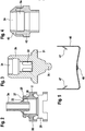
- Fig. 2 shows the combination of the upper part 3a of the stem and valve body 2.
- the upper part of the stem 3a is connected to the valve body 2 via the membrane 22, the membrane 22 taking a stepped profile.
- the stepped course guarantees the area reserve and at the same time the elasticity of the membrane and thus the flexible integration of the upper part 3a of the stem into the valve body.
- the externally protruding projection 25 of the valve body is used to fix it on the inner edge of the valve disk, the circumferential groove 27 providing the necessary elasticity for introducing the valve body 2 into the valve disk 1.
- the can-side extension 26 of the valve body 2 causes, on the one hand, a firm seat on the underside of the trough 11 of the valve disk 1 and, on the other hand, provides the recesses 29 for fixing the spring element 40.
- the socket-side part of the stem part 3a has a circumferential extension 28 which fits precisely into a corresponding extension of the channel 34 in the region of the lower part 3b of the stem, see Fig. 3 .
- the inlet openings 33 for the can contents when the valve is actuated and the foot 31, which acts as a sealing seat against the valve body 2, are shown.
- a socket-side extension 35 of the lower part 3b of the stem 3 interacts with the spring element 40 and at the same time serves to guide and support the valve 3.
- Fig. 4 shows the channel 34 of the stem with a sealing collar 42 arranged thereon for the connection of an application aid, for example a pistol.
- an application aid for example a pistol.
- the fixing ring 43 which is made of a hard material and absorbs the pressure of the deployment aid when the valve is actuated.
- Fig. 4 the sealing collar 42 and the fixing ring 43 are shown in section, while the upper part 3a of the stem is shown in plan view. It can be seen that the sealing collar 42 and fixing ring 43 are secured to one another in a type of toothing and the sealing collar 42 is secured to a recess of the stem part 3a. The cuff and the fixing ring are connected to one another in a kind of press fit.
- Fig. 5 shows the spring clip 40, which has two inwardly notched teeth 47 which are used to fix the spring clip 40 in the recesses 29 of the valve body 2.
- the teeth 47 cause a very elastic fit and snap into the recesses 29, they serve as holding arms of the spring clip.
- the spring clip 40 has a dent 48 in its central lower region, which protrudes towards the inside of the can.
- the dent 48 lies close to the extension 35 of the lower part 3b of the stem and takes up the pressure which is exerted on the stem by the deployment aid.
- the spring clip 40 bends under the pressure towards the can and causes the stem to be returned to the closed position after completion of the application process.
Landscapes
- Chemical & Material Sciences (AREA)
- Dispersion Chemistry (AREA)
- Engineering & Computer Science (AREA)
- Mechanical Engineering (AREA)
- Containers And Packaging Bodies Having A Special Means To Remove Contents (AREA)
- Nozzles (AREA)
- Closures For Containers (AREA)
Claims (12)
- Soupape en matière solide pour des boîtes pressurisées, en particulier pour la distribution de mousses de montage, avec une tête de soupape (1), un corps de soupape (2) disposé dans la tête de soupape (1), une tige (3) montée dans un évidement central (21) du corps de soupape (2), avec au moins une ouverture d'entrée (33) pouvant être dégagée par l'actionnement de la tige (3) pour le contenu de boîte pressurisée, au moins une ouverture de sortie, un canal (34) reliant l'ouverture d'entrée (33) à l'ouverture de sortie, au moins un élément d'étanchéité (23) agissant entre le corps de soupape (2) et la tige (3), ainsi qu'un élément de ressort (40), caractérisée en ce que la tige (3) est réalisée en deux parties, dans lequel une partie supérieure (3a) est reliée par complémentarité de forme ou à force à une partie inférieure (3b), une membrane élastique (22) périphérique relie de manière intégrale le corps de soupape (2) à la partie supérieure (3a) de la tige (3) et les deux parties (3a, 3b) de la tige (3) forment une unité fonctionnelle, laquelle reçoit le canal (34).
- Soupape en matière solide selon la revendication 1, caractérisée en ce que la membrane élastique (22) est réalisée de manière étagée et s'étend autour du bord, côté soupape, de la partie inférieure (3b) de la tige (3).
- Soupape en matière solide selon la revendication 1 ou 2, caractérisée en ce qu'un renfoncement (27) périphérique est disposé entre le bord supérieur du corps de soupape (2) et la membrane élastique (22).
- Soupape en matière solide selon l'une quelconque des revendications précédentes, caractérisée en ce que la membrane flexible (22) présente une réserve de surface pour compenser un allongement apparaissant lors de l'actionnement de la tige (3).
- Soupape en matière solide selon l'une quelconque des revendications précédentes, caractérisée en ce que le logement central de la partie inférieure (3b) présente un élargissement périphérique côté intérieur, avec lequel un bourrelet (28) périphérique côté extérieur de la partie supérieure (3a) de la tige (3) vient en prise par complémentarité de forme.
- Soupape en matière solide selon l'une quelconque des revendications précédentes, caractérisée en ce que le corps de soupape (2) présente une lèvre d'étanchéité (23) périphérique du côté de la boîte, qui coopère avec une partie faisant saillie (3) périphérique de la partie inférieure (3b) de la tige.
- Soupape en matière solide selon l'une quelconque des revendications précédentes, caractérisée en ce que le corps de soupape présente côté boîte un prolongement (26), qui entoure la partie inférieure de la tige (3) et fait office d'élément de maintien pour l'élément de ressort (40).
- Soupape en matière solide selon la revendication 7, caractérisée en ce que l'élément de ressort (40) est un étrier de ressort avec deux bras, dont les bras sont fixés dans des évidements (29) sur le corps de soupape (2).
- Soupape en matière solide selon la revendication 8, caractérisée en ce que l'étrier de ressort est cintré vers l'intérieur et présente un bombement convexe de manière centrale, dans lequel une partie faisant saillie centrale (35) de la partie inférieure (3b) de la tige (3) dépasse et qui sert au centrage de la tige (3).
- Soupape en matière solide selon la revendication 8 ou 9, caractérisée en ce que les bras de l'élément de ressort (40) présentent des encoches côté boîte, qui viennent en prise avec l'évidement du corps de soupape.
- Soupape en matière solide selon l'une quelconque des revendications précédentes, caractérisée par un manchon d'étanchéité (42), qui entoure la partie supérieure (3a) de la tige (3).
- Soupape en matière solide selon la revendication 11, caractérisée en ce que la partie supérieure (3a) de la tige (3) se termine en une bague de blocage (43), dans laquelle la bague de blocage (43) présente côté boîte une rainure (44) périphérique, avec laquelle une saillie (45) périphérique du manchon d'étanchéité (42) vient en prise par complémentarité de forme.
Priority Applications (1)
| Application Number | Priority Date | Filing Date | Title |
|---|---|---|---|
| PL18765560T PL3668802T3 (pl) | 2017-08-16 | 2018-08-16 | Zawór do substancji stałych dla puszek ciśnieniowych |
Applications Claiming Priority (2)
| Application Number | Priority Date | Filing Date | Title |
|---|---|---|---|
| DE102017118704.9A DE102017118704A1 (de) | 2017-08-16 | 2017-08-16 | Feststoffventile für Druckdosen |
| PCT/EP2018/072224 WO2019034733A1 (fr) | 2017-08-16 | 2018-08-16 | Soupapes pour matériaux solides pour récipients sous pression |
Publications (2)
| Publication Number | Publication Date |
|---|---|
| EP3668802A1 EP3668802A1 (fr) | 2020-06-24 |
| EP3668802B1 true EP3668802B1 (fr) | 2021-09-29 |
Family
ID=63517833
Family Applications (1)
| Application Number | Title | Priority Date | Filing Date |
|---|---|---|---|
| EP18765560.0A Active EP3668802B1 (fr) | 2017-08-16 | 2018-08-16 | Soupape en matériaux solides pour récipients sous pression |
Country Status (6)
| Country | Link |
|---|---|
| US (1) | US11214432B2 (fr) |
| EP (1) | EP3668802B1 (fr) |
| DE (1) | DE102017118704A1 (fr) |
| PL (1) | PL3668802T3 (fr) |
| RU (1) | RU2768415C2 (fr) |
| WO (1) | WO2019034733A1 (fr) |
Family Cites Families (42)
| Publication number | Priority date | Publication date | Assignee | Title |
|---|---|---|---|---|
| BE563333A (fr) * | 1957-01-08 | |||
| FR1255997A (fr) * | 1960-02-01 | 1961-03-17 | Rhone Poulenc Sa | Valve pour récipients atomiseurs |
| NL262110A (fr) * | 1960-03-18 | |||
| US3079048A (en) * | 1960-09-07 | 1963-02-26 | Wolfson | Non-drip valves for pressurized containers |
| FR1298425A (fr) * | 1961-05-30 | 1962-07-13 | Anciens Etablissements E Rober | Perfectionnements aux appareils distributeurs de doses de produits déterminées volumétriquement |
| US3201081A (en) * | 1961-08-14 | 1965-08-17 | John K Lyon | Dispensing valve having cup-like deformable sealing element |
| US3159318A (en) * | 1962-03-20 | 1964-12-01 | Edward H Green | Aerosol valve housing construction and method of making same |
| US3254676A (en) * | 1962-11-15 | 1966-06-07 | Risdon Mfg Co | Tiltable, sequentially operated valves for pressurized package |
| US3195787A (en) * | 1962-11-24 | 1965-07-20 | Kitabayashi Seiichi | Aerosol dispenser |
| US3146922A (en) * | 1963-01-15 | 1964-09-01 | Risdon Mfg Co | Sealing device for pressurized package |
| NL137619C (fr) * | 1963-07-31 | |||
| US3231150A (en) * | 1964-02-26 | 1966-01-25 | Seary Ltd | Metering button cap for pressurized container valves |
| US3269615A (en) * | 1964-05-27 | 1966-08-30 | Jr Royal T Ferry | Aerosol container with metering valve |
| US3375957A (en) * | 1966-06-08 | 1968-04-02 | Aerosol Res Company | Pressure fillable aerosol valve assembly |
| US3434695A (en) * | 1967-05-03 | 1969-03-25 | Scovill Manufacturing Co | Valve structure for aerosol container |
| US3508689A (en) * | 1967-10-10 | 1970-04-28 | Gillette Co | Valve for pressurized container |
| US3434633A (en) * | 1967-10-23 | 1969-03-25 | Scovill Manufacturing Co | Dispensing actuator for aerosol containers |
| GB1287735A (en) * | 1968-10-21 | 1972-09-06 | Richard Terenc Macguire-Cooper | Valves for pressurized dispensing containers |
| US3777946A (en) * | 1972-05-03 | 1973-12-11 | Warner Lambert Co | Aerosol metering button |
| ZA735711B (en) * | 1972-08-25 | 1975-04-30 | Macguire Cooper | Pressurised containers |
| GB1446858A (en) * | 1972-08-25 | 1976-08-18 | Macguire Cooper | Pressurized packaging |
| US3990613A (en) * | 1975-06-30 | 1976-11-09 | Chill-Can International, Ltd. | Aerosol container closure |
| DE2745445A1 (de) * | 1977-10-08 | 1979-04-12 | Fritz Albert Riegler Kg Kunsts | Ventilanordnung fuer druckbehaelter |
| US4522318A (en) * | 1980-12-19 | 1985-06-11 | Luigi Del Bon | Discharge valve for use in a pressurized container |
| US4671436A (en) * | 1984-07-31 | 1987-06-09 | Mckesson Corporation | Syphon assembly and package incorporating the assembly |
| US5027985A (en) * | 1986-12-03 | 1991-07-02 | Abplanalp Robert H | Aerosol valve |
| FR2612889B1 (fr) * | 1987-03-25 | 1989-07-21 | Promotion Rech Innovation Tec | Tete de dosage pour recipients sous pression a valve continue |
| US4887743A (en) * | 1987-06-10 | 1989-12-19 | Blake William S | Aerosol valve |
| US4852807A (en) * | 1988-03-28 | 1989-08-01 | Stoody William R | Neoteric simplified aerosol valve |
| CH676354A5 (fr) * | 1988-07-14 | 1991-01-15 | Ehrensperger C Ag | |
| FR2639259B1 (fr) * | 1988-11-21 | 1991-03-29 | Oreal | Embout pour distribuer un produit, en particulier un produit moussant |
| US4991751A (en) * | 1989-12-19 | 1991-02-12 | Precision Valve Corporation | Foam actuator for metering an aerosol product |
| DE4426730C2 (de) * | 1994-07-28 | 2002-09-26 | Ehrensperger C Ag | Ventileinsatz für unter Druck stehende Fluidbehälter |
| DE4443287C2 (de) * | 1994-12-06 | 2001-08-09 | Amv Autom Montage Vertrieb Fa | Ventilanordnung für einen Behälter zur Abgabe von unter Druck stehender Flüssigkeit oder Schaum |
| DE19710541A1 (de) * | 1997-03-14 | 1998-09-17 | Ehrensperger C Ag | Als Ventileinsatz für unter Druck stehende Fluidbehälter dienende Vorrichtung |
| FR2786167B1 (fr) * | 1998-11-23 | 2001-01-05 | Oreal | Valve pour la distribution d'un liquide sous pression, recipient equipe de cette valve et procede de conditionnement d'un recipient ainsi equipe |
| GB0315791D0 (en) * | 2003-07-07 | 2003-08-13 | 3M Innovative Properties Co | Two component molded valve stems |
| DE102004060491A1 (de) * | 2004-12-16 | 2006-06-29 | Wella Ag | Kappe für einen Aerosolbehälter oder einen Sprühbehälter |
| DE102007040296A1 (de) * | 2007-08-24 | 2009-02-26 | Fazekas, Gàbor | Feststoffventil |
| DE102008019224B4 (de) * | 2008-04-17 | 2010-09-02 | Lindal Dispenser Gmbh | Ventilanordnung für einen unter Druck stehenden Fluidbehälter |
| DE102008051888B4 (de) * | 2008-10-16 | 2011-02-03 | C. Ehrensperger Ag | Ventil für einen Behälter zur Abgabe von unter Druck stehendem Fluid |
| JP7311527B2 (ja) * | 2018-04-10 | 2023-07-19 | ディディピー スペシャルティ エレクトロニック マテリアルズ ユーエス,エルエルシー | ディスペンサアダプタ |
-
2017
- 2017-08-16 DE DE102017118704.9A patent/DE102017118704A1/de not_active Withdrawn
-
2018
- 2018-08-16 RU RU2020110520A patent/RU2768415C2/ru active
- 2018-08-16 WO PCT/EP2018/072224 patent/WO2019034733A1/fr unknown
- 2018-08-16 US US16/636,593 patent/US11214432B2/en active Active
- 2018-08-16 PL PL18765560T patent/PL3668802T3/pl unknown
- 2018-08-16 EP EP18765560.0A patent/EP3668802B1/fr active Active
Also Published As
| Publication number | Publication date |
|---|---|
| WO2019034733A1 (fr) | 2019-02-21 |
| DE102017118704A1 (de) | 2019-02-21 |
| EP3668802A1 (fr) | 2020-06-24 |
| US11214432B2 (en) | 2022-01-04 |
| PL3668802T3 (pl) | 2022-01-31 |
| RU2020110520A (ru) | 2021-09-16 |
| US20200369457A1 (en) | 2020-11-26 |
| RU2020110520A3 (fr) | 2021-09-16 |
| RU2768415C2 (ru) | 2022-03-24 |
Similar Documents
| Publication | Publication Date | Title |
|---|---|---|
| EP2028131B1 (fr) | Soupape en matière solide | |
| EP1485309B1 (fr) | Soupape | |
| EP2131962B1 (fr) | Dispositif distributeur | |
| DE102009030627B4 (de) | Ventil und Abgabevorrichtung | |
| EP1737759B2 (fr) | Dispositif pour faire sortir un liquide de l'enceinte d'un recipient | |
| EP3044123B1 (fr) | Soupape pour matière solide | |
| EP2481484A1 (fr) | Dispositif de dépôt | |
| EP1842798B1 (fr) | Soupape de dosage et dispositif destiné à la livraison d'un liquide cosmétique de préférence | |
| DE4443287A1 (de) | Ventilanordnung für einen Behälter zur Abgabe von unter Druck stehender Flüssigkeit oder Schaum | |
| EP1373094B1 (fr) | Recipient sous pression permettant de melanger et de distribuer des materiaux a deux composants | |
| EP1313652A2 (fr) | Bombe a aerosol | |
| EP3484628B1 (fr) | Distributeur de produits liquides ou pâteux | |
| DE2136220C3 (de) | Ventileinrichtung zum Be- und Entlüften eines Produktbehälters | |
| EP1912002B1 (fr) | Soupape de purge d'air pour le réservoir de carburant d'un véhicule automobile | |
| WO2007107174A1 (fr) | Module de soupape de distribution pour distribuer des liquides sous pression et recipient contenant un tel module | |
| WO1989008062A1 (fr) | Recipient aerosol | |
| EP3668802B1 (fr) | Soupape en matériaux solides pour récipients sous pression | |
| WO2005113383A1 (fr) | Aerosol comprenant une enveloppe interne | |
| EP3433493B1 (fr) | Pompe de dosage pour un appareil de dosage, ainsi qu'un appareil de dosage | |
| DE102005049531A1 (de) | Spender für flüssige oder pastöse Massen | |
| DE2612052A1 (de) | Ventil fuer eine vorrichtung zur dosierten abgabe von stoffen | |
| DE4321568C1 (de) | Verschließbarer Behälter zur Abgabe von viskosen Stoffen | |
| WO2017186233A1 (fr) | Fermeture de bouteille pour boisson | |
| DE102009022215B4 (de) | Ventil zur dosierten Abgabe von Flüssigkeiten | |
| DE102018105321A1 (de) | Verschlussvorrichtung für einen Behälter |
Legal Events
| Date | Code | Title | Description |
|---|---|---|---|
| STAA | Information on the status of an ep patent application or granted ep patent |
Free format text: STATUS: UNKNOWN |
|
| STAA | Information on the status of an ep patent application or granted ep patent |
Free format text: STATUS: THE INTERNATIONAL PUBLICATION HAS BEEN MADE |
|
| PUAI | Public reference made under article 153(3) epc to a published international application that has entered the european phase |
Free format text: ORIGINAL CODE: 0009012 |
|
| STAA | Information on the status of an ep patent application or granted ep patent |
Free format text: STATUS: REQUEST FOR EXAMINATION WAS MADE |
|
| 17P | Request for examination filed |
Effective date: 20200316 |
|
| AK | Designated contracting states |
Kind code of ref document: A1 Designated state(s): AL AT BE BG CH CY CZ DE DK EE ES FI FR GB GR HR HU IE IS IT LI LT LU LV MC MK MT NL NO PL PT RO RS SE SI SK SM TR |
|
| AX | Request for extension of the european patent |
Extension state: BA ME |
|
| DAV | Request for validation of the european patent (deleted) | ||
| DAX | Request for extension of the european patent (deleted) | ||
| GRAP | Despatch of communication of intention to grant a patent |
Free format text: ORIGINAL CODE: EPIDOSNIGR1 |
|
| STAA | Information on the status of an ep patent application or granted ep patent |
Free format text: STATUS: GRANT OF PATENT IS INTENDED |
|
| RIC1 | Information provided on ipc code assigned before grant |
Ipc: B65D 83/38 20060101ALN20210311BHEP Ipc: B65D 83/48 20060101AFI20210311BHEP |
|
| RIC1 | Information provided on ipc code assigned before grant |
Ipc: B65D 83/38 20060101ALN20210312BHEP Ipc: B65D 83/48 20060101AFI20210312BHEP |
|
| INTG | Intention to grant announced |
Effective date: 20210413 |
|
| RIC1 | Information provided on ipc code assigned before grant |
Ipc: B65D 83/38 20060101ALN20210401BHEP Ipc: B65D 83/48 20060101AFI20210401BHEP |
|
| GRAS | Grant fee paid |
Free format text: ORIGINAL CODE: EPIDOSNIGR3 |
|
| GRAA | (expected) grant |
Free format text: ORIGINAL CODE: 0009210 |
|
| STAA | Information on the status of an ep patent application or granted ep patent |
Free format text: STATUS: THE PATENT HAS BEEN GRANTED |
|
| AK | Designated contracting states |
Kind code of ref document: B1 Designated state(s): AL AT BE BG CH CY CZ DE DK EE ES FI FR GB GR HR HU IE IS IT LI LT LU LV MC MK MT NL NO PL PT RO RS SE SI SK SM TR |
|
| REG | Reference to a national code |
Ref country code: GB Ref legal event code: FG4D Free format text: NOT ENGLISH |
|
| REG | Reference to a national code |
Ref country code: DE Ref legal event code: R096 Ref document number: 502018007305 Country of ref document: DE |
|
| REG | Reference to a national code |
Ref country code: CH Ref legal event code: EP Ref country code: AT Ref legal event code: REF Ref document number: 1434014 Country of ref document: AT Kind code of ref document: T Effective date: 20211015 |
|
| REG | Reference to a national code |
Ref country code: IE Ref legal event code: FG4D Free format text: LANGUAGE OF EP DOCUMENT: GERMAN |
|
| RAP4 | Party data changed (patent owner data changed or rights of a patent transferred) |
Owner name: FAZEKAS, GABOR |
|
| REG | Reference to a national code |
Ref country code: LT Ref legal event code: MG9D |
|
| PG25 | Lapsed in a contracting state [announced via postgrant information from national office to epo] |
Ref country code: FI Free format text: LAPSE BECAUSE OF FAILURE TO SUBMIT A TRANSLATION OF THE DESCRIPTION OR TO PAY THE FEE WITHIN THE PRESCRIBED TIME-LIMIT Effective date: 20210929 Ref country code: HR Free format text: LAPSE BECAUSE OF FAILURE TO SUBMIT A TRANSLATION OF THE DESCRIPTION OR TO PAY THE FEE WITHIN THE PRESCRIBED TIME-LIMIT Effective date: 20210929 Ref country code: RS Free format text: LAPSE BECAUSE OF FAILURE TO SUBMIT A TRANSLATION OF THE DESCRIPTION OR TO PAY THE FEE WITHIN THE PRESCRIBED TIME-LIMIT Effective date: 20210929 Ref country code: SE Free format text: LAPSE BECAUSE OF FAILURE TO SUBMIT A TRANSLATION OF THE DESCRIPTION OR TO PAY THE FEE WITHIN THE PRESCRIBED TIME-LIMIT Effective date: 20210929 Ref country code: LT Free format text: LAPSE BECAUSE OF FAILURE TO SUBMIT A TRANSLATION OF THE DESCRIPTION OR TO PAY THE FEE WITHIN THE PRESCRIBED TIME-LIMIT Effective date: 20210929 Ref country code: BG Free format text: LAPSE BECAUSE OF FAILURE TO SUBMIT A TRANSLATION OF THE DESCRIPTION OR TO PAY THE FEE WITHIN THE PRESCRIBED TIME-LIMIT Effective date: 20211229 Ref country code: NO Free format text: LAPSE BECAUSE OF FAILURE TO SUBMIT A TRANSLATION OF THE DESCRIPTION OR TO PAY THE FEE WITHIN THE PRESCRIBED TIME-LIMIT Effective date: 20211229 |
|
| REG | Reference to a national code |
Ref country code: NL Ref legal event code: MP Effective date: 20210929 |
|
| REG | Reference to a national code |
Ref country code: EE Ref legal event code: FG4A Ref document number: E021774 Country of ref document: EE Effective date: 20211229 |
|
| PG25 | Lapsed in a contracting state [announced via postgrant information from national office to epo] |
Ref country code: LV Free format text: LAPSE BECAUSE OF FAILURE TO SUBMIT A TRANSLATION OF THE DESCRIPTION OR TO PAY THE FEE WITHIN THE PRESCRIBED TIME-LIMIT Effective date: 20210929 Ref country code: GR Free format text: LAPSE BECAUSE OF FAILURE TO SUBMIT A TRANSLATION OF THE DESCRIPTION OR TO PAY THE FEE WITHIN THE PRESCRIBED TIME-LIMIT Effective date: 20211230 |
|
| PG25 | Lapsed in a contracting state [announced via postgrant information from national office to epo] |
Ref country code: IS Free format text: LAPSE BECAUSE OF FAILURE TO SUBMIT A TRANSLATION OF THE DESCRIPTION OR TO PAY THE FEE WITHIN THE PRESCRIBED TIME-LIMIT Effective date: 20220129 Ref country code: SK Free format text: LAPSE BECAUSE OF FAILURE TO SUBMIT A TRANSLATION OF THE DESCRIPTION OR TO PAY THE FEE WITHIN THE PRESCRIBED TIME-LIMIT Effective date: 20210929 Ref country code: RO Free format text: LAPSE BECAUSE OF FAILURE TO SUBMIT A TRANSLATION OF THE DESCRIPTION OR TO PAY THE FEE WITHIN THE PRESCRIBED TIME-LIMIT Effective date: 20210929 Ref country code: PT Free format text: LAPSE BECAUSE OF FAILURE TO SUBMIT A TRANSLATION OF THE DESCRIPTION OR TO PAY THE FEE WITHIN THE PRESCRIBED TIME-LIMIT Effective date: 20220131 Ref country code: NL Free format text: LAPSE BECAUSE OF FAILURE TO SUBMIT A TRANSLATION OF THE DESCRIPTION OR TO PAY THE FEE WITHIN THE PRESCRIBED TIME-LIMIT Effective date: 20210929 Ref country code: ES Free format text: LAPSE BECAUSE OF FAILURE TO SUBMIT A TRANSLATION OF THE DESCRIPTION OR TO PAY THE FEE WITHIN THE PRESCRIBED TIME-LIMIT Effective date: 20210929 Ref country code: CZ Free format text: LAPSE BECAUSE OF FAILURE TO SUBMIT A TRANSLATION OF THE DESCRIPTION OR TO PAY THE FEE WITHIN THE PRESCRIBED TIME-LIMIT Effective date: 20210929 Ref country code: AL Free format text: LAPSE BECAUSE OF FAILURE TO SUBMIT A TRANSLATION OF THE DESCRIPTION OR TO PAY THE FEE WITHIN THE PRESCRIBED TIME-LIMIT Effective date: 20210929 |
|
| REG | Reference to a national code |
Ref country code: DE Ref legal event code: R097 Ref document number: 502018007305 Country of ref document: DE |
|
| PG25 | Lapsed in a contracting state [announced via postgrant information from national office to epo] |
Ref country code: DK Free format text: LAPSE BECAUSE OF FAILURE TO SUBMIT A TRANSLATION OF THE DESCRIPTION OR TO PAY THE FEE WITHIN THE PRESCRIBED TIME-LIMIT Effective date: 20210929 |
|
| PLBE | No opposition filed within time limit |
Free format text: ORIGINAL CODE: 0009261 |
|
| STAA | Information on the status of an ep patent application or granted ep patent |
Free format text: STATUS: NO OPPOSITION FILED WITHIN TIME LIMIT |
|
| 26N | No opposition filed |
Effective date: 20220630 |
|
| PG25 | Lapsed in a contracting state [announced via postgrant information from national office to epo] |
Ref country code: SI Free format text: LAPSE BECAUSE OF FAILURE TO SUBMIT A TRANSLATION OF THE DESCRIPTION OR TO PAY THE FEE WITHIN THE PRESCRIBED TIME-LIMIT Effective date: 20210929 |
|
| PG25 | Lapsed in a contracting state [announced via postgrant information from national office to epo] |
Ref country code: IT Free format text: LAPSE BECAUSE OF FAILURE TO SUBMIT A TRANSLATION OF THE DESCRIPTION OR TO PAY THE FEE WITHIN THE PRESCRIBED TIME-LIMIT Effective date: 20210929 |
|
| PG25 | Lapsed in a contracting state [announced via postgrant information from national office to epo] |
Ref country code: MC Free format text: LAPSE BECAUSE OF FAILURE TO SUBMIT A TRANSLATION OF THE DESCRIPTION OR TO PAY THE FEE WITHIN THE PRESCRIBED TIME-LIMIT Effective date: 20210929 |
|
| GBPC | Gb: european patent ceased through non-payment of renewal fee |
Effective date: 20220816 |
|
| PG25 | Lapsed in a contracting state [announced via postgrant information from national office to epo] |
Ref country code: LU Free format text: LAPSE BECAUSE OF NON-PAYMENT OF DUE FEES Effective date: 20220816 |
|
| P01 | Opt-out of the competence of the unified patent court (upc) registered |
Effective date: 20230428 |
|
| PG25 | Lapsed in a contracting state [announced via postgrant information from national office to epo] |
Ref country code: IE Free format text: LAPSE BECAUSE OF NON-PAYMENT OF DUE FEES Effective date: 20220816 Ref country code: FR Free format text: LAPSE BECAUSE OF NON-PAYMENT OF DUE FEES Effective date: 20220831 |
|
| PG25 | Lapsed in a contracting state [announced via postgrant information from national office to epo] |
Ref country code: GB Free format text: LAPSE BECAUSE OF NON-PAYMENT OF DUE FEES Effective date: 20220816 |
|
| PGFP | Annual fee paid to national office [announced via postgrant information from national office to epo] |
Ref country code: EE Payment date: 20230814 Year of fee payment: 6 Ref country code: CH Payment date: 20230902 Year of fee payment: 6 |
|
| PGFP | Annual fee paid to national office [announced via postgrant information from national office to epo] |
Ref country code: PL Payment date: 20230803 Year of fee payment: 6 Ref country code: DE Payment date: 20230821 Year of fee payment: 6 Ref country code: BE Payment date: 20230821 Year of fee payment: 6 |
|
| PG25 | Lapsed in a contracting state [announced via postgrant information from national office to epo] |
Ref country code: SM Free format text: LAPSE BECAUSE OF FAILURE TO SUBMIT A TRANSLATION OF THE DESCRIPTION OR TO PAY THE FEE WITHIN THE PRESCRIBED TIME-LIMIT Effective date: 20210929 Ref country code: CY Free format text: LAPSE BECAUSE OF FAILURE TO SUBMIT A TRANSLATION OF THE DESCRIPTION OR TO PAY THE FEE WITHIN THE PRESCRIBED TIME-LIMIT Effective date: 20210929 |