EP3668765B1 - Systems and methods for redundant wheel speed sensing - Google Patents
Systems and methods for redundant wheel speed sensing Download PDFInfo
- Publication number
- EP3668765B1 EP3668765B1 EP18750404.8A EP18750404A EP3668765B1 EP 3668765 B1 EP3668765 B1 EP 3668765B1 EP 18750404 A EP18750404 A EP 18750404A EP 3668765 B1 EP3668765 B1 EP 3668765B1
- Authority
- EP
- European Patent Office
- Prior art keywords
- wheel speed
- control unit
- electronic control
- speed sensor
- ecu
- Prior art date
- Legal status (The legal status is an assumption and is not a legal conclusion. Google has not performed a legal analysis and makes no representation as to the accuracy of the status listed.)
- Active
Links
- 238000000034 method Methods 0.000 title claims description 13
- 238000012544 monitoring process Methods 0.000 claims description 55
- 238000004891 communication Methods 0.000 claims description 16
- 238000012360 testing method Methods 0.000 claims description 7
- 238000012545 processing Methods 0.000 claims description 4
- 230000001360 synchronised effect Effects 0.000 claims description 4
- 238000013500 data storage Methods 0.000 description 2
- 230000007257 malfunction Effects 0.000 description 2
- 239000004065 semiconductor Substances 0.000 description 2
- 230000003044 adaptive effect Effects 0.000 description 1
- 238000004364 calculation method Methods 0.000 description 1
- 238000010276 construction Methods 0.000 description 1
- 238000010586 diagram Methods 0.000 description 1
- 230000003287 optical effect Effects 0.000 description 1
- 238000010200 validation analysis Methods 0.000 description 1
Images


Classifications
-
- B—PERFORMING OPERATIONS; TRANSPORTING
- B60—VEHICLES IN GENERAL
- B60T—VEHICLE BRAKE CONTROL SYSTEMS OR PARTS THEREOF; BRAKE CONTROL SYSTEMS OR PARTS THEREOF, IN GENERAL; ARRANGEMENT OF BRAKING ELEMENTS ON VEHICLES IN GENERAL; PORTABLE DEVICES FOR PREVENTING UNWANTED MOVEMENT OF VEHICLES; VEHICLE MODIFICATIONS TO FACILITATE COOLING OF BRAKES
- B60T8/00—Arrangements for adjusting wheel-braking force to meet varying vehicular or ground-surface conditions, e.g. limiting or varying distribution of braking force
- B60T8/32—Arrangements for adjusting wheel-braking force to meet varying vehicular or ground-surface conditions, e.g. limiting or varying distribution of braking force responsive to a speed condition, e.g. acceleration or deceleration
- B60T8/88—Arrangements for adjusting wheel-braking force to meet varying vehicular or ground-surface conditions, e.g. limiting or varying distribution of braking force responsive to a speed condition, e.g. acceleration or deceleration with failure responsive means, i.e. means for detecting and indicating faulty operation of the speed responsive control means
- B60T8/885—Arrangements for adjusting wheel-braking force to meet varying vehicular or ground-surface conditions, e.g. limiting or varying distribution of braking force responsive to a speed condition, e.g. acceleration or deceleration with failure responsive means, i.e. means for detecting and indicating faulty operation of the speed responsive control means using electrical circuitry
-
- B—PERFORMING OPERATIONS; TRANSPORTING
- B60—VEHICLES IN GENERAL
- B60T—VEHICLE BRAKE CONTROL SYSTEMS OR PARTS THEREOF; BRAKE CONTROL SYSTEMS OR PARTS THEREOF, IN GENERAL; ARRANGEMENT OF BRAKING ELEMENTS ON VEHICLES IN GENERAL; PORTABLE DEVICES FOR PREVENTING UNWANTED MOVEMENT OF VEHICLES; VEHICLE MODIFICATIONS TO FACILITATE COOLING OF BRAKES
- B60T13/00—Transmitting braking action from initiating means to ultimate brake actuator with power assistance or drive; Brake systems incorporating such transmitting means, e.g. air-pressure brake systems
- B60T13/10—Transmitting braking action from initiating means to ultimate brake actuator with power assistance or drive; Brake systems incorporating such transmitting means, e.g. air-pressure brake systems with fluid assistance, drive, or release
- B60T13/66—Electrical control in fluid-pressure brake systems
- B60T13/662—Electrical control in fluid-pressure brake systems characterised by specified functions of the control system components
-
- B—PERFORMING OPERATIONS; TRANSPORTING
- B60—VEHICLES IN GENERAL
- B60T—VEHICLE BRAKE CONTROL SYSTEMS OR PARTS THEREOF; BRAKE CONTROL SYSTEMS OR PARTS THEREOF, IN GENERAL; ARRANGEMENT OF BRAKING ELEMENTS ON VEHICLES IN GENERAL; PORTABLE DEVICES FOR PREVENTING UNWANTED MOVEMENT OF VEHICLES; VEHICLE MODIFICATIONS TO FACILITATE COOLING OF BRAKES
- B60T17/00—Component parts, details, or accessories of power brake systems not covered by groups B60T8/00, B60T13/00 or B60T15/00, or presenting other characteristic features
- B60T17/18—Safety devices; Monitoring
- B60T17/22—Devices for monitoring or checking brake systems; Signal devices
- B60T17/221—Procedure or apparatus for checking or keeping in a correct functioning condition of brake systems
-
- B—PERFORMING OPERATIONS; TRANSPORTING
- B60—VEHICLES IN GENERAL
- B60T—VEHICLE BRAKE CONTROL SYSTEMS OR PARTS THEREOF; BRAKE CONTROL SYSTEMS OR PARTS THEREOF, IN GENERAL; ARRANGEMENT OF BRAKING ELEMENTS ON VEHICLES IN GENERAL; PORTABLE DEVICES FOR PREVENTING UNWANTED MOVEMENT OF VEHICLES; VEHICLE MODIFICATIONS TO FACILITATE COOLING OF BRAKES
- B60T7/00—Brake-action initiating means
- B60T7/12—Brake-action initiating means for automatic initiation; for initiation not subject to will of driver or passenger
- B60T7/22—Brake-action initiating means for automatic initiation; for initiation not subject to will of driver or passenger initiated by contact of vehicle, e.g. bumper, with an external object, e.g. another vehicle, or by means of contactless obstacle detectors mounted on the vehicle
-
- B—PERFORMING OPERATIONS; TRANSPORTING
- B60—VEHICLES IN GENERAL
- B60T—VEHICLE BRAKE CONTROL SYSTEMS OR PARTS THEREOF; BRAKE CONTROL SYSTEMS OR PARTS THEREOF, IN GENERAL; ARRANGEMENT OF BRAKING ELEMENTS ON VEHICLES IN GENERAL; PORTABLE DEVICES FOR PREVENTING UNWANTED MOVEMENT OF VEHICLES; VEHICLE MODIFICATIONS TO FACILITATE COOLING OF BRAKES
- B60T8/00—Arrangements for adjusting wheel-braking force to meet varying vehicular or ground-surface conditions, e.g. limiting or varying distribution of braking force
- B60T8/17—Using electrical or electronic regulation means to control braking
-
- B—PERFORMING OPERATIONS; TRANSPORTING
- B60—VEHICLES IN GENERAL
- B60T—VEHICLE BRAKE CONTROL SYSTEMS OR PARTS THEREOF; BRAKE CONTROL SYSTEMS OR PARTS THEREOF, IN GENERAL; ARRANGEMENT OF BRAKING ELEMENTS ON VEHICLES IN GENERAL; PORTABLE DEVICES FOR PREVENTING UNWANTED MOVEMENT OF VEHICLES; VEHICLE MODIFICATIONS TO FACILITATE COOLING OF BRAKES
- B60T8/00—Arrangements for adjusting wheel-braking force to meet varying vehicular or ground-surface conditions, e.g. limiting or varying distribution of braking force
- B60T8/32—Arrangements for adjusting wheel-braking force to meet varying vehicular or ground-surface conditions, e.g. limiting or varying distribution of braking force responsive to a speed condition, e.g. acceleration or deceleration
- B60T8/72—Arrangements for adjusting wheel-braking force to meet varying vehicular or ground-surface conditions, e.g. limiting or varying distribution of braking force responsive to a speed condition, e.g. acceleration or deceleration responsive to a difference between a speed condition, e.g. deceleration, and a fixed reference
- B60T8/76—Arrangements for adjusting wheel-braking force to meet varying vehicular or ground-surface conditions, e.g. limiting or varying distribution of braking force responsive to a speed condition, e.g. acceleration or deceleration responsive to a difference between a speed condition, e.g. deceleration, and a fixed reference two or more sensing means from different wheels indicative of the same type of speed condition
-
- B—PERFORMING OPERATIONS; TRANSPORTING
- B60—VEHICLES IN GENERAL
- B60T—VEHICLE BRAKE CONTROL SYSTEMS OR PARTS THEREOF; BRAKE CONTROL SYSTEMS OR PARTS THEREOF, IN GENERAL; ARRANGEMENT OF BRAKING ELEMENTS ON VEHICLES IN GENERAL; PORTABLE DEVICES FOR PREVENTING UNWANTED MOVEMENT OF VEHICLES; VEHICLE MODIFICATIONS TO FACILITATE COOLING OF BRAKES
- B60T13/00—Transmitting braking action from initiating means to ultimate brake actuator with power assistance or drive; Brake systems incorporating such transmitting means, e.g. air-pressure brake systems
- B60T13/74—Transmitting braking action from initiating means to ultimate brake actuator with power assistance or drive; Brake systems incorporating such transmitting means, e.g. air-pressure brake systems with electrical assistance or drive
-
- B—PERFORMING OPERATIONS; TRANSPORTING
- B60—VEHICLES IN GENERAL
- B60T—VEHICLE BRAKE CONTROL SYSTEMS OR PARTS THEREOF; BRAKE CONTROL SYSTEMS OR PARTS THEREOF, IN GENERAL; ARRANGEMENT OF BRAKING ELEMENTS ON VEHICLES IN GENERAL; PORTABLE DEVICES FOR PREVENTING UNWANTED MOVEMENT OF VEHICLES; VEHICLE MODIFICATIONS TO FACILITATE COOLING OF BRAKES
- B60T2201/00—Particular use of vehicle brake systems; Special systems using also the brakes; Special software modules within the brake system controller
- B60T2201/02—Active or adaptive cruise control system; Distance control
- B60T2201/022—Collision avoidance systems
-
- B—PERFORMING OPERATIONS; TRANSPORTING
- B60—VEHICLES IN GENERAL
- B60T—VEHICLE BRAKE CONTROL SYSTEMS OR PARTS THEREOF; BRAKE CONTROL SYSTEMS OR PARTS THEREOF, IN GENERAL; ARRANGEMENT OF BRAKING ELEMENTS ON VEHICLES IN GENERAL; PORTABLE DEVICES FOR PREVENTING UNWANTED MOVEMENT OF VEHICLES; VEHICLE MODIFICATIONS TO FACILITATE COOLING OF BRAKES
- B60T2270/00—Further aspects of brake control systems not otherwise provided for
- B60T2270/40—Failsafe aspects of brake control systems
- B60T2270/413—Plausibility monitoring, cross check, redundancy
-
- B—PERFORMING OPERATIONS; TRANSPORTING
- B60—VEHICLES IN GENERAL
- B60T—VEHICLE BRAKE CONTROL SYSTEMS OR PARTS THEREOF; BRAKE CONTROL SYSTEMS OR PARTS THEREOF, IN GENERAL; ARRANGEMENT OF BRAKING ELEMENTS ON VEHICLES IN GENERAL; PORTABLE DEVICES FOR PREVENTING UNWANTED MOVEMENT OF VEHICLES; VEHICLE MODIFICATIONS TO FACILITATE COOLING OF BRAKES
- B60T2270/00—Further aspects of brake control systems not otherwise provided for
- B60T2270/40—Failsafe aspects of brake control systems
- B60T2270/416—Wheel speed sensor failure
-
- B—PERFORMING OPERATIONS; TRANSPORTING
- B60—VEHICLES IN GENERAL
- B60T—VEHICLE BRAKE CONTROL SYSTEMS OR PARTS THEREOF; BRAKE CONTROL SYSTEMS OR PARTS THEREOF, IN GENERAL; ARRANGEMENT OF BRAKING ELEMENTS ON VEHICLES IN GENERAL; PORTABLE DEVICES FOR PREVENTING UNWANTED MOVEMENT OF VEHICLES; VEHICLE MODIFICATIONS TO FACILITATE COOLING OF BRAKES
- B60T8/00—Arrangements for adjusting wheel-braking force to meet varying vehicular or ground-surface conditions, e.g. limiting or varying distribution of braking force
- B60T8/32—Arrangements for adjusting wheel-braking force to meet varying vehicular or ground-surface conditions, e.g. limiting or varying distribution of braking force responsive to a speed condition, e.g. acceleration or deceleration
- B60T8/321—Arrangements for adjusting wheel-braking force to meet varying vehicular or ground-surface conditions, e.g. limiting or varying distribution of braking force responsive to a speed condition, e.g. acceleration or deceleration deceleration
- B60T8/329—Systems characterised by their speed sensor arrangements
-
- B—PERFORMING OPERATIONS; TRANSPORTING
- B60—VEHICLES IN GENERAL
- B60Y—INDEXING SCHEME RELATING TO ASPECTS CROSS-CUTTING VEHICLE TECHNOLOGY
- B60Y2400/00—Special features of vehicle units
- B60Y2400/30—Sensors
- B60Y2400/303—Speed sensors
- B60Y2400/3032—Wheel speed sensors
-
- B—PERFORMING OPERATIONS; TRANSPORTING
- B60—VEHICLES IN GENERAL
- B60Y—INDEXING SCHEME RELATING TO ASPECTS CROSS-CUTTING VEHICLE TECHNOLOGY
- B60Y2400/00—Special features of vehicle units
- B60Y2400/81—Braking systems
Definitions
- Embodiments presented herein relate to the field of automotive control systems and, more particularly, to the monitoring of individual wheel speeds.
- Modern vehicles include electronic stability control, adaptive cruise control, collision avoidance systems, and other similar vehicle control systems that automatically apply the vehicle's brakes to control the speed and trajectory of a vehicle.
- the vehicle control systems are operated by one or more electronic control units (“ECUs") configured to receive inputs from sensors (for example, wheel speed sensors) and control components of the vehicle, for example, the vehicle's brakes.
- ECUs electronice control units
- sensors for example, wheel speed sensors
- ESP electronic control unit
- Other vehicles include a brake force booster ECU, which controls a vacuum-independent braking system booster.
- the ECUs (in the stability control system and the brake force booster) rely on an accurate indication of the vehicle's speed.
- the ECUs determine the vehicle's speed using data from one or more wheel speed sensors.
- a primary ECU for example, the stability control system ECU
- the primary ECU calculates, using data received from the sensors, the individual wheel speeds.
- the calculated wheel speeds are transmitted over a bus from the primary ECU to a secondary ECU (for example, a brake force booster ECU).
- the secondary ECU may further process the calculated wheel speeds and forward the processed data to other vehicle subsystems.
- the secondary ECU will not receive the individual wheel speed data necessary to control the braking system. As a consequence, a human driver must manually apply the brakes to safely stop or control the vehicle.
- US 2016/311419 A1 describes an autonomous vehicle control sub-system including first and second brake control modules that are communicatively and electrically connected to one another and a plurality of wheel-speed sensors communicatively connected to the first brake control module.
- the first module is programmed to receive wheel-speed data from the wheel-speed sensors.
- the second module is programmed to process the wheel-speed data in the event of a failure in the first module.
- embodiments described herein provide, among other things, systems and methods for redundant wheel speed sensing to continue providing wheel speed information to vehicle systems in the event of an ECU failure.
- the present invention provides a braking system according to claim 1, and a method of operating a braking system according to claim 9.
- the system includes a first electronic control unit (102) connected to a first power supply (114); a second electronic control unit (104) connected to a second power supply (116), the second electronic control unit (104) communicatively coupled to the first electronic control unit (102); a first wheel speed sensor (106); a second wheel speed sensor (108);a third wheel speed sensor (110); and a fourth wheel speed sensor (112);wherein the first wheel speed sensor (106) and the second wheel speed sensor (108) are directly coupled to and powered by the first electronic control unit (102) and are communicatively coupled to the second electronic control unit (104);the third wheel speed sensor (110) and the fourth wheel speed sensor (112) are directly coupled to and powered by the second electronic control unit (104) and are communicatively coupled to the first electronic control unit (102); and the first electronic control unit (102) and the second electronic control unit (104) each configured to calculate a wheel speed from the first wheel speed sensor (106), the second
- the method includes providing power from a first power supply (114) to a first electronic control unit (102) providing, from the first electronic control unit (102), power to a first wheel speed sensor (106) and a second wheel speed sensor (108), the first wheel speed sensor (106) and the second wheel speed sensor (108) directly coupled to the first electronic control unit (102);providing power from a second power supply (116) to a second electronic control unit (104), the second electronic control unit (104) communicatively coupled to the first electronic control unit (102);providing, from the second electronic control unit (104), power to a third wheel speed sensor (110) and a fourth wheel speed sensor (112) directly coupled to the second electronic control unit (104);receiving, at the first electronic control unit (102), data from the first wheel speed sensor (106), the second wheel speed sensor (108), the third wheel speed sensor (110), and the fourth wheel speed sensor (112);calculating from the data, with an electronic processor, a first wheel speed, a second wheel speed, a third wheel speed, and a fourth wheel speed; and transmit
- embodiments may include hardware, software, and electronic components or modules that, for purposes of discussion, may be illustrated and described as if the majority of the components were implemented solely in hardware.
- the electronic based aspects of the invention may be implemented in software (e.g., stored on non-transitory computer-readable medium) executable by one or more processors.
- control units and “controllers” described in the specification can include one or more processors, one or more memory modules including non-transitory computer-readable medium, one or more input/output interfaces, and various connections (for example, a system bus) connecting the components.
- FIG. 1 schematically illustrates an example braking system 100 of a vehicle 101 according to some embodiments.
- the vehicle 101 is an autonomous vehicle.
- the braking system 100 includes a first (electronic control unit) ECU 102, a second ECU 104, a first wheel speed sensor 106, a second wheel speed sensor 108, a third wheel speed sensor 110, a fourth wheel speed sensor 112, a first power supply 114, and a second power supply 116.
- the first ECU 102 and the second ECU 104 are communicatively coupled to each other via a communication link 118. In other embodiments, particularly in vehicles with fewer or more than four wheels, a different number of components may be used.
- the first ECU 102 and the second ECU 104 include a plurality of electrical and electronic components that provide power, operational control, and protection to the components and modules within the first ECU 102 and the second ECU 104.
- the first ECU 102 and the second ECU 104 each include, among other things, an electronic processing unit (e.g., a microprocessor or another suitable programmable device), non-transitory memory (e.g., a computer-readable storage medium), and an input/output interface.
- the processing unit, the memory, and the input/output interface communicate over one or more control or data buses. It should be understood that the first ECU 102 and the second ECU 104 may include additional, fewer, or different components.
- the first ECU 102 and the second ECU 104 are each implemented partially or entirely on a semiconductor (e.g., a field-programmable gate array (“FPGA”) semiconductor) chip.
- the memory of the first ECU 102 and the second ECU 104 can include a program storage area and a data storage area.
- the program storage area and the data storage area can include combinations of different types of memory, such as read-only memory (“ROM”), random access memory (“RAM”), or other suitable memory devices.
- the processing unit executes computer readable instructions ("software") stored in the memory.
- the software can include firmware, one or more applications, program data, filters, rules, one or more program modules, and other executable instructions.
- the software can include instructions and associated data for controlling systems of the vehicle 101, such as the braking system 100.
- the first ECU 102 may be at least part of a primary braking system of the vehicle while the second ECU 104 is at least part of a secondary braking system of the vehicle.
- the second ECU 104 is an electromechanical brake booster.
- Each of the wheel speed sensors 106, 108, 110, and 112 is associated with and located in proximity to one of the wheels (not shown) of the vehicle 101.
- Each of the wheel speed sensors 106, 108, 110, and 112 monitors the speed of an individual wheel and provides information (or data) indicative of the wheel speed to the first ECU 102 and the second ECU 104.
- Various vehicle sub-systems use the wheel speed information for each individual wheel to monitor or control vehicle performance.
- the first wheel speed sensor 106 and the second wheel speed sensor 108 are directly coupled to and powered by the first ECU 102.
- the third wheel speed sensor 110 and the fourth wheel speed sensor 112 are directly coupled to and powered by the second ECU 104.
- the first ECU 102 receives wheel speed data from the first wheel speed sensor 106 and the second wheel speed sensor 108 and the second ECU receives wheel speed data from the third wheel speed sensor 110 and the fourth wheel speed sensor 112.
- the first power supply 114 is directly coupled to the first ECU 102 to provide power to the first ECU 102.
- the second power supply 116 is directly coupled to the second ECU 104 to provide power to the second ECU 104.
- the first power supply 114 and the second power supply 116 operate independently of each other such that one may provide power when the other is unable to, for example, because of a malfunction.
- the communication link 118 may be a data bus, wired, wireless, or optical connection that enables the components to communicate with each using, for example, network communications protocols, for example, the CAN protocol.
- the communication link 118 is controller area network bus or a deterministic communication bus such as a FlexRay bus.
- the first ECU 102 and the second ECU 104 are synchronized and exchange information synchronously over the communication link 118. The first ECU 102 and the second ECU 104 synchronize upon powering on the first ECU 102 and the second ECU 104 maintain synchronous communication while on.
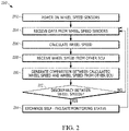
- FIG. 2 schematically illustrates a method 200 of operating the braking system 100 of FIG. 1 .
- the first ECU 102 provides power to the first wheel speed sensor 106 and the second wheel speed sensor 108 and the second ECU 104 provides power to the third wheel speed sensor 110 and the fourth wheel speed sensor 112.
- the first ECU 102 and the second ECU 104 each receive wheel speed data from the first wheel speed sensor 106, the second wheel speed sensor 108, the third wheel speed sensor 110, and the fourth wheel speed sensor 112.
- the first ECU 102 calculates, from the wheel speed data, a first wheel speed, a second wheel speed, a third wheel speed, and a fourth wheel speed.
- the second ECU 104 calculates, from the wheel speed data, a secondary first wheel speed, a secondary second wheel speed, a secondary third wheel speed, and a secondary fourth wheel speed.
- the first ECU 102 and the second ECU 104 exchange the calculated wheel speeds with each other over the communication link 118.
- the first ECU 102 transmits to the second ECU 104 the first wheel speed, the second wheel speed, the third wheel speed, and the fourth wheel speed and the second ECU 104 transmits to the first ECU 102 the secondary first wheel speed, the secondary second wheel speed, the secondary third wheel speed, and the secondary fourth wheel speed.
- the first ECU 102 and the second ECU 104 each, after receiving the calculated wheel speeds from the other, compare each of the calculated wheel speeds to the corresponding calculated wheel speed received from the other ECU. For example, the first ECU 102 compares the first wheel speed to the secondary first wheel speed, the second wheel speed to the secondary second wheel speed, the third wheel speed to the secondary third wheel speed, and the fourth wheel speed to the secondary fourth wheel speed.
- each of the first ECU 102 and the second ECU 104 determines a discrepancy in the comparisons (for example, if the wheel speeds of the comparison do not match).
- both ECUs 102 and 104 exchange a self-failsafe monitoring status (block 214).
- the self-failsafe monitoring status corresponds to the self-data monitoring and individual failsafe monitoring information described in more detail below in regard to FIG. 3 .
- the method 200 may return to block 204.
- both wheel speeds match (for example, within a predetermined deviation)
- the wheel speed monitoring continues again at block 204.
- FIG. 3 illustrates a table that illustrates one example of redundant self-data monitoring and individual failsafe monitoring performed by the first ECU 102 and the second ECU 104.
- the redundant self-data monitoring performed by both the first ECU 102 and the second ECU 104 for all four wheel speed sensors 106, 108, 110, and 112 includes wheel speed data calculation, wheel speed configuration, and direction information.
- the first ECU 102 and the second ECU 104 each perform individual self-failsafe monitoring on the wheel speed sensors they are directly coupled to.
- the first ECU 102 performs self-failsafe monitoring for the first wheel speed sensor 106 and the second wheel speed sensor 108.
- the second ECU 104 performs the same self-failsafe monitoring for the third wheel speed sensor 110 and the fourth wheel speed sensor 112.
- Individual self-failsafe monitoring includes, for example, wheel speed sensor testing, continuous voltage supply monitoring, line monitoring, air gap monitoring, pulse width monitoring, wheel speed monitoring, and high end timer buffer monitoring.
- Wheel speed sensor testing tests and verifies the supply voltage of the wheel speed sensors.
- Continuous voltage supply monitoring monitors the power supply (from the corresponding power supply 114 or 116) to the ECU.
- Line monitoring testing tests for electrical failures (for example, a short or open circuit) of the sensor between the voltage supply, signal, and the electric ground lines.
- Air gap monitoring verifies the distance between the wheel speed sensor and the tone ring is within a certain range for proper operation.
- the pulse width monitoring checks that the electrical signal from the wheel speed sensor has enough width (time) to be read properly.
- the wheel speed monitoring comparatively checks signals between the first, second, third, and fourth wheel speed sensors 106, 108, 110, and 112 to determine if the differences between the signals (i.e. time) are acceptable, for example, with respect to predetermined deviations or tolerances.
- the high end timer buffer monitor checks that the internal clock of the first ECU 102 and the second ECU 104 are not overflowing and are functioning properly.
- the redundant self-data monitoring and individual failsafe monitoring ensures both the first ECU 102 and the second ECU 104 have wheel speed sensor information during both typical operating conditions and degraded failsafe situations.
- the first ECU 102 and the second ECU 104 exchange self-failsafe monitoring status information (relating to any detected self errors/malfunctions) with each other over the communication link 118.
- both the first ECU 102 and the second ECU 104 keep similar valid, suspicious, and invalid flags between them.
- self-failsafe monitoring status information between the first ECU 102 and the second ECU 104, both the ECUs 102 and 104 can determine the accuracy/validity of information received from the other ECU over the communication link 118.
- the first ECU 102 and the second ECU 104 exchange self-data monitoring statuses repeatedly after a predetermined time number of seconds, for example 5ms.
- the first ECU 102 and the second ECU 104 perform individual power supply monitoring.
- the first ECU 102 is powered by the first power supply 114 and the second ECU 104 is powered by the second power supply 116.
- Both the ECUs 102, 104 monitor the power supply they are connected to (114 and 116 respectively.)
- the ECUs 102, 104 each determine, from the power supply monitoring of their power supply, a supply monitoring status for the first power supply 114 and the second power supply 116.
- the ECUs 102 and 104 exchange the supply monitoring status of the corresponding power supply 114 and 116.
- Power supply monitoring may include, for example, validation that the voltage supply to the first ECU 102 and the second ECU 104 is within a threshold or predetermined tolerance. In the case that the voltage supply of either ECU 102 or 104 is above or below a threshold, the ECU is shut down.
- the ECUs 102 and 104 may additionally be configured to monitor voltage supplied from the communication link 118 (for example, in the case the communication link 118 is a vehicle network bus) to be within a maximum and minimum threshold. Both ECUs 102 and 104 may further monitor voltage supplied to their internal components and devices they are connected to.
- the second ECU 104 may be connected to a temperature sensor and/or a position sensor monitoring the temperature and/or position of a brake booster of the second ECU 104.
- the ECUs 102 and 104 exchange individual power supply monitoring status information with each other over the communication link 118.
- the first ECU 102 and the second ECU 104 exchange battery supply monitoring statuses after every predetermined number of seconds, for example 5ms.
- embodiments provide, among other things, systems and methods for redundant wheel speed sensing.
- Various features and advantages of certain embodiments are set forth in the following claims.
Description
- Embodiments presented herein relate to the field of automotive control systems and, more particularly, to the monitoring of individual wheel speeds.
- Modern vehicles include electronic stability control, adaptive cruise control, collision avoidance systems, and other similar vehicle control systems that automatically apply the vehicle's brakes to control the speed and trajectory of a vehicle. The vehicle control systems are operated by one or more electronic control units ("ECUs") configured to receive inputs from sensors (for example, wheel speed sensors) and control components of the vehicle, for example, the vehicle's brakes. For example, a commercially-available stability control system sold under the brand name ESP by Robert Bosch GmbH, includes an ECU programmed to control a vehicle by applying braking forces to the wheels to improve vehicle stability. Other vehicles include a brake force booster ECU, which controls a vacuum-independent braking system booster. The ECUs (in the stability control system and the brake force booster) rely on an accurate indication of the vehicle's speed. The ECUs determine the vehicle's speed using data from one or more wheel speed sensors.
- Typically, a primary ECU (for example, the stability control system ECU) is directly coupled to the vehicle's wheel speed sensors. The primary ECU calculates, using data received from the sensors, the individual wheel speeds. The calculated wheel speeds are transmitted over a bus from the primary ECU to a secondary ECU (for example, a brake force booster ECU). The secondary ECU may further process the calculated wheel speeds and forward the processed data to other vehicle subsystems. In the event of a failure of the primary ECU, the secondary ECU will not receive the individual wheel speed data necessary to control the braking system. As a consequence, a human driver must manually apply the brakes to safely stop or control the vehicle. However, in highly-automated or autonomous vehicles, a human driver may not be able to manually apply the brakes in time to safely stop or control the vehicle.
US 2016/311419 A1 describes an autonomous vehicle control sub-system including first and second brake control modules that are communicatively and electrically connected to one another and a plurality of wheel-speed sensors communicatively connected to the first brake control module. The first module is programmed to receive wheel-speed data from the wheel-speed sensors. The second module is programmed to process the wheel-speed data in the event of a failure in the first module. - Therefore, embodiments described herein provide, among other things, systems and methods for redundant wheel speed sensing to continue providing wheel speed information to vehicle systems in the event of an ECU failure.
- The present invention provides a braking system according to claim 1, and a method of operating a braking system according to claim 9.
The system includes a first electronic control unit (102) connected to a first power supply (114);a second electronic control unit (104) connected to a second power supply (116), the second electronic control unit (104) communicatively coupled to the first electronic control unit (102);a first wheel speed sensor (106);a second wheel speed sensor (108);a third wheel speed sensor (110); and a fourth wheel speed sensor (112);wherein the first wheel speed sensor (106) and the second wheel speed sensor (108) are directly coupled to and powered by the first electronic control unit (102) and are communicatively coupled to the second electronic control unit (104);the third wheel speed sensor (110) and the fourth wheel speed sensor (112) are directly coupled to and powered by the second electronic control unit (104) and are communicatively coupled to the first electronic control unit (102); and the first electronic control unit (102) and the second electronic control unit (104) each configured to calculate a wheel speed from the first wheel speed sensor (106), the second wheel speed sensor (108), the third wheel speed sensor (110), and the fourth wheel speed sensor (112), wherein the second control unit is configured to receive second data from the first wheel speed sensor (106), the second wheel speed sensor (108), the third wheel speed sensor (110), and the fourth wheel speed sensor (112),the braking system (100) further comprising a second electronic processor configured to calculate from the second data a secondary first wheel speed, a secondary second wheel speed, a secondary third wheel speed, and a secondary fourth wheel speed;wherein the second electronic control unit (104) is configured to transmit the secondary first wheel speed, the secondary second wheel speed, the secondary third wheel speed, and the secondary fourth wheel speed to the first electronic control unit (102);wherein the first electronic control unit (102) and the second electronic control unit (104) are each configured:to generate a comparison of at least one of the first wheel speed, the second wheel speed, the third wheel speed, or the fourth wheel speed to at least one of the corresponding secondary first wheel speed, secondary second wheel speed, the secondary third wheel speed, or the secondary fourth wheel speed;to determine a discrepancy between the comparison;to exchange a self fail safe monitoring status; and to determine, from the self fail safe monitoring status, which between the first electronic control unit (102) and the second electronic control unit (104) is experiencing a failure. - The method includes providing power from a first power supply (114) to a first electronic control unit (102) providing, from the first electronic control unit (102), power to a first wheel speed sensor (106) and a second wheel speed sensor (108), the first wheel speed sensor (106) and the second wheel speed sensor (108) directly coupled to the first electronic control unit (102);providing power from a second power supply (116) to a second electronic control unit (104), the second electronic control unit (104) communicatively coupled to the first electronic control unit (102);providing, from the second electronic control unit (104), power to a third wheel speed sensor (110) and a fourth wheel speed sensor (112) directly coupled to the second electronic control unit (104);receiving, at the first electronic control unit (102), data from the first wheel speed sensor (106), the second wheel speed sensor (108), the third wheel speed sensor (110), and the fourth wheel speed sensor (112);calculating from the data, with an electronic processor, a first wheel speed, a second wheel speed, a third wheel speed, and a fourth wheel speed; and transmitting, from the first electronic control unit (102) to the second electronic control unit (104), the first wheel speed, the second wheel speed, the third wheel speed, and the fourth wheel speed;receiving, at the second electronic control unit (104), second data from the first wheel speed sensor (106), the second wheel speed sensor (108), the third wheel speed sensor (110), and the fourth wheel speed sensor (112);calculating, from the second data, with a second electronic processor a secondary first wheel speed, a secondary second wheel speed, a secondary third wheel speed, and a secondary fourth wheel speed; and transmitting, from the second electronic control unit (104) to the first electronic control unit (102), the secondary first wheel speed, the secondary second wheel speed, the secondary third wheel speed, and the secondary fourth wheel speed;generating a comparison of at least one of the first wheel speed, the second wheel speed, the third wheel speed, or the fourth wheel speed to at least one of the corresponding secondary first wheel speed, secondary second wheel speed, the secondary third wheel speed, or the secondary fourth wheel speed;determining a discrepancy between the comparison;exchanging a self fail safe monitoring status; and determining, from the self fail safe monitoring status, which between the first electronic control unit (102) and the second electronic control unit (104) is experiencing a failure.
- Other aspects of the invention will become apparent by consideration of the detailed description and accompanying drawings.
-
-
FIG. 1 is a schematic block diagram of a braking system according to one embodiment. -
FIG. 2 is a flowchart illustrating a method of operating the braking system ofFIG. 1 . -
FIG. 3 is a table illustrating types of redundant self-data monitoring and individual failsafe monitoring tests performed by an ECU of the braking system ofFIG. 1 . - Before any embodiments are explained in detail, it is to be understood that the embodiments are not limited in their application to the details of construction and the arrangement of components set forth in the following description or illustrated in the following drawings. Other embodiments are possible and the embodiments described are capable of being practiced or of being carried out in various ways.
- It should also be noted that a plurality of hardware and software based devices, as well as a plurality of different structural components may be used to implement various embodiments. In addition, it should be understood that embodiments may include hardware, software, and electronic components or modules that, for purposes of discussion, may be illustrated and described as if the majority of the components were implemented solely in hardware. However, one of ordinary skill in the art, and based on a reading of this detailed description, would recognize that, in at least one embodiment, the electronic based aspects of the invention may be implemented in software (e.g., stored on non-transitory computer-readable medium) executable by one or more processors. Therefore, it should be noted that a plurality of hardware and software based devices, as well as a plurality of different structural components may be utilized to implement the invention. For example, "control units" and "controllers" described in the specification can include one or more processors, one or more memory modules including non-transitory computer-readable medium, one or more input/output interfaces, and various connections (for example, a system bus) connecting the components.
-
FIG. 1 schematically illustrates anexample braking system 100 of avehicle 101 according to some embodiments. In some embodiments, thevehicle 101 is an autonomous vehicle. In one example, thebraking system 100 includes a first (electronic control unit) ECU 102, a second ECU 104, a firstwheel speed sensor 106, a secondwheel speed sensor 108, a thirdwheel speed sensor 110, a fourthwheel speed sensor 112, afirst power supply 114, and asecond power supply 116. The first ECU 102 and the second ECU 104 are communicatively coupled to each other via acommunication link 118. In other embodiments, particularly in vehicles with fewer or more than four wheels, a different number of components may be used. - In some embodiments, the first ECU 102 and the second ECU 104 include a plurality of electrical and electronic components that provide power, operational control, and protection to the components and modules within the first ECU 102 and the second ECU 104. The first ECU 102 and the second ECU 104 each include, among other things, an electronic processing unit (e.g., a microprocessor or another suitable programmable device), non-transitory memory (e.g., a computer-readable storage medium), and an input/output interface. The processing unit, the memory, and the input/output interface communicate over one or more control or data buses. It should be understood that the
first ECU 102 and thesecond ECU 104 may include additional, fewer, or different components. - In some embodiments, the first ECU 102 and the second ECU 104 are each implemented partially or entirely on a semiconductor (e.g., a field-programmable gate array ("FPGA") semiconductor) chip. The memory of the
first ECU 102 and thesecond ECU 104 can include a program storage area and a data storage area. The program storage area and the data storage area can include combinations of different types of memory, such as read-only memory ("ROM"), random access memory ("RAM"), or other suitable memory devices. The processing unit executes computer readable instructions ("software") stored in the memory. The software can include firmware, one or more applications, program data, filters, rules, one or more program modules, and other executable instructions. For example, the software can include instructions and associated data for controlling systems of thevehicle 101, such as thebraking system 100. - The first ECU 102 may be at least part of a primary braking system of the vehicle while the second ECU 104 is at least part of a secondary braking system of the vehicle. In some embodiments, the second ECU 104 is an electromechanical brake booster.
- Each of the
wheel speed sensors vehicle 101. Each of thewheel speed sensors wheel speed sensor 106 and the secondwheel speed sensor 108 are directly coupled to and powered by the first ECU 102. The thirdwheel speed sensor 110 and the fourthwheel speed sensor 112 are directly coupled to and powered by the second ECU 104. The first ECU 102 receives wheel speed data from the firstwheel speed sensor 106 and the secondwheel speed sensor 108 and the second ECU receives wheel speed data from the thirdwheel speed sensor 110 and the fourthwheel speed sensor 112. - The
first power supply 114 is directly coupled to the first ECU 102 to provide power to thefirst ECU 102. Likewise, thesecond power supply 116 is directly coupled to the second ECU 104 to provide power to thesecond ECU 104. Thefirst power supply 114 and thesecond power supply 116 operate independently of each other such that one may provide power when the other is unable to, for example, because of a malfunction. - The
communication link 118 may be a data bus, wired, wireless, or optical connection that enables the components to communicate with each using, for example, network communications protocols, for example, the CAN protocol. In some embodiments, thecommunication link 118 is controller area network bus or a deterministic communication bus such as a FlexRay bus. In some embodiments, the first ECU 102 and the second ECU 104 are synchronized and exchange information synchronously over thecommunication link 118. Thefirst ECU 102 and thesecond ECU 104 synchronize upon powering on thefirst ECU 102 and thesecond ECU 104 maintain synchronous communication while on. -
FIG. 2 schematically illustrates amethod 200 of operating thebraking system 100 ofFIG. 1 . Atblock 202, thefirst ECU 102 provides power to the firstwheel speed sensor 106 and the secondwheel speed sensor 108 and thesecond ECU 104 provides power to the thirdwheel speed sensor 110 and the fourthwheel speed sensor 112. Atblock 204, thefirst ECU 102 and thesecond ECU 104 each receive wheel speed data from the firstwheel speed sensor 106, the secondwheel speed sensor 108, the thirdwheel speed sensor 110, and the fourthwheel speed sensor 112. Atblock 206, thefirst ECU 102 calculates, from the wheel speed data, a first wheel speed, a second wheel speed, a third wheel speed, and a fourth wheel speed. Likewise, thesecond ECU 104 calculates, from the wheel speed data, a secondary first wheel speed, a secondary second wheel speed, a secondary third wheel speed, and a secondary fourth wheel speed. - At
block 208, thefirst ECU 102 and thesecond ECU 104 exchange the calculated wheel speeds with each other over thecommunication link 118. Thefirst ECU 102 transmits to thesecond ECU 104 the first wheel speed, the second wheel speed, the third wheel speed, and the fourth wheel speed and thesecond ECU 104 transmits to thefirst ECU 102 the secondary first wheel speed, the secondary second wheel speed, the secondary third wheel speed, and the secondary fourth wheel speed. Atblock 210, thefirst ECU 102 and thesecond ECU 104 each, after receiving the calculated wheel speeds from the other, compare each of the calculated wheel speeds to the corresponding calculated wheel speed received from the other ECU. For example, thefirst ECU 102 compares the first wheel speed to the secondary first wheel speed, the second wheel speed to the secondary second wheel speed, the third wheel speed to the secondary third wheel speed, and the fourth wheel speed to the secondary fourth wheel speed. - At
block 212, each of thefirst ECU 102 and thesecond ECU 104 determines a discrepancy in the comparisons (for example, if the wheel speeds of the comparison do not match). In the case of a discrepancy, bothECUs FIG. 3 . By exchanging such self-diagnostic information, it can be determined which between the first electronic control unit and the second electronic control unit is experiencing a failure and which of the two calculated wheel speeds is more reliable. After exchanging the self-failsafe monitoring status, themethod 200 may return to block 204. When both wheel speeds match (for example, within a predetermined deviation), the wheel speed monitoring continues again atblock 204. -
FIG. 3 illustrates a table that illustrates one example of redundant self-data monitoring and individual failsafe monitoring performed by thefirst ECU 102 and thesecond ECU 104. In the example, provided, the redundant self-data monitoring performed by both thefirst ECU 102 and thesecond ECU 104 for all fourwheel speed sensors - The
first ECU 102 and thesecond ECU 104 each perform individual self-failsafe monitoring on the wheel speed sensors they are directly coupled to. Thefirst ECU 102 performs self-failsafe monitoring for the firstwheel speed sensor 106 and the secondwheel speed sensor 108. Thesecond ECU 104 performs the same self-failsafe monitoring for the thirdwheel speed sensor 110 and the fourthwheel speed sensor 112. - Individual self-failsafe monitoring includes, for example, wheel speed sensor testing, continuous voltage supply monitoring, line monitoring, air gap monitoring, pulse width monitoring, wheel speed monitoring, and high end timer buffer monitoring. Wheel speed sensor testing tests and verifies the supply voltage of the wheel speed sensors. Continuous voltage supply monitoring monitors the power supply (from the
corresponding power supply 114 or 116) to the ECU. Line monitoring testing tests for electrical failures (for example, a short or open circuit) of the sensor between the voltage supply, signal, and the electric ground lines. Air gap monitoring verifies the distance between the wheel speed sensor and the tone ring is within a certain range for proper operation. The pulse width monitoring checks that the electrical signal from the wheel speed sensor has enough width (time) to be read properly. The wheel speed monitoring comparatively checks signals between the first, second, third, and fourthwheel speed sensors first ECU 102 and thesecond ECU 104 are not overflowing and are functioning properly. - The redundant self-data monitoring and individual failsafe monitoring ensures both the
first ECU 102 and thesecond ECU 104 have wheel speed sensor information during both typical operating conditions and degraded failsafe situations. Thefirst ECU 102 and thesecond ECU 104 exchange self-failsafe monitoring status information (relating to any detected self errors/malfunctions) with each other over thecommunication link 118. In one example, both thefirst ECU 102 and thesecond ECU 104 keep similar valid, suspicious, and invalid flags between them. By exchanging self-failsafe monitoring status information between thefirst ECU 102 and thesecond ECU 104, both theECUs communication link 118. In some embodiments, thefirst ECU 102 and thesecond ECU 104 exchange self-data monitoring statuses repeatedly after a predetermined time number of seconds, for example 5ms. - In some embodiments, the
first ECU 102 and thesecond ECU 104 perform individual power supply monitoring. As noted, thefirst ECU 102 is powered by thefirst power supply 114 and thesecond ECU 104 is powered by thesecond power supply 116. Both theECUs ECUs first power supply 114 and thesecond power supply 116. TheECUs corresponding power supply - Power supply monitoring may include, for example, validation that the voltage supply to the
first ECU 102 and thesecond ECU 104 is within a threshold or predetermined tolerance. In the case that the voltage supply of eitherECU ECUs communication link 118 is a vehicle network bus) to be within a maximum and minimum threshold. BothECUs second ECU 104 may be connected to a temperature sensor and/or a position sensor monitoring the temperature and/or position of a brake booster of thesecond ECU 104. Similar to embodiments discussed above in regard to the self-failsafe monitoring, theECUs communication link 118. In some embodiments, thefirst ECU 102 and thesecond ECU 104 exchange battery supply monitoring statuses after every predetermined number of seconds, for example 5ms. - Thus, embodiments provide, among other things, systems and methods for redundant wheel speed sensing. Various features and advantages of certain embodiments are set forth in the following claims.
Claims (10)
- A braking system (100) of a vehicle (101) comprising:a first electronic control unit (102) connected to a first power supply (114);a second electronic control unit (104) connected to a second power supply (116), the second electronic control unit (104) communicatively coupled to the first electronic control unit (102);a first wheel speed sensor (106);a second wheel speed sensor (108);a third wheel speed sensor (110); anda fourth wheel speed sensor (112);wherein the first wheel speed sensor (106) and the second wheel speed sensor (108) are directly coupled to and powered by the first electronic control unit (102) and are communicatively coupled to the second electronic control unit (104);the third wheel speed sensor (110) and the fourth wheel speed sensor (112) are directly coupled to and powered by the second electronic control unit (104) and are communicatively coupled to the first electronic control unit (102); andthe first electronic control unit (102) and the second electronic control unit (104) each configured to calculate a wheel speed from the first wheel speed sensor (106), the second wheel speed sensor (108), the third wheel speed sensor (110), and the fourth wheel speed sensor (112), wherein the second control unit is configured to receive second data from the first wheel speed sensor (106), the second wheel speed sensor (108), the third wheel speed sensor (110), and the fourth wheel speed sensor (112),the braking system (100) further comprising a second electronic processor configured to calculate from the second data a secondary first wheel speed, a secondary second wheel speed, a secondary third wheel speed, and a secondary fourth wheel speed;wherein the second electronic control unit (104) is configured to transmit the secondary first wheel speed, the secondary second wheel speed, the secondary third wheel speed, and the secondary fourth wheel speed to the first electronic control unit (102);characterized in thatthe first electronic control unit (102) and the second electronic control unit (104) are each configured:to generate a comparison of at least one of the first wheel speed, the second wheel speed, the third wheel speed, or the fourth wheel speed to at least one of the corresponding secondary first wheel speed, secondary second wheel speed, the secondary third wheel speed, or the secondary fourth wheel speed;to determine a discrepancy between the comparison;to exchange a self-failsafe monitoring status; andto determine, from the self-failsafe monitoring status, which between the first electronic control unit (102) and the second electronic control unit (104) is experiencing a failure.
- The braking system (100) of claim 1, wherein the first electronic control unit (102) and the second electronic control unit (104) are each configured to perform self-data monitoring.
- The braking system (100) of claim 2, wherein the first electronic control unit (102) and the second electronic control unit (104) each exchange information regarding self-data processing to each other.
- The braking system (100) of claim 1, wherein self-failsafe monitoring includes at least one selected from a group consisting of wheel speed sensor testing, continuous voltage supply monitoring, line monitoring, air gap monitoring, and pulse width monitoring.
- The braking system (100) of claim 1, wherein the first electronic control unit (102) and the second electronic control unit (104) communicate with each other via either a controller area network bus or a deterministic communication bus.
- The braking system (100) of claim 1, wherein the first electronic control unit (102) and the second electronic control unit (104) are synchronized with each other such that data is exchanged between them repeatedly after each of a predetermined time.
- The braking system (100) of claim 1, wherein the first electronic control unit (102) is a primary electronic control unit of the vehicle (101) and the second electronic control unit (104) is a secondary brake force booster electronic control unit.
- The braking system (100) of claim 1, wherein at least one of the first electronic control unit (102) or the second electronic control unit (104) is an electromechanical brake booster.
- A method (200) of operating a braking system (100), the method (200) comprising:providing power from a first power supply (114) to a first electronic control unit (102);providing, from the first electronic control unit (102), power to a first wheel speed sensor (106) and a second wheel speed sensor (108), the first wheel speed sensor (106) and the second wheel speed sensor (108) directly coupled to the first electronic control unit (102);providing power from a second power supply (116) to a second electronic control unit (104), the second electronic control unit (104) communicatively coupled to the first electronic control unit (102);providing, from the second electronic control unit (104), power to a third wheel speed sensor (110) and a fourth wheel speed sensor (112) directly coupled to the second electronic control unit (104);receiving, at the first electronic control unit (102), data from the first wheel speed sensor (106), the second wheel speed sensor (108), the third wheel speed sensor (110), and the fourth wheel speed sensor (112);calculating from the data, with an electronic processor, a first wheel speed, a second wheel speed, a third wheel speed, and a fourth wheel speed; andtransmitting, from the first electronic control unit (102) to the second electronic control unit (104), the first wheel speed, the second wheel speed, the third wheel speed, and the fourth wheel speed;receiving, at the second electronic control unit (104), second data from the first wheel speed sensor (106), the second wheel speed sensor (108), the third wheel speed sensor (110), and the fourth wheel speed sensor (112);calculating, from the second data, with a second electronic processor a secondary first wheel speed, a secondary second wheel speed, a secondary third wheel speed, and a secondary fourth wheel speed; andtransmitting, from the second electronic control unit (104) to the first electronic control unit (102), the secondary first wheel speed, the secondary second wheel speed, the secondary third wheel speed, and the secondary fourth wheel speed;generating a comparison of at least one of the first wheel speed, the second wheel speed, the third wheel speed, or the fourth wheel speed to at least one of the corresponding secondary first wheel speed, secondary second wheel speed, the secondary third wheel speed, or the secondary fourth wheel speed;determining a discrepancy between the comparison;exchanging a self-failsafe monitoring status; anddetermining, from the self-failsafe monitoring status, which between the first electronic control unit (102) and the second electronic control unit (104) is experiencing a failure.
- The method (200) of claim 9 further comprising, synchronizing communication between the first electronic control unit (102) and the second electronic control unit (104) upon powering on the first electronic control unit (102) and the second electronic control unit (104) and maintaining synchronous communication between the first electronic control unit (102) and the second electronic control unit (104).
Applications Claiming Priority (2)
| Application Number | Priority Date | Filing Date | Title |
|---|---|---|---|
| US15/679,188 US10486668B2 (en) | 2017-08-17 | 2017-08-17 | Systems and methods for redundant wheel speed sensing |
| PCT/EP2018/070914 WO2019034431A1 (en) | 2017-08-17 | 2018-08-01 | Systems and methods for redundant wheel speed sensing |
Publications (2)
| Publication Number | Publication Date |
|---|---|
| EP3668765A1 EP3668765A1 (en) | 2020-06-24 |
| EP3668765B1 true EP3668765B1 (en) | 2023-03-22 |
Family
ID=63113529
Family Applications (1)
| Application Number | Title | Priority Date | Filing Date |
|---|---|---|---|
| EP18750404.8A Active EP3668765B1 (en) | 2017-08-17 | 2018-08-01 | Systems and methods for redundant wheel speed sensing |
Country Status (5)
| Country | Link |
|---|---|
| US (1) | US10486668B2 (en) |
| EP (1) | EP3668765B1 (en) |
| KR (1) | KR102586265B1 (en) |
| CN (1) | CN110914120B (en) |
| WO (1) | WO2019034431A1 (en) |
Families Citing this family (15)
| Publication number | Priority date | Publication date | Assignee | Title |
|---|---|---|---|---|
| FR3074895B1 (en) * | 2017-12-08 | 2020-01-03 | Safran Landing Systems | DEVICE FOR MEASURING ROTATION SPEEDS OF AT LEAST TWO WHEELS OF AN AIRCRAFT LANDER |
| DE102018218837B4 (en) * | 2018-11-05 | 2020-06-18 | Mando Corporation | Wheel speed sensor system, a vehicle including the wheel speed sensor system, and method for processing wheel speed signals |
| DE102019106243A1 (en) * | 2019-03-12 | 2020-09-17 | Wabco Gmbh | Electropneumatic braking system for commercial vehicles |
| DE102019106591A1 (en) | 2019-03-15 | 2020-09-17 | Wabco Gmbh | Electronically controllable braking system with two fall-back levels |
| DE102019206669A1 (en) * | 2019-05-09 | 2020-11-12 | Robert Bosch Gmbh | Control unit and method for operating a brake actuator of a vehicle |
| CN110244685A (en) * | 2019-05-13 | 2019-09-17 | 思与行科技(苏州)有限公司 | The safety control circuit of controller for active electronic braking system |
| DE102019210271A1 (en) * | 2019-07-11 | 2021-01-14 | Robert Bosch Gmbh | Brake system and method for braking a motor vehicle |
| EP4028301A4 (en) * | 2019-09-12 | 2023-11-08 | Thales Canada Inc. | Over-speed protection device |
| DE102020205961A1 (en) * | 2019-11-06 | 2021-05-06 | Robert Bosch Gesellschaft mit beschränkter Haftung | Sensor arrangement for a vehicle and multi-circuit braking system |
| FR3104097B1 (en) * | 2019-12-05 | 2021-12-24 | Foundation Brakes France | Interface between wheel speed sensor and braking circuit |
| KR20210114587A (en) * | 2020-03-10 | 2021-09-24 | 현대모비스 주식회사 | Apparatus for determining wheel condition and method thereof |
| KR20210147487A (en) * | 2020-05-29 | 2021-12-07 | 현대모비스 주식회사 | Vehicle Braking Apparatus |
| KR20220121284A (en) | 2021-02-24 | 2022-09-01 | 현대자동차주식회사 | Apparatus for examining for damage of drivetrain of vehicle and method thereof |
| DE102021108523A1 (en) * | 2021-04-06 | 2022-10-06 | Audi Aktiengesellschaft | Braking system for an autonomous vehicle |
| EP4194291B1 (en) | 2021-12-09 | 2023-11-29 | Volvo Truck Corporation | Redundant wheel speed sensors in a single package |
Family Cites Families (10)
| Publication number | Priority date | Publication date | Assignee | Title |
|---|---|---|---|---|
| DE19861144C2 (en) * | 1998-06-12 | 2003-10-09 | Bosch Gmbh Robert | Electric braking system for a motor vehicle |
| DE102007029632A1 (en) * | 2006-06-27 | 2008-01-10 | Continental Teves Ag & Co. Ohg | Parking brake system for motor vehicle, has control element and two electromechanical actuators for generating parking brake force on respective wheel of vehicle, where control element is connected to electromechanical actuators |
| KR100911547B1 (en) * | 2007-12-06 | 2009-08-10 | 현대자동차주식회사 | A wheel speed sensor protecting apparatus |
| GB0802212D0 (en) * | 2008-02-06 | 2008-03-12 | Meritor Heavy Vehicle Braking | A brake system and method |
| US9128130B2 (en) * | 2011-09-15 | 2015-09-08 | Schweitzer Engineering Laboratories, Inc. | Systems and methods for synchronizing distributed generation systems |
| DE102012010562B4 (en) * | 2012-05-26 | 2013-12-24 | Audi Ag | Parking brake system for a vehicle |
| JP5961513B2 (en) * | 2012-09-28 | 2016-08-02 | 日立オートモティブシステムズ株式会社 | Vehicle control device and brake control device |
| US9218695B2 (en) * | 2012-12-27 | 2015-12-22 | Robert Bosch Gmbh | System and method for monitoring an estimated wheel speed of a vehicle using a transmission output shaft sensor |
| US9527487B2 (en) | 2014-07-11 | 2016-12-27 | Ford Global Technologies, Llc | Failure tolerant vehicle speed |
| JP6128143B2 (en) * | 2015-02-18 | 2017-05-17 | トヨタ自動車株式会社 | Tire pressure monitoring system |
-
2017
- 2017-08-17 US US15/679,188 patent/US10486668B2/en active Active
-
2018
- 2018-08-01 WO PCT/EP2018/070914 patent/WO2019034431A1/en unknown
- 2018-08-01 CN CN201880053007.6A patent/CN110914120B/en active Active
- 2018-08-01 KR KR1020207004473A patent/KR102586265B1/en active IP Right Grant
- 2018-08-01 EP EP18750404.8A patent/EP3668765B1/en active Active
Also Published As
| Publication number | Publication date |
|---|---|
| KR20200038478A (en) | 2020-04-13 |
| EP3668765A1 (en) | 2020-06-24 |
| US10486668B2 (en) | 2019-11-26 |
| US20190054909A1 (en) | 2019-02-21 |
| CN110914120A (en) | 2020-03-24 |
| KR102586265B1 (en) | 2023-10-11 |
| WO2019034431A1 (en) | 2019-02-21 |
| CN110914120B (en) | 2022-06-07 |
Similar Documents
| Publication | Publication Date | Title |
|---|---|---|
| EP3668765B1 (en) | Systems and methods for redundant wheel speed sensing | |
| EP3085596B1 (en) | A vehicle safety electronic control system | |
| US20180290642A1 (en) | Device for controlling a safety-relevant process, method for testing the functionality of the device, and motor vehicle with the device | |
| US9003271B2 (en) | Error detecting device and method of a dual controller system | |
| US11643095B2 (en) | Electronic control device, control system, and reset determination method | |
| US9880911B2 (en) | Method for handling faults in a central control device, and control device | |
| CN105659532B (en) | Electrical subsystem, message filter and method for a vehicle | |
| JP2019128639A (en) | Electronic control device | |
| US20210347370A1 (en) | Vehicle Control System | |
| KR20200022674A (en) | Apparatus for controlling fail-operational of vehicle, and method thereof | |
| KR20180064422A (en) | Vehicle safety electronic control system | |
| US11066080B2 (en) | Vehicle control device and electronic control system | |
| US20220055636A1 (en) | Control Architecture for a Vehicle | |
| EP3626571B1 (en) | Control architecture for a vehicle | |
| KR101203872B1 (en) | Error detection apparatus and method for dual microcontroller system | |
| KR20180130475A (en) | Apparatus and method for monitoring Microcontroller Unit | |
| EP3869338A1 (en) | A vehicle safety electronic control system | |
| CN112550313A (en) | Fault-tolerant embedded automotive application through cloud computing | |
| US20220371565A1 (en) | Switching device for a brake system for a vehicle, brake system with a switching device and method for operating a switching device | |
| JP3916495B2 (en) | Controller with fail-safe function | |
| CN111619477B (en) | Communication system and communication method for motor vehicle communication | |
| US20240129364A1 (en) | Gateway for connection to a host processor and multiple slaves and method for operating the gateway | |
| CN115987442A (en) | Distributed automatic driving control system and time synchronization method thereof | |
| KR20230168349A (en) | Device and Method for Detecting Short-circuit between Sub-systems in Distribution System, and Distribution System including the same | |
| CN114655178A (en) | Vehicle braking system and vehicle braking method |
Legal Events
| Date | Code | Title | Description |
|---|---|---|---|
| STAA | Information on the status of an ep patent application or granted ep patent |
Free format text: STATUS: UNKNOWN |
|
| STAA | Information on the status of an ep patent application or granted ep patent |
Free format text: STATUS: THE INTERNATIONAL PUBLICATION HAS BEEN MADE |
|
| PUAI | Public reference made under article 153(3) epc to a published international application that has entered the european phase |
Free format text: ORIGINAL CODE: 0009012 |
|
| STAA | Information on the status of an ep patent application or granted ep patent |
Free format text: STATUS: REQUEST FOR EXAMINATION WAS MADE |
|
| 17P | Request for examination filed |
Effective date: 20200317 |
|
| AK | Designated contracting states |
Kind code of ref document: A1 Designated state(s): AL AT BE BG CH CY CZ DE DK EE ES FI FR GB GR HR HU IE IS IT LI LT LU LV MC MK MT NL NO PL PT RO RS SE SI SK SM TR |
|
| AX | Request for extension of the european patent |
Extension state: BA ME |
|
| DAV | Request for validation of the european patent (deleted) | ||
| DAX | Request for extension of the european patent (deleted) | ||
| GRAP | Despatch of communication of intention to grant a patent |
Free format text: ORIGINAL CODE: EPIDOSNIGR1 |
|
| STAA | Information on the status of an ep patent application or granted ep patent |
Free format text: STATUS: GRANT OF PATENT IS INTENDED |
|
| INTG | Intention to grant announced |
Effective date: 20221121 |
|
| GRAS | Grant fee paid |
Free format text: ORIGINAL CODE: EPIDOSNIGR3 |
|
| GRAA | (expected) grant |
Free format text: ORIGINAL CODE: 0009210 |
|
| STAA | Information on the status of an ep patent application or granted ep patent |
Free format text: STATUS: THE PATENT HAS BEEN GRANTED |
|
| AK | Designated contracting states |
Kind code of ref document: B1 Designated state(s): AL AT BE BG CH CY CZ DE DK EE ES FI FR GB GR HR HU IE IS IT LI LT LU LV MC MK MT NL NO PL PT RO RS SE SI SK SM TR |
|
| REG | Reference to a national code |
Ref country code: GB Ref legal event code: FG4D |
|
| REG | Reference to a national code |
Ref country code: CH Ref legal event code: EP |
|
| REG | Reference to a national code |
Ref country code: IE Ref legal event code: FG4D |
|
| REG | Reference to a national code |
Ref country code: DE Ref legal event code: R096 Ref document number: 602018047490 Country of ref document: DE |
|
| REG | Reference to a national code |
Ref country code: AT Ref legal event code: REF Ref document number: 1555131 Country of ref document: AT Kind code of ref document: T Effective date: 20230415 |
|
| REG | Reference to a national code |
Ref country code: LT Ref legal event code: MG9D |
|
| REG | Reference to a national code |
Ref country code: NL Ref legal event code: MP Effective date: 20230322 |
|
| PG25 | Lapsed in a contracting state [announced via postgrant information from national office to epo] |
Ref country code: RS Free format text: LAPSE BECAUSE OF FAILURE TO SUBMIT A TRANSLATION OF THE DESCRIPTION OR TO PAY THE FEE WITHIN THE PRESCRIBED TIME-LIMIT Effective date: 20230322 Ref country code: NO Free format text: LAPSE BECAUSE OF FAILURE TO SUBMIT A TRANSLATION OF THE DESCRIPTION OR TO PAY THE FEE WITHIN THE PRESCRIBED TIME-LIMIT Effective date: 20230622 Ref country code: LV Free format text: LAPSE BECAUSE OF FAILURE TO SUBMIT A TRANSLATION OF THE DESCRIPTION OR TO PAY THE FEE WITHIN THE PRESCRIBED TIME-LIMIT Effective date: 20230322 Ref country code: LT Free format text: LAPSE BECAUSE OF FAILURE TO SUBMIT A TRANSLATION OF THE DESCRIPTION OR TO PAY THE FEE WITHIN THE PRESCRIBED TIME-LIMIT Effective date: 20230322 Ref country code: HR Free format text: LAPSE BECAUSE OF FAILURE TO SUBMIT A TRANSLATION OF THE DESCRIPTION OR TO PAY THE FEE WITHIN THE PRESCRIBED TIME-LIMIT Effective date: 20230322 |
|
| REG | Reference to a national code |
Ref country code: AT Ref legal event code: MK05 Ref document number: 1555131 Country of ref document: AT Kind code of ref document: T Effective date: 20230322 |
|
| PG25 | Lapsed in a contracting state [announced via postgrant information from national office to epo] |
Ref country code: SE Free format text: LAPSE BECAUSE OF FAILURE TO SUBMIT A TRANSLATION OF THE DESCRIPTION OR TO PAY THE FEE WITHIN THE PRESCRIBED TIME-LIMIT Effective date: 20230322 Ref country code: NL Free format text: LAPSE BECAUSE OF FAILURE TO SUBMIT A TRANSLATION OF THE DESCRIPTION OR TO PAY THE FEE WITHIN THE PRESCRIBED TIME-LIMIT Effective date: 20230322 Ref country code: GR Free format text: LAPSE BECAUSE OF FAILURE TO SUBMIT A TRANSLATION OF THE DESCRIPTION OR TO PAY THE FEE WITHIN THE PRESCRIBED TIME-LIMIT Effective date: 20230623 Ref country code: FI Free format text: LAPSE BECAUSE OF FAILURE TO SUBMIT A TRANSLATION OF THE DESCRIPTION OR TO PAY THE FEE WITHIN THE PRESCRIBED TIME-LIMIT Effective date: 20230322 |
|
| PG25 | Lapsed in a contracting state [announced via postgrant information from national office to epo] |
Ref country code: SM Free format text: LAPSE BECAUSE OF FAILURE TO SUBMIT A TRANSLATION OF THE DESCRIPTION OR TO PAY THE FEE WITHIN THE PRESCRIBED TIME-LIMIT Effective date: 20230322 Ref country code: RO Free format text: LAPSE BECAUSE OF FAILURE TO SUBMIT A TRANSLATION OF THE DESCRIPTION OR TO PAY THE FEE WITHIN THE PRESCRIBED TIME-LIMIT Effective date: 20230322 Ref country code: PT Free format text: LAPSE BECAUSE OF FAILURE TO SUBMIT A TRANSLATION OF THE DESCRIPTION OR TO PAY THE FEE WITHIN THE PRESCRIBED TIME-LIMIT Effective date: 20230724 Ref country code: ES Free format text: LAPSE BECAUSE OF FAILURE TO SUBMIT A TRANSLATION OF THE DESCRIPTION OR TO PAY THE FEE WITHIN THE PRESCRIBED TIME-LIMIT Effective date: 20230322 Ref country code: EE Free format text: LAPSE BECAUSE OF FAILURE TO SUBMIT A TRANSLATION OF THE DESCRIPTION OR TO PAY THE FEE WITHIN THE PRESCRIBED TIME-LIMIT Effective date: 20230322 Ref country code: AT Free format text: LAPSE BECAUSE OF FAILURE TO SUBMIT A TRANSLATION OF THE DESCRIPTION OR TO PAY THE FEE WITHIN THE PRESCRIBED TIME-LIMIT Effective date: 20230322 |
|
| PGFP | Annual fee paid to national office [announced via postgrant information from national office to epo] |
Ref country code: IT Payment date: 20230831 Year of fee payment: 6 |
|
| PG25 | Lapsed in a contracting state [announced via postgrant information from national office to epo] |
Ref country code: SK Free format text: LAPSE BECAUSE OF FAILURE TO SUBMIT A TRANSLATION OF THE DESCRIPTION OR TO PAY THE FEE WITHIN THE PRESCRIBED TIME-LIMIT Effective date: 20230322 Ref country code: PL Free format text: LAPSE BECAUSE OF FAILURE TO SUBMIT A TRANSLATION OF THE DESCRIPTION OR TO PAY THE FEE WITHIN THE PRESCRIBED TIME-LIMIT Effective date: 20230322 Ref country code: IS Free format text: LAPSE BECAUSE OF FAILURE TO SUBMIT A TRANSLATION OF THE DESCRIPTION OR TO PAY THE FEE WITHIN THE PRESCRIBED TIME-LIMIT Effective date: 20230722 |
|
| PGFP | Annual fee paid to national office [announced via postgrant information from national office to epo] |
Ref country code: FR Payment date: 20230821 Year of fee payment: 6 |
|
| REG | Reference to a national code |
Ref country code: DE Ref legal event code: R097 Ref document number: 602018047490 Country of ref document: DE |
|
| PLBE | No opposition filed within time limit |
Free format text: ORIGINAL CODE: 0009261 |
|
| STAA | Information on the status of an ep patent application or granted ep patent |
Free format text: STATUS: NO OPPOSITION FILED WITHIN TIME LIMIT |
|
| PG25 | Lapsed in a contracting state [announced via postgrant information from national office to epo] |
Ref country code: SI Free format text: LAPSE BECAUSE OF FAILURE TO SUBMIT A TRANSLATION OF THE DESCRIPTION OR TO PAY THE FEE WITHIN THE PRESCRIBED TIME-LIMIT Effective date: 20230322 Ref country code: DK Free format text: LAPSE BECAUSE OF FAILURE TO SUBMIT A TRANSLATION OF THE DESCRIPTION OR TO PAY THE FEE WITHIN THE PRESCRIBED TIME-LIMIT Effective date: 20230322 Ref country code: CZ Free format text: LAPSE BECAUSE OF FAILURE TO SUBMIT A TRANSLATION OF THE DESCRIPTION OR TO PAY THE FEE WITHIN THE PRESCRIBED TIME-LIMIT Effective date: 20230322 |
|
| PGFP | Annual fee paid to national office [announced via postgrant information from national office to epo] |
Ref country code: DE Payment date: 20231025 Year of fee payment: 6 |
|
| 26N | No opposition filed |
Effective date: 20240102 |
|
| PG25 | Lapsed in a contracting state [announced via postgrant information from national office to epo] |
Ref country code: MC Free format text: LAPSE BECAUSE OF FAILURE TO SUBMIT A TRANSLATION OF THE DESCRIPTION OR TO PAY THE FEE WITHIN THE PRESCRIBED TIME-LIMIT Effective date: 20230322 |
|
| REG | Reference to a national code |
Ref country code: CH Ref legal event code: PL |
|
| PG25 | Lapsed in a contracting state [announced via postgrant information from national office to epo] |
Ref country code: MC Free format text: LAPSE BECAUSE OF FAILURE TO SUBMIT A TRANSLATION OF THE DESCRIPTION OR TO PAY THE FEE WITHIN THE PRESCRIBED TIME-LIMIT Effective date: 20230322 |
|
| PG25 | Lapsed in a contracting state [announced via postgrant information from national office to epo] |
Ref country code: LU Free format text: LAPSE BECAUSE OF NON-PAYMENT OF DUE FEES Effective date: 20230801 |