KR20220121284A - Apparatus for examining for damage of drivetrain of vehicle and method thereof - Google Patents
Apparatus for examining for damage of drivetrain of vehicle and method thereof Download PDFInfo
- Publication number
- KR20220121284A KR20220121284A KR1020210024934A KR20210024934A KR20220121284A KR 20220121284 A KR20220121284 A KR 20220121284A KR 1020210024934 A KR1020210024934 A KR 1020210024934A KR 20210024934 A KR20210024934 A KR 20210024934A KR 20220121284 A KR20220121284 A KR 20220121284A
- Authority
- KR
- South Korea
- Prior art keywords
- motor
- hardware
- disconnector
- drive wheel
- vehicle
- Prior art date
Links
- 238000000034 method Methods 0.000 title claims abstract description 52
- 238000003745 diagnosis Methods 0.000 claims abstract description 23
- 230000005540 biological transmission Effects 0.000 claims abstract description 13
- 230000008859 change Effects 0.000 claims description 30
- 230000001133 acceleration Effects 0.000 claims description 6
- 238000010586 diagram Methods 0.000 description 8
- 230000008878 coupling Effects 0.000 description 4
- 238000010168 coupling process Methods 0.000 description 4
- 238000005859 coupling reaction Methods 0.000 description 4
- 230000008569 process Effects 0.000 description 4
- 230000015556 catabolic process Effects 0.000 description 3
- 230000000694 effects Effects 0.000 description 2
- 238000005516 engineering process Methods 0.000 description 2
- 230000006870 function Effects 0.000 description 2
- 230000002265 prevention Effects 0.000 description 2
- 230000009471 action Effects 0.000 description 1
- 230000000903 blocking effect Effects 0.000 description 1
- 238000004364 calculation method Methods 0.000 description 1
- 238000004891 communication Methods 0.000 description 1
- 238000011161 development Methods 0.000 description 1
- 230000005611 electricity Effects 0.000 description 1
- 239000000446 fuel Substances 0.000 description 1
- 230000007257 malfunction Effects 0.000 description 1
- 238000012986 modification Methods 0.000 description 1
- 230000004048 modification Effects 0.000 description 1
- 238000012545 processing Methods 0.000 description 1
Images


Classifications
-
- B—PERFORMING OPERATIONS; TRANSPORTING
- B60—VEHICLES IN GENERAL
- B60W—CONJOINT CONTROL OF VEHICLE SUB-UNITS OF DIFFERENT TYPE OR DIFFERENT FUNCTION; CONTROL SYSTEMS SPECIALLY ADAPTED FOR HYBRID VEHICLES; ROAD VEHICLE DRIVE CONTROL SYSTEMS FOR PURPOSES NOT RELATED TO THE CONTROL OF A PARTICULAR SUB-UNIT
- B60W50/00—Details of control systems for road vehicle drive control not related to the control of a particular sub-unit, e.g. process diagnostic or vehicle driver interfaces
- B60W50/02—Ensuring safety in case of control system failures, e.g. by diagnosing, circumventing or fixing failures
- B60W50/0205—Diagnosing or detecting failures; Failure detection models
-
- B—PERFORMING OPERATIONS; TRANSPORTING
- B60—VEHICLES IN GENERAL
- B60K—ARRANGEMENT OR MOUNTING OF PROPULSION UNITS OR OF TRANSMISSIONS IN VEHICLES; ARRANGEMENT OR MOUNTING OF PLURAL DIVERSE PRIME-MOVERS IN VEHICLES; AUXILIARY DRIVES FOR VEHICLES; INSTRUMENTATION OR DASHBOARDS FOR VEHICLES; ARRANGEMENTS IN CONNECTION WITH COOLING, AIR INTAKE, GAS EXHAUST OR FUEL SUPPLY OF PROPULSION UNITS IN VEHICLES
- B60K35/00—Arrangement of adaptations of instruments
-
- B—PERFORMING OPERATIONS; TRANSPORTING
- B60—VEHICLES IN GENERAL
- B60K—ARRANGEMENT OR MOUNTING OF PROPULSION UNITS OR OF TRANSMISSIONS IN VEHICLES; ARRANGEMENT OR MOUNTING OF PLURAL DIVERSE PRIME-MOVERS IN VEHICLES; AUXILIARY DRIVES FOR VEHICLES; INSTRUMENTATION OR DASHBOARDS FOR VEHICLES; ARRANGEMENTS IN CONNECTION WITH COOLING, AIR INTAKE, GAS EXHAUST OR FUEL SUPPLY OF PROPULSION UNITS IN VEHICLES
- B60K17/00—Arrangement or mounting of transmissions in vehicles
- B60K17/34—Arrangement or mounting of transmissions in vehicles for driving both front and rear wheels, e.g. four wheel drive vehicles
- B60K17/348—Arrangement or mounting of transmissions in vehicles for driving both front and rear wheels, e.g. four wheel drive vehicles having differential means for driving one set of wheels, e.g. the front, at one speed and the other set, e.g. the rear, at a different speed
- B60K17/35—Arrangement or mounting of transmissions in vehicles for driving both front and rear wheels, e.g. four wheel drive vehicles having differential means for driving one set of wheels, e.g. the front, at one speed and the other set, e.g. the rear, at a different speed including arrangements for suppressing or influencing the power transfer, e.g. viscous clutches
-
- B—PERFORMING OPERATIONS; TRANSPORTING
- B60—VEHICLES IN GENERAL
- B60K—ARRANGEMENT OR MOUNTING OF PROPULSION UNITS OR OF TRANSMISSIONS IN VEHICLES; ARRANGEMENT OR MOUNTING OF PLURAL DIVERSE PRIME-MOVERS IN VEHICLES; AUXILIARY DRIVES FOR VEHICLES; INSTRUMENTATION OR DASHBOARDS FOR VEHICLES; ARRANGEMENTS IN CONNECTION WITH COOLING, AIR INTAKE, GAS EXHAUST OR FUEL SUPPLY OF PROPULSION UNITS IN VEHICLES
- B60K23/00—Arrangement or mounting of control devices for vehicle transmissions, or parts thereof, not otherwise provided for
- B60K23/08—Arrangement or mounting of control devices for vehicle transmissions, or parts thereof, not otherwise provided for for changing number of driven wheels, for switching from driving one axle to driving two or more axles
- B60K23/0808—Arrangement or mounting of control devices for vehicle transmissions, or parts thereof, not otherwise provided for for changing number of driven wheels, for switching from driving one axle to driving two or more axles for varying torque distribution between driven axles, e.g. by transfer clutch
-
- B—PERFORMING OPERATIONS; TRANSPORTING
- B60—VEHICLES IN GENERAL
- B60K—ARRANGEMENT OR MOUNTING OF PROPULSION UNITS OR OF TRANSMISSIONS IN VEHICLES; ARRANGEMENT OR MOUNTING OF PLURAL DIVERSE PRIME-MOVERS IN VEHICLES; AUXILIARY DRIVES FOR VEHICLES; INSTRUMENTATION OR DASHBOARDS FOR VEHICLES; ARRANGEMENTS IN CONNECTION WITH COOLING, AIR INTAKE, GAS EXHAUST OR FUEL SUPPLY OF PROPULSION UNITS IN VEHICLES
- B60K7/00—Disposition of motor in, or adjacent to, traction wheel
- B60K7/0007—Disposition of motor in, or adjacent to, traction wheel the motor being electric
-
- B—PERFORMING OPERATIONS; TRANSPORTING
- B60—VEHICLES IN GENERAL
- B60L—PROPULSION OF ELECTRICALLY-PROPELLED VEHICLES; SUPPLYING ELECTRIC POWER FOR AUXILIARY EQUIPMENT OF ELECTRICALLY-PROPELLED VEHICLES; ELECTRODYNAMIC BRAKE SYSTEMS FOR VEHICLES IN GENERAL; MAGNETIC SUSPENSION OR LEVITATION FOR VEHICLES; MONITORING OPERATING VARIABLES OF ELECTRICALLY-PROPELLED VEHICLES; ELECTRIC SAFETY DEVICES FOR ELECTRICALLY-PROPELLED VEHICLES
- B60L1/00—Supplying electric power to auxiliary equipment of vehicles
- B60L1/003—Supplying electric power to auxiliary equipment of vehicles to auxiliary motors, e.g. for pumps, compressors
-
- B—PERFORMING OPERATIONS; TRANSPORTING
- B60—VEHICLES IN GENERAL
- B60L—PROPULSION OF ELECTRICALLY-PROPELLED VEHICLES; SUPPLYING ELECTRIC POWER FOR AUXILIARY EQUIPMENT OF ELECTRICALLY-PROPELLED VEHICLES; ELECTRODYNAMIC BRAKE SYSTEMS FOR VEHICLES IN GENERAL; MAGNETIC SUSPENSION OR LEVITATION FOR VEHICLES; MONITORING OPERATING VARIABLES OF ELECTRICALLY-PROPELLED VEHICLES; ELECTRIC SAFETY DEVICES FOR ELECTRICALLY-PROPELLED VEHICLES
- B60L3/00—Electric devices on electrically-propelled vehicles for safety purposes; Monitoring operating variables, e.g. speed, deceleration or energy consumption
- B60L3/0023—Detecting, eliminating, remedying or compensating for drive train abnormalities, e.g. failures within the drive train
- B60L3/003—Detecting, eliminating, remedying or compensating for drive train abnormalities, e.g. failures within the drive train relating to inverters
-
- B—PERFORMING OPERATIONS; TRANSPORTING
- B60—VEHICLES IN GENERAL
- B60L—PROPULSION OF ELECTRICALLY-PROPELLED VEHICLES; SUPPLYING ELECTRIC POWER FOR AUXILIARY EQUIPMENT OF ELECTRICALLY-PROPELLED VEHICLES; ELECTRODYNAMIC BRAKE SYSTEMS FOR VEHICLES IN GENERAL; MAGNETIC SUSPENSION OR LEVITATION FOR VEHICLES; MONITORING OPERATING VARIABLES OF ELECTRICALLY-PROPELLED VEHICLES; ELECTRIC SAFETY DEVICES FOR ELECTRICALLY-PROPELLED VEHICLES
- B60L3/00—Electric devices on electrically-propelled vehicles for safety purposes; Monitoring operating variables, e.g. speed, deceleration or energy consumption
- B60L3/0023—Detecting, eliminating, remedying or compensating for drive train abnormalities, e.g. failures within the drive train
- B60L3/0061—Detecting, eliminating, remedying or compensating for drive train abnormalities, e.g. failures within the drive train relating to electrical machines
-
- B—PERFORMING OPERATIONS; TRANSPORTING
- B60—VEHICLES IN GENERAL
- B60L—PROPULSION OF ELECTRICALLY-PROPELLED VEHICLES; SUPPLYING ELECTRIC POWER FOR AUXILIARY EQUIPMENT OF ELECTRICALLY-PROPELLED VEHICLES; ELECTRODYNAMIC BRAKE SYSTEMS FOR VEHICLES IN GENERAL; MAGNETIC SUSPENSION OR LEVITATION FOR VEHICLES; MONITORING OPERATING VARIABLES OF ELECTRICALLY-PROPELLED VEHICLES; ELECTRIC SAFETY DEVICES FOR ELECTRICALLY-PROPELLED VEHICLES
- B60L50/00—Electric propulsion with power supplied within the vehicle
- B60L50/50—Electric propulsion with power supplied within the vehicle using propulsion power supplied by batteries or fuel cells
- B60L50/60—Electric propulsion with power supplied within the vehicle using propulsion power supplied by batteries or fuel cells using power supplied by batteries
-
- B—PERFORMING OPERATIONS; TRANSPORTING
- B60—VEHICLES IN GENERAL
- B60W—CONJOINT CONTROL OF VEHICLE SUB-UNITS OF DIFFERENT TYPE OR DIFFERENT FUNCTION; CONTROL SYSTEMS SPECIALLY ADAPTED FOR HYBRID VEHICLES; ROAD VEHICLE DRIVE CONTROL SYSTEMS FOR PURPOSES NOT RELATED TO THE CONTROL OF A PARTICULAR SUB-UNIT
- B60W10/00—Conjoint control of vehicle sub-units of different type or different function
- B60W10/04—Conjoint control of vehicle sub-units of different type or different function including control of propulsion units
- B60W10/08—Conjoint control of vehicle sub-units of different type or different function including control of propulsion units including control of electric propulsion units, e.g. motors or generators
-
- B—PERFORMING OPERATIONS; TRANSPORTING
- B60—VEHICLES IN GENERAL
- B60W—CONJOINT CONTROL OF VEHICLE SUB-UNITS OF DIFFERENT TYPE OR DIFFERENT FUNCTION; CONTROL SYSTEMS SPECIALLY ADAPTED FOR HYBRID VEHICLES; ROAD VEHICLE DRIVE CONTROL SYSTEMS FOR PURPOSES NOT RELATED TO THE CONTROL OF A PARTICULAR SUB-UNIT
- B60W30/00—Purposes of road vehicle drive control systems not related to the control of a particular sub-unit, e.g. of systems using conjoint control of vehicle sub-units, or advanced driver assistance systems for ensuring comfort, stability and safety or drive control systems for propelling or retarding the vehicle
- B60W30/18—Propelling the vehicle
- B60W30/184—Preventing damage resulting from overload or excessive wear of the driveline
- B60W30/1846—Preventing of breakage of drive line components, e.g. parts of the gearing
-
- B—PERFORMING OPERATIONS; TRANSPORTING
- B60—VEHICLES IN GENERAL
- B60W—CONJOINT CONTROL OF VEHICLE SUB-UNITS OF DIFFERENT TYPE OR DIFFERENT FUNCTION; CONTROL SYSTEMS SPECIALLY ADAPTED FOR HYBRID VEHICLES; ROAD VEHICLE DRIVE CONTROL SYSTEMS FOR PURPOSES NOT RELATED TO THE CONTROL OF A PARTICULAR SUB-UNIT
- B60W40/00—Estimation or calculation of non-directly measurable driving parameters for road vehicle drive control systems not related to the control of a particular sub unit, e.g. by using mathematical models
- B60W40/10—Estimation or calculation of non-directly measurable driving parameters for road vehicle drive control systems not related to the control of a particular sub unit, e.g. by using mathematical models related to vehicle motion
- B60W40/105—Speed
-
- B—PERFORMING OPERATIONS; TRANSPORTING
- B60—VEHICLES IN GENERAL
- B60W—CONJOINT CONTROL OF VEHICLE SUB-UNITS OF DIFFERENT TYPE OR DIFFERENT FUNCTION; CONTROL SYSTEMS SPECIALLY ADAPTED FOR HYBRID VEHICLES; ROAD VEHICLE DRIVE CONTROL SYSTEMS FOR PURPOSES NOT RELATED TO THE CONTROL OF A PARTICULAR SUB-UNIT
- B60W40/00—Estimation or calculation of non-directly measurable driving parameters for road vehicle drive control systems not related to the control of a particular sub unit, e.g. by using mathematical models
- B60W40/10—Estimation or calculation of non-directly measurable driving parameters for road vehicle drive control systems not related to the control of a particular sub unit, e.g. by using mathematical models related to vehicle motion
- B60W40/107—Longitudinal acceleration
-
- B—PERFORMING OPERATIONS; TRANSPORTING
- B60—VEHICLES IN GENERAL
- B60W—CONJOINT CONTROL OF VEHICLE SUB-UNITS OF DIFFERENT TYPE OR DIFFERENT FUNCTION; CONTROL SYSTEMS SPECIALLY ADAPTED FOR HYBRID VEHICLES; ROAD VEHICLE DRIVE CONTROL SYSTEMS FOR PURPOSES NOT RELATED TO THE CONTROL OF A PARTICULAR SUB-UNIT
- B60W50/00—Details of control systems for road vehicle drive control not related to the control of a particular sub-unit, e.g. process diagnostic or vehicle driver interfaces
- B60W50/08—Interaction between the driver and the control system
- B60W50/14—Means for informing the driver, warning the driver or prompting a driver intervention
-
- B60K2360/178—
-
- B60K2360/34—
-
- B60K35/28—
-
- B—PERFORMING OPERATIONS; TRANSPORTING
- B60—VEHICLES IN GENERAL
- B60L—PROPULSION OF ELECTRICALLY-PROPELLED VEHICLES; SUPPLYING ELECTRIC POWER FOR AUXILIARY EQUIPMENT OF ELECTRICALLY-PROPELLED VEHICLES; ELECTRODYNAMIC BRAKE SYSTEMS FOR VEHICLES IN GENERAL; MAGNETIC SUSPENSION OR LEVITATION FOR VEHICLES; MONITORING OPERATING VARIABLES OF ELECTRICALLY-PROPELLED VEHICLES; ELECTRIC SAFETY DEVICES FOR ELECTRICALLY-PROPELLED VEHICLES
- B60L2220/00—Electrical machine types; Structures or applications thereof
- B60L2220/40—Electrical machine applications
- B60L2220/42—Electrical machine applications with use of more than one motor
-
- B—PERFORMING OPERATIONS; TRANSPORTING
- B60—VEHICLES IN GENERAL
- B60L—PROPULSION OF ELECTRICALLY-PROPELLED VEHICLES; SUPPLYING ELECTRIC POWER FOR AUXILIARY EQUIPMENT OF ELECTRICALLY-PROPELLED VEHICLES; ELECTRODYNAMIC BRAKE SYSTEMS FOR VEHICLES IN GENERAL; MAGNETIC SUSPENSION OR LEVITATION FOR VEHICLES; MONITORING OPERATING VARIABLES OF ELECTRICALLY-PROPELLED VEHICLES; ELECTRIC SAFETY DEVICES FOR ELECTRICALLY-PROPELLED VEHICLES
- B60L2240/00—Control parameters of input or output; Target parameters
- B60L2240/40—Drive Train control parameters
- B60L2240/42—Drive Train control parameters related to electric machines
- B60L2240/421—Speed
-
- B—PERFORMING OPERATIONS; TRANSPORTING
- B60—VEHICLES IN GENERAL
- B60L—PROPULSION OF ELECTRICALLY-PROPELLED VEHICLES; SUPPLYING ELECTRIC POWER FOR AUXILIARY EQUIPMENT OF ELECTRICALLY-PROPELLED VEHICLES; ELECTRODYNAMIC BRAKE SYSTEMS FOR VEHICLES IN GENERAL; MAGNETIC SUSPENSION OR LEVITATION FOR VEHICLES; MONITORING OPERATING VARIABLES OF ELECTRICALLY-PROPELLED VEHICLES; ELECTRIC SAFETY DEVICES FOR ELECTRICALLY-PROPELLED VEHICLES
- B60L2240/00—Control parameters of input or output; Target parameters
- B60L2240/40—Drive Train control parameters
- B60L2240/42—Drive Train control parameters related to electric machines
- B60L2240/423—Torque
-
- B—PERFORMING OPERATIONS; TRANSPORTING
- B60—VEHICLES IN GENERAL
- B60L—PROPULSION OF ELECTRICALLY-PROPELLED VEHICLES; SUPPLYING ELECTRIC POWER FOR AUXILIARY EQUIPMENT OF ELECTRICALLY-PROPELLED VEHICLES; ELECTRODYNAMIC BRAKE SYSTEMS FOR VEHICLES IN GENERAL; MAGNETIC SUSPENSION OR LEVITATION FOR VEHICLES; MONITORING OPERATING VARIABLES OF ELECTRICALLY-PROPELLED VEHICLES; ELECTRIC SAFETY DEVICES FOR ELECTRICALLY-PROPELLED VEHICLES
- B60L2240/00—Control parameters of input or output; Target parameters
- B60L2240/40—Drive Train control parameters
- B60L2240/42—Drive Train control parameters related to electric machines
- B60L2240/429—Current
-
- B—PERFORMING OPERATIONS; TRANSPORTING
- B60—VEHICLES IN GENERAL
- B60L—PROPULSION OF ELECTRICALLY-PROPELLED VEHICLES; SUPPLYING ELECTRIC POWER FOR AUXILIARY EQUIPMENT OF ELECTRICALLY-PROPELLED VEHICLES; ELECTRODYNAMIC BRAKE SYSTEMS FOR VEHICLES IN GENERAL; MAGNETIC SUSPENSION OR LEVITATION FOR VEHICLES; MONITORING OPERATING VARIABLES OF ELECTRICALLY-PROPELLED VEHICLES; ELECTRIC SAFETY DEVICES FOR ELECTRICALLY-PROPELLED VEHICLES
- B60L2240/00—Control parameters of input or output; Target parameters
- B60L2240/40—Drive Train control parameters
- B60L2240/46—Drive Train control parameters related to wheels
- B60L2240/461—Speed
-
- B—PERFORMING OPERATIONS; TRANSPORTING
- B60—VEHICLES IN GENERAL
- B60L—PROPULSION OF ELECTRICALLY-PROPELLED VEHICLES; SUPPLYING ELECTRIC POWER FOR AUXILIARY EQUIPMENT OF ELECTRICALLY-PROPELLED VEHICLES; ELECTRODYNAMIC BRAKE SYSTEMS FOR VEHICLES IN GENERAL; MAGNETIC SUSPENSION OR LEVITATION FOR VEHICLES; MONITORING OPERATING VARIABLES OF ELECTRICALLY-PROPELLED VEHICLES; ELECTRIC SAFETY DEVICES FOR ELECTRICALLY-PROPELLED VEHICLES
- B60L2240/00—Control parameters of input or output; Target parameters
- B60L2240/40—Drive Train control parameters
- B60L2240/46—Drive Train control parameters related to wheels
- B60L2240/463—Torque
-
- B—PERFORMING OPERATIONS; TRANSPORTING
- B60—VEHICLES IN GENERAL
- B60W—CONJOINT CONTROL OF VEHICLE SUB-UNITS OF DIFFERENT TYPE OR DIFFERENT FUNCTION; CONTROL SYSTEMS SPECIALLY ADAPTED FOR HYBRID VEHICLES; ROAD VEHICLE DRIVE CONTROL SYSTEMS FOR PURPOSES NOT RELATED TO THE CONTROL OF A PARTICULAR SUB-UNIT
- B60W50/00—Details of control systems for road vehicle drive control not related to the control of a particular sub-unit, e.g. process diagnostic or vehicle driver interfaces
- B60W2050/0001—Details of the control system
- B60W2050/0002—Automatic control, details of type of controller or control system architecture
-
- B—PERFORMING OPERATIONS; TRANSPORTING
- B60—VEHICLES IN GENERAL
- B60W—CONJOINT CONTROL OF VEHICLE SUB-UNITS OF DIFFERENT TYPE OR DIFFERENT FUNCTION; CONTROL SYSTEMS SPECIALLY ADAPTED FOR HYBRID VEHICLES; ROAD VEHICLE DRIVE CONTROL SYSTEMS FOR PURPOSES NOT RELATED TO THE CONTROL OF A PARTICULAR SUB-UNIT
- B60W50/00—Details of control systems for road vehicle drive control not related to the control of a particular sub-unit, e.g. process diagnostic or vehicle driver interfaces
- B60W50/02—Ensuring safety in case of control system failures, e.g. by diagnosing, circumventing or fixing failures
- B60W50/0205—Diagnosing or detecting failures; Failure detection models
- B60W2050/021—Means for detecting failure or malfunction
-
- B—PERFORMING OPERATIONS; TRANSPORTING
- B60—VEHICLES IN GENERAL
- B60W—CONJOINT CONTROL OF VEHICLE SUB-UNITS OF DIFFERENT TYPE OR DIFFERENT FUNCTION; CONTROL SYSTEMS SPECIALLY ADAPTED FOR HYBRID VEHICLES; ROAD VEHICLE DRIVE CONTROL SYSTEMS FOR PURPOSES NOT RELATED TO THE CONTROL OF A PARTICULAR SUB-UNIT
- B60W50/00—Details of control systems for road vehicle drive control not related to the control of a particular sub-unit, e.g. process diagnostic or vehicle driver interfaces
- B60W50/08—Interaction between the driver and the control system
- B60W50/14—Means for informing the driver, warning the driver or prompting a driver intervention
- B60W2050/143—Alarm means
-
- B—PERFORMING OPERATIONS; TRANSPORTING
- B60—VEHICLES IN GENERAL
- B60W—CONJOINT CONTROL OF VEHICLE SUB-UNITS OF DIFFERENT TYPE OR DIFFERENT FUNCTION; CONTROL SYSTEMS SPECIALLY ADAPTED FOR HYBRID VEHICLES; ROAD VEHICLE DRIVE CONTROL SYSTEMS FOR PURPOSES NOT RELATED TO THE CONTROL OF A PARTICULAR SUB-UNIT
- B60W2510/00—Input parameters relating to a particular sub-units
- B60W2510/08—Electric propulsion units
- B60W2510/081—Speed
-
- B—PERFORMING OPERATIONS; TRANSPORTING
- B60—VEHICLES IN GENERAL
- B60W—CONJOINT CONTROL OF VEHICLE SUB-UNITS OF DIFFERENT TYPE OR DIFFERENT FUNCTION; CONTROL SYSTEMS SPECIALLY ADAPTED FOR HYBRID VEHICLES; ROAD VEHICLE DRIVE CONTROL SYSTEMS FOR PURPOSES NOT RELATED TO THE CONTROL OF A PARTICULAR SUB-UNIT
- B60W2510/00—Input parameters relating to a particular sub-units
- B60W2510/10—Change speed gearings
- B60W2510/104—Output speed
-
- B—PERFORMING OPERATIONS; TRANSPORTING
- B60—VEHICLES IN GENERAL
- B60W—CONJOINT CONTROL OF VEHICLE SUB-UNITS OF DIFFERENT TYPE OR DIFFERENT FUNCTION; CONTROL SYSTEMS SPECIALLY ADAPTED FOR HYBRID VEHICLES; ROAD VEHICLE DRIVE CONTROL SYSTEMS FOR PURPOSES NOT RELATED TO THE CONTROL OF A PARTICULAR SUB-UNIT
- B60W2520/00—Input parameters relating to overall vehicle dynamics
- B60W2520/10—Longitudinal speed
- B60W2520/105—Longitudinal acceleration
-
- B—PERFORMING OPERATIONS; TRANSPORTING
- B60—VEHICLES IN GENERAL
- B60W—CONJOINT CONTROL OF VEHICLE SUB-UNITS OF DIFFERENT TYPE OR DIFFERENT FUNCTION; CONTROL SYSTEMS SPECIALLY ADAPTED FOR HYBRID VEHICLES; ROAD VEHICLE DRIVE CONTROL SYSTEMS FOR PURPOSES NOT RELATED TO THE CONTROL OF A PARTICULAR SUB-UNIT
- B60W2520/00—Input parameters relating to overall vehicle dynamics
- B60W2520/28—Wheel speed
-
- B—PERFORMING OPERATIONS; TRANSPORTING
- B60—VEHICLES IN GENERAL
- B60W—CONJOINT CONTROL OF VEHICLE SUB-UNITS OF DIFFERENT TYPE OR DIFFERENT FUNCTION; CONTROL SYSTEMS SPECIALLY ADAPTED FOR HYBRID VEHICLES; ROAD VEHICLE DRIVE CONTROL SYSTEMS FOR PURPOSES NOT RELATED TO THE CONTROL OF A PARTICULAR SUB-UNIT
- B60W2710/00—Output or target parameters relating to a particular sub-units
- B60W2710/08—Electric propulsion units
- B60W2710/081—Speed
-
- B—PERFORMING OPERATIONS; TRANSPORTING
- B60—VEHICLES IN GENERAL
- B60W—CONJOINT CONTROL OF VEHICLE SUB-UNITS OF DIFFERENT TYPE OR DIFFERENT FUNCTION; CONTROL SYSTEMS SPECIALLY ADAPTED FOR HYBRID VEHICLES; ROAD VEHICLE DRIVE CONTROL SYSTEMS FOR PURPOSES NOT RELATED TO THE CONTROL OF A PARTICULAR SUB-UNIT
- B60W2710/00—Output or target parameters relating to a particular sub-units
- B60W2710/10—Change speed gearings
- B60W2710/1094—Direction of power flow
-
- B—PERFORMING OPERATIONS; TRANSPORTING
- B60—VEHICLES IN GENERAL
- B60Y—INDEXING SCHEME RELATING TO ASPECTS CROSS-CUTTING VEHICLE TECHNOLOGY
- B60Y2306/00—Other features of vehicle sub-units
- B60Y2306/15—Failure diagnostics
-
- B—PERFORMING OPERATIONS; TRANSPORTING
- B60—VEHICLES IN GENERAL
- B60Y—INDEXING SCHEME RELATING TO ASPECTS CROSS-CUTTING VEHICLE TECHNOLOGY
- B60Y2400/00—Special features of vehicle units
- B60Y2400/90—Driver alarms
Abstract
Description
본 발명은 차량의 구동계 하드웨어 손상 진단 장치 및 그 방법에 관한 것으로, 보다 상세하게는 디스커넥터가 포함된 차량의 구동계 하드웨어의 손상을 진단하는 장치 및 그 방법에 관한 것이다.The present invention relates to an apparatus and method for diagnosing damage to driveline hardware of a vehicle, and more particularly, to an apparatus and method for diagnosing damage to driveline hardware of a vehicle including a disconnector.
전기를 통해 주행하는 차량에 있어서, 4륜구동 차량은 전륜과 후륜에 각각 모터가 구비되어 전륜과 후륜 중 하나가 주 구동륜이 되고 나머지 하나가 보조 구동륜이 될 수 있다. 그리고, 두 개의 모터로 주 구동륜과 부 구동륜이 제어되는 구동 시스템은 보조 구동륜으로의 동력 전달을 차단할 수 있는 디스커넥터를 구비할 수 있다. 디스커넥터를 통해 필요에 따라 2륜구동과 4륜구동을 번갈아 가며 제어하여 성능 향상이 도모될 수 있다.In a vehicle driven by electricity, the four-wheel drive vehicle may be provided with a motor on each of the front and rear wheels, so that one of the front and rear wheels may be a main driving wheel and the other may be an auxiliary driving wheel. In addition, the driving system in which the main driving wheel and the secondary driving wheel are controlled by two motors may include a disconnector capable of blocking power transmission to the auxiliary driving wheels. Performance can be improved by alternately controlling two-wheel drive and four-wheel drive as needed through the disconnector.
이 때, 협조 제어를 통해 차량의 구동 성능을 확보할 수 있다. 이 경우, 전륜과 후륜의 구분된 제어가 이루어지기 때문에, 고장 진단을 선제적으로 수행하지 못할 경우, 구동계에 더 큰 손상을 초래하고, 사용자에게 위협이 될 수 있다. 따라서, 디스커넥터가 포함된 차량의 구동계 하드웨어의 손상을 진단하는 기술의 중요성이 부각되며, 이러한 기술의 개발이 필요하다.In this case, the driving performance of the vehicle may be secured through cooperative control. In this case, since the front wheel and the rear wheel are separately controlled, failure to preemptively perform fault diagnosis may cause greater damage to the drive system and may pose a threat to the user. Therefore, the importance of a technology for diagnosing damage to the drive system hardware of a vehicle including a disconnector is highlighted, and the development of such technology is required.
본 발명의 실시 예는, 디스커넥터가 포함된 차량의 구동계 하드웨어의 손상을 진단하는 장치 및 그 방법을 제공하고자 한다.An embodiment of the present invention is to provide an apparatus and method for diagnosing damage to drive system hardware of a vehicle including a disconnector.
본 발명의 다른 실시 예는, 차량의 구동계 하드웨어의 손상을 진단하여 모터 RPM의 발산을 방지하는 차량의 구동계 하드웨어 손상 진단 장치 및 그 방법을 제공하고자 한다.Another embodiment of the present invention is to provide an apparatus and method for diagnosing damage to a vehicle's driveline hardware to prevent divergence of motor RPM by diagnosing damage to the vehicle's driveline hardware.
본 발명의 또 다른 실시 예는, EV AWD(Electric Vehicle All Wheel Drive) 또는 EV 4WD(Electric Vehicle Four Wheel Drive) 차량의 구동계 하드웨어의 손상을 진단하여 더 큰 충격 또는 고장을 방지하며 운전자의 안전을 도모하기 위한 차량의 구동계 하드웨어 손상 진단 장치 및 그 방법을 제공하고자 한다.Another embodiment of the present invention is to diagnose damage to the drive system hardware of an EV AWD (Electric Vehicle All Wheel Drive) or EV 4WD (Electric Vehicle Four Wheel Drive) vehicle to prevent a greater impact or breakdown and promote driver safety An object of the present invention is to provide an apparatus and method for diagnosing damage to a vehicle's driveline hardware.
본 발명의 또 다른 실시 예는, 제어적으로 차량의 구동계 하드웨어의 손상을 진단하여 부품 교체를 최소화하며 비용을 절감할 수 있는 차량의 구동계 하드웨어 손상 진단 장치 및 그 방법을 제공하고자 한다.Another embodiment of the present invention is to provide an apparatus and method for diagnosing damage to driveline hardware of a vehicle that can controlly diagnose damage to driveline hardware of a vehicle to minimize replacement of parts and reduce costs.
본 발명의 또 다른 실시 예는, 디스커넥터가 포함된 차량의 구동계 하드웨어의 손상을 진단하여, 디스커넥터가 포함된 EV 차량의 시스템의 강건성을 확보할 수 있는 차량의 구동계 하드웨어 손상 진단 장치 및 그 방법을 제공하고자 한다.Another embodiment of the present invention provides an apparatus and method for diagnosing damage to driveline hardware of a vehicle that can secure the robustness of a system of an EV vehicle including a disconnector by diagnosing damage to driveline hardware of a vehicle including a disconnector would like to provide
본 발명의 기술적 과제들은 이상에서 언급한 기술적 과제들로 제한되지 않으며, 언급되지 않은 또 다른 기술적 과제들은 아래의 기재들로부터 당업자에게 명확하게 이해될 수 있을 것이다.The technical problems of the present invention are not limited to the technical problems mentioned above, and other technical problems not mentioned will be clearly understood by those skilled in the art from the following description.
본 발명의 일 실시 예에 따른 차량의 구동계 하드웨어 손상 진단 장치는 차량의 보조 구동륜의 모터 속도 및 차량의 주 구동륜의 모터 속도를 획득하는 센서부, 및 상기 보조 구동륜의 모터 속도와 상기 주 구동륜의 모터 속도의 차이가 임계치를 초과하는지 여부를 기반으로, 상기 보조 구동륜의 모터 측 구동계 하드웨어와 상기 보조 구동륜 측 구동계 하드웨어 간의 체결 또는 해제를 통해 동력 전달의 차단 여부를 제어하는 디스커넥터를 포함하는 구동계 하드웨어의 손상 여부를 판단하는 제어부를 포함할 수 있다.An apparatus for diagnosing hardware damage to a drive system of a vehicle according to an embodiment of the present invention includes a sensor unit for acquiring a motor speed of an auxiliary driving wheel of a vehicle and a motor speed of a main driving wheel of a vehicle, and a motor speed of the auxiliary driving wheel and a motor of the main driving wheel Based on whether the difference in speed exceeds a threshold value, the drive system hardware comprising a disconnector for controlling whether power transmission is blocked through engagement or release between the drive system hardware on the motor side of the auxiliary drive wheel and the drive system hardware on the side of the auxiliary drive wheel It may include a control unit for determining whether the damage.
일 실시 예에 있어서, 상기 센서부는, 상기 디스커넥터의 슬리브의 위치, 포크의 위치 및 상기 디스커넥터를 제어하는 모터의 전류 중 적어도 하나 이상을 획득하고, 상기 제어부는, 상기 디스커넥터의 슬리브의 위치, 포크의 위치 및 상기 디스커넥터를 제어하는 모터의 전류 중 적어도 하나 이상을 기반으로, 상기 디스커넥터를 제어하는 시스템의 고장을 판단하고, 상기 디스커넥터를 제어하는 시스템의 고장으로 판단되는 경우, 상기 구동계 하드웨어는 손상이 아닌 것으로 판단할 수 있다.In an embodiment, the sensor unit acquires at least one of a position of a sleeve of the disconnector, a position of a fork, and a current of a motor for controlling the disconnector, and the control unit includes a position of the sleeve of the disconnector , based on at least one of a position of a fork and a current of a motor for controlling the disconnector, determining a failure of a system for controlling the disconnector, and determining a failure of a system for controlling the disconnector, the It can be determined that the driveline hardware is not damaged.
일 실시 예에 있어서, 상기 제어부는, 상기 디스커넥터의 슬리브의 위치, 포크의 위치 및 상기 디스커넥터를 제어하는 모터의 전류 중 적어도 하나 이상이 특정 범위에 포함되는지 여부를 기반으로, 상기 디스커넥터를 제어하는 시스템의 고장을 판단하고, 상기 특정 범위는, 상기 디스커넥터의 체결 정도에 따라 정해질 수 있다.In an embodiment, the control unit selects the disconnector based on whether at least one of a position of a sleeve of the disconnector, a position of a fork, and a current of a motor for controlling the disconnector is included in a specific range. The failure of the controlling system is determined, and the specific range may be determined according to the degree of fastening of the disconnector.
일 실시 예에 있어서, 상기 제어부는, 상기 보조 구동륜의 모터 속도 및 상기 주 구동륜의 모터 속도 중 적어도 하나 이상과 기준 모터 속도를 비교하여, 상기 보조 구동륜의 모터에서 상기 보조 구동륜으로 동력을 전달하는 구동계 하드웨어 및 상기 주 구동륜의 모터에서 상기 주 구동륜으로 동력을 전달하는 구동계 하드웨어 중 적어도 하나 이상의 손상 여부를 판단할 수 있다.In an embodiment, the control unit compares at least one of a motor speed of the auxiliary drive wheel and a motor speed of the main drive wheel with a reference motor speed, and transmits power from the motor of the auxiliary drive wheel to the auxiliary drive wheel. It may be determined whether at least one of hardware and drive system hardware that transmits power from the motor of the main driving wheel to the main driving wheel is damaged.
일 실시 예에 있어서, 상기 기준 모터 속도는, 상기 차량의 가속도 및 휠 속도 중 적어도 하나 이상을 기반으로 정해질 수 있다.In an embodiment, the reference motor speed may be determined based on at least one of an acceleration of the vehicle and a wheel speed.
일 실시 예에 있어서, 상기 제어부는, 상기 보조 구동륜의 모터 속도의 변화량을 적산한 값 및 상기 주 구동륜의 모터 속도의 변화량을 적산한 값 중 적어도 하나 이상과 기준 모터 속도의 변화량을 적산한 값을 비교하여, 상기 보조 구동륜의 모터에서 상기 보조 구동륜으로 동력을 전달하는 구동계 하드웨어 및 상기 주 구동륜의 모터에서 상기 주 구동륜으로 동력을 전달하는 구동계 하드웨어 중 적어도 하나 이상의 손상 여부를 판단할 수 있다.In an embodiment, the controller is configured to integrate at least one of a value obtained by integrating the amount of change in the motor speed of the auxiliary driving wheel and a value obtained by integrating the amount of change in the motor speed of the main drive wheel and a value obtained by integrating the amount of change in the reference motor speed. By comparison, it may be determined whether at least one of driveline hardware transmitting power from the motor of the auxiliary driving wheel to the auxiliary driving wheel and driving system hardware transmitting power from the motor of the main driving wheel to the main driving wheel is damaged.
일 실시 예에 있어서, 상기 제어부는, 상기 보조 구동륜의 모터에서 상기 보조 구동륜으로 동력을 전달하는 구동계 하드웨어가 손상된 것으로 판단된 경우, 상기 디스커넥터를 상기 보조 구동륜에 동력이 전달되지 않는 상태로 제어하고, 상기 주 구동륜의 모터에서 상기 주 구동륜으로 동력을 전달하는 구동계 하드웨어가 손상된 것으로 판단된 경우, 상기 디스커넥터를 상기 보조 구동륜에 동력이 전달되는 상태로 제어할 수 있다.In an embodiment, when it is determined that drive system hardware for transmitting power from the motor of the auxiliary drive wheel to the auxiliary drive wheel is damaged, the controller controls the disconnector to a state in which power is not transmitted to the auxiliary drive wheel, , when it is determined that drive system hardware that transmits power from the motor of the main driving wheel to the main driving wheel is damaged, the disconnector may be controlled in a state in which power is transmitted to the auxiliary driving wheel.
일 실시 예에 있어서, 상기 제어부는, 상기 디스커넥터를 제어하는 시스템의 고장으로 판단된 경우, 상기 디스커넥터의 작동을 제한할 수 있다.In an embodiment, when it is determined that the system for controlling the disconnector has failed, the controller may limit the operation of the disconnector.
일 실시 예에 있어서, 상기 제어부는, 상기 구동계 하드웨어가 손상된 것으로 판단된 경우, 상기 차량의 운전자가 요구하는 토크의 반영을 제한할 수 있다.In an embodiment, when it is determined that the drive system hardware is damaged, the controller may limit reflection of the torque requested by the driver of the vehicle.
일 실시 예에 있어서, 상기 제어부는, 상기 보조 구동륜의 모터에서 상기 보조 구동륜으로 동력을 전달하는 구동계 하드웨어가 손상된 것으로 판단된 경우, 상기 보조 구동륜의 파워 및 토크 중 적어도 하나 이상을 제한하고, 상기 주 구동륜의 모터에서 상기 주 구동륜으로 동력을 전달하는 구동계 하드웨어가 손상된 것으로 판단된 경우, 상기 주 구동륜의 파워 및 토크 중 적어도 하나 이상을 제한할 수 있다.In one embodiment, when it is determined that drive system hardware that transmits power from the motor of the auxiliary drive wheel to the auxiliary drive wheel is damaged, the control unit limits at least one of power and torque of the auxiliary drive wheel, and When it is determined that the drive system hardware for transmitting power from the motor of the driving wheel to the main driving wheel is damaged, at least one or more of power and torque of the main driving wheel may be limited.
일 실시 예에 있어서, 상기 제어부는, 상기 주 구동륜의 모터에서 상기 주 구동륜으로 동력을 전달하는 구동계 하드웨어가 손상된 것으로 판단된 경우, 경고등을 통해 사용자에게 상기 보조 구동륜의 모터를 통해 주행한다는 내용의 알림을 제공할 수 있다.In an embodiment, when it is determined that drive system hardware that transmits power from the motor of the main drive wheel to the main drive wheel is damaged, the control unit notifies the user of the content of driving through the motor of the auxiliary drive wheel through a warning light can provide
일 실시 예에 있어서, 상기 제어부는, 상기 보조 구동륜의 모터에서 상기 보조 구동륜으로 동력을 전달하는 구동계 하드웨어가 손상된 것으로 판단된 경우, 상기 디스커넥터를 상기 보조 구동륜에 동력이 전달되는 상태로 제어하며, 상기 보조 구동륜의 모터에 토크를 인가하여, 상기 구동계 하드웨어의 손상 여부를 재판단하고, 상기 구동계 하드웨어의 손상된 것으로 재판단된 경우, 고장모드에 진입할 수 있다.In one embodiment, when it is determined that drive system hardware that transmits power from the motor of the auxiliary drive wheel to the auxiliary drive wheel is damaged, the controller controls the disconnector in a state in which power is transmitted to the auxiliary drive wheel, By applying a torque to the motor of the auxiliary drive wheel, it is determined whether the drive system hardware is damaged again, and when it is determined that the drive system hardware is damaged again, a failure mode may be entered.
본 발명의 다른 일 실시 예에 따른 차량의 구동계 하드웨어 손상 진단 방법은 센서부가, 차량의 보조 구동륜의 모터 속도 및 차량의 주 구동륜의 모터 속도를 획득하는 단계, 및 제어부가, 상기 보조 구동륜의 모터 속도와 상기 주 구동륜의 모터 속도의 차이가 임계치를 초과하는지 여부를 기반으로, 상기 보조 구동륜의 모터 측 구동계 하드웨어와 상기 보조 구동륜 측 구동계 하드웨어 간의 체결 또는 해제를 통해 동력 전달의 차단 여부를 제어하는 디스커넥터를 포함하는 구동계 하드웨어의 손상 여부를 판단하는 단계를 포함할 수 있다.A method of diagnosing damage to a drive system hardware of a vehicle according to another embodiment of the present invention includes: obtaining, by a sensor unit, a motor speed of an auxiliary driving wheel of the vehicle and a motor speed of a main driving wheel of the vehicle; and, by a controller, the motor speed of the auxiliary driving wheel and a disconnector that controls whether power transmission is blocked through engagement or release between the drive system hardware on the motor side of the auxiliary drive wheel and the drive system hardware on the side of the auxiliary drive wheel based on whether a difference between the motor speed of the main driving wheel and the main driving wheel exceeds a threshold It may include determining whether the drive system hardware is damaged.
일 실시 예에 있어서, 상기 센서부가, 상기 디스커넥터의 슬리브의 위치, 포크의 위치 및 상기 디스커넥터를 제어하는 모터의 전류 중 적어도 하나 이상을 획득하는 단계, 상기 제어부가, 상기 디스커넥터의 슬리브의 위치, 포크의 위치 및 상기 디스커넥터를 제어하는 모터의 전류 중 적어도 하나 이상을 기반으로, 상기 디스커넥터를 제어하는 시스템의 고장을 판단하는 단계, 및 상기 제어부가, 상기 디스커넥터를 제어하는 시스템의 고장으로 판단되는 경우, 상기 구동계 하드웨어는 손상이 아닌 것으로 판단하는 단계를 더 포함할 수 있다.In an embodiment, the sensor unit acquires at least one of a position of a sleeve of the disconnector, a position of a fork, and a current of a motor for controlling the disconnector; Determining a failure of a system for controlling the disconnector based on at least one of a position, a position of a fork, and a current of a motor for controlling the disconnector, and by the controller, a system for controlling the disconnector The method may further include determining that the drive system hardware is not damaged when it is determined as a failure.
일 실시 예에 있어서, 상기 제어부가, 상기 디스커넥터의 슬리브의 위치, 포크의 위치 및 상기 디스커넥터를 제어하는 모터의 전류 중 적어도 하나 이상을 기반으로, 상기 디스커넥터를 제어하는 시스템의 고장을 판단하는 단계는, 상기 제어부가, 상기 디스커넥터의 슬리브의 위치, 포크의 위치 및 상기 디스커넥터를 제어하는 모터의 전류 중 적어도 하나 이상이 특정 범위에 포함되는지 여부를 기반으로, 상기 디스커넥터를 제어하는 시스템의 고장을 판단하는 단계를 포함하고, 상기 특정 범위는, 상기 디스커넥터의 체결 정도에 따라 정해질 수 있다.In an embodiment, the controller determines a failure of a system for controlling the disconnector based on at least one of a position of a sleeve of the disconnector, a position of a fork, and a current of a motor for controlling the disconnector The step of controlling the disconnector based on whether at least one or more of a position of a sleeve of the disconnector, a position of a fork, and a current of a motor controlling the disconnector is included in a specific range, by the control unit and determining a failure of the system, and the specific range may be determined according to a fastening degree of the disconnector.
일 실시 예에 있어서, 상기 제어부가, 상기 구동계 하드웨어의 손상 여부를 판단하는 단계는, 상기 제어부가, 상기 보조 구동륜의 모터 속도 및 상기 주 구동륜의 모터 속도 중 적어도 하나 이상과 기준 모터 속도를 비교하여, 상기 보조 구동륜의 모터에서 상기 보조 구동륜으로 동력을 전달하는 구동계 하드웨어 및 상기 주 구동륜의 모터에서 상기 주 구동륜으로 동력을 전달하는 구동계 하드웨어 중 적어도 하나 이상의 손상 여부를 판단하는 단계를 포함하고, 상기 기준 모터 속도는, 상기 차량의 가속도 및 휠 속도 중 적어도 하나 이상을 기반으로 정해질 수 있다.In an embodiment, the determining, by the control unit, whether the drive system hardware is damaged may include, by the control unit, comparing a reference motor speed with at least one of a motor speed of the auxiliary driving wheel and a motor speed of the main driving wheel. , determining whether at least one of driveline hardware for transmitting power from the motor of the auxiliary drive wheel to the auxiliary drive wheel and driveline hardware for transmitting power from the motor of the main drive wheel to the main drive wheel is damaged; The motor speed may be determined based on at least one of an acceleration of the vehicle and a wheel speed.
일 실시 예에 있어서, 상기 제어부가, 상기 보조 구동륜의 모터에서 상기 보조 구동륜으로 동력을 전달하는 구동계 하드웨어 및 상기 주 구동륜의 모터에서 상기 주 구동륜으로 동력을 전달하는 구동계 하드웨어 중 적어도 하나 이상의 손상 여부를 판단하는 단계는, 상기 제어부가, 상기 보조 구동륜의 모터 속도의 변화량을 적산한 값 및 상기 주 구동륜의 모터 속도의 변화량을 적산한 값 중 적어도 하나 이상과 기준 모터 속도의 변화량을 적산한 값을 비교하여, 상기 보조 구동륜의 모터에서 상기 보조 구동륜으로 동력을 전달하는 구동계 하드웨어 및 상기 주 구동륜의 모터에서 상기 주 구동륜으로 동력을 전달하는 구동계 하드웨어 중 적어도 하나 이상의 손상 여부를 판단하는 단계를 포함할 수 있다.In an embodiment, the control unit determines whether at least one of a drive system hardware that transmits power from the motor of the auxiliary drive wheel to the auxiliary drive wheel and drive system hardware that transmits power from the motor of the main drive wheel to the main drive wheel is damaged. In the determining, the controller compares, by the controller, a value obtained by integrating the change amount of the reference motor speed with at least one of a value obtained by integrating the amount of change in the motor speed of the auxiliary driving wheel and a value obtained by integrating the amount of change in the motor speed of the main drive wheel. Thus, determining whether at least one of driveline hardware for transmitting power from the motor of the auxiliary drive wheel to the auxiliary drive wheel and driveline hardware for transmitting power from the motor of the main drive wheel to the main drive wheel is damaged. .
일 실시 예에 있어서, 상기 제어부가, 상기 보조 구동륜의 모터에서 상기 보조 구동륜으로 동력을 전달하는 구동계 하드웨어가 손상된 것으로 판단된 경우, 상기 디스커넥터를 상기 보조 구동륜에 동력이 전달되지 않는 상태로 제어하는 단계, 및 상기 제어부가, 상기 주 구동륜의 모터에서 상기 주 구동륜으로 동력을 전달하는 구동계 하드웨어가 손상된 것으로 판단된 경우, 상기 디스커넥터를 상기 보조 구동륜에 동력이 전달되는 상태로 제어하는 단계를 더 포함할 수 있다.In one embodiment, when it is determined that the drive system hardware that transmits power from the motor of the auxiliary drive wheel to the auxiliary drive wheel is damaged, the controller controls the disconnector to a state in which power is not transmitted to the auxiliary drive wheel and controlling, by the control unit, the disconnector in a state in which power is transmitted to the auxiliary driving wheel when it is determined that drive system hardware for transmitting power from the motor of the main driving wheel to the main driving wheel is damaged. can do.
일 실시 예에 있어서, 상기 제어부가, 상기 보조 구동륜의 모터에서 상기 보조 구동륜으로 동력을 전달하는 구동계 하드웨어가 손상된 것으로 판단된 경우, 상기 보조 구동륜의 파워 및 토크 중 적어도 하나 이상을 제한하는 단계, 및 상기 제어부가, 상기 주 구동륜의 모터에서 상기 주 구동륜으로 동력을 전달하는 구동계 하드웨어가 손상된 것으로 판단된 경우, 상기 주 구동륜의 파워 및 토크 중 적어도 하나 이상을 제한하는 단계를 더 포함할 수 있다.In an embodiment, when it is determined, by the control unit, that drive system hardware that transmits power from the motor of the auxiliary drive wheel to the auxiliary drive wheel is damaged, limiting at least one or more of power and torque of the auxiliary drive wheel; The method may further include, by the controller, limiting at least one of power and torque of the main driving wheel when it is determined that drive system hardware for transmitting power from the motor of the main driving wheel to the main driving wheel is damaged.
일 실시 예에 있어서, 상기 제어부가, 상기 주 구동륜의 모터에서 상기 주 구동륜으로 동력을 전달하는 구동계 하드웨어가 손상된 것으로 판단된 경우, 경고등을 통해 사용자에게 상기 보조 구동륜의 모터를 통해 주행한다는 내용의 알림을 제공하는 단계를 더 포함할 수 있다.In an embodiment, when the control unit determines that the drive system hardware that transmits power from the motor of the main drive wheel to the main drive wheel is damaged, a warning light notifies the user that the vehicle is driven through the motor of the auxiliary drive wheel It may further include the step of providing.
본 발명에 따른 차량의 구동계 하드웨어 손상 진단 장치 및 그 방법의 효과에 대해 설명하면 다음과 같다.An apparatus for diagnosing damage to a vehicle's driveline hardware according to the present invention and the effects of the method will be described as follows.
본 발명의 실시 예들 중 적어도 하나에 의하면, 디스커넥터가 포함된 차량의 구동계 하드웨어의 손상을 진단하는 장치 및 그 방법을 제공할 수 있다.According to at least one of the embodiments of the present invention, it is possible to provide an apparatus and method for diagnosing damage to drive system hardware of a vehicle including a disconnector.
또한, 본 발명의 실시 예들 중 적어도 하나에 의하면, 차량의 구동계 하드웨어의 손상을 진단하여 모터 RPM의 발산을 방지하는 차량의 구동계 하드웨어 손상 진단 장치 및 그 방법을 제공할 수 있다.In addition, according to at least one of the embodiments of the present invention, it is possible to provide an apparatus and method for diagnosing damage to driveline hardware of a vehicle to prevent divergence of motor RPM by diagnosing damage to driveline hardware of a vehicle.
또한, 본 발명의 실시 예들 중 적어도 하나에 의하면, EV AWD(Electric Vehicle All Wheel Drive) 또는 EV 4WD(Electric Vehicle Four Wheel Drive) 차량의 구동계 하드웨어의 손상을 진단하여 더 큰 충격 또는 고장을 방지하며 운전자의 안전을 도모하기 위한 차량의 구동계 하드웨어 손상 진단 장치 및 그 방법을 제공할 수 있다.In addition, according to at least one of the embodiments of the present invention, damage to the drive system hardware of an EV AWD (Electric Vehicle All Wheel Drive) or EV 4WD (Electric Vehicle Four Wheel Drive) vehicle is diagnosed to prevent a greater impact or breakdown, and the driver It is possible to provide an apparatus and method for diagnosing damage to a vehicle's driveline hardware to promote safety of the vehicle.
또한, 본 발명의 실시 예들 중 적어도 하나에 의하면, 제어적으로 차량의 구동계 하드웨어의 손상을 진단하여 부품 교체를 최소화하며 비용을 절감할 수 있는 차량의 구동계 하드웨어 손상 진단 장치 및 그 방법을 제공할 수 있다.In addition, according to at least one of the embodiments of the present invention, it is possible to provide an apparatus and method for diagnosing damage to driveline hardware of a vehicle that can controlly diagnose damage to driveline hardware of a vehicle to minimize replacement of parts and reduce costs. have.
또한, 본 발명의 실시 예들 중 적어도 하나에 의하면, 디스커넥터가 포함된 차량의 구동계 하드웨어의 손상을 진단하여, 디스커넥터가 포함된 EV 차량의 시스템의 강건성을 확보할 수 있는 차량의 구동계 하드웨어 손상 진단 장치 및 그 방법을 제공할 수 있다.In addition, according to at least one of the embodiments of the present invention, by diagnosing damage to the drive system hardware of the vehicle including the disconnector, the vehicle's drive system hardware damage diagnosis capable of securing the robustness of the system of the EV vehicle including the disconnector A device and a method thereof can be provided.
이 외에, 본 문서를 통해 직접적 또는 간접적으로 파악되는 다양한 효과들이 제공될 수 있다.In addition, various effects directly or indirectly identified through this document may be provided.
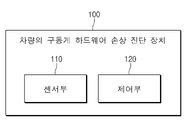
도 1은 본 발명의 일 실시 예에 따른 차량의 구동계 하드웨어 손상 진단 장치를 나타내는 블록도이다.
도 2는 본 발명의 일 실시 예에 따른 EV AWD(Electric Vehicle All Wheel Drive) 차량의 구동계를 나타내는 블록도이다.
도 3은 본 발명의 일 실시 예에 따른 디스커넥터를 나타내는 도면이다.
도 4는 본 발명의 일 실시 예에 따른 디스커넥터의 체결 정도를 나타내는 도면이다.
도 5는 본 발명의 일 실시 예에 따른 모터 속도 및 모터 토크를 나타낸 그래프이다.
도 6은 본 발명의 일 실시 예에 따른 차량의 구동계 하드웨어 손상 진단 장치가 구동계 하드웨어의 손상을 진단하는 과정을 나타내는 흐름도이다.
도 7은 본 발명의 다른 일 실시 예에 따른 차량의 구동계 하드웨어 손상 진단 방법을 나타내는 흐름도이다.1 is a block diagram illustrating an apparatus for diagnosing damage to a drive system hardware of a vehicle according to an embodiment of the present invention.
2 is a block diagram illustrating a drive system of an EV AWD (Electric Vehicle All Wheel Drive) vehicle according to an embodiment of the present invention.
3 is a diagram illustrating a disconnector according to an embodiment of the present invention.
4 is a diagram illustrating a degree of fastening of a disconnector according to an embodiment of the present invention.
5 is a graph illustrating a motor speed and a motor torque according to an embodiment of the present invention.
6 is a flowchart illustrating a process of diagnosing damage to driveline hardware by an apparatus for diagnosing driveline hardware damage of a vehicle according to an embodiment of the present invention.
7 is a flowchart illustrating a method for diagnosing damage to a drive system hardware of a vehicle according to another embodiment of the present invention.
이하, 본 발명의 일부 실시 예들을 예시적인 도면을 통해 상세하게 설명한다. 각 도면의 구성요소들에 참조 부호를 부가함에 있어서, 동일한 구성요소들에 대해서는 비록 다른 도면 상에 표시되더라도 가능한 한 동일한 부호를 가지도록 하고 있음에 유의해야 한다. 또한, 본 발명의 실시 예를 설명함에 있어, 관련된 공지 구성 또는 기능에 대한 구체적인 설명이 본 발명의 실시 예에 대한 이해를 방해한다고 판단되는 경우에는 그 상세한 설명은 생략한다.Hereinafter, some embodiments of the present invention will be described in detail with reference to exemplary drawings. In adding reference numerals to the components of each drawing, it should be noted that the same components are given the same reference numerals as much as possible even though they are indicated on different drawings. In addition, in describing the embodiment of the present invention, if it is determined that a detailed description of a related known configuration or function interferes with the understanding of the embodiment of the present invention, the detailed description thereof will be omitted.
본 발명의 실시 예의 구성 요소를 설명하는 데 있어서, 제 1, 제 2, A, B, (a), (b) 등의 용어를 사용할 수 있다. 이러한 용어는 그 구성 요소를 다른 구성 요소와 구별하기 위한 것일 뿐, 그 용어에 의해 해당 구성 요소의 본질이나 차례 또는 순서 등이 한정되지 않는다. 또한, 다르게 정의되지 않는 한, 기술적이거나 과학적인 용어를 포함해서 여기서 사용되는 모든 용어들은 본 발명이 속하는 기술 분야에서 통상의 지식을 가진 자에 의해 일반적으로 이해되는 것과 동일한 의미를 가진다. 일반적으로 사용되는 사전에 정의되어 있는 것과 같은 용어들은 관련 기술의 문맥상 가지는 의미와 일치하는 의미를 가진 것으로 해석되어야 하며, 본 출원에서 명백하게 정의하지 않는 한, 이상적이거나 과도하게 형식적인 의미로 해석되지 않는다.In describing the components of the embodiment of the present invention, terms such as first, second, A, B, (a), (b), etc. may be used. These terms are only for distinguishing the elements from other elements, and the essence, order, or order of the elements are not limited by the terms. In addition, unless otherwise defined, all terms used herein, including technical or scientific terms, have the same meaning as commonly understood by one of ordinary skill in the art to which this invention belongs. Terms such as those defined in commonly used dictionaries should be interpreted as having a meaning consistent with the meaning in the context of the related art, and should not be interpreted in an ideal or excessively formal meaning unless explicitly defined in the present application. does not
이하, 도 1 내지 도 7을 참조하여, 본 발명의 실시 예들을 구체적으로 설명하기로 한다.Hereinafter, embodiments of the present invention will be described in detail with reference to FIGS. 1 to 7 .
도 1은 본 발명의 일 실시 예에 따른 차량의 구동계 하드웨어 손상 진단 장치를 나타내는 블록도이다.1 is a block diagram illustrating an apparatus for diagnosing damage to a drive system hardware of a vehicle according to an embodiment of the present invention.
도 1을 참조하면, 차량의 구동계 하드웨어 손상 진단 장치(100)는 센서부(110) 및 제어부(120)를 포함할 수 있다.Referring to FIG. 1 , an
본 발명에 따른 차량의 구동계 하드웨어 손상 진단 장치(100)는 차량의 내부 또는 외부에 구현될 수 있다. 이때, 차량의 구동계 하드웨어 손상 진단 장치(100)는 차량의 내부 제어 유닛들과 일체로 형성될 수 있으며, 별도의 하드웨어 장치로 구현되어 연결 수단에 의해 차량의 제어 유닛들과 연결될 수도 있다.The
일 예로, 차량의 구동계 하드웨어 손상 진단 장치(100)는 차량과 일체로 구현될 수도 있고, 차량과 별개의 구성으로 차량에 설치/부착되는 형태로 구현될 수도 있고, 또는 일부는 차량과 일체로 구현되고, 다른 일부는 차량과 별개의 구성으로 차량에 설치/부착되는 형태로 구현될 수도 있다.As an example, the
센서부(110)는 차량의 보조 구동륜의 모터 속도 및 차량의 주 구동륜의 모터 속도를 획득할 수 있다.The
센서부(110)는 디스커넥터의 슬리브의 위치, 포크의 위치 및 디스커넥터를 제어하는 모터의 전류 중 적어도 하나 이상을 획득할 수 있다.The
일 예로, 센서부(110)는 휠 속 센서, 위치 센서, 전류 센서 등을 포함할 수 있다.For example, the
다른 일 예로, 센서부(110)는 차량의 모터 시스템 또는 DAS(Discunnector Assist System)와 연결되어, 차량의 모터 시스템 또는 DAS로부터 차량의 보조 구동륜의 모터 속도, 차량의 주 구동륜의 모터 속도, 디스커넥터의 슬리브의 위치, 포크의 위치 및 디스커넥터를 제어하는 모터의 전류 중 적어도 하나 이상에 대한 정보를 전달받을 수 있다.As another example, the
또한, 센서부(110)는 제어부(120)와 무선 또는 유선 통신을 통해 연결되어, 직접 또는 간접적으로 차량의 보조 구동륜의 모터 속도, 차량의 주 구동륜의 모터 속도, 디스커넥터의 슬리브의 위치, 포크의 위치 및 디스커넥터를 제어하는 모터의 전류 중 적어도 하나 이상에 대한 정보를 송신할 수 있다.In addition, the
제어부(120)는 각 구성요소들이 제 기능을 정상적으로 수행할 수 있도록 전반적인 제어를 수행할 수 있다. 이러한 제어부(120)는 하드웨어의 형태로 구현되거나, 소프트웨어의 형태로 구현되거나, 또는 하드웨어 및 소프트웨어가 결합된 형태로 구현될 수 있다. 바람직하게는, 제어부(120)는 마이크로프로세서로 구현될 수 있으나 이에 한정되는 것은 아니다. 또한, 제어부(120)는 후술하는 다양한 데이터 처리 및 계산 등을 수행할 수 있다.The
제어부(120)는 보조 구동륜의 모터 속도와 주 구동륜의 모터 속도의 차이가 임계치를 초과하는지 여부를 기반으로, 보조 구동륜의 모터 측 구동계 하드웨어와 보조 구동륜 측 구동계 하드웨어 간의 체결 또는 해제를 통해 동력 전달의 차단 여부를 제어하는 디스커넥터를 포함하는 구동계 하드웨어의 손상 여부를 판단할 수 있다.Based on whether the difference between the motor speed of the auxiliary drive wheel and the motor speed of the main drive wheel exceeds a threshold value, the
디스커넥터는 EV AWD(Electric Vehicle All Wheel Drive) 차량의 보조 구동륜의 모터 측 구동계 하드웨어와 보조 구동륜 측 구동계 하드웨어 간의 체결 또는 해제를 통해 동력 전달의 차단 여부를 제어할 수 있다.The disconnector may control whether power transmission is blocked by engaging or disengaging between the drive system hardware on the motor side of the auxiliary drive wheel of the EV AWD (Electric Vehicle All Wheel Drive) vehicle and the drive system hardware on the auxiliary drive wheel side.
디스커넥터의 구체적인 구조는 추후에 도 3을 통해 설명하기로 한다.A detailed structure of the disconnector will be described later with reference to FIG. 3 .
디스커넥터가 체결된 상태에서, 전륜과 후륜의 휠 속도가 동일해야 하므로, 모터 속도 또한 동일해야 할 수 있다. 하지만 토크 수준에 따라서, 슬립 정도가 일부 상이할 수도 있으므로, 제어부(120)는 보조 구동륜의 모터 속도와 주 구동륜의 모터 속도의 차이가 0을 초과하는지 여부가 아닌 기 설정된 임계치를 초과하는지 여부를 판단하여, 이를 기반으로 구동계 하드웨어의 손상 여부를 판단할 수 있다.In a state in which the disconnector is fastened, since the wheel speed of the front wheel and the rear wheel should be the same, the motor speed may also have to be the same. However, since the degree of slip may be partially different depending on the torque level, the
차량의 구동계 하드웨어에 손상이 존재하여 동력 전달에 문제가 생기는 경우, 휠의 마찰에 의한 부하가 줄거나 사라져 주 구동륜과 보조 구동륜 중 구동계 하드웨어에 손상이 있는 쪽의 모터의 속도가 발산할 수 있다. 따라서, 제어부(120)는 보조 구동륜의 모터 속도와 주 구동륜의 모터 속도의 차이를 통해, 구동계 하드웨어의 손상 여부를 판단할 수 있다.If there is a problem in power transmission due to damage to the vehicle's driveline hardware, the load caused by friction on the wheels is reduced or disappeared, and the speed of the motor of the main drive wheel and the auxiliary drive wheel with damage to the drive line hardware may diverge. Accordingly, the
일 예로, 차량의 구동계 하드웨어 손상 진단 장치(100)는 모터 토크의 적산량과 주 구동륜과 보조 구동륜의 모터 속도 차이의 적산량을 비교하여, 구동계 하드웨어에 손상을 판단할 수 있다.For example, the
제어부(120)는 디스커넥터의 슬리브의 위치, 포크의 위치 및 디스커넥터를 제어하는 모터의 전류 중 적어도 하나 이상을 기반으로, 디스커넥터를 제어하는 시스템의 고장을 판단하고, 디스커넥터를 제어하는 시스템의 고장으로 판단되는 경우, 구동계 하드웨어는 손상이 아닌 것으로 판단할 수 있다.The
일 예로, 제어부(120)는 DAS의 고장과 구동계 하드웨어의 손상을 구분하여, 각각의 경우에 상이한 조치를 취할 수 있으므로, 디스커넥터의 슬리브의 위치, 포크의 위치 및 디스커넥터를 제어하는 모터의 전류 중 적어도 하나 이상을 기반으로, DAS의 고장을 판단할 수 있다.As an example, the
제어부(120)는 디스커넥터의 슬리브의 위치, 포크의 위치 및 디스커넥터를 제어하는 모터의 전류 중 적어도 하나 이상이 특정 범위에 포함되는지 여부를 기반으로, 디스커넥터를 제어하는 시스템의 고장을 판단할 수 있다. 여기서, 특정 범위는, 디스커넥터의 체결 정도에 따라 정해질 수 있다.The
일 예로, 디스커넥터를 제어하는 모터에 의해 슬리브의 위치 또는 포크의 위치가 조절될 수 있다.For example, the position of the sleeve or the position of the fork may be adjusted by a motor controlling the disconnector.
일 예로, 디스커넥터는 슬리브의 위치 또는 포크의 위치에 따라서 보조 구동륜의 모터 측 구동계 하드웨어와 보조 구동륜 측 구동계 하드웨어 간의 체결의 정도를 조절할 수 있다. 이에 대한 구체적인 설명은 추후에 도 3을 통해 하기로 한다.For example, the disconnector may adjust the degree of coupling between the motor-side driveline hardware of the auxiliary drive wheel and the auxiliary drive wheel-side driveline hardware according to the position of the sleeve or the position of the fork. A detailed description thereof will be given later with reference to FIG. 3 .
일 예로, 디스커넥터의 체결 정도에 따라서, 정상으로 판단되는 슬리브의 위치 또는 포크의 위치의 범위가 정해질 수 있다.For example, a range of a position of a sleeve or a position of a fork determined to be normal may be determined according to a fastening degree of the disconnector.
또한, 디스커넥터의 체결 정도에 따라서, 정상으로 판단되는 디스커넥터를 제어하는 모터의 전류의 범위가 정해질 수 있다.Also, the range of the current of the motor that controls the disconnector that is determined to be normal may be determined according to the degree of fastening of the disconnector.
슬리브의 위치 또는 포크의 위치와 디스커넥터의 체결 정도의 관계에 대해서는 추후에 도 4를 통해 설명하기로 한다.The relationship between the position of the sleeve or the position of the fork and the degree of coupling of the disconnector will be described later with reference to FIG. 4 .
제어부(120)는 보조 구동륜의 모터 속도 및 주 구동륜의 모터 속도 중 적어도 하나 이상과 기준 모터 속도를 비교하여, 보조 구동륜의 모터에서 보조 구동륜으로 동력을 전달하는 구동계 하드웨어 및 주 구동륜의 모터에서 주 구동륜으로 동력을 전달하는 구동계 하드웨어 중 적어도 하나 이상의 손상 여부를 판단할 수 있다.The
일 예로, 제어부(120)는 최종적인 구동계 하드웨어의 손상을 판단하기 위해, 기준 모터 속도(모델 속도)와 센서부(110)를 통해 획득한 모터 속도를 비교할 수 있다.For example, the
여기서, 기준 모터 속도는, 차량의 가속도 및 휠 속도 중 적어도 하나 이상을 기반으로 정해질 수 있다.Here, the reference motor speed may be determined based on at least one of vehicle acceleration and wheel speed.
일 예로, 기준 모터 속도는, 모터 토크 및 모터 속도 중 적어도 하나 이상에 의해 계산된 차량의 가속도 및 휠 속도 중 적어도 하나 이상을 기반으로 정해질 수 있다.For example, the reference motor speed may be determined based on at least one of an acceleration of a vehicle and a wheel speed calculated by at least one of a motor torque and a motor speed.
구동계 하드웨어에 손상이 있어 동력 전달에 문제가 생기는 경우, 휠의 마찰에 의한 부하가 줄거나 사라져 모터의 속도가 발산하여 실제 모터 속도가 기준 모터 속도를 초과할 수 있다.If there is a problem in power transmission due to damage to the driveline hardware, the load caused by friction on the wheels will decrease or disappear, causing the speed of the motor to diverge and the actual motor speed may exceed the reference motor speed.
따라서, 제어부(120)는 기준 모터 속도(모델 속도)와 센서부(110)를 통해 획득한 모터 속도를 비교하여 구동계 하드웨어의 손상 여부를 판단할 수 있고, 주 구동륜에 동력을 전달하는 구동계 하드웨어와 보조 구동륜에 동력을 전달하는 구동계 하드웨어 중 구동계 하드웨어의 어떤 부분에 손상이 존재하는지를 판단할 수 있다.Therefore, the
제어부(120)는 보조 구동륜의 모터 속도의 변화량을 적산한 값 및 주 구동륜의 모터 속도의 변화량을 적산한 값 중 적어도 하나 이상과 기준 모터 속도의 변화량을 적산한 값을 비교하여, 보조 구동륜의 모터에서 보조 구동륜으로 동력을 전달하는 구동계 하드웨어 및 주 구동륜의 모터에서 주 구동륜으로 동력을 전달하는 구동계 하드웨어 중 적어도 하나 이상의 손상 여부를 판단할 수 있다.The
일 예로, 제어부(120)는 순간적인 오류값으로 인한 구동계 하드웨어의 손상의 오진단을 방지하기 위해, 기준 모터 속도와 센서부(110)를 통해 획득한 모터 속도 각각의 변화량을 적산한 값을 비교하여, 구동계 하드웨어의 손상 여부를 판단할 수 있다.For example, the
제어부(120)는 보조 구동륜의 모터에서 보조 구동륜으로 동력을 전달하는 구동계 하드웨어가 손상된 것으로 판단된 경우, 디스커넥터를 보조 구동륜에 동력이 전달되지 않는 상태로 제어하고, 주 구동륜의 모터에서 주 구동륜으로 동력을 전달하는 구동계 하드웨어가 손상된 것으로 판단된 경우, 디스커넥터를 보조 구동륜에 동력이 전달되는 상태로 제어할 수 있다.When it is determined that the drive system hardware that transmits power from the motor of the auxiliary drive wheel to the auxiliary drive wheel is damaged, the
일 예로, 제어부(120)는 보조 구동륜의 모터에서 보조 구동륜으로 동력을 전달하는 구동계 하드웨어가 손상된 것으로 판단된 경우, 디스커넥터를 보조 구동륜에 동력이 전달되지 않는 체결 해제 상태로 제어할 수 있다.For example, when it is determined that the drive system hardware that transmits power from the motor of the auxiliary drive wheel to the auxiliary drive wheel is damaged, the
그러면, 차량은 주 구동륜의 모터로부터 주 구동륜으로 동력이 전달되어 2WD(Two Wheel Drive) 상태로 주행할 수 있고, 보조 구동륜 측의 구동계 하드웨어가 손상된 상태에서도 안전하게 주행할 수 있다.Then, power is transmitted from the motor of the main driving wheel to the main driving wheel, so that the vehicle can be driven in a two wheel drive (2WD) state, and can be safely driven even in a state in which the drive system hardware on the auxiliary driving wheel side is damaged.
일 예로, 제어부(120)는 주 구동륜의 모터에서 주 구동륜으로 동력을 전달하는 구동계 하드웨어가 손상된 것으로 판단된 경우, 디스커넥터를 보조 구동륜에 동력이 전달되는 체결 상태로 제어할 수 있다.For example, when it is determined that the drive system hardware that transmits power from the motor of the main driving wheel to the main driving wheel is damaged, the
그러면, 차량은 보조 구동륜의 모터로부터 보조 구동륜으로 동력이 전달되어 주행할 수 있고, 주 구동륜 측의 구동계 하드웨어가 손상된 상태에서도 안전하게 주행할 수 있다.Then, the vehicle can be driven by transmitting power from the motor of the auxiliary driving wheel to the auxiliary driving wheel, and can be safely driven even in a state in which the drive system hardware on the main driving wheel side is damaged.
제어부(120)는 디스커넥터를 제어하는 시스템의 고장으로 판단된 경우, 디스커넥터의 작동을 제한할 수 있다.When it is determined that the system for controlling the disconnector has failed, the
일 예로, 제어부(120)는 디스커넥터를 제어하는 시스템의 고장으로 판단된 경우, 디스커넥터의 작동을 제한하여, 고장으로 판단된 디스커넥터의 작동으로 인한 사고를 방지할 수 있다.For example, when it is determined that the system for controlling the disconnector has failed, the
제어부(120)는 구동계 하드웨어가 손상된 것으로 판단된 경우, 차량의 운전자가 요구하는 토크의 반영을 제한할 수 있다.When it is determined that the drive system hardware is damaged, the
구동계 하드웨어가 손상된 경우, 주 구동륜과 보조 구동륜 중 구동계 하드웨어가 손상되지 않은 쪽의 모터를 통해 동력을 전달하여 차량을 주행하는 시스템을 구현하는 본 발명에 의하면, 정상 상태보다 작은 파워 또는 토크가 반영될 수 있다.According to the present invention, which implements a system for driving a vehicle by transmitting power through the motor of the undamaged side of the drive system hardware among the main driving wheel and the auxiliary driving wheel when the drive system hardware is damaged, power or torque smaller than the normal state may be reflected. can
따라서, 제어부(120)는 구동계 하드웨어가 손상된 것으로 판단된 경우, 차량의 운전자가 요구하는 토크의 반영을 제한하고, 주 구동륜과 보조 구동륜 중 구동계 하드웨어가 손상되지 않은 쪽의 모터를 통해 동력을 전달하여 차량을 주행하도록 제어할 수 있다.Therefore, when it is determined that the drive system hardware is damaged, the
제어부(120)는 보조 구동륜의 모터에서 보조 구동륜으로 동력을 전달하는 구동계 하드웨어가 손상된 것으로 판단된 경우, 보조 구동륜의 파워 및 토크 중 적어도 하나 이상을 제한하고, 주 구동륜의 모터에서 주 구동륜으로 동력을 전달하는 구동계 하드웨어가 손상된 것으로 판단된 경우, 주 구동륜의 파워 및 토크 중 적어도 하나 이상을 제한할 수 있다.When it is determined that the drive system hardware that transmits power from the motor of the auxiliary drive wheel to the auxiliary drive wheel is damaged, the
구동계 하드웨어에 손상이 있는 경우, 모터로부터 휠까지 동력이 전달되지 않을 수 있다. 이에 따라, 모터에는 휠의 마찰에 의한 부하가 줄어들거나 또는 사라질 수 있어, 이러한 경우에 모터의 속도가 발산하여 큰 고장 또는 사고를 유발할 수 있다.If the driveline hardware is damaged, power may not be transmitted from the motor to the wheels. Accordingly, the load due to friction of the wheel may be reduced or disappear on the motor, and in this case, the speed of the motor may be diverged, which may cause a major failure or accident.
또한, 구동계 하드웨어에 손상이 있는 경우, 반대쪽 고마찰 측 휠에서는 시스템이 휠 스핀 상황으로 인지하여 브레이크 제어기가 오작동하고, 큰 사고로 이어질 수도 있다. 이때, 강한 충격에 의해 기타 부품에 물리적인 충격이 동반되며, 모터의 발산으로 전장 부품의 고장도 발생할 수 있다.In addition, if there is damage to the drive system hardware, the system recognizes a wheel spin situation on the opposite high-friction side wheel, and the brake controller malfunctions, which may lead to a serious accident. At this time, the strong impact accompanies the physical impact to other parts, and the dissipation of the motor may cause a breakdown of the electrical components.
따라서, 제어부(120)는 손상이 진단된 구동계 하드웨어에 해당하는 구동륜 측의 모터의 파워 및 토크 중 적어도 하나 이상을 제한하여, 모터의 속도가 발산하여 큰 고장 또는 사고를 방지할 수 있다.Accordingly, the
제어부(120)는 주 구동륜의 모터에서 주 구동륜으로 동력을 전달하는 구동계 하드웨어가 손상된 것으로 판단된 경우, 경고등을 통해 사용자에게 보조 구동륜의 모터를 통해 주행한다는 내용의 알림을 제공할 수 있다.When it is determined that the drive system hardware that transmits power from the motor of the main drive wheel to the main drive wheel is damaged, the
일 예로, 제어부(120)는 차량의 클러스터(Cluster), HUD(Head-Up Display), AVN(Audio, Video, Navigation) 등에 표시되는 경고등을 통해, 사용자에게 보조 구동륜의 모터를 통해 주행한다는 내용의 알림을 제공할 수 있다.For example, the
일 예로, 표시되는 경고등은 보조 구동륜 또는 구동계 하드웨어에 문제가 있음을 직관적으로 알릴 수 있는 심볼의 경고등을 포함할 수 있다.As an example, the displayed warning light may include a symbol warning light that can intuitively inform that there is a problem with the auxiliary drive wheel or drive system hardware.
제어부(120)는 보조 구동륜의 모터에서 보조 구동륜으로 동력을 전달하는 구동계 하드웨어가 손상된 것으로 판단된 경우, 디스커넥터를 보조 구동륜에 동력이 전달되는 상태로 제어하며, 보조 구동륜의 모터에 토크를 인가하여, 구동계 하드웨어의 손상 여부를 재판단하고, 구동계 하드웨어의 손상된 것으로 재판단된 경우, 고장모드에 진입할 수 있다.When it is determined that the drive system hardware that transmits power from the motor of the auxiliary drive wheel to the auxiliary drive wheel is damaged, the
일 예로, 제어부(120)는 디스커넥터의 체결을 통해, 보조 구동륜에 동력이 전달되는 상태로 제어를 시도한 후, 보조 구동륜의 모터에 약한 토크를 인가하여 보조 구동륜의 모터 속도가 발산하는지 여부를 확인할 수 있다. 이를 통해, 제어부(120)는 보조 구동륜 측의 구동계 하드웨어의 손상을 재판단한 후, 손상된 것으로 재판단되는 경우, 고장모드로 진입하여, 구동계를 제어할 수 있다.For example, the
보조 구동륜의 모터에 약한 토크를 인가하는 이유는, 보조 구동륜의 모터에 강한 토크를 인가할 경우, 만약 구동계 하드웨어에 손상이 있다면 모터의 속도가 발산하고 큰 사고 또는 고장을 유발할 수 있기 때문이다.The reason for applying a weak torque to the motor of the auxiliary drive wheel is that when a strong torque is applied to the motor of the auxiliary drive wheel, if the drive system hardware is damaged, the speed of the motor may diverge and cause a major accident or failure.
일 예로, 고장모드는 제한된 출력의 운행을 제공하는 림프홈 모드(Limp Home Mode)를 포함할 수 있다.For example, the failure mode may include a limp home mode that provides operation of a limited output.
도 2는 본 발명의 일 실시 예에 따른 EV AWD(Electric Vehicle All Wheel Drive) 차량의 구동계를 나타내는 블록도이다.2 is a block diagram illustrating a drive system of an EV AWD (Electric Vehicle All Wheel Drive) vehicle according to an embodiment of the present invention.
도 2를 참조하면, 본 발명의 일 실시 예에 따른 EV AWD 차량의 구동계는 주 구동륜(201), 보조 구동륜(202), 디스커넥터(203), 주 구동륜의 모터(204) 및 보조 구동륜의 모터(205)를 포함할 수 있다.Referring to FIG. 2 , the driving system of an EV AWD vehicle according to an embodiment of the present invention includes a
일 예로, 주 구동륜(201)은 전륜 또는 후륜일 수 있고, 보조 구동륜(202)는 전륜 또는 후륜 중 주 구동륜(201)이 아닌 것일 수 있다.For example, the
디스커넥터(203)는 체결 또는 해제되어, 보조 구동륜(202) 측의 하드웨어와 보조 구동륜의 모터(205) 측의 하드웨어를 동력이 전달되는 상태로 연결하거나 또는 분리된 상태로 제어할 수 있다.The
디스커넥터(203)가 체결되는 경우, 보조 구동륜의 모터(205)와 보조 구동륜(202)이 기계적으로 연결되어 상호간에 동력 또는 마찰에 의한 부하가 전달될 수 있고, 디스커넥터(203)가 해제되는 경우, 보조 구동륜의 모터(205)와 보조 구동륜(202)이 기계적으로 분리되어 상호간에 동력 또는 마찰에 의한 부하가 전달되지 않을 수 있다.When the
EV AWD 차량은 디스커넥터(203)의 체결 또는 해제에 따라 2WD 또는 4WD(Four Wheel Drive)로 주행할 수 있고, 디스커넥터 시스템을 통해, 차량의 연비를 개선하거나, 필요에 따라서 파워 또는 토크를 보조 구동륜의 모터(205)를 통해 보조할 수 있다.The EV AWD vehicle can drive in 2WD or 4WD (Four Wheel Drive) according to the connection or release of the
디스커넥터(203)의 구조에 대해서는 도 3을 통해 구체적으로 설명하기로 한다.The structure of the
도 3은 본 발명의 일 실시 예에 따른 디스커넥터를 나타내는 도면이다.3 is a diagram illustrating a disconnector according to an embodiment of the present invention.
도 3을 참조하면, 본 발명의 일 실시 예에 따른 디스커넥터는 DAS 제어용 모터(301), 포크(302), 슬리브(303), 샤프트(304) 및 허브(305)를 포함할 수 있다.Referring to FIG. 3 , the disconnector according to an embodiment of the present invention may include a
DAS 제어용 모터(301)는 DAS 제어용 모터(301)에 흐르는 전류의 조절을 통해, 포크(302)를 전진 또는 후진하도록 포크(302)의 위치를 제어할 수 있다.The
포크(302)는 슬리브(303)와 기계적으로 연결되어, 포크(302)가 전진 또는 후진하는 경우, 슬리브(303)도 전진 또는 후진할 수 있다.The
슬리브(303)의 전진 또는 후진을 통해, 샤프트(304) 부분과 허브(305) 부분이 체결 또는 해제될 수 있고, 샤프트(304) 부분과 허브(305) 부분이 체결되는 경우, 디스커넥터는 보조 구동륜의 모터와 보조 구동륜 사이의 동력이 전달되는 연결된 상태일 수 있고, 샤프트(304) 부분과 허브(305) 부분이 체결이 해제되는 경우, 디스커넥터는 보조 구동륜의 모터와 보조 구동륜 사이의 동력이 전달되지 않는 분리된 상태일 수 있다.Through the forward or backward movement of the
DAS 스트로크는 디스커넥터의 슬리브의 위치 또는 포크의 위치로 정의될 수 있다.The DAS stroke can be defined as the position of the sleeve or the position of the fork of the disconnector.
도 4는 본 발명의 일 실시 예에 따른 디스커넥터의 체결 정도를 나타내는 도면이다.4 is a diagram illustrating a degree of fastening of a disconnector according to an embodiment of the present invention.
도 4를 참조하면, 특정 위치를 기준으로 디스커넥터가 체결 또는 해제되는 방향으로의 DAS 스트로크(디스커넥터의 슬리브의 위치 또는 포크의 위치)의 값에 따라서 디스커넥터의 체결 정도의 상태가 정해질 수 있다.Referring to FIG. 4 , the state of the degree of fastening of the disconnector can be determined according to the value of the DAS stroke (the position of the sleeve or the fork of the disconnector) in the direction in which the disconnector is fastened or released based on a specific position. have.
일 예로, 특정 위치를 기준으로 DAS 스트로크가 7.0mm~8.3mm의 범위에 포함되는 경우, 디스커넥터의 체결 정도의 상태는 “Approaching 상태”(401)로 정해질 수 있다.For example, when the DAS stroke is included in the range of 7.0 mm to 8.3 mm based on a specific position, the state of the degree of fastening of the disconnector may be determined as the “approaching state” 401 .
일 예로, 특정 위치를 기준으로 DAS 스트로크가 8.3mm~9.7mm의 범위에 포함되는 경우, 디스커넥터의 체결 정도의 상태는 “Meeting 상태”(402)로 정해질 수 있다.For example, when the DAS stroke is included in the range of 8.3 mm to 9.7 mm based on the specific position, the state of the degree of coupling of the disconnector may be determined as the “meeting state” 402 .
일 예로, 특정 위치를 기준으로 DAS 스트로크가 9.7mm~11.6mm의 범위에 포함되는 경우, 디스커넥터의 체결 정도의 상태는 “Pushing 상태”(403)로 정해질 수 있다.For example, when the DAS stroke is included in the range of 9.7 mm to 11.6 mm based on a specific position, the state of the degree of fastening of the disconnector may be determined as the “Pushing state” 403 .
일 예로, 특정 위치를 기준으로 DAS 스트로크가 11.6mm~12.4mm의 범위에 포함되는 경우, 디스커넥터의 체결 정도의 상태는 “Park 상태”(404)로 정해질 수 있다.For example, when the DAS stroke is included in the range of 11.6 mm to 12.4 mm based on a specific position, the state of the degree of fastening of the disconnector may be determined as the “Park state” 404 .
여기서, 각각의 디스커넥터의 체결 정도의 상태의 경계값을 나타낸 수치들은 예시를 들기 위한 값이며, 실제로는 다른 값으로 정해질 수도 있다.Here, the numerical values indicating the boundary value of the state of the fastening degree of each disconnector are for example only, and may actually be set to another value.
또한, DAS 스토로크의 값에 따라 변하는 각각의 디스커넥터의 체결 정도의 상태가 각각의 단계에서 다음 단계로 변화하는 것을 판단하기 위한, “passApproaching 상태”(405), “passMeeting 상태”(406), “passPush 상태”(407)가 존재할 수 있다.In addition, for determining that the state of the degree of fastening of each disconnector that changes according to the value of the DAS stroke changes from each stage to the next stage, "passApproaching state" 405, "passMeeting state" 406, A “passPush state” 407 may exist.
디스커넥터의 체결 정도의 상태가 “passApproaching 상태”(405), “passMeeting 상태”(406) 또는 “passPush 상태”(407)인지 여부는 경계값인 8.3mm, 9.7mm, 11.6mm를 기준으로 한 특정 범위에 DAS 스트로크의 값이 포함되는지 여부에 따라서 정해질 수 있고, 경계값을 기준으로 한 특정 범위는 “Approaching 상태”(401), “Meeting 상태”(402), “Pushing 상태”(403), “Park 상태”(404)에 해당하는 특정 범위에 비해 작은 값을 가질 수 있다.Whether the connection degree of the disconnector is “passApproaching state” (405), “passMeeting state” (406), or “passPush state” (407) is specific based on the boundary values of 8.3mm, 9.7mm, and 11.6mm. It can be determined depending on whether the range includes the value of the DAS stroke, and a specific range based on the boundary value is “Approaching state” (401), “Meeting state” (402), “Pushing state” (403), It may have a small value compared to a specific range corresponding to the “Park state” 404 .
“Approaching 상태”(401), “Meeting 상태”(402), “Pushing 상태”(403), “Park 상태”(404), “passApproaching 상태”(405), “passMeeting 상태”(406), “passPush 상태”(407)에 해당하는 각각의 디스커넥터의 체결 정도의 상태에 따라서, 정상 범위로 판단되는 디스커넥터의 슬리브의 위치 또는 포크의 위치와 디스커넥터를 제어하는 모터의 전류의 범위가 정해질 수 있다.“Approaching Status” (401), “Meeting Status” (402), “Pushing Status” (403), “Park Status” (404), “passApproaching Status” (405), “passMeeting Status” (406), “passPush” According to the state of the fastening degree of each disconnector corresponding to the “state” 407, the position of the sleeve or fork of the disconnector that is judged to be in the normal range, and the range of the current of the motor controlling the disconnector can be determined. have.
각각의 상태에 따라, 요구되는 모터의 속도가 다르고, 모터에 걸리는 부하(물리적인 저항)가 상이하기 때문에, 정상 범위로 판단되는 디스커넥터의 슬리브의 위치 또는 포크의 위치와 디스커넥터를 제어하는 모터의 전류의 범위가 상이하게 정해질 수 있다.According to each state, the required motor speed is different and the load (physical resistance) applied to the motor is different, so the position of the sleeve or fork of the disconnector and the position of the disconnector are determined to be within the normal range. The range of the current of may be set differently.
일 예로, 차량의 구동계 하드웨어 손상 진단 장치(100)는 “Meeting 상태”(402)에서는 디스커넥터를 제어하는 모터의 전류가 5~15A의 범위에 포함될 경우 DAS에 고장이 없는 정상 상태로 판단할 수 있다.As an example, the vehicle drive system hardware
여기서, 5~10A라는 수치는 예시를 들기 위해 임의로 설정된 값이며, 실제로는 다른 값으로 설정될 수도 있다. Here, the numerical value of 5 to 10A is an arbitrarily set value for the sake of illustration, and may actually be set to another value.
도 5는 본 발명의 일 실시 예에 따른 모터 속도 및 모터 토크를 나타낸 그래프이다.5 is a graph illustrating a motor speed and a motor torque according to an embodiment of the present invention.
도 5의 그래프는 시간에 따른 전륜 모터 속도(501), 후륜 모터 속도(502), 전륜 모터 속도의 변화량을 기반으로 산출된 전륜 모터 토크(503) 및 실제 측정된 전륜 모터 토크(504)의 그래프를 나타낸 것일 수 있다.The graph of FIG. 5 is a graph of the front-
디스커넥터 시스템의 제어로 인해 2WD에서 4WD로 주행 모드 전환이 이루어진 경우, 구동계 하드웨어에 손상이 없는 정상적인 상황에서는 전륜의 모터 속도와 후륜의 모터 속도가 동일해야한다.If the driving mode is switched from 2WD to 4WD due to the control of the Disconnector system, the motor speed of the front wheel and the motor speed of the rear wheel should be the same under normal conditions without damage to the drive system hardware.
하지만, 구동계 하드웨어에 손상이 있는 경우에, 전륜의 모터와 후륜의 모터 중 구동계 하드웨어에 손상이 있는 쪽의 모터는 휠의 마찰에 의한 부하를 받지 않으므로, 모터 속도가 발산할 수 있다.However, when the drive system hardware is damaged, the motor of the front wheel motor and the rear wheel motor with damage to the drive system hardware does not receive a load due to the friction of the wheel, and thus the motor speed may diverge.
전륜 모터 속도(501)와 후륜 모터 속도(502)의 속도 차이가 크게 나고 있는 상태이므로, 차량의 구동계 하드웨어 손상 진단 장치(100)는 전륜 쪽의 구동계 하드웨어에 손상이 있는 것으로 판단할 수 있다.Since the speed difference between the front
또한, 구동계 하드웨어에 손상이 없는 정상적인 상황에서 전륜 모터 속도의 변화량을 기반으로 산출된 전륜 모터 토크(503)와 실제 측정된 전륜 모터 토크(504)는 동일하거나 허용 가능한 오차 범위 내의 차이가 있을 수 있다.In addition, in a normal situation where there is no damage to the drive system hardware, the front
하지만, 전륜 쪽 구동계 하드웨어에 손상이 있는 경우에, 전륜 쪽의 모터는 휠의 마찰에 의한 부하를 받지 않으므로, 전륜 모터 속도의 변화량을 기반으로 산출된 전륜 모터 토크(503)가 실제 측정된 전륜 모터 토크(504)에 비해 클 수 있어, 이를 통해, 차량의 구동계 하드웨어 손상 진단 장치(100)는 전륜 쪽의 구동계 하드웨어에 손상이 있는 것으로 판단할 수 있다.However, if the front wheel drive system hardware is damaged, the front wheel motor does not receive a load due to the friction of the wheel, so the front
도 6은 본 발명의 일 실시 예에 따른 차량의 구동계 하드웨어 손상 진단 장치가 구동계 하드웨어의 손상을 진단하는 과정을 나타내는 흐름도이다.6 is a flowchart illustrating a process of diagnosing damage to driveline hardware by an apparatus for diagnosing driveline hardware damage of a vehicle according to an embodiment of the present invention.
도 6을 참조하면, 차량의 구동계 하드웨어 손상 진단 장치(100)는 보조 구동륜 모터와 주 구동륜 모터의 속도를 획득할 수 있다(S601).Referring to FIG. 6 , the
일 예로, 차량의 구동계 하드웨어 손상 진단 장치(100)는 휠 속도 센서 등을 통해, 보조 구동륜 모터와 주 구동륜 모터의 속도를 획득할 수 있다.As an example, the
차량의 구동계 하드웨어 손상 진단 장치(100)는 보조 구동륜 모터와 주 구동륜 모터의 속도를 획득한 후(S601), 보조 구동륜 모터 속도와 주 구동륜 모터 속도 차이가 임계치를 초과하는지 여부를 확인할 수 있다(S602).After obtaining the speeds of the auxiliary drive wheel motor and the main drive wheel motor ( S601 ), the
일 예로, 임계치는 보조 구동륜 모터와 주 구동륜 모터의 토크의 차이에 비례하여 설정된 값일 수 있다.For example, the threshold value may be a value set in proportion to a difference in torque between the auxiliary driving wheel motor and the main driving wheel motor.
차량의 구동계 하드웨어 손상 진단 장치(100)는 보조 구동륜 모터 속도와 주 구동륜 모터 속도 차이가 임계치를 초과하는지 여부를 확인한 후(S602), 보조 구동륜 모터 속도와 주 구동륜 모터 속도 차이가 임계치를 초과하지 않는 것으로 확인된 경우, 다시 S601의 과정을 수행할 수 있다.The vehicle drive system hardware
일 예로, 차량의 구동계 하드웨어 손상 진단 장치(100)는 보조 구동륜 모터 속도와 주 구동륜 모터 속도 차이가 임계치를 초과하지 않는 것으로 확인된 경우, 구동계 하드웨어에 손상이 없는 것으로 판단하여, 다시 S601의 과정을 수행할 수 있다.For example, when it is confirmed that the difference between the speed of the auxiliary drive wheel motor and the speed of the main drive wheel motor does not exceed the threshold, the vehicle drive system hardware
차량의 구동계 하드웨어 손상 진단 장치(100)는 보조 구동륜 모터 속도와 주 구동륜 모터 속도 차이가 임계치를 초과하는지 여부를 확인한 후(S602), 보조 구동륜 모터 속도와 주 구동륜 모터 속도 차이가 임계치를 초과하는 것으로 확인된 경우, DAS 스트로크가 특정 범위에 포함되는지 여부를 확인할 수 있다(S603).The vehicle drive system hardware
DAS 스트로크는 디스커넥터의 슬리브의 위치 또는 포크의 위치로 정의될 수 있다.The DAS stroke can be defined as the position of the sleeve or the position of the fork of the disconnector.
일 예로, 차량의 구동계 하드웨어 손상 진단 장치(100)는 보조 구동륜 모터 속도와 주 구동륜 모터 속도 차이가 임계치를 초과하는 것으로 확인된 경우, DAS의 고장을 진단하여, 구동계 하드웨어의 손상과 구별하기 위해, DAS 스트로크가 특정 범위에 포함되는지 여부를 확인할 수 있다.As an example, when it is confirmed that the difference between the speed of the auxiliary drive wheel motor and the main drive wheel motor speed exceeds a threshold, the
일 예로, DAS 스트로크의 정상 범위를 판단하기 위한 특정 범위는 디스커넥터의 체결 정도에 따라 정해질 수 있다.As an example, a specific range for determining the normal range of the DAS stroke may be determined according to a fastening degree of the disconnector.
차량의 구동계 하드웨어 손상 진단 장치(100)는 DAS 스트로크가 특정 범위에 포함되는지 여부를 확인한 후(S603), DAS 스트로크가 특정 범위에 포함되지 않는 것으로 확인된 경우, DAS의 고장으로 판단하고, 디스커넥터의 작동을 제한할 수 있다(S604).After checking whether the DAS stroke is included in the specific range, the vehicle driving system hardware
일 예로, 차량의 구동계 하드웨어 손상 진단 장치(100)는 DAS 스트로크가 특정 범위에 포함되지 않는 것으로 확인된 경우, DAS의 고장으로 판단하여, 구동계 하드웨어의 손상과는 상이한 조치를 취할 수 있다.For example, when it is determined that the DAS stroke is not included in the specific range, the
일 예로, 차량의 구동계 하드웨어 손상 진단 장치(100)는 DAS의 고장으로 판단되면, 드라이브 샤프트나, 베어링, 조인트 등 기타 구동계 하드웨어의 소손이 아닌 것으로 판단할 수 있다.As an example, when it is determined that the DAS is malfunctioning, the
일 예로, 차량의 구동계 하드웨어 손상 진단 장치(100)는 DAS의 고장으로 판단되면, 디스커넥터의 작동을 제한하여, 고장으로 판단된 디스커넥터의 작동으로 인한 사고 또는 다른 고장을 방지할 수 있다.For example, when it is determined that the DAS is malfunctioning, the
차량의 구동계 하드웨어 손상 진단 장치(100)는 DAS 스트로크가 특정 범위에 포함되는지 여부를 확인한 후(S603), DAS 스트로크가 특정 범위에 포함되는 것으로 확인된 경우, DAS 전류가 특정 범위에 포함되는지 여부를 확인할 수 있다(S605).After confirming whether the DAS stroke is included in the specific range (S603), the vehicle driving system hardware
일 예로, DAS 전류의 정상 범위를 판단하기 위한 특정 범위는 디스커넥터의 체결 정도에 따라 정해질 수 있다.For example, a specific range for determining the normal range of the DAS current may be determined according to the degree of fastening of the disconnector.
차량의 구동계 하드웨어 손상 진단 장치(100)는 DAS 전류가 특정 범위에 포함되는지 여부를 확인한 후(S605), DAS 전류가 특정 범위에 포함되지 않는 것으로 확인된 경우, DAS의 고장으로 판단하고, 디스커넥터의 작동을 제한할 수 있다(S604).After confirming whether the DAS current is included in the specific range (S605), the vehicle driveline hardware
일 예로, 차량의 구동계 하드웨어 손상 진단 장치(100)는 DAS 전류가 특정 범위에 포함되지 않는 것으로 확인된 경우, DAS의 고장으로 판단하여, 구동계 하드웨어의 손상과는 상이한 조치를 취할 수 있다.As an example, when it is determined that the DAS current is not included in the specific range, the
차량의 구동계 하드웨어 손상 진단 장치(100)는 DAS 전류가 특정 범위에 포함되는지 여부를 확인한 후(S605), DAS 전류가 특정 범위에 포함되는 것으로 확인된 경우, 보조 구동륜 모터 속도와 주 구동륜 모터 속도의 변화량을 적산한 값과 기준 모터 속도의 변화량을 적산한 값을 비교할 수 있다(S606).After confirming whether the DAS current is included in the specific range ( S605 ), the
일 예로, 차량의 구동계 하드웨어 손상 진단 장치(100)는 순간적인 오류값으로 인한 구동계 하드웨어의 손상의 오진단을 방지하기 위해, 기준 모터 속도와 보조 구동륜 모터 속도 또는 주 구동륜 모터 속도의 변화량을 적산한 값을 비교하여, 구동계 하드웨어의 손상을 판단할 수 있다.For example, in order to prevent erroneous diagnosis of damage to driveline hardware due to an instantaneous error value, the
차량의 구동계 하드웨어 손상 진단 장치(100)는 보조 구동륜 모터 속도와 주 구동륜 모터 속도의 변화량을 적산한 값과 기준 모터 속도의 변화량을 적산한 값을 비교한 후(S606), 기준 모터 속도보다 보조 구동륜 모터 속도가 큰지 여부를 확인할 수 있다(S607).The
일 예로, 차량의 구동계 하드웨어 손상 진단 장치(100)는 기준 모터 속도의 변화량을 적산한 값보다 와 보조 구동륜 모터 속도의 변화량을 적산한 값이 큰지 여부를 확인함으로써, 기준 모터 속도보다 보조 구동륜 모터 속도가 큰지 여부를 확인할 수 있다.As an example, the
차량의 구동계 하드웨어 손상 진단 장치(100)는 기준 모터 속도보다 보조 구동륜 모터 속도가 큰지 여부를 확인한 후(S607), 기준 모터 속도보다 보조 구동륜 모터 속도가 큰 것으로 확인된 경우, 보조 구동륜의 모터에서 보조 구동륜으로 동력을 전달하는 구동계 하드웨어에 손상이 존재하는 것으로 판단할 수 있다(S608).The
일 예로, 차량의 구동계 하드웨어 손상 진단 장치(100)는 기준 모터 속도보다 보조 구동륜 모터 속도가 큰 것으로 확인된 경우, 보조 구동륜 모터에 부하가 걸리지 않아, 모터 속도가 발산하며, 보조 구동륜의 모터에서 보조 구동륜으로 동력을 전달하는 구동계 하드웨어에 손상이 존재하는 것으로 판단할 수 있다.As an example, when it is determined that the vehicle's driveline hardware
차량의 구동계 하드웨어 손상 진단 장치(100)는 보조 구동륜의 모터에서 보조 구동륜으로 동력을 전달하는 구동계 하드웨어에 손상이 존재하는 것으로 판단한 후(S608), 디스커넥터를 해제하고, 운전자가 요구하는 토크의 반영을 제한할 수 있다(S609).After determining that damage exists in the drive system hardware that transmits power from the motor of the auxiliary drive wheel to the auxiliary drive wheel ( S608 ), the
일 예로, 차량의 구동계 하드웨어 손상 진단 장치(100)는 디스커넥터를 해제하여, 보조 구동륜의 모터에서 보조 구동륜으로 동력이 전달되지 않게 하여 차량이 주 구동륜의 모터에 의해서만 구동되도록 제어할 수 있다.For example, the
일 예로, 차량의 구동계 하드웨어 손상 진단 장치(100)는 주 구동륜의 모터만으로도 구현될 수 있는 토크 범위로 운전자가 요구하는 토크의 반영을 제한할 수 있다.For example, the
차량의 구동계 하드웨어 손상 진단 장치(100)는 디스커넥터를 해제하고, 운전자가 요구하는 토크의 반영을 제한한 후(S609), 보조 구동륜 파워 또는 토크를 제한하고, 보조 구동륜의 RPM 발산 방지 제어를 수행하고, 차량이 주 구동륜을 통해 주행하도록 제어할 수 있다(S610).The vehicle drive system hardware
일 예로, 차량의 구동계 하드웨어 손상 진단 장치(100)는 보조 구동륜의 파워 또는 토크를 제한함으로써, 보조 구동륜의 RPM이 발산하는 것을 방지할 수 있다.As an example, the
일 예로, 차량의 구동계 하드웨어 손상 진단 장치(100)가 디스커넥터를 해제함으로써, 차량이 주 구동륜을 통해 주행하도록 제어할 수 있다.As an example, the
차량의 구동계 하드웨어 손상 진단 장치(100)는 보조 구동륜 파워 또는 토크를 제한하고, 보조 구동륜의 RPM 발산 방지 제어를 수행하고, 차량이 주 구동륜을 통해 주행하도록 제어한 후(S610), 디스커넥터의 체결을 시도하고, 약토크 인가한 후, RPM 발산 여부를 재확인한 후, 고장모드에 진입할 수 있다(S611).The
일 예로, 차량의 구동계 하드웨어 손상 진단 장치(100)는 고장모드 진입 전 구동계 하드웨어의 손상을 재판단하기 위해, 디스커넥터의 체결을 시도하고, 약토크 인가한 후, 보조 구동륜의 모터의 RPM 발산 여부를 재확인할 수 있다. 구동계 하드웨어의 손상이 존재한다면, 여전히 모터에 부하가 걸리지 않아 보조 구동륜의 모터의 RPM이 발산할 수 있다.As an example, the
차량의 구동계 하드웨어 손상 진단 장치(100)는 기준 모터 속도보다 보조 구동륜 모터 속도가 큰지 여부를 확인한 후(S607), 기준 모터 속도보다 보조 구동륜 모터 속도가 크지 않은 것으로 확인된 경우, 기준 모터 속도보다 주 구동륜 모터 속도가 큰지 여부를 확인할 수 있다(S612).After checking whether the speed of the auxiliary drive wheel motor is greater than the reference motor speed (S607), the
일 예로, 차량의 구동계 하드웨어 손상 진단 장치(100)는 기준 모터 속도의 변화량을 적산한 값보다 와 주 구동륜 모터 속도의 변화량을 적산한 값이 큰지 여부를 확인함으로써, 기준 모터 속도보다 주 구동륜 모터 속도가 큰지 여부를 확인할 수 있다.As an example, the
차량의 구동계 하드웨어 손상 진단 장치(100)는 기준 모터 속도보다 주 구동륜 모터 속도가 큰지 여부를 확인한 후(S612), 기준 모터 속도보다 주 구동륜 모터 속도가 큰 것으로 확인된 경우, 주 구동륜의 모터에서 주 구동륜으로 동력을 전달하는 구동계 하드웨어에 손상이 존재하는 것으로 판단할 수 있다(S613).After confirming whether the speed of the main driving wheel motor is greater than the reference motor speed (S612), the
일 예로, 차량의 구동계 하드웨어 손상 진단 장치(100)는 기준 모터 속도보다 주 구동륜 모터 속도가 큰 것으로 확인된 경우, 주 구동륜 모터에 부하가 걸리지 않아, 모터 속도가 발산하며, 주 구동륜의 모터에서 주 구동륜으로 동력을 전달하는 구동계 하드웨어에 손상이 존재하는 것으로 판단할 수 있다.As an example, when it is confirmed that the vehicle's driveline hardware
차량의 구동계 하드웨어 손상 진단 장치(100)는 주 구동륜의 모터에서 주 구동륜으로 동력을 전달하는 구동계 하드웨어에 손상이 존재하는 것으로 판단한 후(S613), 디스커넥터를 체결하고, 운전자가 요구하는 토크의 반영을 제한할 수 있다(S614).After determining that damage exists in the drive system hardware that transmits power from the motor of the main drive wheel to the main drive wheel (S613), the
일 예로, 차량의 구동계 하드웨어 손상 진단 장치(100)는 디스커넥터를 체결하여, 보조 구동륜의 모터에서 보조 구동륜으로 동력이 전달되게 하여 차량이 보조 구동륜의 모터에 의해서만 구동되도록 제어할 수 있다.For example, the
일 예로, 차량의 구동계 하드웨어 손상 진단 장치(100)는 보조 구동륜의 모터만으로도 구현될 수 있는 토크 범위로 운전자가 요구하는 토크의 반영을 제한할 수 있다.As an example, the
차량의 구동계 하드웨어 손상 진단 장치(100)는 디스커넥터를 체결하고, 운전자가 요구하는 토크의 반영을 제한한 후(S614), 주 구동륜의 파워 또는 토크를 제한하고, 주 구동륜의 RPM 발산 방지 제어를 수행하고, 차량이 보조 구동륜을 통해 주행하도록 제어하고, 경고등을 표시할 수 있다(S615).The vehicle drive system hardware
일 예로, 차량의 구동계 하드웨어 손상 진단 장치(100)는 주 구동륜의 파워 또는 토크를 제한함으로써, 주 구동륜의 RPM이 발산하는 것을 방지할 수 있다.As an example, the
일 예로, 차량의 구동계 하드웨어 손상 진단 장치(100)가 디스커넥터를 체결함으로써, 차량이 보조 구동륜을 통해 주행하도록 제어할 수 있다.As an example, the
일 예로, 차량의 구동계 하드웨어 손상 진단 장치(100)는 차량의 클러스터, HUD, AVN 등에 표시되는 경고등을 통해, 사용자에게 보조 구동륜의 모터를 통해 주행한다는 내용의 알림을 제공할 수 있다.As an example, the
도 7은 본 발명의 다른 일 실시 예에 따른 차량의 구동계 하드웨어 손상 진단 방법을 나타내는 흐름도이다.7 is a flowchart illustrating a method for diagnosing damage to a drive system hardware of a vehicle according to another embodiment of the present invention.
도 7을 참조하면, 차량의 구동계 하드웨어 손상 진단 방법은 차량의 보조 구동륜의 모터 속도 및 차량의 주 구동륜의 모터 속도를 획득하는 단계(S710) 및 보조 구동륜의 모터 속도와 주 구동륜의 모터 속도의 차이가 임계치를 초과하는지 여부를 기반으로, 보조 구동륜의 모터 측 구동계 하드웨어와 보조 구동륜 측 구동계 하드웨어 간의 체결 또는 해제를 통해 동력 전달의 차단 여부를 제어하는 디스커넥터를 포함하는 구동계 하드웨어의 손상 여부를 판단하는 단계(S720)를 포함할 수 있다.Referring to FIG. 7 , the method for diagnosing damage to the drive system hardware of the vehicle includes obtaining a motor speed of an auxiliary driving wheel of the vehicle and a motor speed of a main driving wheel of the vehicle ( S710 ), and a difference between the motor speed of the auxiliary driving wheel and the motor speed of the main driving wheel Based on whether or not exceeds a threshold, it is determined whether the driveline hardware including a disconnector that controls whether power transmission is blocked or not through engagement or release between the driveline hardware on the motor side of the auxiliary drive wheel and the driveline hardware on the auxiliary drive wheel side is damaged. It may include step S720.
차량의 보조 구동륜의 모터 속도 및 차량의 주 구동륜의 모터 속도를 획득하는 단계(S710)는 센서부(110)에 포함된 휠 속도 센서 등을 통해 수행될 수 있다.Acquiring the motor speed of the auxiliary driving wheel of the vehicle and the motor speed of the main driving wheel of the vehicle ( S710 ) may be performed through a wheel speed sensor included in the
보조 구동륜의 모터 속도와 주 구동륜의 모터 속도의 차이가 임계치를 초과하는지 여부를 기반으로, 보조 구동륜의 모터 측 구동계 하드웨어와 보조 구동륜 측 구동계 하드웨어 간의 체결 또는 해제를 통해 동력 전달의 차단 여부를 제어하는 디스커넥터를 포함하는 구동계 하드웨어의 손상 여부를 판단하는 단계(S720)는 제어부(120)를 통해 수행될 수 있다.Based on whether the difference between the motor speed of the auxiliary drive wheel and the motor speed of the main drive wheel exceeds a threshold, it controls whether power transmission is blocked by engaging or disengaging between the drive line hardware on the motor side of the auxiliary drive wheel and the drive line hardware on the auxiliary drive wheel side Determining whether the drive system hardware including the disconnector is damaged ( S720 ) may be performed through the
차량의 구동계 하드웨어 손상 진단 방법은 디스커넥터의 슬리브의 위치, 포크의 위치 및 디스커넥터를 제어하는 모터의 전류 중 적어도 하나 이상을 획득하는 단계, 디스커넥터의 슬리브의 위치, 포크의 위치 및 디스커넥터를 제어하는 모터의 전류 중 적어도 하나 이상을 기반으로, 디스커넥터를 제어하는 시스템의 고장을 판단하는 단계, 및 디스커넥터를 제어하는 시스템의 고장으로 판단되는 경우, 구동계 하드웨어는 손상이 아닌 것으로 판단하는 단계를 더 포함할 수 있다.A method for diagnosing damage to driveline hardware of a vehicle includes: acquiring at least one of a position of a sleeve of a disconnector, a position of a fork, and a current of a motor controlling the disconnector; Determining a failure of the system for controlling the disconnector based on at least one or more of the currents of the controlling motor, and determining that the drive system hardware is not damaged when it is determined that the system for controlling the disconnector has failed may further include.
일 예로, 디스커넥터를 포함하는 구동계 하드웨어의 손상 여부를 판단하는 단계(S720)는 보조 구동륜의 모터 속도 및 주 구동륜의 모터 속도 중 적어도 하나 이상과 기준 모터 속도를 비교하여, 보조 구동륜의 모터에서 보조 구동륜으로 동력을 전달하는 구동계 하드웨어 및 주 구동륜의 모터에서 주 구동륜으로 동력을 전달하는 구동계 하드웨어 중 적어도 하나 이상의 손상 여부를 판단하는 단계를 포함할 수 있다.For example, in the step of determining whether the drive system hardware including the disconnector is damaged ( S720 ), the reference motor speed is compared with at least one of the motor speed of the auxiliary drive wheel and the motor speed of the main drive wheel, and the auxiliary drive wheel motor The method may include determining whether at least one of driveline hardware transmitting power to the driving wheels and driveline hardware transmitting power from a motor of the main driving wheels to the main driving wheels is damaged.
일 예로, 보조 구동륜의 모터에서 보조 구동륜으로 동력을 전달하는 구동계 하드웨어 및 주 구동륜의 모터에서 주 구동륜으로 동력을 전달하는 구동계 하드웨어 중 적어도 하나 이상의 손상 여부를 판단하는 단계는, 보조 구동륜의 모터 속도의 변화량을 적산한 값 및 주 구동륜의 모터 속도의 변화량을 적산한 값 중 적어도 하나 이상과 기준 모터 속도의 변화량을 적산한 값을 비교하여, 보조 구동륜의 모터에서 보조 구동륜으로 동력을 전달하는 구동계 하드웨어 및 주 구동륜의 모터에서 주 구동륜으로 동력을 전달하는 구동계 하드웨어 중 적어도 하나 이상의 손상 여부를 판단하는 단계를 포함할 수 있다.As an example, determining whether at least one of the driveline hardware for transmitting power from the motor of the auxiliary drive wheel to the auxiliary drive wheel and the driveline hardware for transmitting power from the motor of the main drive wheel to the main drive wheel is damaged may include: Drive system hardware that transmits power from the motor of the auxiliary driving wheel to the auxiliary driving wheel by comparing at least one of the integrated value of the change amount and the integrated value of the change amount of the motor speed of the main driving wheel with the integrated value of the change in the reference motor speed; The method may include determining whether at least one or more of the driving system hardware that transmits power from the motor of the main driving wheel to the main driving wheel is damaged.
본 명세서에 개시된 실시 예들과 관련하여 설명된 방법 또는 알고리즘의 단계는 프로세서에 의해 실행되는 하드웨어, 소프트웨어 모듈, 또는 그 2 개의 결합으로 직접 구현될 수 있다. 소프트웨어 모듈은 RAM 메모리, 플래시 메모리, ROM 메모리, EPROM 메모리, EEPROM 메모리, 레지스터, 하드 디스크, 착탈형 디스크, CD-ROM과 같은 저장 매체(즉, 메모리 및/또는 스토리지)에 상주할 수도 있다. The steps of a method or algorithm described in connection with the embodiments disclosed herein may be directly implemented in hardware, a software module executed by a processor, or a combination of the two. A software module may reside in a storage medium (ie, memory and/or storage) such as RAM memory, flash memory, ROM memory, EPROM memory, EEPROM memory, registers, hard disk, a removable disk, a CD-ROM.
예시적인 저장 매체는 프로세서에 커플링되며, 그 프로세서는 저장 매체로부터 정보를 판독할 수 있고 저장 매체에 정보를 기입할 수 있다. 다른 방법으로, 저장 매체는 프로세서와 일체형일 수도 있다. 프로세서 및 저장 매체는 주문형 집적회로(ASIC) 내에 상주할 수도 있다. ASIC는 사용자 단말기 내에 상주할 수도 있다. 다른 방법으로, 프로세서 및 저장 매체는 사용자 단말기 내에 개별 컴포넌트로서 상주할 수도 있다.An exemplary storage medium is coupled to the processor, the processor can read information from, and write information to, the storage medium. Alternatively, the storage medium may be integral with the processor. The processor and storage medium may reside within an application specific integrated circuit (ASIC). The ASIC may reside within the user terminal. Alternatively, the processor and storage medium may reside as separate components within the user terminal.
이상의 설명은 본 발명의 기술 사상을 예시적으로 설명한 것에 불과한 것으로서, 본 발명이 속하는 기술 분야에서 통상의 지식을 가진 자라면 본 발명의 본질적인 특성에서 벗어나지 않는 범위에서 다양한 수정 및 변형이 가능할 것이다. The above description is merely illustrative of the technical spirit of the present invention, and various modifications and variations will be possible without departing from the essential characteristics of the present invention by those skilled in the art to which the present invention pertains.
따라서, 본 발명에 개시된 실시 예들은 본 발명의 기술 사상을 한정하기 위한 것이 아니라 설명하기 위한 것이고, 이러한 실시 예에 의하여 본 발명의 기술 사상의 범위가 한정되는 것은 아니다. 본 발명의 보호 범위는 아래의 청구범위에 의하여 해석되어야 하며, 그와 동등한 범위 내에 있는 모든 기술 사상은 본 발명의 권리범위에 포함되는 것으로 해석되어야 할 것이다.Therefore, the embodiments disclosed in the present invention are not intended to limit the technical spirit of the present invention, but to explain, and the scope of the technical spirit of the present invention is not limited by these embodiments. The protection scope of the present invention should be construed by the following claims, and all technical ideas within the equivalent range should be construed as being included in the scope of the present invention.
Claims (20)
상기 보조 구동륜의 모터 속도와 상기 주 구동륜의 모터 속도의 차이가 임계치를 초과하는지 여부를 기반으로, 상기 보조 구동륜의 모터 측 구동계 하드웨어와 상기 보조 구동륜 측 구동계 하드웨어 간의 체결 또는 해제를 통해 동력 전달의 차단 여부를 제어하는 디스커넥터를 포함하는 구동계 하드웨어의 손상 여부를 판단하는 제어부를 포함하는 차량의 구동계 하드웨어 손상 진단 장치.
a sensor unit configured to acquire a motor speed of an auxiliary driving wheel of the vehicle and a motor speed of a main driving wheel of the vehicle; and
Based on whether a difference between the motor speed of the auxiliary drive wheel and the motor speed of the main drive wheel exceeds a threshold, power transmission is blocked through engagement or disengagement between the drive system hardware on the motor side of the auxiliary drive wheel and the drive system hardware on the side of the auxiliary drive wheel A driveline hardware damage diagnosis apparatus for a vehicle, comprising: a control unit for determining whether driveline hardware is damaged;
상기 센서부는,
상기 디스커넥터의 슬리브의 위치, 포크의 위치 및 상기 디스커넥터를 제어하는 모터의 전류 중 적어도 하나 이상을 획득하고,
상기 제어부는,
상기 디스커넥터의 슬리브의 위치, 포크의 위치 및 상기 디스커넥터를 제어하는 모터의 전류 중 적어도 하나 이상을 기반으로, 상기 디스커넥터를 제어하는 시스템의 고장을 판단하고,
상기 디스커넥터를 제어하는 시스템의 고장으로 판단되는 경우, 상기 구동계 하드웨어는 손상이 아닌 것으로 판단하는 차량의 구동계 하드웨어 손상 진단 장치.
The method of claim 1,
The sensor unit,
acquiring at least one of a position of a sleeve of the disconnector, a position of a fork, and a current of a motor controlling the disconnector,
The control unit is
based on at least one of a position of a sleeve of the disconnector, a position of a fork, and a current of a motor for controlling the disconnector, determining a failure of a system for controlling the disconnector,
When it is determined that the system for controlling the disconnector has failed, the drive system hardware damage diagnosis apparatus for a vehicle determines that the drive system hardware is not damaged.
상기 제어부는,
상기 디스커넥터의 슬리브의 위치, 포크의 위치 및 상기 디스커넥터를 제어하는 모터의 전류 중 적어도 하나 이상이 특정 범위에 포함되는지 여부를 기반으로, 상기 디스커넥터를 제어하는 시스템의 고장을 판단하고,
상기 특정 범위는,
상기 디스커넥터의 체결 정도에 따라 정해지는 차량의 구동계 하드웨어 손상 진단 장치.
3. The method of claim 2,
The control unit is
Based on whether at least one of a position of a sleeve of the disconnector, a position of a fork, and a current of a motor for controlling the disconnector is included in a specific range, a failure of the system for controlling the disconnector is determined,
The specific range is
An apparatus for diagnosing damage to a vehicle's driveline hardware, which is determined according to the degree of fastening of the disconnector.
상기 제어부는,
상기 보조 구동륜의 모터 속도 및 상기 주 구동륜의 모터 속도 중 적어도 하나 이상과 기준 모터 속도를 비교하여, 상기 보조 구동륜의 모터에서 상기 보조 구동륜으로 동력을 전달하는 구동계 하드웨어 및 상기 주 구동륜의 모터에서 상기 주 구동륜으로 동력을 전달하는 구동계 하드웨어 중 적어도 하나 이상의 손상 여부를 판단하는 차량의 구동계 하드웨어 손상 진단 장치.
The method of claim 1,
The control unit is
Driveline hardware that transmits power from the motor of the auxiliary drive wheel to the auxiliary drive wheel by comparing at least one of the motor speed of the auxiliary drive wheel and the motor speed of the main drive wheel with a reference motor speed, and the main drive system in the motor of the main drive wheel A driveline hardware damage diagnosis device for a vehicle that determines whether at least one of driveline hardware that transmits power to drive wheels is damaged.
상기 기준 모터 속도는,
상기 차량의 가속도 및 휠 속도 중 적어도 하나 이상을 기반으로 정해지는 차량의 구동계 하드웨어 손상 진단 장치.
5. The method of claim 4,
The reference motor speed is
An apparatus for diagnosing damage to a vehicle's driveline hardware, which is determined based on at least one of an acceleration and a wheel speed of the vehicle.
상기 제어부는,
상기 보조 구동륜의 모터 속도의 변화량을 적산한 값 및 상기 주 구동륜의 모터 속도의 변화량을 적산한 값 중 적어도 하나 이상과 기준 모터 속도의 변화량을 적산한 값을 비교하여, 상기 보조 구동륜의 모터에서 상기 보조 구동륜으로 동력을 전달하는 구동계 하드웨어 및 상기 주 구동륜의 모터에서 상기 주 구동륜으로 동력을 전달하는 구동계 하드웨어 중 적어도 하나 이상의 손상 여부를 판단하는 차량의 구동계 하드웨어 손상 진단 장치.
5. The method of claim 4,
The control unit is
At least one of a value obtained by integrating the amount of change in the motor speed of the auxiliary driving wheel and a value obtained by integrating the amount of change in the motor speed of the main drive wheel is compared with a value obtained by integrating the change amount of the reference motor speed, and in the motor of the auxiliary drive wheel, the A driveline hardware damage diagnosis apparatus for a vehicle that determines whether at least one of driveline hardware for transmitting power to auxiliary drive wheels and driveline hardware for transmitting power from a motor of the main drive wheel to the main drive wheel is damaged.
상기 제어부는,
상기 보조 구동륜의 모터에서 상기 보조 구동륜으로 동력을 전달하는 구동계 하드웨어가 손상된 것으로 판단된 경우, 상기 디스커넥터를 상기 보조 구동륜에 동력이 전달되지 않는 상태로 제어하고,
상기 주 구동륜의 모터에서 상기 주 구동륜으로 동력을 전달하는 구동계 하드웨어가 손상된 것으로 판단된 경우, 상기 디스커넥터를 상기 보조 구동륜에 동력이 전달되는 상태로 제어하는 차량의 구동계 하드웨어 손상 진단 장치.
5. The method of claim 4,
The control unit is
When it is determined that drive system hardware that transmits power from the motor of the auxiliary drive wheel to the auxiliary drive wheel is damaged, controlling the disconnector to a state in which power is not transmitted to the auxiliary drive wheel;
When it is determined that the drive system hardware for transmitting power from the motor of the main driving wheel to the main driving wheel is damaged, the apparatus for diagnosing damage to the driving system hardware of a vehicle controls the disconnector in a state in which power is transmitted to the auxiliary driving wheel.
상기 제어부는,
상기 디스커넥터를 제어하는 시스템의 고장으로 판단된 경우, 상기 디스커넥터의 작동을 제한하는 차량의 구동계 하드웨어 손상 진단 장치.
3. The method of claim 2,
The control unit is
An apparatus for diagnosing hardware damage of a drive system of a vehicle to limit the operation of the disconnector when it is determined that the system for controlling the disconnector has failed.
상기 제어부는,
상기 구동계 하드웨어가 손상된 것으로 판단된 경우, 상기 차량의 운전자가 요구하는 토크의 반영을 제한하는 차량의 구동계 하드웨어 손상 진단 장치.
The method of claim 1,
The control unit is
When it is determined that the driveline hardware is damaged, an apparatus for diagnosing damage to driveline hardware of a vehicle limits reflection of a torque requested by a driver of the vehicle.
상기 제어부는,
상기 보조 구동륜의 모터에서 상기 보조 구동륜으로 동력을 전달하는 구동계 하드웨어가 손상된 것으로 판단된 경우, 상기 보조 구동륜의 파워 및 토크 중 적어도 하나 이상을 제한하고,
상기 주 구동륜의 모터에서 상기 주 구동륜으로 동력을 전달하는 구동계 하드웨어가 손상된 것으로 판단된 경우, 상기 주 구동륜의 파워 및 토크 중 적어도 하나 이상을 제한하는 차량의 구동계 하드웨어 손상 진단 장치.
5. The method of claim 4,
The control unit is
When it is determined that drive system hardware that transmits power from the motor of the auxiliary drive wheel to the auxiliary drive wheel is damaged, limiting at least one or more of power and torque of the auxiliary drive wheel;
An apparatus for diagnosing damage to driveline hardware of a vehicle that limits at least one of power and torque of the main drive wheel when it is determined that driveline hardware for transmitting power from the motor of the main drive wheel to the main drive wheel is damaged.
상기 제어부는,
상기 주 구동륜의 모터에서 상기 주 구동륜으로 동력을 전달하는 구동계 하드웨어가 손상된 것으로 판단된 경우, 경고등을 통해 사용자에게 상기 보조 구동륜의 모터를 통해 주행한다는 내용의 알림을 제공하는 차량의 구동계 하드웨어 손상 진단 장치.
8. The method of claim 7,
The control unit is
When it is determined that the drive system hardware that transmits power from the motor of the main drive wheel to the main drive wheel is damaged, a drive system hardware damage diagnosis device for a vehicle that provides a notification to the user through a warning light that the vehicle is driven through the motor of the auxiliary drive wheel .
상기 제어부는,
상기 보조 구동륜의 모터에서 상기 보조 구동륜으로 동력을 전달하는 구동계 하드웨어가 손상된 것으로 판단된 경우, 상기 디스커넥터를 상기 보조 구동륜에 동력이 전달되는 상태로 제어하며, 상기 보조 구동륜의 모터에 토크를 인가하여, 상기 구동계 하드웨어의 손상 여부를 재판단하고,
상기 구동계 하드웨어의 손상된 것으로 재판단된 경우, 고장모드에 진입하는 차량의 구동계 하드웨어 손상 진단 장치.
The method of claim 1,
The control unit is
When it is determined that the drive system hardware that transmits power from the motor of the auxiliary drive wheel to the auxiliary drive wheel is damaged, the disconnector is controlled in a state in which power is transmitted to the auxiliary drive wheel, and torque is applied to the motor of the auxiliary drive wheel. , re-determining whether the driveline hardware is damaged,
When it is judged that the driveline hardware is damaged, a driveline hardware damage diagnosis apparatus of a vehicle that enters a failure mode.
제어부가, 상기 보조 구동륜의 모터 속도와 상기 주 구동륜의 모터 속도의 차이가 임계치를 초과하는지 여부를 기반으로, 상기 보조 구동륜의 모터 측 구동계 하드웨어와 상기 보조 구동륜 측 구동계 하드웨어 간의 체결 또는 해제를 통해 동력 전달의 차단 여부를 제어하는 디스커넥터를 포함하는 구동계 하드웨어의 손상 여부를 판단하는 단계를 포함하는 차량의 구동계 하드웨어 손상 진단 방법.
acquiring, by the sensor unit, a motor speed of an auxiliary driving wheel of the vehicle and a motor speed of a main driving wheel of the vehicle; and
based on whether a difference between the motor speed of the auxiliary drive wheel and the motor speed of the main drive wheel exceeds a threshold, the control unit is configured to power A method for diagnosing damage to driveline hardware of a vehicle, comprising the step of determining whether driveline hardware including a disconnector for controlling whether transmission is blocked is damaged.
상기 센서부가, 상기 디스커넥터의 슬리브의 위치, 포크의 위치 및 상기 디스커넥터를 제어하는 모터의 전류 중 적어도 하나 이상을 획득하는 단계;
상기 제어부가, 상기 디스커넥터의 슬리브의 위치, 포크의 위치 및 상기 디스커넥터를 제어하는 모터의 전류 중 적어도 하나 이상을 기반으로, 상기 디스커넥터를 제어하는 시스템의 고장을 판단하는 단계; 및
상기 제어부가, 상기 디스커넥터를 제어하는 시스템의 고장으로 판단되는 경우, 상기 구동계 하드웨어는 손상이 아닌 것으로 판단하는 단계를 더 포함하는 차량의 구동계 하드웨어 손상 진단 방법.
14. The method of claim 13,
acquiring, by the sensor unit, at least one of a position of a sleeve of the disconnector, a position of a fork, and a current of a motor controlling the disconnector;
determining, by the controller, a failure of a system for controlling the disconnector based on at least one of a position of a sleeve of the disconnector, a position of a fork, and a current of a motor for controlling the disconnector; and
and determining, by the control unit, that the drive system hardware is not damaged when it is determined that the system for controlling the disconnector has failed.
상기 제어부가, 상기 디스커넥터의 슬리브의 위치, 포크의 위치 및 상기 디스커넥터를 제어하는 모터의 전류 중 적어도 하나 이상을 기반으로, 상기 디스커넥터를 제어하는 시스템의 고장을 판단하는 단계는,
상기 제어부가, 상기 디스커넥터의 슬리브의 위치, 포크의 위치 및 상기 디스커넥터를 제어하는 모터의 전류 중 적어도 하나 이상이 특정 범위에 포함되는지 여부를 기반으로, 상기 디스커넥터를 제어하는 시스템의 고장을 판단하는 단계를 포함하고,
상기 특정 범위는,
상기 디스커넥터의 체결 정도에 따라 정해지는 차량의 구동계 하드웨어 손상 진단 방법.
15. The method of claim 14,
The step of determining, by the controller, a failure of a system for controlling the disconnector based on at least one of a position of a sleeve of the disconnector, a position of a fork, and a current of a motor controlling the disconnector,
Based on whether at least one or more of the position of the sleeve of the disconnector, the position of the fork, and the current of the motor controlling the disconnector is included in a specific range, the control unit detects a failure of the system for controlling the disconnector comprising the step of judging;
The specific range is
A method of diagnosing damage to a vehicle's drive system hardware determined according to the degree of fastening of the disconnector.
상기 제어부가, 상기 구동계 하드웨어의 손상 여부를 판단하는 단계는,
상기 제어부가, 상기 보조 구동륜의 모터 속도 및 상기 주 구동륜의 모터 속도 중 적어도 하나 이상과 기준 모터 속도를 비교하여, 상기 보조 구동륜의 모터에서 상기 보조 구동륜으로 동력을 전달하는 구동계 하드웨어 및 상기 주 구동륜의 모터에서 상기 주 구동륜으로 동력을 전달하는 구동계 하드웨어 중 적어도 하나 이상의 손상 여부를 판단하는 단계를 포함하고,
상기 기준 모터 속도는,
상기 차량의 가속도 및 휠 속도 중 적어도 하나 이상을 기반으로 정해지는 차량의 구동계 하드웨어 손상 진단 방법.
14. The method of claim 13,
The step of determining, by the control unit, whether the drive system hardware is damaged,
The control unit compares at least one of the motor speed of the auxiliary drive wheel and the motor speed of the main drive wheel with a reference motor speed to transmit power from the motor of the auxiliary drive wheel to the auxiliary drive wheel; Determining whether at least one of drive system hardware that transmits power from a motor to the main driving wheel is damaged,
The reference motor speed is
A method for diagnosing damage to a drive system hardware of a vehicle, which is determined based on at least one of an acceleration and a wheel speed of the vehicle.
상기 제어부가, 상기 보조 구동륜의 모터에서 상기 보조 구동륜으로 동력을 전달하는 구동계 하드웨어 및 상기 주 구동륜의 모터에서 상기 주 구동륜으로 동력을 전달하는 구동계 하드웨어 중 적어도 하나 이상의 손상 여부를 판단하는 단계는,
상기 제어부가, 상기 보조 구동륜의 모터 속도의 변화량을 적산한 값 및 상기 주 구동륜의 모터 속도의 변화량을 적산한 값 중 적어도 하나 이상과 기준 모터 속도의 변화량을 적산한 값을 비교하여, 상기 보조 구동륜의 모터에서 상기 보조 구동륜으로 동력을 전달하는 구동계 하드웨어 및 상기 주 구동륜의 모터에서 상기 주 구동륜으로 동력을 전달하는 구동계 하드웨어 중 적어도 하나 이상의 손상 여부를 판단하는 단계를 포함하는 차량의 구동계 하드웨어 손상 진단 방법.
17. The method of claim 16,
The step of determining, by the control unit, whether at least one of driveline hardware for transmitting power from the motor of the auxiliary drive wheel to the auxiliary drive wheel and driveline hardware for transmitting power from the motor of the main drive wheel to the main drive wheel is damaged,
The control unit compares at least one of a value obtained by integrating the amount of change in the motor speed of the auxiliary driving wheel and a value obtained by integrating the amount of change in the motor speed of the main drive wheel with a value obtained by integrating the change amount of the reference motor speed, and the auxiliary drive wheel A method for diagnosing damage to driveline hardware of a vehicle, comprising determining whether at least one of driveline hardware for transmitting power from a motor of .
상기 제어부가, 상기 보조 구동륜의 모터에서 상기 보조 구동륜으로 동력을 전달하는 구동계 하드웨어가 손상된 것으로 판단된 경우, 상기 디스커넥터를 상기 보조 구동륜에 동력이 전달되지 않는 상태로 제어하는 단계; 및
상기 제어부가, 상기 주 구동륜의 모터에서 상기 주 구동륜으로 동력을 전달하는 구동계 하드웨어가 손상된 것으로 판단된 경우, 상기 디스커넥터를 상기 보조 구동륜에 동력이 전달되는 상태로 제어하는 단계를 더 포함하는 차량의 구동계 하드웨어 손상 진단 방법.
17. The method of claim 16,
controlling, by the controller, the disconnector in a state in which power is not transmitted to the auxiliary drive wheels when it is determined that drive system hardware for transmitting power from the motor of the auxiliary drive wheels to the auxiliary drive wheels is damaged; and
and controlling, by the controller, the disconnector in a state in which power is transmitted to the auxiliary driving wheels when it is determined that drive system hardware for transmitting power from the motor of the main driving wheels to the main driving wheels is damaged. How to diagnose drivetrain hardware damage.
상기 제어부가, 상기 보조 구동륜의 모터에서 상기 보조 구동륜으로 동력을 전달하는 구동계 하드웨어가 손상된 것으로 판단된 경우, 상기 보조 구동륜의 파워 및 토크 중 적어도 하나 이상을 제한하는 단계; 및
상기 제어부가, 상기 주 구동륜의 모터에서 상기 주 구동륜으로 동력을 전달하는 구동계 하드웨어가 손상된 것으로 판단된 경우, 상기 주 구동륜의 파워 및 토크 중 적어도 하나 이상을 제한하는 단계를 더 포함하는 차량의 구동계 하드웨어 손상 진단 방법.
17. The method of claim 16,
limiting, by the control unit, at least one of power and torque of the auxiliary drive wheel when it is determined that drive system hardware for transmitting power from the motor of the auxiliary drive wheel to the auxiliary drive wheel is damaged; and
and limiting, by the control unit, at least one of power and torque of the main driving wheel when it is determined that the driving system hardware for transmitting power from the motor of the main driving wheel to the main driving wheel is damaged. How to diagnose damage.
상기 제어부가, 상기 주 구동륜의 모터에서 상기 주 구동륜으로 동력을 전달하는 구동계 하드웨어가 손상된 것으로 판단된 경우, 경고등을 통해 사용자에게 상기 보조 구동륜의 모터를 통해 주행한다는 내용의 알림을 제공하는 단계를 더 포함하는 차량의 구동계 하드웨어 손상 진단 방법.19. The method of claim 18,
If the control unit determines that the drive system hardware for transmitting power from the motor of the main drive wheel to the main drive wheel is damaged, providing a notification to the user through a warning light indicating that the vehicle is driven through the motor of the auxiliary drive wheel. A method for diagnosing damage to a vehicle's driveline hardware, including
Priority Applications (2)
| Application Number | Priority Date | Filing Date | Title |
|---|---|---|---|
| KR1020210024934A KR20220121284A (en) | 2021-02-24 | 2021-02-24 | Apparatus for examining for damage of drivetrain of vehicle and method thereof |
| US17/486,588 US11642963B2 (en) | 2021-02-24 | 2021-09-27 | Apparatus and method for diagnosing damage to drive-train hardware of vehicle |
Applications Claiming Priority (1)
| Application Number | Priority Date | Filing Date | Title |
|---|---|---|---|
| KR1020210024934A KR20220121284A (en) | 2021-02-24 | 2021-02-24 | Apparatus for examining for damage of drivetrain of vehicle and method thereof |
Publications (1)
| Publication Number | Publication Date |
|---|---|
| KR20220121284A true KR20220121284A (en) | 2022-09-01 |
Family
ID=82901511
Family Applications (1)
| Application Number | Title | Priority Date | Filing Date |
|---|---|---|---|
| KR1020210024934A KR20220121284A (en) | 2021-02-24 | 2021-02-24 | Apparatus for examining for damage of drivetrain of vehicle and method thereof |
Country Status (2)
| Country | Link |
|---|---|
| US (1) | US11642963B2 (en) |
| KR (1) | KR20220121284A (en) |
Family Cites Families (34)
| Publication number | Priority date | Publication date | Assignee | Title |
|---|---|---|---|---|
| US5132908A (en) * | 1989-04-28 | 1992-07-21 | Nissan Motor Co., Ltd. | Driving force distribution control system for a fourwheel drive vehicle |
| US5213177A (en) * | 1991-12-19 | 1993-05-25 | Zexel-Gleason Usa, Inc. | Traction control system responsive to wheel speed fluctuations |
| JP2914040B2 (en) * | 1992-09-22 | 1999-06-28 | 日産自動車株式会社 | Driving force distribution control device for four-wheel drive vehicle |
| JP3301183B2 (en) * | 1993-11-24 | 2002-07-15 | 日産自動車株式会社 | Driving force distribution control device between front and rear wheels of vehicle |
| KR970069708A (en) * | 1996-04-16 | 1997-11-07 | 김영귀 | Detection of drive part abnormality and automatic brake system |
| JP4162781B2 (en) * | 1998-11-19 | 2008-10-08 | 富士重工業株式会社 | Control device for hybrid vehicle |
| KR100387482B1 (en) * | 2000-12-30 | 2003-06-18 | 현대자동차주식회사 | Method for detecting error of input speed sensor of automatic transmission for a vehicle |
| DE10218050A1 (en) * | 2002-04-23 | 2003-11-13 | Zahnradfabrik Friedrichshafen | Method for monitoring and fault diagnosis for components of the drive train of a motor vehicle |
| JP4120335B2 (en) * | 2002-09-26 | 2008-07-16 | 日産自動車株式会社 | Driving force distribution control device for four-wheel drive vehicle |
| JP4401356B2 (en) * | 2005-03-31 | 2010-01-20 | 富士通テン株式会社 | Method for identifying cause of decrease in frequency of performing abnormality detection and method of improving frequency of performing abnormality detection |
| KR100694617B1 (en) | 2005-12-23 | 2007-03-13 | 주식회사 일진글로벌 | Chassy component for car error checking |
| JP4747968B2 (en) * | 2006-06-30 | 2011-08-17 | トヨタ自動車株式会社 | Motor drive device |
| DE102009032220B4 (en) * | 2009-07-06 | 2018-04-12 | Getrag Getriebe- Und Zahnradfabrik Hermann Hagenmeyer Gmbh & Cie Kg | Powertrain monitoring method |
| KR101283044B1 (en) * | 2011-06-01 | 2013-07-05 | 기아자동차주식회사 | Control method for vehicle drive source of hybrid vehicle in breakdown of transmission gear step |
| JP2014075868A (en) | 2012-10-03 | 2014-04-24 | Ntn Corp | Motor abnormality detection device of electric vehicle |
| EP2835707B1 (en) * | 2013-08-05 | 2016-07-27 | ABB Technology AG | A method for condition monitoring of distributed drive-trains |
| JP6248548B2 (en) * | 2013-10-31 | 2017-12-20 | 株式会社デンソー | Vehicle control device |
| EP3176943B1 (en) * | 2014-09-04 | 2019-10-30 | Nsk Ltd. | Motor control device, failure detection method, electric power steering device equipped with same, and vehicle |
| CN104828078B (en) * | 2014-09-26 | 2018-01-19 | 北汽福田汽车股份有限公司 | The control method and device of vehicle |
| DE102014016376A1 (en) * | 2014-11-06 | 2016-05-12 | Audi Ag | Method for operating a motor vehicle with four-wheel drive that can be switched on and off while determining an angular acceleration of components that are decoupled when the four-wheel drive is switched off |
| KR101672131B1 (en) | 2015-04-23 | 2016-11-16 | 한양대학교 산학협력단 | Fault diagnosis system method for driving motor of electric vehicle using vehicle dynamic analysis |
| US9824511B2 (en) * | 2015-09-11 | 2017-11-21 | GM Global Technology Operations LLC | Vehicle diagnosis based on vehicle sounds and vibrations |
| CN106585403A (en) * | 2016-11-30 | 2017-04-26 | 山西吉利汽车部件有限公司 | Driving system for electric vehicle and electric vehicle driving method |
| JP2018159625A (en) * | 2017-03-23 | 2018-10-11 | Ntn株式会社 | Abnormality diagnostic device |
| CN107356870B (en) * | 2017-06-15 | 2020-01-21 | 中国矿业大学 | Current ratio integral mean value difference fault diagnosis method for switched reluctance motor power converter |
| US10486668B2 (en) | 2017-08-17 | 2019-11-26 | Robert Bosch Gmbh | Systems and methods for redundant wheel speed sensing |
| KR102478086B1 (en) * | 2017-11-22 | 2022-12-16 | 현대자동차주식회사 | Fuel cell vehicle system and control method of the same |
| CN108749916B (en) * | 2018-07-10 | 2023-09-29 | 南京航空航天大学 | Multi-mode steer-by-wire device and control method thereof |
| US10744879B2 (en) * | 2018-07-24 | 2020-08-18 | Faraday & Future Inc. | Systems, methods, and apparatus for estimating torque during fault conditions |
| KR20200041098A (en) * | 2018-10-11 | 2020-04-21 | 현대자동차주식회사 | Diagnosis method of failure for power train components |
| DE102019203725A1 (en) * | 2019-03-19 | 2020-09-24 | Zf Friedrichshafen Ag | Travel drive system and method for operating a travel drive system |
| KR20200133102A (en) * | 2019-05-17 | 2020-11-26 | 현대자동차주식회사 | Driving control method and system for vehicle |
| US11305748B2 (en) * | 2019-11-27 | 2022-04-19 | Ford Global Technologies, Llc | System and method for activating a secondary axle |
| GB202000939D0 (en) * | 2020-01-22 | 2020-03-04 | Mclaren Automotive Ltd | Motor control unit |
-
2021
- 2021-02-24 KR KR1020210024934A patent/KR20220121284A/en active Search and Examination
- 2021-09-27 US US17/486,588 patent/US11642963B2/en active Active
Also Published As
| Publication number | Publication date |
|---|---|
| US11642963B2 (en) | 2023-05-09 |
| US20220266692A1 (en) | 2022-08-25 |
Similar Documents
| Publication | Publication Date | Title |
|---|---|---|
| JP6694325B2 (en) | Vehicle control system | |
| EP1050425B1 (en) | Failure detection system for a propulsion system | |
| US8956266B2 (en) | Vehicle driving force control device | |
| JP4961278B2 (en) | Electric vehicle control device | |
| JP5741591B2 (en) | Electric vehicle steering device | |
| CN113678367A (en) | Motor control device, electric brake device using the same, motor control method, and electric brake control method using the same | |
| CN111391866B (en) | Method and system for monitoring function safety torque | |
| CN112793575A (en) | Vehicle sudden rush control device and method | |
| KR20200022674A (en) | Apparatus for controlling fail-operational of vehicle, and method thereof | |
| JP2016503365A (en) | System and method for controlling a vehicle having an independent rear electrical machine | |
| US9327723B2 (en) | Method and system for controlling hybrid electric vehicle | |
| KR101229457B1 (en) | Transmission control unit for prohibiting unreasonable acceleration and deceleration of a vehicle and method thereof | |
| US10385935B2 (en) | Method for increasing the availability of a hybrid separating clutch in a hybrid drive train of a motor vehicle | |
| KR20220029622A (en) | In-wheel system with autonomous emergency braking utility and control method thereof | |
| KR20220121284A (en) | Apparatus for examining for damage of drivetrain of vehicle and method thereof | |
| JP7051221B2 (en) | Vehicle control system | |
| US20140365058A1 (en) | Drive control apparatus for vehicle | |
| KR102564006B1 (en) | Diagnosis method of oil leaking for vehicle engine clutch | |
| KR20130025014A (en) | Control method of hybrid electric vehicle | |
| WO2023125127A1 (en) | New energy vehicle safety protection method and apparatus, vehicle and storage medium | |
| JP6859767B2 (en) | Drive control device | |
| JP3893744B2 (en) | Electric vehicle control device | |
| KR101305659B1 (en) | Braking control method when regenerative braking system fault | |
| KR20140060872A (en) | Four-wheel drive system of vehicle and method for synchronizing speed of the same | |
| KR20200095446A (en) | Method and device for controlling smart cruise control of hybrid electric vehicle |
Legal Events
| Date | Code | Title | Description |
|---|---|---|---|
| A201 | Request for examination |