EP3668749B1 - Sliding device for a vehicle seat provided with an improved locking arrangement - Google Patents
Sliding device for a vehicle seat provided with an improved locking arrangement Download PDFInfo
- Publication number
- EP3668749B1 EP3668749B1 EP19770191.5A EP19770191A EP3668749B1 EP 3668749 B1 EP3668749 B1 EP 3668749B1 EP 19770191 A EP19770191 A EP 19770191A EP 3668749 B1 EP3668749 B1 EP 3668749B1
- Authority
- EP
- European Patent Office
- Prior art keywords
- locking
- locking pins
- sliding device
- releasing
- engaging
- Prior art date
- Legal status (The legal status is an assumption and is not a legal conclusion. Google has not performed a legal analysis and makes no representation as to the accuracy of the status listed.)
- Active
Links
Images




Classifications
-
- B—PERFORMING OPERATIONS; TRANSPORTING
- B60—VEHICLES IN GENERAL
- B60N—SEATS SPECIALLY ADAPTED FOR VEHICLES; VEHICLE PASSENGER ACCOMMODATION NOT OTHERWISE PROVIDED FOR
- B60N2/00—Seats specially adapted for vehicles; Arrangement or mounting of seats in vehicles
- B60N2/02—Seats specially adapted for vehicles; Arrangement or mounting of seats in vehicles the seat or part thereof being movable, e.g. adjustable
- B60N2/04—Seats specially adapted for vehicles; Arrangement or mounting of seats in vehicles the seat or part thereof being movable, e.g. adjustable the whole seat being movable
- B60N2/06—Seats specially adapted for vehicles; Arrangement or mounting of seats in vehicles the seat or part thereof being movable, e.g. adjustable the whole seat being movable slidable
- B60N2/08—Seats specially adapted for vehicles; Arrangement or mounting of seats in vehicles the seat or part thereof being movable, e.g. adjustable the whole seat being movable slidable characterised by the locking device
- B60N2/0806—Seats specially adapted for vehicles; Arrangement or mounting of seats in vehicles the seat or part thereof being movable, e.g. adjustable the whole seat being movable slidable characterised by the locking device with pin alignment systems, e.g. with at least one of a plurality of locking pins always aligned w.r.t. at least one of a plurality of pin-receiving elements
-
- B—PERFORMING OPERATIONS; TRANSPORTING
- B60—VEHICLES IN GENERAL
- B60N—SEATS SPECIALLY ADAPTED FOR VEHICLES; VEHICLE PASSENGER ACCOMMODATION NOT OTHERWISE PROVIDED FOR
- B60N2/00—Seats specially adapted for vehicles; Arrangement or mounting of seats in vehicles
- B60N2/02—Seats specially adapted for vehicles; Arrangement or mounting of seats in vehicles the seat or part thereof being movable, e.g. adjustable
- B60N2/04—Seats specially adapted for vehicles; Arrangement or mounting of seats in vehicles the seat or part thereof being movable, e.g. adjustable the whole seat being movable
- B60N2/06—Seats specially adapted for vehicles; Arrangement or mounting of seats in vehicles the seat or part thereof being movable, e.g. adjustable the whole seat being movable slidable
- B60N2/07—Slide construction
- B60N2/0702—Slide construction characterised by its cross-section
- B60N2/0705—Slide construction characterised by its cross-section omega-shaped
-
- B—PERFORMING OPERATIONS; TRANSPORTING
- B60—VEHICLES IN GENERAL
- B60N—SEATS SPECIALLY ADAPTED FOR VEHICLES; VEHICLE PASSENGER ACCOMMODATION NOT OTHERWISE PROVIDED FOR
- B60N2/00—Seats specially adapted for vehicles; Arrangement or mounting of seats in vehicles
- B60N2/02—Seats specially adapted for vehicles; Arrangement or mounting of seats in vehicles the seat or part thereof being movable, e.g. adjustable
- B60N2/04—Seats specially adapted for vehicles; Arrangement or mounting of seats in vehicles the seat or part thereof being movable, e.g. adjustable the whole seat being movable
- B60N2/06—Seats specially adapted for vehicles; Arrangement or mounting of seats in vehicles the seat or part thereof being movable, e.g. adjustable the whole seat being movable slidable
- B60N2/07—Slide construction
- B60N2/0702—Slide construction characterised by its cross-section
- B60N2/0715—C or U-shaped
-
- B—PERFORMING OPERATIONS; TRANSPORTING
- B60—VEHICLES IN GENERAL
- B60N—SEATS SPECIALLY ADAPTED FOR VEHICLES; VEHICLE PASSENGER ACCOMMODATION NOT OTHERWISE PROVIDED FOR
- B60N2/00—Seats specially adapted for vehicles; Arrangement or mounting of seats in vehicles
- B60N2/02—Seats specially adapted for vehicles; Arrangement or mounting of seats in vehicles the seat or part thereof being movable, e.g. adjustable
- B60N2/04—Seats specially adapted for vehicles; Arrangement or mounting of seats in vehicles the seat or part thereof being movable, e.g. adjustable the whole seat being movable
- B60N2/06—Seats specially adapted for vehicles; Arrangement or mounting of seats in vehicles the seat or part thereof being movable, e.g. adjustable the whole seat being movable slidable
- B60N2/08—Seats specially adapted for vehicles; Arrangement or mounting of seats in vehicles the seat or part thereof being movable, e.g. adjustable the whole seat being movable slidable characterised by the locking device
- B60N2/0812—Location of the latch
- B60N2/0818—Location of the latch inside the rail
-
- B—PERFORMING OPERATIONS; TRANSPORTING
- B60—VEHICLES IN GENERAL
- B60N—SEATS SPECIALLY ADAPTED FOR VEHICLES; VEHICLE PASSENGER ACCOMMODATION NOT OTHERWISE PROVIDED FOR
- B60N2/00—Seats specially adapted for vehicles; Arrangement or mounting of seats in vehicles
- B60N2/02—Seats specially adapted for vehicles; Arrangement or mounting of seats in vehicles the seat or part thereof being movable, e.g. adjustable
- B60N2/04—Seats specially adapted for vehicles; Arrangement or mounting of seats in vehicles the seat or part thereof being movable, e.g. adjustable the whole seat being movable
- B60N2/06—Seats specially adapted for vehicles; Arrangement or mounting of seats in vehicles the seat or part thereof being movable, e.g. adjustable the whole seat being movable slidable
- B60N2/08—Seats specially adapted for vehicles; Arrangement or mounting of seats in vehicles the seat or part thereof being movable, e.g. adjustable the whole seat being movable slidable characterised by the locking device
- B60N2/0831—Movement of the latch
- B60N2/0862—Movement of the latch sliding
- B60N2/0875—Movement of the latch sliding in a vertical direction
-
- B—PERFORMING OPERATIONS; TRANSPORTING
- B60—VEHICLES IN GENERAL
- B60N—SEATS SPECIALLY ADAPTED FOR VEHICLES; VEHICLE PASSENGER ACCOMMODATION NOT OTHERWISE PROVIDED FOR
- B60N2/00—Seats specially adapted for vehicles; Arrangement or mounting of seats in vehicles
- B60N2/02—Seats specially adapted for vehicles; Arrangement or mounting of seats in vehicles the seat or part thereof being movable, e.g. adjustable
- B60N2/04—Seats specially adapted for vehicles; Arrangement or mounting of seats in vehicles the seat or part thereof being movable, e.g. adjustable the whole seat being movable
- B60N2/06—Seats specially adapted for vehicles; Arrangement or mounting of seats in vehicles the seat or part thereof being movable, e.g. adjustable the whole seat being movable slidable
- B60N2/08—Seats specially adapted for vehicles; Arrangement or mounting of seats in vehicles the seat or part thereof being movable, e.g. adjustable the whole seat being movable slidable characterised by the locking device
- B60N2/0881—Activation of the latches by the control mechanism
-
- B—PERFORMING OPERATIONS; TRANSPORTING
- B60—VEHICLES IN GENERAL
- B60N—SEATS SPECIALLY ADAPTED FOR VEHICLES; VEHICLE PASSENGER ACCOMMODATION NOT OTHERWISE PROVIDED FOR
- B60N2/00—Seats specially adapted for vehicles; Arrangement or mounting of seats in vehicles
- B60N2/02—Seats specially adapted for vehicles; Arrangement or mounting of seats in vehicles the seat or part thereof being movable, e.g. adjustable
- B60N2/04—Seats specially adapted for vehicles; Arrangement or mounting of seats in vehicles the seat or part thereof being movable, e.g. adjustable the whole seat being movable
- B60N2/06—Seats specially adapted for vehicles; Arrangement or mounting of seats in vehicles the seat or part thereof being movable, e.g. adjustable the whole seat being movable slidable
- B60N2/08—Seats specially adapted for vehicles; Arrangement or mounting of seats in vehicles the seat or part thereof being movable, e.g. adjustable the whole seat being movable slidable characterised by the locking device
- B60N2/0881—Activation of the latches by the control mechanism
- B60N2/0887—Activation of the latches by the control mechanism with synchronised movements
Definitions
- the present invention relates to a sliding device for a vehicle seat provided with an improved locking arrangement.
- the present invention relates to a sliding device for a vehicle seat provided with a locking arrangement having a compact construction and an improved reliability.
- Vehicle seats generally have a sliding function for pushing or pulling the seat cushion in a forward or backward direction, a height adjustment function for adjusting the height of the seat cushion, and a reclining function for adjusting the inclination of the seat backrest relative to the seat cushion.
- the aforesaid sliding function is generally implemented by a sliding device which comprises a pair of parallel tracks, each of which comprises a lower rail attached to the vehicle floor and an upper rail attached to the vehicle seat, the upper rail being constrained to the lower rail, but being able to slide relative to said lower rail.
- the sliding device further comprises a locking arrangement for allowing / preventing a movement of the upper rails relative to the lower rails.
- Such locking arrangement is normally in a locking configuration, in which it prevents the upper rails from sliding with respect to the lower rails, thus avoiding accidental displacements of the seat with respect to the vehicle floor.
- Such locking arrangement normally comprises a pair of locking assemblies, one for each track.
- the sliding device is further provided with a releasing member which can be used by a user for moving the locking assemblies of the locking arrangement to an unlocking configuration, in which the upper rails are free to move relative to the lower rails, so that the position of the seat with respect to the vehicle floor can be adjusted.
- a releasing member can be made, for instance, as a "U"-shaped handle or towel bar having two substantially parallel arms, the end portions of which are configured to simultaneously act upon respective locking assemblies for driving them to their unlocking configuration.
- each locking assembly is connected to the respective upper rail and comprises one or more locking pins configured to penetrate into respective apertures of the lower rail and engage with the edge of said apertures.
- the size of said locking pins, the distance between said locking pins, the size of the apertures in the lower rails and the distance between said apertures are chosen so that at least one locking pin is always aligned with a corresponding aperture, so that it can penetrate into said aperture and engage the edge thereof.
- the size of said locking pins, the distance between said locking pins, the size of the apertures in the lower rails and the distance between said apertures are chosen so that at least a first locking pin is positioned so as to penetrate into a corresponding aperture and engage the forward side of the edge thereof and at least a second locking pin is positioned so as to penetrate into a corresponding aperture and engage the rearward side of the edge thereof, whereby a "chuckless" engagement is obtained.
- Such locking pins are normally biased, e.g. by means of springs, to a locking configuration, in which at least some of them engage respective apertures of the lower rails.
- a releasing member - such as a releasing towel bar or handle - is provided, which acts upon respective connecting members, one for each locking assembly: said connecting members, in turn, act upon the locking pins of the respective locking assembly for moving them to an unlocking configuration, in which they are disengaged from the apertures of the respective lower rail.
- the locking pins are generally provided with an enlarged head and the connecting members are provided with fork-shaped elements adapted to engage the pin heads for extracting said pins from the apertures of the lower rails.
- the connecting members connecting the releasing member to the locking assemblies are either partially or completely arranged outside the tracks of the sliding device.
- the releasing member is designed for making the connecting members rotate about a pivoting axis in order to move the locking pins from the locking configuration to the unlocking configuration: upon rotation of the connecting members, the fork-shaped elements of said connecting members move upwardly along an arc-shaped path, thus engaging the heads of the locking pins and lifting said locking pins so as to disengage them from the apertures of the corresponding lower rail.
- the fork-shaped elements of the connecting members move along an arc-shaped path
- the locking pins will move along an arc-shaped path as well, which can entail remarkable problems.
- WO 2012/136294 discloses a longitudinal adjuster for a vehicle seat, having a pair of seat rails, with a first seat rail which is fixed on the structure, a second seat rail which is guided in said first seat rail and is connected to the vehicle seat, and a releasable locking device (21) with at least one latching plate (12) for releasably locking the position of the first seat rail (5) in relation to the second seat rail (8); a four-bar linkage (15a-15c-15b-15c) which interacts with the latching plate or the latching plates (12) in order to unlock the longitudinal adjuster is provided within the second seat rail.
- a main object of the present invention is to provide a sliding device for a vehicle seat which allows to overcome the aforementioned drawbacks.
- a main object of the present invention is to provide a sliding device for a vehicle seat provided with an improved locking arrangement having a compact structure and showing high reliability.
- the invention relates to sliding device for a vehicle seat as defined according to claim 1, which comprises a pair of parallel tracks, each including a lower rail, intended to be attached to the vehicle floor, and an upper rail, intended to be attached to the vehicle seat and slidably mounted to said lower rail, each lower rail comprising a plurality of apertures, aligned and equally spaced from one another along the longitudinal axis of said lower rail.
- the sliding device further comprises a locking arrangement which comprises a locking assembly associated to each track for selectively allowing / preventing a movement of said upper rails relative to said lower rails.
- Each locking assembly is connected to a respective upper rail and comprises one or more locking pins configured to penetrate into corresponding apertures of the respective lower rail and to engage the edges of said apertures, said locking pins being biased to a locking configuration, for instance by spring means.
- each locking assembly comprises a plurality of locking pins.
- such locking pins are sized and arranged so that, for any position of the upper rail relative to the lower rail, at least one locking pin is aligned with a corresponding aperture of the respective lower rail and can penetrate into said aperture and engage the edge thereof.
- the locking arrangement is further provided with a releasing assembly for simultaneously switching said locking assemblies from a locking configuration, in which the movement of the upper rails of the tracks relative to the respective lower rails is prevented, to an unlocking configuration, in which the movement of said upper rails relative to the respective lower rails is allowed.
- Said releasing assembly comprises a releasing member and a pair of connecting members, one for each locking assembly, each of said connecting members being in a force transmission connection with the releasing member, on one hand, and with the locking pins of the respective locking assembly, on the other hand.
- such connecting members are entirely received within the respective tracks, and the releasing assembly is configured to convert a rotational movement of the releasing member into a linear movement of the locking pins of the locking assemblies.
- This arrangement allows to obtain a compact structure, which turns out to be advantageous in packaging the sliding device with respect to the external release systems proposed in the prior solutions, in which the connecting members of the releasing assembly are arranged at least partially outside the respective tracks.
- the length of the stroke of the locking pins can be increased with respect to traditional locking arrangements, thus ensuring a correct disengagement of the locking pins from the apertures of the lower rails.
- the releasing member is made as a "U"-shaped handle having a middle, gripping portion and two substantially parallel arms, each penetrating into a respective track and each arm of the releasing handle is provided with a transversely protruding pin which is received in a kidney-shaped slot, so that a rotational movement of the gripping portion of the releasing handle is converted into a translational movement of the end portions of the arms of said releasing handle, namely in a vertically oriented translational movement of the end portions of said arms of said releasing handle.
- each connecting member comprises a coupling portion for coupling with the end portion of a respective arm of the releasing handle, and an engaging portion for engaging the locking pins of a respective locking assembly.
- each locking assembly comprises a support plate, which is fastened to the upper rail of the respective track and through which the locking pins are arranged to pass, and the engaging portion of each connecting member is shaped as a plate through which the locking pins are arranged to pass, the plate-shaped engaging portion of each connecting member being connected to the support plate of the corresponding locking assembly by means of a four-bar linkage, preferably by means of a parallelogram linkage.
- the locking pins are provided with transversely projecting pegs and the plate-shaped engaging portion of the connecting member comprises a window having a width larger than the width (diameter) of the locking pins but smaller than the sum of the width of the locking pins and the length of the projecting pegs, so that the edge of the window of the driving portion of the spring plate can engage such pegs for driving the locking pins to their unlocking configuration.
- the transversely projecting pegs are replaced by an outwardly extending radial collar provided on the body of the locking pins.
- the sliding device 10 comprises a pair of parallel tracks 20a, 20b, each comprising a lower rail 30a, 30b, intended to be attached to the vehicle floor, and an upper rail 40a, 40b, intended to be attached to the frame of a vehicle seat.
- Each upper rail 40a, 40b is constrained to the respective lower rail 30a, 30b, but can slide relative to said lower rail.
- a locking arrangement In order to selectively allow / prevent a sliding movement of the upper rails relative to the lower rails of the tracks 20a, 20b, a locking arrangement is provided.
- Said locking arrangement comprises two locking assemblies, one for each track 20a, 20b.
- One of said locking assemblies can be seen in detail, for instance, in Figures 4a - 4b . It is to be intended that the other locking assembly is identical to the one shown in Figures 4a - 4b .
- Each locking assembly 1a, 1b comprises a support plate 3a, 3b, which is fastened to the respective upper rail 40a, 40b.
- the support plate may be, for instance, welded and/or staked to the respective upper rail 40a, 40b.
- the support plates 3a, 3b are advantageously fastened to the respective upper rail by orbital riveting.
- the central portion of the support plate is substantially parallel to the lower and upper rails, while the side portions of said support plate are bent so as to extend perpendicularly to the lower and upper rails and end with an orbital rivet 25a, 25b engaging the upper rail 40a, 40b.
- Each locking assembly 1a, 1b further comprises one or more locking pins 5a, 5b (three in the shown embodiment), which are configured to pass through apertures 42a, 42b provided in the respective upper rail 40a, 40b and through through-holes 37a, 37b provided in the support plate 3a, 3b and penetrate into apertures 32a, 32b provided in the respective lower rail 30a, 30b for locking the upper rails to the lower rails and preventing any movements of said upper rails relative to said lower rails.
- locking pins 5a, 5b three in the shown embodiment
- the locking pins 5a, 5b have a substantially cylindrical body ending with a conical or frusto-conical tip for facilitating their insertion into said apertures of the lower rails.
- the locking pins 5a, 5b are biased to their locking configuration, in which at least some of them penetrate into corresponding apertures of the respective lower rail.
- a helical spring 7a, 7b is wound around the body of each locking pin 5a, 5b and biases such locking pin downwards, towards the lower rail.
- the locking pins 5a, 5b and the corresponding apertures 32a, 32b provided in the lower rail are sized and arranged so that, at any position of the upper rails relative to the lower rails, at least one of said locking pins - and preferably two of them - is aligned with a corresponding aperture of the respective lower rail and penetrates therethrough.
- the locking arrangement of the sliding device also comprises a releasing assembly for moving the locking pins 5a, 5b from the aforesaid locking configuration to an unlocking configuration, in which all the locking pins are extracted from the apertures of the respective lower rail, thus allowing the upper rails to slide relative to the lower rails.
- the releasing assembly generally comprises a releasing member 9 and a pair of connecting members 17a, 17b, one for each locking assembly 1a, 1b, each connecting member being in a force transmission connection with the releasing member 9, on one hand, and with the locking pins 5a, 5b of the respective locking assembly, on the other hand.
- the releasing assembly is configured so that a rotational movement of the releasing member is converted into a vertically oriented, translational movement of the locking pins.
- the releasing member is made as a "U"-shaped releasing handle or towel bar 9 comprising a middle gripping portion 9c and two substantially parallel arms 9a, 9b, each penetrating into a respective track 20a, 20b.
- Each arm 9a, 9b of the releasing handle is provided with a transversely protruding pin 11a, 11b which is received in a kidney-shaped slot 13a, 13b arranged in a bracket 15a, 15b fastened to the respective upper rail 40a, 40b.
- each connecting member 17a, 17b comprises a coupling portion 19a, 19b for coupling with the end portion of the respective arm 9a, 9b of the releasing handle.
- the coupling portion 19a, 19b of the connecting member is made as a hollow portion, into which the end portion of the corresponding arm of the releasing handle is fitted.
- Each connecting member 17a, 17b further comprises an engaging portion 21a, 21b for engaging the locking pins 5a, 5b of the respective locking assembly 1a, 1b and driving them from the locking position to the unlocking position.
- the engaging portion is made as an engaging plate 21a, 21b which is arranged above the support plate 3a, 3b of the locking assembly.
- the engaging plate substantially extends from the rear end of said support plate and projects beyond the front end of said support plate, which is correspondingly provided with a channel for the passage of said engaging plate.
- the engaging plate 21a, 21b is provided with a window, through which the locking pins 5a, 5b pass so that they can reach the apertures 32a, 32b of the lower rail 30a, 30b.
- the engaging plate 21a, 21b is connected to the underlying support plate 3a, 3b by means of a four-bar linkage. More particularly, the engaging plate 21a, 21b is preferably connected to the underlying support plate 3a, 3b by means of a parallelogram linkage.
- Such parallelogram linkage comprises a first joint 23a, 23b, which is pivotally connected to said support plate at a first end by means of a first pivot pin 25a, 25b and is pivotally connected to said engaging plate at a second, opposite end by means of a second pivot pin 27a, 27b, and further comprises a second joint 29a, 29b, which is pivotally connected to said support plate at a first end by means of a third pivot pin 31a, 31b and is pivotally connected to said engaging plate at a second, opposite end by means of a fourth pivot pin 33a, 33b.
- the first and second joints 23a, 23b and 29a, 29b substantially have the same length and the distance between the connecting points of said first and second joints on the support plate 3a, 3b is substantially the same as the distance between the connecting points of said first and second joints on the engaging plate 21a, 21b, so that a parallelogram is formed.
- such locking pins are provided with an outwardly extending radial collar 39a, 39b.
- the window in the engaging plate 21a, 21b is designed so that its width is larger than the width (diameter) of the locking pins 5a, 5b, but smaller than the sum of the width of said locking pins and of the width of the radial collars 39a, 39b.
- Said radial collars 39a, 39b are arranged on the body of the locking pins 5a, 5b so that they are substantially in abutment against the engaging plate 21a, 21b when the locking pins are completely inserted into the apertures 32a, 32b of the lower rails 30a, 30b (locking configuration).
- the radial collars may be replaced by one or more pegs transversely extending from the body of the locking pins.
- the springs 7a, 7b bias the locking pins 5a, 5b of the locking assemblies 1a, 1b towards the apertures 32a, 32b of the lower rails 30a, 30b and at least some of said locking pins penetrate into corresponding apertures of the respective lower rail (see Figures 2a , 3a , 4a ).
- the upper rails 40a, 40b cannot slide relative to the lower rails 30a, 30b.
- the pins 11a, 11b of the arms 9a, 9b of the releasing handle slide along the respective kidney-shaped slots 13a, 13b and motion is transferred from the end portions of said arms of said releasing handle to the connecting members 17a, 17b through the coupling portions 19a, 19b of said connecting members.
- the engaging portions (engaging plates) 21a, 21b of the connecting members move upwards and the edges of the windows of said engaging portions 21a, 21b engage the radial collars 39a, 39b of the locking pins 5a, 5b of the respective locking assembly.
- the engaging portions 21a, 21b of the connecting members lift the locking pins 5a, 5b, so that they move upwards (guided by the apertures 42a,42b of the respective upper rail) until they become disengaged from the apertures 32a, 32b of the respective lower rail 30a, 30b (see Figures 2b , 3b , 4b ).
- the upper rails 40a, 40b can slide relative to the lower rails 30a, 30b and the position of the vehicle seat can be adjusted.
- the springs 7a, 7b bias the locking pins 5a, 5b back towards the respective lower rail 30a, 30b, and at least some of said locking pins penetrate into corresponding apertures of said lower rail, thus locking the upper rail relative to the lower rail in a new, desired position.
Landscapes
- Engineering & Computer Science (AREA)
- Aviation & Aerospace Engineering (AREA)
- Transportation (AREA)
- Mechanical Engineering (AREA)
- Seats For Vehicles (AREA)
Description
- The present invention relates to a sliding device for a vehicle seat provided with an improved locking arrangement.
- More particularly, the present invention relates to a sliding device for a vehicle seat provided with a locking arrangement having a compact construction and an improved reliability.
- Vehicle seats generally have a sliding function for pushing or pulling the seat cushion in a forward or backward direction, a height adjustment function for adjusting the height of the seat cushion, and a reclining function for adjusting the inclination of the seat backrest relative to the seat cushion.
- The aforesaid sliding function is generally implemented by a sliding device which comprises a pair of parallel tracks, each of which comprises a lower rail attached to the vehicle floor and an upper rail attached to the vehicle seat, the upper rail being constrained to the lower rail, but being able to slide relative to said lower rail.
- The sliding device further comprises a locking arrangement for allowing / preventing a movement of the upper rails relative to the lower rails. Such locking arrangement is normally in a locking configuration, in which it prevents the upper rails from sliding with respect to the lower rails, thus avoiding accidental displacements of the seat with respect to the vehicle floor.
- Such locking arrangement normally comprises a pair of locking assemblies, one for each track.
- The sliding device is further provided with a releasing member which can be used by a user for moving the locking assemblies of the locking arrangement to an unlocking configuration, in which the upper rails are free to move relative to the lower rails, so that the position of the seat with respect to the vehicle floor can be adjusted. Such releasing member can be made, for instance, as a "U"-shaped handle or towel bar having two substantially parallel arms, the end portions of which are configured to simultaneously act upon respective locking assemblies for driving them to their unlocking configuration.
- Sliding devices are known from the art in which, in order to provide a positive engagement between the upper and lower rails, the lower rail of each track is provided with a series of apertures, aligned and preferably equally spaced from one another along the longitudinal axis of said lower rail, and each locking assembly is connected to the respective upper rail and comprises one or more locking pins configured to penetrate into respective apertures of the lower rail and engage with the edge of said apertures.
- Preferably, several locking pins are provided and the size of said locking pins, the distance between said locking pins, the size of the apertures in the lower rails and the distance between said apertures are chosen so that at least one locking pin is always aligned with a corresponding aperture, so that it can penetrate into said aperture and engage the edge thereof.
- Most preferably, the size of said locking pins, the distance between said locking pins, the size of the apertures in the lower rails and the distance between said apertures are chosen so that at least a first locking pin is positioned so as to penetrate into a corresponding aperture and engage the forward side of the edge thereof and at least a second locking pin is positioned so as to penetrate into a corresponding aperture and engage the rearward side of the edge thereof, whereby a "chuckless" engagement is obtained.
- Such locking pins are normally biased, e.g. by means of springs, to a locking configuration, in which at least some of them engage respective apertures of the lower rails.
- In order to move the locking assemblies to their unlocking configuration for adjusting the position of the vehicle seat with respect to the vehicle floor, a releasing member - such as a releasing towel bar or handle - is provided, which acts upon respective connecting members, one for each locking assembly: said connecting members, in turn, act upon the locking pins of the respective locking assembly for moving them to an unlocking configuration, in which they are disengaged from the apertures of the respective lower rail.
- To this purpose, the locking pins are generally provided with an enlarged head and the connecting members are provided with fork-shaped elements adapted to engage the pin heads for extracting said pins from the apertures of the lower rails.
- Such locking arrangements for a sliding device for vehicle seats are disclosed, for instance, in documents
US 2003/006355 ,US 7980525 ,US 6637712 andUS 9409497 - However, a locking arrangement of the kind disclosed in the aforesaid documents has several drawbacks.
- First of all, in the known locking arrangements the connecting members connecting the releasing member to the locking assemblies are either partially or completely arranged outside the tracks of the sliding device.
- This entails the need for providing enough room for receiving said connecting members when designing the sliding device.
- Moreover, as they are at least partially arranged outside the tracks of the sliding device, such connecting members are exposed to dust and dirt, which may accumulate between the moving parts of these connecting members and cause malfunctioning thereof. Such dust and dirt may also penetrate into the tracks of the sliding device and interfere with the movement of the locking pins from their locking configuration to their unlocking configuration, and vice versa. Usual malfunctioning issues include increased release efforts, increased sliding efforts and noise issues, which may trigger users' dissatisfaction. Secondly, in the known locking arrangements the releasing member is designed for making the connecting members rotate about a pivoting axis in order to move the locking pins from the locking configuration to the unlocking configuration: upon rotation of the connecting members, the fork-shaped elements of said connecting members move upwardly along an arc-shaped path, thus engaging the heads of the locking pins and lifting said locking pins so as to disengage them from the apertures of the corresponding lower rail. As the fork-shaped elements of the connecting members move along an arc-shaped path, the locking pins will move along an arc-shaped path as well, which can entail remarkable problems.
- As a result, during their movement the locking pins may get stuck against the edge of the respective apertures of the lower rails, thus causing jamming of the respective locking assembly.
- Moreover, due to the movement along an arc-shaped path, the length of the stroke of the locking pins is limited, which allows little margin for guaranteeing that the locking pins correctly move out of the apertures of the lower rails when actuated by the connecting members of the release assembly.
- Furthermore, when designing the locking arrangement, enough room has to be provided for the rotational movement of the connecting members and of the locking pins.
-
WO 2012/136294 discloses a longitudinal adjuster for a vehicle seat, having a pair of seat rails, with a first seat rail which is fixed on the structure, a second seat rail which is guided in said first seat rail and is connected to the vehicle seat, and a releasable locking device (21) with at least one latching plate (12) for releasably locking the position of the first seat rail (5) in relation to the second seat rail (8); a four-bar linkage (15a-15c-15b-15c) which interacts with the latching plate or the latching plates (12) in order to unlock the longitudinal adjuster is provided within the second seat rail. - Therefore, a main object of the present invention is to provide a sliding device for a vehicle seat which allows to overcome the aforementioned drawbacks.
- More particularly, a main object of the present invention is to provide a sliding device for a vehicle seat provided with an improved locking arrangement having a compact structure and showing high reliability.
- This and other objects are achieved by a sliding device as claimed in the appended claims.
- The invention relates to sliding device for a vehicle seat as defined according to claim 1, which comprises a pair of parallel tracks, each including a lower rail, intended to be attached to the vehicle floor, and an upper rail, intended to be attached to the vehicle seat and slidably mounted to said lower rail, each lower rail comprising a plurality of apertures, aligned and equally spaced from one another along the longitudinal axis of said lower rail.
- The sliding device further comprises a locking arrangement which comprises a locking assembly associated to each track for selectively allowing / preventing a movement of said upper rails relative to said lower rails. Each locking assembly is connected to a respective upper rail and comprises one or more locking pins configured to penetrate into corresponding apertures of the respective lower rail and to engage the edges of said apertures, said locking pins being biased to a locking configuration, for instance by spring means.
- According to a preferred embodiment of the invention, each locking assembly comprises a plurality of locking pins. According to a particularly preferred embodiment of the invention, such locking pins are sized and arranged so that, for any position of the upper rail relative to the lower rail, at least one locking pin is aligned with a corresponding aperture of the respective lower rail and can penetrate into said aperture and engage the edge thereof.
- The locking arrangement is further provided with a releasing assembly for simultaneously switching said locking assemblies from a locking configuration, in which the movement of the upper rails of the tracks relative to the respective lower rails is prevented, to an unlocking configuration, in which the movement of said upper rails relative to the respective lower rails is allowed.
- Said releasing assembly comprises a releasing member and a pair of connecting members, one for each locking assembly, each of said connecting members being in a force transmission connection with the releasing member, on one hand, and with the locking pins of the respective locking assembly, on the other hand.
- Accordingly, when a user applies a force to the releasing member, such force is transmitted from the releasing member to the connecting members, and from said connecting members to the locking pins of the respective locking assembly, thus driving said locking pins from their locking configuration to their unlocking configuration.
- According to the invention, such connecting members are entirely received within the respective tracks, and the releasing assembly is configured to convert a rotational movement of the releasing member into a linear movement of the locking pins of the locking assemblies.
- This arrangement allows to obtain a compact structure, which turns out to be advantageous in packaging the sliding device with respect to the external release systems proposed in the prior solutions, in which the connecting members of the releasing assembly are arranged at least partially outside the respective tracks.
- Moreover, thanks to the substantially translational movement of the locking pins, the risk that the locking pins get stuck against the edge of the apertures of the lower rails is avoided, thus avoiding the risk of jamming of the locking assemblies.
- In addition, the length of the stroke of the locking pins can be increased with respect to traditional locking arrangements, thus ensuring a correct disengagement of the locking pins from the apertures of the lower rails.
- According to the present invention, the releasing member is made as a "U"-shaped handle having a middle, gripping portion and two substantially parallel arms, each penetrating into a respective track and each arm of the releasing handle is provided with a transversely protruding pin which is received in a kidney-shaped slot, so that a rotational movement of the gripping portion of the releasing handle is converted into a translational movement of the end portions of the arms of said releasing handle, namely in a vertically oriented translational movement of the end portions of said arms of said releasing handle.
- According to this preferred embodiment, each connecting member comprises a coupling portion for coupling with the end portion of a respective arm of the releasing handle, and an engaging portion for engaging the locking pins of a respective locking assembly.
- According to a particularly preferred embodiment, each locking assembly comprises a support plate, which is fastened to the upper rail of the respective track and through which the locking pins are arranged to pass, and the engaging portion of each connecting member is shaped as a plate through which the locking pins are arranged to pass, the plate-shaped engaging portion of each connecting member being connected to the support plate of the corresponding locking assembly by means of a four-bar linkage, preferably by means of a parallelogram linkage.
- According to a preferred embodiment of the invention, the locking pins are provided with transversely projecting pegs and the plate-shaped engaging portion of the connecting member comprises a window having a width larger than the width (diameter) of the locking pins but smaller than the sum of the width of the locking pins and the length of the projecting pegs, so that the edge of the window of the driving portion of the spring plate can engage such pegs for driving the locking pins to their unlocking configuration.
- According to an alternative preferred embodiment of the invention, the transversely projecting pegs are replaced by an outwardly extending radial collar provided on the body of the locking pins.
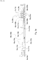
- Further features and advantages of the invention will become more evident from the detailed description of a preferred embodiment thereof, given by way of non limiting example, with reference to the attached drawing, in which:
-
Fig. 1
Figure 1 is a perspective view of a sliding device according to the invention; -
Fig. 2a
Figure 2a is a cross-sectional view of the sliding device ofFigure 1 taken along the line II-II, shown in a first, locking configuration; -
Fig. 2b
Figure 2b shows the sliding device ofFigure 2a in a second, unlocking configuration; -
Fig. 3a
Figure 3a is a cross-sectional view of the sliding device ofFigure 1 taken along the line II-II from an opposite point of view, shown in a first, locking configuration; -
Fig. 3b
Figure 3b shows the sliding device ofFigure 3a in a second, unlocking configuration; -
Fig. 4a
Figure 4a is a perspective, cutaway view of a connecting member of the sliding device ofFigure 1 , shown in a first, locking configuration; -
Fig. 4b
Figure 4b shows the connecting member ofFigure 4a in a second, unlocking configuration. - With reference to
Figure 1 , a slidingdevice 10 according to the invention is shown. - In a per se known manner, the sliding
device 10 comprises a pair ofparallel tracks lower rail upper rail - Each
upper rail lower rail - In order to selectively allow / prevent a sliding movement of the upper rails relative to the lower rails of the
tracks track - One of said locking assemblies can be seen in detail, for instance, in
Figures 4a - 4b . It is to be intended that the other locking assembly is identical to the one shown inFigures 4a - 4b . - Each locking
assembly support plate upper rail - The support plate may be, for instance, welded and/or staked to the respective
upper rail support plates orbital rivet upper rail - Since the
support plates - Each locking
assembly more locking pins apertures upper rail holes support plate apertures lower rail - The locking pins 5a, 5b have a substantially cylindrical body ending with a conical or frusto-conical tip for facilitating their insertion into said apertures of the lower rails.
- The locking pins 5a, 5b are biased to their locking configuration, in which at least some of them penetrate into corresponding apertures of the respective lower rail. To this purpose, a
helical spring pin - In a per se known manner, the locking pins 5a, 5b and the
corresponding apertures - In order to allow a user to adjust the position of the seat relative to the vehicle floor, the locking arrangement of the sliding device according to the invention also comprises a releasing assembly for moving the locking pins 5a, 5b from the aforesaid locking configuration to an unlocking configuration, in which all the locking pins are extracted from the apertures of the respective lower rail, thus allowing the upper rails to slide relative to the lower rails.
- As shown in
Figures 2a ,2b and3a ,3b , the releasing assembly generally comprises a releasingmember 9 and a pair of connectingmembers assembly member 9, on one hand, and with the locking pins 5a, 5b of the respective locking assembly, on the other hand. - According to the invention, the releasing assembly is configured so that a rotational movement of the releasing member is converted into a vertically oriented, translational movement of the locking pins.
- In the shown embodiment, the releasing member is made as a "U"-shaped releasing handle or
towel bar 9 comprising amiddle gripping portion 9c and two substantiallyparallel arms respective track - Each
arm pin slot bracket upper rail - Thanks to the engagement of said
pin slot portion 9c of the releasing handle, the rotational movement of saidgripping portion 9c is converted into a translational movement of the end portions of thearms arms - In the shown embodiment, each connecting
member coupling portion respective arm coupling portion - Each connecting
member portion respective locking assembly - In the shown embodiment, the engaging portion is made as an
engaging plate support plate - Preferably, the engaging plate substantially extends from the rear end of said support plate and projects beyond the front end of said support plate, which is correspondingly provided with a channel for the passage of said engaging plate.
- The
engaging plate apertures lower rail - The
engaging plate underlying support plate plate underlying support plate - Such parallelogram linkage comprises a first joint 23a, 23b, which is pivotally connected to said support plate at a first end by means of a
first pivot pin second pivot pin third pivot pin fourth pivot pin second joints support plate engaging plate - As better visible in
Figures 4a and4b , for allowing the locking pins 5a, 5b to be driven by the engagingplate radial collar - The window in the
engaging plate radial collars - Said
radial collars plate apertures lower rails - In an alternative embodiment, the radial collars may be replaced by one or more pegs transversely extending from the body of the locking pins.
- The operation of the locking arrangement of the sliding device according to the invention can be summarized as follows.
- In a rest condition, the
springs locking assemblies apertures lower rails Figures 2a ,3a ,4a ). In such a locking configuration, theupper rails lower rails - When a user wishes to adjust the position of the vehicle seat relative to the vehicle floor, he / she applies a force to the releasing
handle 9, by rotating the middle grippingportion 9c of said handle upwards. - As the gripping
portion 9c is rotated, thepins arms slots members coupling portions - As a result, the engaging portions (engaging plates) 21a, 21b of the connecting members move upwards and the edges of the windows of said
engaging portions radial collars - By overcoming the elastic resistance of the
springs portions apertures apertures lower rail Figures 2b ,3b ,4b ). In such an unlocking configuration, theupper rails lower rails - It is to be noted that thanks to the provision of a four-bar linkage (parallelogram linkage) between the engaging
portions respective support plates - When the user releases the releasing
handle 9, thesprings lower rail - The several advantages of the sliding device according to the invention will be evident to the person skilled in the art:
- the connecting members connecting the releasing member to the locking assemblies are completely arranged inside the tracks of the sliding device, between the upper and lower rails, which results in an extremely compact design;
- as the connecting members are completely arranged inside the tracks of the sliding device, they are not exposed to dust and dirt;
- since the locking pins move along a substantially linear path when switching from their locking to their unlocking configuration, and vice versa, the risk of jamming is avoided;
- the movement of the locking pins along a substantially linear path contributes to obtain a very compact design;
- when using a four-bar linkage, the stroke of the locking pins is guaranteed and independent from the stiffness of the connecting members.
- The above description of a preferred embodiment of the invention has been given merely by way of example and several variants and modifications within the reach of the person skilled in the art can be envisaged, as long as they remain within the scope of the invention as defined by the appended claims.
Claims (9)
- Sliding device (10) for a vehicle seat, comprising a pair of parallel tracks (20a, 20b), each comprising a lower rail (30a, 30b) and an upper rail (40a, 40b), each of said upper rails (40a, 40b) being constrained to a respective lower rail, but slidable relative to said lower rail, wherein said lower rails (30a, 30b) are provided with a plurality of apertures (32a, 32b) arranged along the longitudinal axes of said lower rails, wherein said sliding device is provided with a locking arrangement including two locking assemblies, one for each of said tracks (20a, 20b), wherein each of said locking assemblies (1a, 1b) comprises a support plate (3a, 3b) fastened to the respective upper rail (40a, 40b) and one or more locking pins (5a, 5b), which are configured to pass through said support plate (3a, 3b) and penetrate into corresponding apertures (32a, 32b) of the respective lower rail (30a, 30b), wherein said locking arrangement further comprises a releasing assembly for moving said locking pins (5a, 5b) from a locking configuration to an unlocking configuration, wherein said releasing assembly comprises a releasing member (9) and a pair of connecting members (17a, 17b), one for each locking assembly (1a, 1b), being entirely received within the respective tracks (20a, 20b) and arranged between the upper rail and the lower rail of the respective track, each connecting member (17a, 17b) being in a force transmission connection with said releasing member (9), on one hand, and with said locking pins (5a, 5b) of said locking assembly, on the other hand, wherein said releasing assembly is configured to convert a rotational movement of said releasing member (9) into a translational movement of said locking pins (5a, 5b), characterized in that said releasing member is made as a "U"-shaped releasing handle (9) comprising a middle gripping portion (9c) and two substantially parallel arms (9a, 9b), each penetrating into a respective track, and wherein each arm (9a, 9b) of said releasing handle is provided with a transversely protruding pin (11a, 11b) which is received in a kidney-shaped slot (13a, 13b) arranged in a bracket (15a, 15b) fastened to the respective upper rail (40, 40b).
- Sliding device (10) according to claim 1, wherein each of said connecting members (17a, 17b) comprises a coupling portion (19a, 19b) for coupling with the end portion of the respective one of said arms (9a, 9b) of said releasing handle, and an engaging portion (21a, 21b) for engaging said locking pins (5a, 5b) of said locking assemblies (1a, 1b).
- Sliding device (10) according to claim 2, wherein said engaging portion of said connecting members is made as an engaging plate (21a, 21b) which is arranged above the support plate (3a, 3b) of the locking assembly.
- Sliding device (10) according to claim 3, wherein each of said engaging plates (21a, 21b) is connected to the respective support plate (3a, 3b) by means of a four-bar linkage, preferably by means of a parallelogram linkage.
- Sliding device (10) according to claim 4, wherein said four-bar linkage comprises a first joint (23a, 23b), which is pivotally connected to said support plate at a first end by means of a first pivot pin (25a, 25b) and is pivotally connected to said engaging plate at a second, opposite end by means of a second pivot pin (27a, 27b), and further comprises a second joint (29a, 29b), which is pivotally connected to said support plate at a first end by means of a third pivot pin (31a, 31b) and is pivotally connected to said engaging plate at a second, opposite end by means of a fourth pivot pin (33a, 33b).
- Sliding device (10) according to any of the claims 3 - 5, wherein each of said engaging plates (21a, 21b) is provided with a window, through which the locking pins (5a, 5b) pass, and wherein each of said locking pins is provided with an outwardly extending radial collar (39a, 39b), the width of said window of said engaging plate being larger than the width of said locking pins, but smaller than the sum of the width of said locking pins and of the width of said radial collars.
- Sliding device (10) according to claim 6, wherein said radial collars (39a, 39b) are arranged on the body of said locking pins (5a, 5b) so that they are substantially in abutment against said engaging plate (21a, 21b) when said locking pins are completely inserted in said apertures of said lower rails.
- Sliding device (10) according to any of the preceding claims, wherein each of said support plates (3a, 3b) is connected to the respective upper rail (40a, 40b) by orbital riveting.
- Sliding device (10) according to any of the preceding claims, wherein said locking pins (5a, 5b) are biased towards said apertures (32a, 32b) of said lower rails by means of springs (7a, 7b).
Applications Claiming Priority (2)
| Application Number | Priority Date | Filing Date | Title |
|---|---|---|---|
| IT201800008367 | 2018-09-05 | ||
| PCT/IB2019/056373 WO2020049377A1 (en) | 2018-09-05 | 2019-07-25 | Sliding device for a vehicle seat provided with an improved locking arrangement |
Publications (2)
| Publication Number | Publication Date |
|---|---|
| EP3668749A1 EP3668749A1 (en) | 2020-06-24 |
| EP3668749B1 true EP3668749B1 (en) | 2021-09-15 |
Family
ID=63965985
Family Applications (1)
| Application Number | Title | Priority Date | Filing Date |
|---|---|---|---|
| EP19770191.5A Active EP3668749B1 (en) | 2018-09-05 | 2019-07-25 | Sliding device for a vehicle seat provided with an improved locking arrangement |
Country Status (9)
| Country | Link |
|---|---|
| US (1) | US11192471B2 (en) |
| EP (1) | EP3668749B1 (en) |
| JP (1) | JP7024138B2 (en) |
| KR (1) | KR102295175B1 (en) |
| CN (1) | CN112672916B (en) |
| AR (1) | AR116034A1 (en) |
| ES (1) | ES2902532T3 (en) |
| TW (1) | TWI708694B (en) |
| WO (1) | WO2020049377A1 (en) |
Families Citing this family (5)
| Publication number | Priority date | Publication date | Assignee | Title |
|---|---|---|---|---|
| IT201800006569A1 (en) * | 2018-06-21 | 2019-12-21 | Sliding device for a vehicle seat having an improved locking system | |
| IT201800007333A1 (en) * | 2018-07-19 | 2020-01-19 | Slider for a vehicle seat equipped with an improved release assembly | |
| WO2020049377A1 (en) * | 2018-09-05 | 2020-03-12 | Martur Italy S.R.L. | Sliding device for a vehicle seat provided with an improved locking arrangement |
| FR3102720B1 (en) * | 2019-10-31 | 2021-11-12 | Faurecia Sieges Dautomobile | Slide for vehicle seat and vehicle seat comprising such a slide. |
| KR102729601B1 (en) * | 2022-06-15 | 2024-11-14 | 주식회사 다스 | Locking device for seat rail |
Family Cites Families (41)
| Publication number | Priority date | Publication date | Assignee | Title |
|---|---|---|---|---|
| US4881774A (en) * | 1988-11-07 | 1989-11-21 | Bertrand Faure Automobile | Memory seat track assembly for vehicle seat |
| US5100092A (en) * | 1990-03-05 | 1992-03-31 | Hoover Universal, Inc. | Two-way manual seat adjuster with full memory easy entry |
| US5568908A (en) * | 1994-12-02 | 1996-10-29 | Atoma International Inc. | Six-way manual seat adjustment assembly |
| JP3757320B2 (en) * | 1995-07-19 | 2006-03-22 | カイペル・ゲゼルシヤフト・ミツト・ベシユレンクテル ハフツング・ウント・コンパニ− | Device for adjusting the seat of a car in the longitudinal direction |
| DE19526317C2 (en) * | 1995-07-19 | 1997-07-03 | Keiper Recaro Gmbh Co | Device for the longitudinal adjustment of a motor vehicle seat |
| JP3627472B2 (en) * | 1997-10-13 | 2005-03-09 | 日産自動車株式会社 | Car seat slide device |
| FR2776581B1 (en) * | 1998-03-24 | 2000-06-02 | Faure Bertrand Equipements Sa | SLIDE FOR VEHICLE SEAT AND SEAT COMPRISING SUCH A SLIDE |
| JP4060466B2 (en) * | 1998-11-06 | 2008-03-12 | テイ・エス テック株式会社 | Operating mechanism |
| JP2001277912A (en) * | 2000-04-03 | 2001-10-10 | Toyo Seat Co Ltd | Seat slide device with walk-in mechanism |
| US20030006355A1 (en) | 2001-07-09 | 2003-01-09 | Horsfield Keith C. | Seat track assembly with locking mechanism |
| KR100442746B1 (en) * | 2001-11-08 | 2004-08-02 | 주식회사다스 | Locking system of seat rail for vehicle |
| US6637712B1 (en) | 2002-05-17 | 2003-10-28 | Dura Global Technologies, Inc. | Automotive seat track lock mechanism with positive engagement |
| US6869057B2 (en) * | 2002-12-20 | 2005-03-22 | Fuji Kiko Co., Ltd. | Seat slide device |
| JP4234470B2 (en) * | 2003-03-13 | 2009-03-04 | 株式会社東洋シート | Seat slide device |
| JP4226381B2 (en) * | 2003-04-21 | 2009-02-18 | 岐阜車体工業株式会社 | Lock mechanism in vehicle seat track sliding device |
| KR100916395B1 (en) * | 2005-10-26 | 2009-09-07 | 기아자동차주식회사 | Car seat sliding device |
| WO2007095762A1 (en) | 2006-02-27 | 2007-08-30 | Intier Automotive Inc. | Leaf spring track latch |
| JP2007308109A (en) * | 2006-05-22 | 2007-11-29 | Shiroki Corp | Seat track device |
| JP4355963B2 (en) * | 2007-01-30 | 2009-11-04 | 株式会社今仙電機製作所 | Slide rail device |
| DE102007027321A1 (en) | 2007-06-14 | 2009-02-05 | Brose Fahrzeugteile Gmbh & Co. Kommanditgesellschaft, Coburg | Locking device for a rail adjustment system |
| JP5509980B2 (en) * | 2010-03-25 | 2014-06-04 | アイシン精機株式会社 | Vehicle seat slide device |
| JP5551486B2 (en) * | 2010-03-29 | 2014-07-16 | デルタ工業株式会社 | Seat slide lock device |
| US9393883B2 (en) * | 2010-09-29 | 2016-07-19 | Lear Corporation | Adjustable seat track having track engagement structure |
| DE102011017378B3 (en) | 2011-04-07 | 2012-04-19 | Keiper Gmbh & Co. Kg | Longitudinal adjuster for a vehicle seat |
| KR101407259B1 (en) * | 2012-11-28 | 2014-06-13 | 현대다이모스(주) | Seat rail locking apparatus of vehicle |
| JP5991207B2 (en) * | 2013-01-18 | 2016-09-14 | トヨタ紡織株式会社 | Slide rail |
| KR20160083210A (en) * | 2014-12-30 | 2016-07-12 | 현대다이모스(주) | Apparatus for locking seat-rail in vehicle and manufacturing method thereof |
| US9409497B1 (en) * | 2015-05-22 | 2016-08-09 | AISIN Technical Center of America, Inc. | Anti-unlock towel bar |
| US9902295B2 (en) * | 2015-08-25 | 2018-02-27 | Fisher & Company, Incorporated | Single-stage gear reduction output mechanism with a locking fork providing anti-back drive capability for automotive seat adjuster drives |
| KR101677914B1 (en) | 2015-12-03 | 2016-11-21 | 주식회사 서연씨엔에프 | Vehicle seat track having release lever for locking off |
| JP2017214058A (en) * | 2016-05-26 | 2017-12-07 | トヨタ紡織株式会社 | Seat slide device |
| FR3062608B1 (en) * | 2017-02-09 | 2019-04-05 | Renault S.A.S | REVERSIBLE LOCKING LOCKING DEVICE OF THE LONGITUDINAL POSITION OF A SEAT AND A SEAT ASSEMBLY COMPRISING THE SAME |
| CN108128219B (en) * | 2017-12-20 | 2024-03-08 | 安道拓(重庆)汽车部件有限公司 | Automobile seat inner locking type slide rail |
| CN207737153U (en) | 2017-12-20 | 2018-08-17 | 重庆延锋安道拓汽车部件系统有限公司 | The manual sliding rail of inner-lock-type of automotive seat |
| IT201800005731A1 (en) | 2018-05-25 | 2019-11-25 | Slider for a vehicle seat | |
| IT201800006569A1 (en) | 2018-06-21 | 2019-12-21 | Sliding device for a vehicle seat having an improved locking system | |
| IT201800006570A1 (en) | 2018-06-21 | 2019-12-21 | Sliding device for a vehicle seat having an improved locking system | |
| IT201800006650A1 (en) | 2018-06-26 | 2019-12-26 | Sliding device for a vehicle seat having an improved locking system | |
| IT201800007333A1 (en) | 2018-07-19 | 2020-01-19 | Slider for a vehicle seat equipped with an improved release assembly | |
| WO2020049377A1 (en) * | 2018-09-05 | 2020-03-12 | Martur Italy S.R.L. | Sliding device for a vehicle seat provided with an improved locking arrangement |
| IT201900000313A1 (en) | 2019-01-09 | 2020-07-09 | Martur Italy Srl | Slider for a vehicle seat with an improved rail configuration |
-
2019
- 2019-07-25 WO PCT/IB2019/056373 patent/WO2020049377A1/en not_active Ceased
- 2019-07-25 JP JP2021510985A patent/JP7024138B2/en active Active
- 2019-07-25 EP EP19770191.5A patent/EP3668749B1/en active Active
- 2019-07-25 US US17/272,440 patent/US11192471B2/en active Active
- 2019-07-25 CN CN201980058144.3A patent/CN112672916B/en active Active
- 2019-07-25 KR KR1020217009232A patent/KR102295175B1/en active Active
- 2019-07-25 ES ES19770191T patent/ES2902532T3/en active Active
- 2019-08-06 TW TW108127907A patent/TWI708694B/en active
- 2019-08-29 AR ARP190102460A patent/AR116034A1/en active IP Right Grant
Also Published As
| Publication number | Publication date |
|---|---|
| TWI708694B (en) | 2020-11-01 |
| WO2020049377A1 (en) | 2020-03-12 |
| JP7024138B2 (en) | 2022-02-22 |
| KR102295175B1 (en) | 2021-08-30 |
| US11192471B2 (en) | 2021-12-07 |
| JP2021526999A (en) | 2021-10-11 |
| CN112672916B (en) | 2022-03-01 |
| CN112672916A (en) | 2021-04-16 |
| AR116034A1 (en) | 2021-03-25 |
| TW202014318A (en) | 2020-04-16 |
| US20210245632A1 (en) | 2021-08-12 |
| ES2902532T3 (en) | 2022-03-28 |
| KR20210044286A (en) | 2021-04-22 |
| EP3668749A1 (en) | 2020-06-24 |
Similar Documents
| Publication | Publication Date | Title |
|---|---|---|
| EP3668749B1 (en) | Sliding device for a vehicle seat provided with an improved locking arrangement | |
| EP3615372B1 (en) | Sliding device for a vehicle seat provided with an improved locking arrangement | |
| EP3612411B1 (en) | Sliding device for a vehicle seat provided with an improved locking arrangement | |
| EP3621847B1 (en) | Sliding device for a vehicle seat provided with an improved releasing assembly | |
| CN110869240B (en) | Sliding device provided with an improved locking structure for a vehicle seat | |
| BR112020025378B1 (en) | SLIDING DEVICE FOR A VEHICLE SEAT |
Legal Events
| Date | Code | Title | Description |
|---|---|---|---|
| STAA | Information on the status of an ep patent application or granted ep patent |
Free format text: STATUS: UNKNOWN |
|
| STAA | Information on the status of an ep patent application or granted ep patent |
Free format text: STATUS: THE INTERNATIONAL PUBLICATION HAS BEEN MADE |
|
| PUAI | Public reference made under article 153(3) epc to a published international application that has entered the european phase |
Free format text: ORIGINAL CODE: 0009012 |
|
| STAA | Information on the status of an ep patent application or granted ep patent |
Free format text: STATUS: REQUEST FOR EXAMINATION WAS MADE |
|
| 17P | Request for examination filed |
Effective date: 20200316 |
|
| AK | Designated contracting states |
Kind code of ref document: A1 Designated state(s): AL AT BE BG CH CY CZ DE DK EE ES FI FR GB GR HR HU IE IS IT LI LT LU LV MC MK MT NL NO PL PT RO RS SE SI SK SM TR |
|
| AX | Request for extension of the european patent |
Extension state: BA ME |
|
| GRAP | Despatch of communication of intention to grant a patent |
Free format text: ORIGINAL CODE: EPIDOSNIGR1 |
|
| STAA | Information on the status of an ep patent application or granted ep patent |
Free format text: STATUS: GRANT OF PATENT IS INTENDED |
|
| DAV | Request for validation of the european patent (deleted) | ||
| DAX | Request for extension of the european patent (deleted) | ||
| INTG | Intention to grant announced |
Effective date: 20210607 |
|
| GRAS | Grant fee paid |
Free format text: ORIGINAL CODE: EPIDOSNIGR3 |
|
| GRAA | (expected) grant |
Free format text: ORIGINAL CODE: 0009210 |
|
| STAA | Information on the status of an ep patent application or granted ep patent |
Free format text: STATUS: THE PATENT HAS BEEN GRANTED |
|
| AK | Designated contracting states |
Kind code of ref document: B1 Designated state(s): AL AT BE BG CH CY CZ DE DK EE ES FI FR GB GR HR HU IE IS IT LI LT LU LV MC MK MT NL NO PL PT RO RS SE SI SK SM TR |
|
| REG | Reference to a national code |
Ref country code: CH Ref legal event code: EP |
|
| REG | Reference to a national code |
Ref country code: DE Ref legal event code: R096 Ref document number: 602019007750 Country of ref document: DE |
|
| REG | Reference to a national code |
Ref country code: IE Ref legal event code: FG4D |
|
| REG | Reference to a national code |
Ref country code: AT Ref legal event code: REF Ref document number: 1430269 Country of ref document: AT Kind code of ref document: T Effective date: 20211015 |
|
| REG | Reference to a national code |
Ref country code: LT Ref legal event code: MG9D |
|
| REG | Reference to a national code |
Ref country code: NL Ref legal event code: MP Effective date: 20210915 |
|
| PG25 | Lapsed in a contracting state [announced via postgrant information from national office to epo] |
Ref country code: NO Free format text: LAPSE BECAUSE OF FAILURE TO SUBMIT A TRANSLATION OF THE DESCRIPTION OR TO PAY THE FEE WITHIN THE PRESCRIBED TIME-LIMIT Effective date: 20211215 Ref country code: HR Free format text: LAPSE BECAUSE OF FAILURE TO SUBMIT A TRANSLATION OF THE DESCRIPTION OR TO PAY THE FEE WITHIN THE PRESCRIBED TIME-LIMIT Effective date: 20210915 Ref country code: FI Free format text: LAPSE BECAUSE OF FAILURE TO SUBMIT A TRANSLATION OF THE DESCRIPTION OR TO PAY THE FEE WITHIN THE PRESCRIBED TIME-LIMIT Effective date: 20210915 Ref country code: BG Free format text: LAPSE BECAUSE OF FAILURE TO SUBMIT A TRANSLATION OF THE DESCRIPTION OR TO PAY THE FEE WITHIN THE PRESCRIBED TIME-LIMIT Effective date: 20211215 Ref country code: LT Free format text: LAPSE BECAUSE OF FAILURE TO SUBMIT A TRANSLATION OF THE DESCRIPTION OR TO PAY THE FEE WITHIN THE PRESCRIBED TIME-LIMIT Effective date: 20210915 Ref country code: SE Free format text: LAPSE BECAUSE OF FAILURE TO SUBMIT A TRANSLATION OF THE DESCRIPTION OR TO PAY THE FEE WITHIN THE PRESCRIBED TIME-LIMIT Effective date: 20210915 Ref country code: RS Free format text: LAPSE BECAUSE OF FAILURE TO SUBMIT A TRANSLATION OF THE DESCRIPTION OR TO PAY THE FEE WITHIN THE PRESCRIBED TIME-LIMIT Effective date: 20210915 |
|
| REG | Reference to a national code |
Ref country code: AT Ref legal event code: MK05 Ref document number: 1430269 Country of ref document: AT Kind code of ref document: T Effective date: 20210915 |
|
| PG25 | Lapsed in a contracting state [announced via postgrant information from national office to epo] |
Ref country code: LV Free format text: LAPSE BECAUSE OF FAILURE TO SUBMIT A TRANSLATION OF THE DESCRIPTION OR TO PAY THE FEE WITHIN THE PRESCRIBED TIME-LIMIT Effective date: 20210915 Ref country code: GR Free format text: LAPSE BECAUSE OF FAILURE TO SUBMIT A TRANSLATION OF THE DESCRIPTION OR TO PAY THE FEE WITHIN THE PRESCRIBED TIME-LIMIT Effective date: 20211216 |
|
| REG | Reference to a national code |
Ref country code: ES Ref legal event code: FG2A Ref document number: 2902532 Country of ref document: ES Kind code of ref document: T3 Effective date: 20220328 |
|
| PG25 | Lapsed in a contracting state [announced via postgrant information from national office to epo] |
Ref country code: AT Free format text: LAPSE BECAUSE OF FAILURE TO SUBMIT A TRANSLATION OF THE DESCRIPTION OR TO PAY THE FEE WITHIN THE PRESCRIBED TIME-LIMIT Effective date: 20210915 |
|
| PG25 | Lapsed in a contracting state [announced via postgrant information from national office to epo] |
Ref country code: IS Free format text: LAPSE BECAUSE OF FAILURE TO SUBMIT A TRANSLATION OF THE DESCRIPTION OR TO PAY THE FEE WITHIN THE PRESCRIBED TIME-LIMIT Effective date: 20220115 Ref country code: SM Free format text: LAPSE BECAUSE OF FAILURE TO SUBMIT A TRANSLATION OF THE DESCRIPTION OR TO PAY THE FEE WITHIN THE PRESCRIBED TIME-LIMIT Effective date: 20210915 Ref country code: SK Free format text: LAPSE BECAUSE OF FAILURE TO SUBMIT A TRANSLATION OF THE DESCRIPTION OR TO PAY THE FEE WITHIN THE PRESCRIBED TIME-LIMIT Effective date: 20210915 Ref country code: RO Free format text: LAPSE BECAUSE OF FAILURE TO SUBMIT A TRANSLATION OF THE DESCRIPTION OR TO PAY THE FEE WITHIN THE PRESCRIBED TIME-LIMIT Effective date: 20210915 Ref country code: PT Free format text: LAPSE BECAUSE OF FAILURE TO SUBMIT A TRANSLATION OF THE DESCRIPTION OR TO PAY THE FEE WITHIN THE PRESCRIBED TIME-LIMIT Effective date: 20220117 Ref country code: PL Free format text: LAPSE BECAUSE OF FAILURE TO SUBMIT A TRANSLATION OF THE DESCRIPTION OR TO PAY THE FEE WITHIN THE PRESCRIBED TIME-LIMIT Effective date: 20210915 Ref country code: NL Free format text: LAPSE BECAUSE OF FAILURE TO SUBMIT A TRANSLATION OF THE DESCRIPTION OR TO PAY THE FEE WITHIN THE PRESCRIBED TIME-LIMIT Effective date: 20210915 Ref country code: EE Free format text: LAPSE BECAUSE OF FAILURE TO SUBMIT A TRANSLATION OF THE DESCRIPTION OR TO PAY THE FEE WITHIN THE PRESCRIBED TIME-LIMIT Effective date: 20210915 Ref country code: CZ Free format text: LAPSE BECAUSE OF FAILURE TO SUBMIT A TRANSLATION OF THE DESCRIPTION OR TO PAY THE FEE WITHIN THE PRESCRIBED TIME-LIMIT Effective date: 20210915 Ref country code: AL Free format text: LAPSE BECAUSE OF FAILURE TO SUBMIT A TRANSLATION OF THE DESCRIPTION OR TO PAY THE FEE WITHIN THE PRESCRIBED TIME-LIMIT Effective date: 20210915 |
|
| REG | Reference to a national code |
Ref country code: DE Ref legal event code: R097 Ref document number: 602019007750 Country of ref document: DE |
|
| PLBE | No opposition filed within time limit |
Free format text: ORIGINAL CODE: 0009261 |
|
| STAA | Information on the status of an ep patent application or granted ep patent |
Free format text: STATUS: NO OPPOSITION FILED WITHIN TIME LIMIT |
|
| PG25 | Lapsed in a contracting state [announced via postgrant information from national office to epo] |
Ref country code: DK Free format text: LAPSE BECAUSE OF FAILURE TO SUBMIT A TRANSLATION OF THE DESCRIPTION OR TO PAY THE FEE WITHIN THE PRESCRIBED TIME-LIMIT Effective date: 20210915 |
|
| 26N | No opposition filed |
Effective date: 20220616 |
|
| PG25 | Lapsed in a contracting state [announced via postgrant information from national office to epo] |
Ref country code: SI Free format text: LAPSE BECAUSE OF FAILURE TO SUBMIT A TRANSLATION OF THE DESCRIPTION OR TO PAY THE FEE WITHIN THE PRESCRIBED TIME-LIMIT Effective date: 20210915 |
|
| PG25 | Lapsed in a contracting state [announced via postgrant information from national office to epo] |
Ref country code: MC Free format text: LAPSE BECAUSE OF FAILURE TO SUBMIT A TRANSLATION OF THE DESCRIPTION OR TO PAY THE FEE WITHIN THE PRESCRIBED TIME-LIMIT Effective date: 20210915 |
|
| REG | Reference to a national code |
Ref country code: CH Ref legal event code: PL |
|
| REG | Reference to a national code |
Ref country code: BE Ref legal event code: MM Effective date: 20220731 |
|
| PG25 | Lapsed in a contracting state [announced via postgrant information from national office to epo] |
Ref country code: LU Free format text: LAPSE BECAUSE OF NON-PAYMENT OF DUE FEES Effective date: 20220725 Ref country code: LI Free format text: LAPSE BECAUSE OF NON-PAYMENT OF DUE FEES Effective date: 20220731 Ref country code: CH Free format text: LAPSE BECAUSE OF NON-PAYMENT OF DUE FEES Effective date: 20220731 |
|
| PG25 | Lapsed in a contracting state [announced via postgrant information from national office to epo] |
Ref country code: BE Free format text: LAPSE BECAUSE OF NON-PAYMENT OF DUE FEES Effective date: 20220731 |
|
| P01 | Opt-out of the competence of the unified patent court (upc) registered |
Effective date: 20230601 |
|
| PG25 | Lapsed in a contracting state [announced via postgrant information from national office to epo] |
Ref country code: IE Free format text: LAPSE BECAUSE OF NON-PAYMENT OF DUE FEES Effective date: 20220725 |
|
| PG25 | Lapsed in a contracting state [announced via postgrant information from national office to epo] |
Ref country code: MK Free format text: LAPSE BECAUSE OF FAILURE TO SUBMIT A TRANSLATION OF THE DESCRIPTION OR TO PAY THE FEE WITHIN THE PRESCRIBED TIME-LIMIT Effective date: 20210915 Ref country code: CY Free format text: LAPSE BECAUSE OF FAILURE TO SUBMIT A TRANSLATION OF THE DESCRIPTION OR TO PAY THE FEE WITHIN THE PRESCRIBED TIME-LIMIT Effective date: 20210915 |
|
| PG25 | Lapsed in a contracting state [announced via postgrant information from national office to epo] |
Ref country code: HU Free format text: LAPSE BECAUSE OF FAILURE TO SUBMIT A TRANSLATION OF THE DESCRIPTION OR TO PAY THE FEE WITHIN THE PRESCRIBED TIME-LIMIT; INVALID AB INITIO Effective date: 20190725 |
|
| PG25 | Lapsed in a contracting state [announced via postgrant information from national office to epo] |
Ref country code: MT Free format text: LAPSE BECAUSE OF FAILURE TO SUBMIT A TRANSLATION OF THE DESCRIPTION OR TO PAY THE FEE WITHIN THE PRESCRIBED TIME-LIMIT Effective date: 20210915 |
|
| REG | Reference to a national code |
Ref country code: DE Ref legal event code: R081 Ref document number: 602019007750 Country of ref document: DE Owner name: MFI ITALY ENGINEERING S.R.L., IT Free format text: FORMER OWNER: MARTUR ITALY S.R.L., MILANO, IT |
|
| REG | Reference to a national code |
Ref country code: GB Ref legal event code: 732E Free format text: REGISTERED BETWEEN 20250619 AND 20250625 |
|
| PGFP | Annual fee paid to national office [announced via postgrant information from national office to epo] |
Ref country code: FR Payment date: 20250626 Year of fee payment: 7 |
|
| PGFP | Annual fee paid to national office [announced via postgrant information from national office to epo] |
Ref country code: ES Payment date: 20250929 Year of fee payment: 7 |
|
| PGFP | Annual fee paid to national office [announced via postgrant information from national office to epo] |
Ref country code: DE Payment date: 20250714 Year of fee payment: 7 |
|
| PGFP | Annual fee paid to national office [announced via postgrant information from national office to epo] |
Ref country code: IT Payment date: 20250714 Year of fee payment: 7 Ref country code: TR Payment date: 20250721 Year of fee payment: 7 |
|
| PGFP | Annual fee paid to national office [announced via postgrant information from national office to epo] |
Ref country code: GB Payment date: 20250724 Year of fee payment: 7 |
|
| REG | Reference to a national code |
Ref country code: ES Ref legal event code: PC2A Owner name: MFI ITALY ENGINEERING S.R.L. Effective date: 20251112 |