EP3668629B1 - Filtersystem, filter und verfahren - Google Patents
Filtersystem, filter und verfahren Download PDFInfo
- Publication number
- EP3668629B1 EP3668629B1 EP18755802.8A EP18755802A EP3668629B1 EP 3668629 B1 EP3668629 B1 EP 3668629B1 EP 18755802 A EP18755802 A EP 18755802A EP 3668629 B1 EP3668629 B1 EP 3668629B1
- Authority
- EP
- European Patent Office
- Prior art keywords
- filter
- positioning means
- supporting ring
- movement
- head
- Prior art date
- Legal status (The legal status is an assumption and is not a legal conclusion. Google has not performed a legal analysis and makes no representation as to the accuracy of the status listed.)
- Active
Links
Images


Classifications
-
- B—PERFORMING OPERATIONS; TRANSPORTING
- B01—PHYSICAL OR CHEMICAL PROCESSES OR APPARATUS IN GENERAL
- B01D—SEPARATION
- B01D27/00—Cartridge filters of the throw-away type
- B01D27/08—Construction of the casing
-
- B—PERFORMING OPERATIONS; TRANSPORTING
- B01—PHYSICAL OR CHEMICAL PROCESSES OR APPARATUS IN GENERAL
- B01D—SEPARATION
- B01D35/00—Filtering devices having features not specifically covered by groups B01D24/00 - B01D33/00, or for applications not specifically covered by groups B01D24/00 - B01D33/00; Auxiliary devices for filtration; Filter housing constructions
- B01D35/16—Cleaning-out devices, e.g. for removing the cake from the filter casing or for evacuating the last remnants of liquid
-
- B—PERFORMING OPERATIONS; TRANSPORTING
- B01—PHYSICAL OR CHEMICAL PROCESSES OR APPARATUS IN GENERAL
- B01D—SEPARATION
- B01D27/00—Cartridge filters of the throw-away type
- B01D27/10—Safety devices, e.g. by-passes
- B01D27/106—Anti-leakage or anti-return valves
-
- B—PERFORMING OPERATIONS; TRANSPORTING
- B01—PHYSICAL OR CHEMICAL PROCESSES OR APPARATUS IN GENERAL
- B01D—SEPARATION
- B01D35/00—Filtering devices having features not specifically covered by groups B01D24/00 - B01D33/00, or for applications not specifically covered by groups B01D24/00 - B01D33/00; Auxiliary devices for filtration; Filter housing constructions
- B01D35/005—Filters specially adapted for use in internal-combustion engine lubrication or fuel systems
-
- B—PERFORMING OPERATIONS; TRANSPORTING
- B01—PHYSICAL OR CHEMICAL PROCESSES OR APPARATUS IN GENERAL
- B01D—SEPARATION
- B01D35/00—Filtering devices having features not specifically covered by groups B01D24/00 - B01D33/00, or for applications not specifically covered by groups B01D24/00 - B01D33/00; Auxiliary devices for filtration; Filter housing constructions
- B01D35/14—Safety devices specially adapted for filtration; Devices for indicating clogging
- B01D35/153—Anti-leakage or anti-return valves
-
- B—PERFORMING OPERATIONS; TRANSPORTING
- B01—PHYSICAL OR CHEMICAL PROCESSES OR APPARATUS IN GENERAL
- B01D—SEPARATION
- B01D35/00—Filtering devices having features not specifically covered by groups B01D24/00 - B01D33/00, or for applications not specifically covered by groups B01D24/00 - B01D33/00; Auxiliary devices for filtration; Filter housing constructions
- B01D35/30—Filter housing constructions
- B01D35/306—Filter mounting adapter
-
- F—MECHANICAL ENGINEERING; LIGHTING; HEATING; WEAPONS; BLASTING
- F01—MACHINES OR ENGINES IN GENERAL; ENGINE PLANTS IN GENERAL; STEAM ENGINES
- F01M—LUBRICATING OF MACHINES OR ENGINES IN GENERAL; LUBRICATING INTERNAL COMBUSTION ENGINES; CRANKCASE VENTILATING
- F01M1/00—Pressure lubrication
- F01M1/10—Lubricating systems characterised by the provision therein of lubricant venting or purifying means, e.g. of filters
-
- F—MECHANICAL ENGINEERING; LIGHTING; HEATING; WEAPONS; BLASTING
- F01—MACHINES OR ENGINES IN GENERAL; ENGINE PLANTS IN GENERAL; STEAM ENGINES
- F01M—LUBRICATING OF MACHINES OR ENGINES IN GENERAL; LUBRICATING INTERNAL COMBUSTION ENGINES; CRANKCASE VENTILATING
- F01M11/00—Component parts, details or accessories, not provided for in, or of interest apart from, groups F01M1/00 - F01M9/00
- F01M11/03—Mounting or connecting of lubricant purifying means relative to the machine or engine; Details of lubricant purifying means
-
- F—MECHANICAL ENGINEERING; LIGHTING; HEATING; WEAPONS; BLASTING
- F16—ENGINEERING ELEMENTS AND UNITS; GENERAL MEASURES FOR PRODUCING AND MAINTAINING EFFECTIVE FUNCTIONING OF MACHINES OR INSTALLATIONS; THERMAL INSULATION IN GENERAL
- F16N—LUBRICATING
- F16N39/00—Arrangements for conditioning of lubricants in the lubricating system
- F16N39/06—Arrangements for conditioning of lubricants in the lubricating system by filtration
-
- B—PERFORMING OPERATIONS; TRANSPORTING
- B01—PHYSICAL OR CHEMICAL PROCESSES OR APPARATUS IN GENERAL
- B01D—SEPARATION
- B01D2201/00—Details relating to filtering apparatus
- B01D2201/04—Supports for the filtering elements
- B01D2201/0415—Details of supporting structures
-
- B—PERFORMING OPERATIONS; TRANSPORTING
- B01—PHYSICAL OR CHEMICAL PROCESSES OR APPARATUS IN GENERAL
- B01D—SEPARATION
- B01D2201/00—Details relating to filtering apparatus
- B01D2201/29—Filter cartridge constructions
-
- B—PERFORMING OPERATIONS; TRANSPORTING
- B01—PHYSICAL OR CHEMICAL PROCESSES OR APPARATUS IN GENERAL
- B01D—SEPARATION
- B01D2201/00—Details relating to filtering apparatus
- B01D2201/29—Filter cartridge constructions
- B01D2201/291—End caps
-
- B—PERFORMING OPERATIONS; TRANSPORTING
- B01—PHYSICAL OR CHEMICAL PROCESSES OR APPARATUS IN GENERAL
- B01D—SEPARATION
- B01D2201/00—Details relating to filtering apparatus
- B01D2201/30—Filter housing constructions
- B01D2201/301—Details of removable closures, lids, caps, filter heads
- B01D2201/304—Seals or gaskets
-
- B—PERFORMING OPERATIONS; TRANSPORTING
- B01—PHYSICAL OR CHEMICAL PROCESSES OR APPARATUS IN GENERAL
- B01D—SEPARATION
- B01D2201/00—Details relating to filtering apparatus
- B01D2201/34—Seals or gaskets for filtering elements
- B01D2201/347—Radial sealings
-
- B—PERFORMING OPERATIONS; TRANSPORTING
- B01—PHYSICAL OR CHEMICAL PROCESSES OR APPARATUS IN GENERAL
- B01D—SEPARATION
- B01D2201/00—Details relating to filtering apparatus
- B01D2201/40—Special measures for connecting different parts of the filter
- B01D2201/4007—Use of cam or ramp systems
-
- B—PERFORMING OPERATIONS; TRANSPORTING
- B01—PHYSICAL OR CHEMICAL PROCESSES OR APPARATUS IN GENERAL
- B01D—SEPARATION
- B01D2201/00—Details relating to filtering apparatus
- B01D2201/40—Special measures for connecting different parts of the filter
- B01D2201/4023—Means for connecting filter housings to supports
-
- B—PERFORMING OPERATIONS; TRANSPORTING
- B01—PHYSICAL OR CHEMICAL PROCESSES OR APPARATUS IN GENERAL
- B01D—SEPARATION
- B01D2201/00—Details relating to filtering apparatus
- B01D2201/40—Special measures for connecting different parts of the filter
- B01D2201/4046—Means for avoiding false mounting of different parts
-
- B—PERFORMING OPERATIONS; TRANSPORTING
- B01—PHYSICAL OR CHEMICAL PROCESSES OR APPARATUS IN GENERAL
- B01D—SEPARATION
- B01D2201/00—Details relating to filtering apparatus
- B01D2201/40—Special measures for connecting different parts of the filter
- B01D2201/4076—Anti-rotational means
-
- F—MECHANICAL ENGINEERING; LIGHTING; HEATING; WEAPONS; BLASTING
- F01—MACHINES OR ENGINES IN GENERAL; ENGINE PLANTS IN GENERAL; STEAM ENGINES
- F01M—LUBRICATING OF MACHINES OR ENGINES IN GENERAL; LUBRICATING INTERNAL COMBUSTION ENGINES; CRANKCASE VENTILATING
- F01M11/00—Component parts, details or accessories, not provided for in, or of interest apart from, groups F01M1/00 - F01M9/00
- F01M11/03—Mounting or connecting of lubricant purifying means relative to the machine or engine; Details of lubricant purifying means
- F01M2011/031—Mounting or connecting of lubricant purifying means relative to the machine or engine; Details of lubricant purifying means characterised by mounting means
Definitions
- the invention relates to a filter system for a liquid medium to be filtered, in particular fuel or oil, in particular lubricating oil, in particular for the internal combustion engine of a motor vehicle.
- the filter system comprises a filter head with an idle channel at the bottom for the fluid and with a stop element as well as a filter which can be mounted on the filter head by means of a screwing-in movement directed about its longitudinal axis.
- the filter has at one end a support ring which is rotatably attached to the filter relative to the longitudinal axis, the support ring having an eccentrically arranged closure element for the idle channel and a first positioning means that can be guided by means of the screwing-in movement against the stop element of the filter head relative to the support ring to position the filter head in a predetermined rotational position with the closure element axially aligned with the idle channel, so that the closure element can be transferred into its sealing seat on the filter head that closes the idle channel by an axial movement of the filter derived from the screwing-in movement.
- a filter system mentioned at the beginning is, for example, from WO 2009/083285 A1 known.
- the filter is designed as a replaceable filter cartridge with an integral housing part.
- the support ring with the closure element arranged on it is inevitably rotated against the screwing-in movement of the filter and - due to the mutual thread engagement of the replaceable filter cartridge and the filter head - is torn axially and laterally out of its sealing seat on the filter head.
- This can result in a considerable transverse load on the closure element, which may be firmly adhering in the sealing seat on the filter head. In the worst case, this can lead to parts of the closure element or the entire closure element being torn off.
- the closure element in the known filter system cannot be designed as a sealing plug which can be introduced into the idle channel and which is characterized by a particularly reliable sealing capacity.
- document DE 2020 09002455U discloses a replaceable filter cartridge with a closure element for an idle channel.
- document EP 3120914 A1 discloses a filter device with an exchangeable filter element and a carrier, the carrier having a pin for insertion into an idle channel.
- the problem relating to the filter system is achieved by a filter system with the features specified in claim 1.
- the filter according to the invention has the features specified in claim 10 and the method according to the invention has the features specified in claim 14.
- the support ring of the filter has, according to the invention, a second positioning means by which the support ring is held in a rotationally fixed manner when the filter is unscrewed in the opposite direction to the screwing-in movement in order to loosen the closure element from its sealing seat on the filter head, so that the closure element is only axially Direction can be moved out of its sealing seat.
- the second positioning means thus blocks a rotational adjustment of the support ring about the longitudinal axis of the filter when the filter is unscrewed in the opposite direction to the screwing-in movement.
- the second positioning means can be supported in particular on the abovementioned stop element of the filter head or also on a rotary stop arranged at a distance from the stop element and thereby (initially) prevent undesired rotation of the support ring with the filter.
- the closure element By axially moving the filter away from the filter head derived from the unscrewing movement, the closure element can be moved axially, in particular strictly axially, out of its sealing seat and thus an excessive transverse loading of the closure element can be prevented. A tearing off of parts of the closure element or of the entire closure element from the support ring can thus be reliably counteracted.
- the second positioning means forms a rotation protection for the support ring or the closure element arranged on it until the closure element is reliably freed from its sealing seat in the axial direction and the second positioning means in the circumferential direction of the support ring from its overlap with a corresponding rotary stop, in particular the stop element of the The filter head is disengaged in the axial direction.
- the closure element can also easily be designed as a closure plug that is in the sealing seat at least in sections protrudes into the idle channel of the filter head and thus offers a particularly reliable sealing ability.
- the support ring can be constructed in one piece in a structurally simple and inexpensive manner.
- the support ring can also be constructed in several parts, in particular in segments, in order to simplify manufacture and assembly.
- the support ring has a contour that is raised in the axial direction over the closure means and the two positioning means;
- the support ring can be formed in one piece or in several pieces, in particular in segments.
- the two positioning means can be arranged so far apart from one another on the support ring that the stop element of the filter head can be inserted with a sliding play form fit or with only little play between the two positioning means. A particularly secure guidance of the support ring on the stop element in the axial direction can thereby be achieved.
- the two positioning means are designed in the form of webs.
- the second positioning means preferably extends less far away from the end face of the filter in the axial direction than the first positioning means.
- the second positioning means is thus arranged with its free axial end pointing away from the end face of the filter, axially set back in the direction of the end face with respect to the corresponding free axial end of the first positioning means.
- the positioning means can also extend equally far away from the support ring in the axial direction.
- the free ends of the two stop elements can also be arranged at the same height in the axial direction.
- the two positioning means are preferably radial Arranged offset from one another in the direction, that is to say at different distances from the longitudinal axis of the filter.
- the stop means forms two stop areas for the positioning aids, which are offset from one another in the axial and radial directions, so that when the filter (moved in the screwing direction) is mounted on the filter head, only or first the first positioning means strikes the stop element.
- the two positioning means can be arranged in a substantially identical radial position between the outer and inner circumferential contour of the support ring; this ensures in a structurally simple manner that only the filter suitable for the predetermined application is used.
- the stop for the two positioning means in the filter head can preferably be designed with a larger axial extension away from the end face of the filter head than the upper edge of the drainage channel.
- the two positioning means can be arranged on the end face and / or circumferentially on the support ring. If the positioning means are formed on the circumference of the support ring, a mechanically stable connection of the positioning means on the support ring can thereby be achieved in a simplified manner.
- the closure element can in particular extend away from the support ring in the axial direction.
- the closure element is designed as a closure plug which can be introduced into the idle channel at least in sections in the axial direction.
- the sealing plug serves at least partially as a radial sealing element.
- the closure element can additionally or alternatively be adapted to the shape of the drainage channel.
- the closure element can be kidney-shaped, for example. Kidney-shaped here means that the closure element is essentially round or elliptical in the base area and has a depression or indentation in the outer contour, so that the sign of the direction of curvature of the outer contour changes at least once, the depression or indentation dividing the base area in two, in particular essentially rounded, dividing areas.
- the division can be symmetrical or also be asymmetrical, so that two areas of the same size arise in the area or the first area has a larger area than the second area.
- This embodiment has the advantage that the positioning accuracy can be ensured in a structurally simple manner, in other words the sealant strikes the sealing seat in a structurally simple manner and reliably covers it.
- the closure element can be provided with an elastomeric radial and / or an axial sealing element or designed as such an elastomeric radial and / or axial sealing element for the purpose of a particularly reliable sealing capability. A reliable, fluid-tight seal of the idle channel can thereby be ensured.
- the closure element can additionally have a seal holding structure, preferably designed as an annular groove, for the aforementioned radial or axial seal element. This eliminates the need for additional gluing or foaming of the sealing element on the closure element.
- the closure element can be arranged adjacent to the first and / or to the second positioning means.
- adjacent means that the closure element and the first and second positioning means are preferably arranged in two adjacent quadrants of the support ring, particularly preferably in one quadrant of the support ring.
- the closure element and the positioning means are arranged in two adjacent quadrants of the support ring
- the closure element can be arranged in a first quadrant of the support ring and the positioning means can be arranged in a second quadrant of the support ring.
- the closure element and the first or the second positioning means can also be arranged in the first quadrant of the support ring and the respective other positioning means can be arranged in a second quadrant adjacent thereto.
- opposite means that the closure element is arranged on a first semicircular segment of the support ring and the first and second positioning means are arranged on the second semicircular segment of the support ring are, wherein the center of the closure element and the center of the distance between the two positioning means preferably form the respective reference point and these reference points are preferably arranged opposite one another.
- the second positioning means of the support ring can, according to the invention, have an end face slope for the stop element.
- undesired tilting of the second positioning means on the stop element can be counteracted when the filter is mounted on the filter head.
- the two positioning means are preferably molded onto the support ring.
- the support ring can be produced in a particularly cost-effective manner and with low manufacturing tolerances by means of a plastic injection molding process. This is particularly advantageous in the case of mass production of the filter.
- the filter is designed as a replaceable filter cartridge.
- a replaceable filter cartridge also referred to as a replaceable filter, in the sense of the application is a filter cartridge that cannot be opened non-destructively; it comprises a housing with a cover, the housing being in particular made of metal or plastic.
- a filter element in particular an annular filter element, is arranged in the housing.
- the housing preferably has a cover section with an inlet, an outlet and a sealing seat arranged on the cover section.
- the outlet is preferably provided centrally in a first cover section, the seal seat is preferably arranged concentrically to the outlet on a second cover section and the inlet arranged in the cover, in particular in the second cover section, is preferably located between the outlet and the seal seat.
- the outlet preferably comprises a thread.
- the housing part of the filter which forms the cover comprises a first cover section arranged on the inside with a central flow opening and a second cover section arranged on the outside.
- the second outer cover section is here connected in a fluid-tight manner to the cup-shaped housing section of the housing part, for example crimped or welded.
- the first cover section of the housing part preferably has an (internal) thread over that the filter according to the invention can be screwed into an (external) thread of a connecting piece of the filter head.
- a circumferential sealing ring can be arranged on the front side of the housing part. The sealing ring can also have a sealing lip for circumferentially sealing contact with the filter head.
- a seal retaining ring can be provided for the sealing ring, the seal retaining ring forming part of the second cover section.
- the seal retaining ring is positively connected to the housing part of the filter, in particular flanged or welded.
- the replaceable filter cartridge according to the invention can be mounted on the filter head by means of a screwing-in movement directed around its longitudinal axis, the replaceable filter cartridge having a support ring at one end, which is fastened to the particularly cup-shaped housing part of the replaceable filter cartridge so as to be rotatable relative to the longitudinal axis of the replaceable filter cartridge, the support ring having an eccentrically arranged closure element for the idle channel and has a first web-shaped positioning means that can be guided by means of the screwing-in movement against the stop element of the filter head in order to position the support ring relative to the filter head in a predetermined rotational position with the closure element axially aligned with the idle channel, so that the closure element is caused by an axial movement derived from the screwing-in movement Filter can be transferred into its sealing seat on the filter head that closes the idle channel, the support ring having a second web-shaped positioning means by means of which the support ring can be held in a rotationally fixed manner when the filter is unscrewed in the
- At least one of the two positioning means extends in a radial direction away from the support ring.
- the two positioning means are particularly preferably arranged either inside the support ring circumference or outside the support ring circumference.
- the first and / or the second positioning means extends in a further embodiment in the axial direction beyond the closure element away from the end face of the filter, the first positioning means extending further than the second positioning means.
- a non-return membrane is additionally provided on the raw side in the housing of the filter, which is arranged on the raw side of the filter in the installation situation and prevents the liquid medium, for example an oil, from flowing back.
- Such replaceable filter cartridges thus have an integral housing part in which a filter element is arranged.
- the replaceable filter cartridges are particularly easy and convenient to use and are mostly used in what is known as the main flow, in which the entire fluid flow flows through the filter.
- the support ring can in particular be rotatably attached to a cover section of the housing part of the replaceable filter cartridge. From a structural and manufacturing point of view, the support ring is preferably hooked to the filter, in particular its cover section, that is to say held or connected by means of an undercut.
- the filter can also be designed as a filter insert to be exchangeably arranged in a filter housing.
- the filter system has a filter housing with the filter head and a housing part designed as a housing cover, which can be screwed into the thread of the filter head.
- the filter head is preferably designed in the form of a pot or as a housing pot which can be closed with the housing cover and which is used to hold the filter.
- the filter is advantageously held in a rotationally fixed manner and fixed in position in the axial direction on the housing part designed as a housing cover. This can be achieved, for example, in that the filter is locked to the housing cover.
- the filter can also be arranged held in a frictional connection on the housing part. Overall, this can result in Screwing the housing cover into the thread of the filter head and also when unscrewing the housing cover from the filter head ensures that the filter rotates at the same time.
- the support ring according to the invention can be arranged, in particular latched, on an end plate or a support tube of the filter in order to enable simple and inexpensive manufacture of the filter .
- the filter according to the invention for a filter system explained above is designed according to the invention as a replaceable filter cartridge.
- the filter is particularly easy and safe to use.
- Changing the filter according to the invention can also include, as a preceding step, the loosening and removal of a filter to be exchanged by an unscrewing movement in the opposite direction to the screwing-in movement, the support ring being held in a rotationally fixed manner during the loosening of the closure element from its sealing seat on the filter head, so that the closure element only in the axial direction can be moved out of the sealing seat.
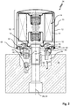
- a filter 10 designed as a replaceable filter cartridge for filtering a fluid, here for example lubricating oil for an internal combustion engine, is shown.
- the filter 10 here comprises a housing part 12, which comprises a cover, with a filter element 14 which is arranged in the housing 12 and which is shown in FIG Fig. 1 is shown highly schematically with a dashed line.
- a support ring 16 is arranged on one end of the filter 10. The support ring 16 surrounds the longitudinal axis 18 of the filter or the coincident filter element longitudinal axis 20 of the filter element 14 in an annular manner.
- the support ring 16 is rotatable about the longitudinal axis 18, ie freely rotatable, mounted on the housing part 12 of the filter 10 and can, for example, be designed as a plastic injection-molded part.
- a closure element 22 is arranged on the support ring 16.
- the closure element 22 extends away from the support ring 16 in an axial direction.
- the closure element 22 can in particular consist of a rubber-elastically deformable material, ie an elastomer.
- a first and a second positioning means 24, 26 are also arranged on the support ring 16.
- the two positioning means 24, 26 are preferably molded onto the support ring 16. Both positioning means 24, 26 extend from the end face away from the support ring 16 in the axial direction.
- the two positioning means 24, 26 are aligned parallel to one another and are arranged at a distance from one another in the circumferential direction of the support ring 16. It should be noted that the second positioning means 26 in the direction of an unscrewing or screwing-in movement of the filter 10, designated by 28, onto a connecting piece of an in Fig. 2
- the filter head shown in more detail is arranged in front of the first positioning means 24. As a result, a gap or receptacle 30 is formed between the two positioning means 24, 26.
- the first positioning means 24 here protrudes beyond the second positioning means 26 in the axial direction. In other words, the second positioning means 26 is with its free axial The end 32 is less spaced from an end face of the filter 10 than the free axial end 32 of the first positioning means 24.
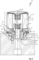
- a filter system 34 for filtering a fluid, in particular fuel or oil, in particular lubricating oil for the internal combustion engine of a motor vehicle (not shown) is shown.
- the filter system 34 comprises a filter 10 according to FIG Fig. 1 and a filter head 36 on which the filter 10 with the filter element 14 arranged therein is to be mounted.
- the filter head 36 is in Fig. 2 shown in a highly schematic manner and has an inlet channel 38 on the raw side, only partially shown, for the fluid to be filtered and an outlet channel 40 arranged on the clean side for the filtered fluid.
- a bottom-side idle channel, labeled 42 , of the filter head 36 is used to drain fluid contained in the filter 10 when the filter 10 is replaced and - following the force of gravity - to divert it in a controlled manner via the filter head 36.
- the idle channel 42 can be fluidically connected, for example, to an oil pan or a fuel tank (not shown).
- the idle channel 42 is closed in a fluid-tight manner by the closure element 22 of the replaceable filter cartridge fastened to the support ring 16.
- the fluid can be pumped through the filter 10 during filter operation and at the same time an undesired outflow of the fluid via the idle channel 42 can be prevented.
- the filter element 14 has a filter medium 44 which surrounds the filter element longitudinal axis 20 in an annular manner.
- the filter element 14 is therefore designed as a so-called round filter element.
- the filter medium 44 can be folded in a star shape in order to obtain the largest possible functional filter surface.
- the filter medium 44 can be arranged held between two end disks of the filter element 14. Other designs of the filter element 14 are easily conceivable.
- the housing part 12 of the filter 10 comprises a cover with a first, internally arranged cover section 46 with a central flow opening and a second, externally arranged cover section 48.
- the second outer cover section 48 is here fluid-tightly connected to the pot-shaped housing section 50 of the housing part 12, for example crimped or welded.
- the first cover section 46 of the housing part 12 has an (internal) thread 52 , via which the filter 10 can be screwed into an (external) thread 54 of a connecting piece 56 of the filter head 36.
- a circumferential sealing ring 58 is arranged on the front side of the housing part 12.
- the sealing ring 58 can according to Fig. 2 have a sealing lip 60 for circumferentially sealing contact with the filter head 36.
- the second cover section 48 can in particular have a seal retaining ring 68 for the sealing ring 58.
- the seal retaining ring 68 is positively connected to the housing part 12 of the filter, in particular crimped or welded.
- the support ring 16 can be hooked to the housing part 12 for the purpose of simple and inexpensive assembly.
- the support ring 16 has one or more hook elements 62 on the filter element side.
- the hook elements 62 here engage behind the second cover section 48, for example.
- a different type of rotatable fastening of the support ring 16 on the housing part 12 of the replaceable filter cartridge 10 is conceivable.
- the filter head 36 has a stop element 64 arranged at the bottom, which serves as a rotary stop for the support ring 16.
- the stop element 64 can according to Fig. 2 in particular extend away from the bottom portion 66 of the filter head 36 in an axial direction.
- the filter head 36 can be made of metal, for example aluminum.
- the stop element 64 can be molded onto the filter head 36 or else it can be designed as a separate component from the filter head 36. In the latter case, the stop element 64 can in particular consist of plastic.
- the support ring 16 When the filter 10 is screwed into the external thread 54 of the filter head 36, the support ring 16 is initially moved together with the filter 10 in the screwing-in direction 28.
- the mutual thread engagement of the filter 10 and the filter head 36 results in a feed movement of the filter 10 axially in the direction of the idle channel 42 or the stop element 64 of the filter head 36 Fig. 2
- the shown mounting state of the filter on the filter head 36 are the two positioning means 24, 26 of the support ring 16 is still axially spaced from the stop element 64.
- the stop element 64 does not yet extend into a rotational path (not shown) of the first positioning means 24 or the second positioning means 26 of the support ring 16.
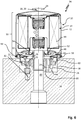
- Fig. 3 is the filter system 10 compared to a Fig. 2 shown later assembly time.
- the filter 10 is screwed further onto the connecting piece 56 of the filter head 36.
- the first positioning means 24 of the support ring 16 has almost reached the stop element 64 in the axial direction.
- the first positioning aid 24 of the support ring 16 is hit against the stop element 64 and thereby the support ring 16 is locked in a predetermined rotational position relative to the filter head 36 with the closure element 22 axially aligned with the drainage channel. This prevents the support ring 16 from rotating further along with the filter 10 in the screwing-in direction 28.
- the closure element 22 is arranged in its sealing seat on the filter head 36.
- the closure element 22 rests against a wall area of the bottom section 66 of the filter head 36 delimiting the idle channel 42 on the circumferential side in a sealing manner in the axial direction.
- the closure element 22 is therefore designed as an axial sealing element.
- the sealing ring 58 of the housing part 12 of the replaceable filter cartridge rests on the filter head 36 in a circumferential, sealing manner.
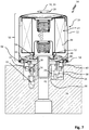
- FIG. 5 Another filter system 34 is shown which differs from that described above in connection with FIGS Figures 2 to 4
- the filter system 34 explained essentially differs in that the closure element 22 is designed as a closure plug that can be introduced into the idle channel 42 of the filter head 36.
- the closure element 22 is therefore designed as a radial sealing element.
- the closure element 22 is preferably made of an elastomer.
- the sectional view in Fig. 5 is selected in such a way that the second positioning means 26 can also be clearly seen.
- the filter 10 is still in its specified (operational) mounting position on the filter head 36 arranged.
- the sealing plug extends into the idle channel 42 in a sealing manner.
- the second positioning means 26 can rest against the stop element 64 in the circumferential direction of the support ring 16.
- the stop element 64 thus extends into the receptacle 30 formed between the two positioning means 24, 26 of the support ring 16 ( Fig. 1 ) into it.
- the second stop element prevents the support ring 16 from rotating with the housing part 12.
- the support ring 16 can be moved out of the idle channel 42 in a strictly axial direction by means of an axial movement of the filter 10 derived from the unscrewing or unscrewing movement of the filter with its sealing plug, as shown in FIG Fig. 6 is shown by way of example. Undesired transverse loading of the closure element 22 is thereby reliably prevented. The risk of parts of the closure element 22 or the entire closure element 22 tearing off from the support ring 16 is thus minimized.
- the support ring 16 can rotate with the filter 10 counter to the screwing-in direction 28.
- the second positioning means 26 and the stop element 64 as well as the closure element 22 and the idle channel 42 are coordinated in terms of their spatial arrangement or dimensions in such a way that a rotational release of the support ring 16 counter to the screwing-in direction 28 is only possible when the closure element is out of the idle channel is fully disengaged in the axial direction, as shown in Fig. 7 is shown.
- the filter 10 can also be designed as a conventional filter insert (without housing part 12) which can be arranged interchangeably in a filter housing having a housing part 12 and a filter head 36.
- the housing part 12 is designed as a filter housing cover in this case and is used to close the filter head 36, which can be clearly described as a cup-shaped design, which means that the filter head 36 has a fluid collection space that is connected to the drainage channel.
- the housing part 12 can be screwed into a thread of the filter head 36.
- the filter 10 is coupled in a rotationally fixed manner to the housing part 12, in particular latched to it or held thereon with a friction fit.
- the filter 10 can in this embodiment in one of the in the Figures 1 to 7
- the filter element 14 shown may be designed in a corresponding manner.
- the support ring 16 can be rotatably attached to an end disk or to a support tube of the filter 10.
Landscapes
- Chemical & Material Sciences (AREA)
- Chemical Kinetics & Catalysis (AREA)
- Engineering & Computer Science (AREA)
- General Engineering & Computer Science (AREA)
- Mechanical Engineering (AREA)
- Combustion & Propulsion (AREA)
- Lubrication Details And Ventilation Of Internal Combustion Engines (AREA)
Priority Applications (1)
| Application Number | Priority Date | Filing Date | Title |
|---|---|---|---|
| PL18755802T PL3668629T3 (pl) | 2017-08-15 | 2018-08-15 | Układ filtracyjny, filtr oraz sposób |
Applications Claiming Priority (3)
| Application Number | Priority Date | Filing Date | Title |
|---|---|---|---|
| DE102017007653 | 2017-08-15 | ||
| DE102017007654 | 2017-08-15 | ||
| PCT/EP2018/072103 WO2019034682A1 (de) | 2017-08-15 | 2018-08-15 | Filtersystem, filter und verfahren |
Publications (2)
| Publication Number | Publication Date |
|---|---|
| EP3668629A1 EP3668629A1 (de) | 2020-06-24 |
| EP3668629B1 true EP3668629B1 (de) | 2021-09-29 |
Family
ID=63244606
Family Applications (2)
| Application Number | Title | Priority Date | Filing Date |
|---|---|---|---|
| EP18755802.8A Active EP3668629B1 (de) | 2017-08-15 | 2018-08-15 | Filtersystem, filter und verfahren |
| EP18755803.6A Active EP3668630B1 (de) | 2017-08-15 | 2018-08-15 | Filterelement mit stirnseitiger standhilfe |
Family Applications After (1)
| Application Number | Title | Priority Date | Filing Date |
|---|---|---|---|
| EP18755803.6A Active EP3668630B1 (de) | 2017-08-15 | 2018-08-15 | Filterelement mit stirnseitiger standhilfe |
Country Status (5)
| Country | Link |
|---|---|
| US (2) | US20200179845A1 (pl) |
| EP (2) | EP3668629B1 (pl) |
| DE (2) | DE102018119809A1 (pl) |
| PL (1) | PL3668629T3 (pl) |
| WO (2) | WO2019034682A1 (pl) |
Families Citing this family (3)
| Publication number | Priority date | Publication date | Assignee | Title |
|---|---|---|---|---|
| WO2019034682A1 (de) * | 2017-08-15 | 2019-02-21 | Mann+Hummel Gmbh | Filtersystem, filter und verfahren |
| USD958288S1 (en) * | 2020-10-09 | 2022-07-19 | Mahle International Gmbh | Filter device |
| USD1103334S1 (en) | 2024-02-16 | 2025-11-25 | Emc Water Llc | Filter cartridge |
Family Cites Families (14)
| Publication number | Priority date | Publication date | Assignee | Title |
|---|---|---|---|---|
| DE10353424B4 (de) | 2003-11-15 | 2012-12-13 | Mahle Filtersysteme Gmbh | Flüssigkeitsfilter, insbesondere Ölfilter für ein Kraftfahrzeug, und zugehöriges Ringfilterelement |
| DE102007009352B4 (de) | 2007-02-23 | 2018-03-08 | Mahle International Gmbh | Flüssigkeitsfilter |
| DE102007062221A1 (de) | 2007-12-21 | 2009-06-25 | Mahle International Gmbh | Flüssigkeitsfilter |
| DE102008049006A1 (de) | 2008-09-25 | 2010-04-01 | Mahle International Gmbh | Flüssigkeitsfilter |
| DE202009002455U1 (de) * | 2009-02-02 | 2010-07-01 | Mann+Hummel Gmbh | Flüssigkeitsfilter |
| DE102010005980A1 (de) | 2010-01-28 | 2011-08-18 | MAHLE International GmbH, 70376 | Filtereinrichtung |
| FR2970421B1 (fr) | 2011-01-17 | 2013-02-22 | Filtrauto | Filtre et cartouche filtrante permettant une vidange decentree |
| DE202011105968U1 (de) | 2011-08-18 | 2011-12-06 | Mahle International Gmbh | Flüssigkeitsfilter, insbesondere ein Ölfilter |
| DE202011104690U1 (de) | 2011-08-18 | 2012-01-16 | Mahle International Gmbh | Flüssigkeitsfilter, insbesondere Ölfilter |
| EP2703056B1 (en) * | 2012-09-04 | 2016-11-02 | A.L. Filter Co., Ltd. | Filter |
| US10413851B2 (en) | 2014-07-03 | 2019-09-17 | Donaldson Company, Inc. | Fuel filter with water separator |
| DE102015103662A1 (de) | 2015-03-12 | 2016-09-15 | Hengst Se & Co. Kg | Filter mit einem Filterumgehungsventil und Filtereinsatz dafür |
| DE102015214068A1 (de) | 2015-07-24 | 2017-01-26 | Mahle International Gmbh | Filtereinrichtung |
| WO2019034682A1 (de) * | 2017-08-15 | 2019-02-21 | Mann+Hummel Gmbh | Filtersystem, filter und verfahren |
-
2018
- 2018-08-15 WO PCT/EP2018/072103 patent/WO2019034682A1/de not_active Ceased
- 2018-08-15 DE DE102018119809.4A patent/DE102018119809A1/de not_active Withdrawn
- 2018-08-15 WO PCT/EP2018/072104 patent/WO2019034683A1/de not_active Ceased
- 2018-08-15 DE DE102018119808.6A patent/DE102018119808A1/de not_active Withdrawn
- 2018-08-15 EP EP18755802.8A patent/EP3668629B1/de active Active
- 2018-08-15 PL PL18755802T patent/PL3668629T3/pl unknown
- 2018-08-15 EP EP18755803.6A patent/EP3668630B1/de active Active
-
2020
- 2020-02-13 US US16/790,260 patent/US20200179845A1/en not_active Abandoned
- 2020-02-13 US US16/790,230 patent/US11311824B2/en active Active
Also Published As
| Publication number | Publication date |
|---|---|
| US11311824B2 (en) | 2022-04-26 |
| US20200179845A1 (en) | 2020-06-11 |
| EP3668630A1 (de) | 2020-06-24 |
| EP3668630B1 (de) | 2021-09-29 |
| DE102018119808A1 (de) | 2019-02-21 |
| EP3668629A1 (de) | 2020-06-24 |
| WO2019034682A1 (de) | 2019-02-21 |
| WO2019034683A1 (de) | 2019-02-21 |
| DE102018119809A1 (de) | 2019-02-21 |
| PL3668629T3 (pl) | 2022-02-14 |
| US20200179833A1 (en) | 2020-06-11 |
Similar Documents
| Publication | Publication Date | Title |
|---|---|---|
| DE102009048412B3 (de) | Filtersystem und Filterelement zur Filtrierung von Fluiden | |
| DE112006001365B4 (de) | Aufschraubfilter mit offenem Stromeintrittsende | |
| EP2373398B1 (de) | Filterelement und druckluftfilter zum abscheiden von fremdstoffen aus einem druckluftstrom | |
| EP1015751B1 (de) | Luftfilter | |
| EP1980307B1 (de) | Flüssigkeitsfilter mit einer Entleerungsvorrichtung | |
| EP3329979B1 (de) | Filtergehäuse und filtereinsatz | |
| EP3268106B1 (de) | Filter mit einem filterumgehungsventil und filtereinsatz dafür | |
| EP2229232B1 (de) | Flüssigkeitsfilter | |
| EP0748646A2 (de) | Flüssigkeitsfilter | |
| EP2072768B1 (de) | Ölfilter eines Verbrennungsmotors und Filterpatrone für den Ölfilter | |
| EP3668629B1 (de) | Filtersystem, filter und verfahren | |
| EP2918326A1 (de) | Filtereinrichtung | |
| EP3999204B1 (de) | Fluidfilter für einen kraftwagen und filterkartusche für einen solchen fluidfilter | |
| WO2021037414A1 (de) | Verschlusssystem für einen flüssigkeitsfilter | |
| EP3498359B1 (de) | Filterelement und zugehörige filtereinrichtung | |
| WO2011127920A1 (de) | Kraftstofffilter mit vor- und hauptfilter | |
| EP3999207B1 (de) | Fluidfilter für einen kraftwagen und filterkartusche für einen fluidfilter | |
| WO2017198408A1 (de) | Filtereinrichtung | |
| EP4171781B1 (de) | Filtereinrichtung mit einem filterelement | |
| EP2062633B1 (de) | Filtereinrichtung mit einem Filterelement | |
| DE102010005334B4 (de) | Flüssigkeitsfilter | |
| EP3099394A1 (de) | Filtereinrichtung mit leerlauf im deckel | |
| WO2020201480A1 (de) | Filter mit einem filtergehäuse, mit einem auswechselbaren filtereinsatz und mit einem dichtungsträger daran | |
| EP2108429A1 (de) | Filterverschluss-System | |
| EP3544714B1 (de) | Filterelement und fluidfilter mit drehbarem bajonettring |
Legal Events
| Date | Code | Title | Description |
|---|---|---|---|
| STAA | Information on the status of an ep patent application or granted ep patent |
Free format text: STATUS: UNKNOWN |
|
| STAA | Information on the status of an ep patent application or granted ep patent |
Free format text: STATUS: THE INTERNATIONAL PUBLICATION HAS BEEN MADE |
|
| PUAI | Public reference made under article 153(3) epc to a published international application that has entered the european phase |
Free format text: ORIGINAL CODE: 0009012 |
|
| STAA | Information on the status of an ep patent application or granted ep patent |
Free format text: STATUS: REQUEST FOR EXAMINATION WAS MADE |
|
| 17P | Request for examination filed |
Effective date: 20200115 |
|
| AK | Designated contracting states |
Kind code of ref document: A1 Designated state(s): AL AT BE BG CH CY CZ DE DK EE ES FI FR GB GR HR HU IE IS IT LI LT LU LV MC MK MT NL NO PL PT RO RS SE SI SK SM TR |
|
| AX | Request for extension of the european patent |
Extension state: BA ME |
|
| DAV | Request for validation of the european patent (deleted) | ||
| DAX | Request for extension of the european patent (deleted) | ||
| GRAP | Despatch of communication of intention to grant a patent |
Free format text: ORIGINAL CODE: EPIDOSNIGR1 |
|
| STAA | Information on the status of an ep patent application or granted ep patent |
Free format text: STATUS: GRANT OF PATENT IS INTENDED |
|
| INTG | Intention to grant announced |
Effective date: 20210415 |
|
| RAP3 | Party data changed (applicant data changed or rights of an application transferred) |
Owner name: MANN+HUMMEL GMBH |
|
| GRAS | Grant fee paid |
Free format text: ORIGINAL CODE: EPIDOSNIGR3 |
|
| GRAA | (expected) grant |
Free format text: ORIGINAL CODE: 0009210 |
|
| STAA | Information on the status of an ep patent application or granted ep patent |
Free format text: STATUS: THE PATENT HAS BEEN GRANTED |
|
| AK | Designated contracting states |
Kind code of ref document: B1 Designated state(s): AL AT BE BG CH CY CZ DE DK EE ES FI FR GB GR HR HU IE IS IT LI LT LU LV MC MK MT NL NO PL PT RO RS SE SI SK SM TR |
|
| REG | Reference to a national code |
Ref country code: GB Ref legal event code: FG4D Free format text: NOT ENGLISH |
|
| REG | Reference to a national code |
Ref country code: CH Ref legal event code: EP Ref country code: AT Ref legal event code: REF Ref document number: 1433703 Country of ref document: AT Kind code of ref document: T Effective date: 20211015 |
|
| REG | Reference to a national code |
Ref country code: DE Ref legal event code: R096 Ref document number: 502018007296 Country of ref document: DE |
|
| REG | Reference to a national code |
Ref country code: IE Ref legal event code: FG4D Free format text: LANGUAGE OF EP DOCUMENT: GERMAN |
|
| REG | Reference to a national code |
Ref country code: LT Ref legal event code: MG9D |
|
| PG25 | Lapsed in a contracting state [announced via postgrant information from national office to epo] |
Ref country code: HR Free format text: LAPSE BECAUSE OF FAILURE TO SUBMIT A TRANSLATION OF THE DESCRIPTION OR TO PAY THE FEE WITHIN THE PRESCRIBED TIME-LIMIT Effective date: 20210929 Ref country code: FI Free format text: LAPSE BECAUSE OF FAILURE TO SUBMIT A TRANSLATION OF THE DESCRIPTION OR TO PAY THE FEE WITHIN THE PRESCRIBED TIME-LIMIT Effective date: 20210929 Ref country code: SE Free format text: LAPSE BECAUSE OF FAILURE TO SUBMIT A TRANSLATION OF THE DESCRIPTION OR TO PAY THE FEE WITHIN THE PRESCRIBED TIME-LIMIT Effective date: 20210929 Ref country code: RS Free format text: LAPSE BECAUSE OF FAILURE TO SUBMIT A TRANSLATION OF THE DESCRIPTION OR TO PAY THE FEE WITHIN THE PRESCRIBED TIME-LIMIT Effective date: 20210929 Ref country code: NO Free format text: LAPSE BECAUSE OF FAILURE TO SUBMIT A TRANSLATION OF THE DESCRIPTION OR TO PAY THE FEE WITHIN THE PRESCRIBED TIME-LIMIT Effective date: 20211229 Ref country code: LT Free format text: LAPSE BECAUSE OF FAILURE TO SUBMIT A TRANSLATION OF THE DESCRIPTION OR TO PAY THE FEE WITHIN THE PRESCRIBED TIME-LIMIT Effective date: 20210929 Ref country code: BG Free format text: LAPSE BECAUSE OF FAILURE TO SUBMIT A TRANSLATION OF THE DESCRIPTION OR TO PAY THE FEE WITHIN THE PRESCRIBED TIME-LIMIT Effective date: 20211229 |
|
| REG | Reference to a national code |
Ref country code: NL Ref legal event code: MP Effective date: 20210929 |
|
| PG25 | Lapsed in a contracting state [announced via postgrant information from national office to epo] |
Ref country code: LV Free format text: LAPSE BECAUSE OF FAILURE TO SUBMIT A TRANSLATION OF THE DESCRIPTION OR TO PAY THE FEE WITHIN THE PRESCRIBED TIME-LIMIT Effective date: 20210929 Ref country code: GR Free format text: LAPSE BECAUSE OF FAILURE TO SUBMIT A TRANSLATION OF THE DESCRIPTION OR TO PAY THE FEE WITHIN THE PRESCRIBED TIME-LIMIT Effective date: 20211230 |
|
| PG25 | Lapsed in a contracting state [announced via postgrant information from national office to epo] |
Ref country code: IS Free format text: LAPSE BECAUSE OF FAILURE TO SUBMIT A TRANSLATION OF THE DESCRIPTION OR TO PAY THE FEE WITHIN THE PRESCRIBED TIME-LIMIT Effective date: 20220129 Ref country code: SK Free format text: LAPSE BECAUSE OF FAILURE TO SUBMIT A TRANSLATION OF THE DESCRIPTION OR TO PAY THE FEE WITHIN THE PRESCRIBED TIME-LIMIT Effective date: 20210929 Ref country code: RO Free format text: LAPSE BECAUSE OF FAILURE TO SUBMIT A TRANSLATION OF THE DESCRIPTION OR TO PAY THE FEE WITHIN THE PRESCRIBED TIME-LIMIT Effective date: 20210929 Ref country code: PT Free format text: LAPSE BECAUSE OF FAILURE TO SUBMIT A TRANSLATION OF THE DESCRIPTION OR TO PAY THE FEE WITHIN THE PRESCRIBED TIME-LIMIT Effective date: 20220131 Ref country code: NL Free format text: LAPSE BECAUSE OF FAILURE TO SUBMIT A TRANSLATION OF THE DESCRIPTION OR TO PAY THE FEE WITHIN THE PRESCRIBED TIME-LIMIT Effective date: 20210929 Ref country code: ES Free format text: LAPSE BECAUSE OF FAILURE TO SUBMIT A TRANSLATION OF THE DESCRIPTION OR TO PAY THE FEE WITHIN THE PRESCRIBED TIME-LIMIT Effective date: 20210929 Ref country code: EE Free format text: LAPSE BECAUSE OF FAILURE TO SUBMIT A TRANSLATION OF THE DESCRIPTION OR TO PAY THE FEE WITHIN THE PRESCRIBED TIME-LIMIT Effective date: 20210929 Ref country code: CZ Free format text: LAPSE BECAUSE OF FAILURE TO SUBMIT A TRANSLATION OF THE DESCRIPTION OR TO PAY THE FEE WITHIN THE PRESCRIBED TIME-LIMIT Effective date: 20210929 Ref country code: AL Free format text: LAPSE BECAUSE OF FAILURE TO SUBMIT A TRANSLATION OF THE DESCRIPTION OR TO PAY THE FEE WITHIN THE PRESCRIBED TIME-LIMIT Effective date: 20210929 |
|
| REG | Reference to a national code |
Ref country code: DE Ref legal event code: R097 Ref document number: 502018007296 Country of ref document: DE |
|
| PG25 | Lapsed in a contracting state [announced via postgrant information from national office to epo] |
Ref country code: DK Free format text: LAPSE BECAUSE OF FAILURE TO SUBMIT A TRANSLATION OF THE DESCRIPTION OR TO PAY THE FEE WITHIN THE PRESCRIBED TIME-LIMIT Effective date: 20210929 |
|
| PLBE | No opposition filed within time limit |
Free format text: ORIGINAL CODE: 0009261 |
|
| STAA | Information on the status of an ep patent application or granted ep patent |
Free format text: STATUS: NO OPPOSITION FILED WITHIN TIME LIMIT |
|
| 26N | No opposition filed |
Effective date: 20220630 |
|
| PG25 | Lapsed in a contracting state [announced via postgrant information from national office to epo] |
Ref country code: SI Free format text: LAPSE BECAUSE OF FAILURE TO SUBMIT A TRANSLATION OF THE DESCRIPTION OR TO PAY THE FEE WITHIN THE PRESCRIBED TIME-LIMIT Effective date: 20210929 |
|
| PG25 | Lapsed in a contracting state [announced via postgrant information from national office to epo] |
Ref country code: IT Free format text: LAPSE BECAUSE OF FAILURE TO SUBMIT A TRANSLATION OF THE DESCRIPTION OR TO PAY THE FEE WITHIN THE PRESCRIBED TIME-LIMIT Effective date: 20210929 |
|
| PG25 | Lapsed in a contracting state [announced via postgrant information from national office to epo] |
Ref country code: MC Free format text: LAPSE BECAUSE OF FAILURE TO SUBMIT A TRANSLATION OF THE DESCRIPTION OR TO PAY THE FEE WITHIN THE PRESCRIBED TIME-LIMIT Effective date: 20210929 |
|
| REG | Reference to a national code |
Ref country code: CH Ref legal event code: PL |
|
| GBPC | Gb: european patent ceased through non-payment of renewal fee |
Effective date: 20220815 |
|
| PG25 | Lapsed in a contracting state [announced via postgrant information from national office to epo] |
Ref country code: LU Free format text: LAPSE BECAUSE OF NON-PAYMENT OF DUE FEES Effective date: 20220815 Ref country code: LI Free format text: LAPSE BECAUSE OF NON-PAYMENT OF DUE FEES Effective date: 20220831 Ref country code: CH Free format text: LAPSE BECAUSE OF NON-PAYMENT OF DUE FEES Effective date: 20220831 |
|
| REG | Reference to a national code |
Ref country code: BE Ref legal event code: MM Effective date: 20220831 |
|
| PG25 | Lapsed in a contracting state [announced via postgrant information from national office to epo] |
Ref country code: IE Free format text: LAPSE BECAUSE OF NON-PAYMENT OF DUE FEES Effective date: 20220815 |
|
| PG25 | Lapsed in a contracting state [announced via postgrant information from national office to epo] |
Ref country code: BE Free format text: LAPSE BECAUSE OF NON-PAYMENT OF DUE FEES Effective date: 20220831 |
|
| PG25 | Lapsed in a contracting state [announced via postgrant information from national office to epo] |
Ref country code: GB Free format text: LAPSE BECAUSE OF NON-PAYMENT OF DUE FEES Effective date: 20220815 |
|
| PG25 | Lapsed in a contracting state [announced via postgrant information from national office to epo] |
Ref country code: SM Free format text: LAPSE BECAUSE OF FAILURE TO SUBMIT A TRANSLATION OF THE DESCRIPTION OR TO PAY THE FEE WITHIN THE PRESCRIBED TIME-LIMIT Effective date: 20210929 Ref country code: CY Free format text: LAPSE BECAUSE OF FAILURE TO SUBMIT A TRANSLATION OF THE DESCRIPTION OR TO PAY THE FEE WITHIN THE PRESCRIBED TIME-LIMIT Effective date: 20210929 |
|
| PG25 | Lapsed in a contracting state [announced via postgrant information from national office to epo] |
Ref country code: MK Free format text: LAPSE BECAUSE OF FAILURE TO SUBMIT A TRANSLATION OF THE DESCRIPTION OR TO PAY THE FEE WITHIN THE PRESCRIBED TIME-LIMIT Effective date: 20210929 Ref country code: HU Free format text: LAPSE BECAUSE OF FAILURE TO SUBMIT A TRANSLATION OF THE DESCRIPTION OR TO PAY THE FEE WITHIN THE PRESCRIBED TIME-LIMIT; INVALID AB INITIO Effective date: 20180815 |
|
| PG25 | Lapsed in a contracting state [announced via postgrant information from national office to epo] |
Ref country code: MT Free format text: LAPSE BECAUSE OF FAILURE TO SUBMIT A TRANSLATION OF THE DESCRIPTION OR TO PAY THE FEE WITHIN THE PRESCRIBED TIME-LIMIT Effective date: 20210929 |
|
| REG | Reference to a national code |
Ref country code: AT Ref legal event code: MM01 Ref document number: 1433703 Country of ref document: AT Kind code of ref document: T Effective date: 20230815 |
|
| PG25 | Lapsed in a contracting state [announced via postgrant information from national office to epo] |
Ref country code: AT Free format text: LAPSE BECAUSE OF NON-PAYMENT OF DUE FEES Effective date: 20230815 |
|
| PG25 | Lapsed in a contracting state [announced via postgrant information from national office to epo] |
Ref country code: AT Free format text: LAPSE BECAUSE OF NON-PAYMENT OF DUE FEES Effective date: 20230815 |
|
| PGFP | Annual fee paid to national office [announced via postgrant information from national office to epo] |
Ref country code: DE Payment date: 20250820 Year of fee payment: 8 |
|
| PGFP | Annual fee paid to national office [announced via postgrant information from national office to epo] |
Ref country code: PL Payment date: 20250807 Year of fee payment: 8 |
|
| PGFP | Annual fee paid to national office [announced via postgrant information from national office to epo] |
Ref country code: FR Payment date: 20250828 Year of fee payment: 8 |
|
| PG25 | Lapsed in a contracting state [announced via postgrant information from national office to epo] |
Ref country code: TR Free format text: LAPSE BECAUSE OF FAILURE TO SUBMIT A TRANSLATION OF THE DESCRIPTION OR TO PAY THE FEE WITHIN THE PRESCRIBED TIME-LIMIT Effective date: 20210929 |