EP3668629B1 - Filter system, filter and method - Google Patents
Filter system, filter and method Download PDFInfo
- Publication number
- EP3668629B1 EP3668629B1 EP18755802.8A EP18755802A EP3668629B1 EP 3668629 B1 EP3668629 B1 EP 3668629B1 EP 18755802 A EP18755802 A EP 18755802A EP 3668629 B1 EP3668629 B1 EP 3668629B1
- Authority
- EP
- European Patent Office
- Prior art keywords
- filter
- positioning means
- supporting ring
- movement
- head
- Prior art date
- Legal status (The legal status is an assumption and is not a legal conclusion. Google has not performed a legal analysis and makes no representation as to the accuracy of the status listed.)
- Active
Links
- 238000000034 method Methods 0.000 title claims description 4
- 238000007789 sealing Methods 0.000 claims description 57
- 239000012530 fluid Substances 0.000 claims description 13
- 239000003921 oil Substances 0.000 claims description 6
- 238000002485 combustion reaction Methods 0.000 claims description 4
- 239000000446 fuel Substances 0.000 claims description 4
- 239000010687 lubricating oil Substances 0.000 claims description 4
- 239000007788 liquid Substances 0.000 claims description 3
- 238000004519 manufacturing process Methods 0.000 description 6
- 230000000284 resting effect Effects 0.000 description 4
- 229920001971 elastomer Polymers 0.000 description 2
- 239000000806 elastomer Substances 0.000 description 2
- 238000001914 filtration Methods 0.000 description 2
- 238000007373 indentation Methods 0.000 description 2
- 229910052751 metal Inorganic materials 0.000 description 2
- 239000002184 metal Substances 0.000 description 2
- 241001295925 Gegenes Species 0.000 description 1
- 238000004026 adhesive bonding Methods 0.000 description 1
- 229910052782 aluminium Inorganic materials 0.000 description 1
- XAGFODPZIPBFFR-UHFFFAOYSA-N aluminium Chemical compound [Al] XAGFODPZIPBFFR-UHFFFAOYSA-N 0.000 description 1
- 238000010276 construction Methods 0.000 description 1
- 238000005187 foaming Methods 0.000 description 1
- 239000012634 fragment Substances 0.000 description 1
- 239000002828 fuel tank Substances 0.000 description 1
- 230000009760 functional impairment Effects 0.000 description 1
- 230000005484 gravity Effects 0.000 description 1
- 238000001746 injection moulding Methods 0.000 description 1
- 238000003780 insertion Methods 0.000 description 1
- 230000037431 insertion Effects 0.000 description 1
- 238000009434 installation Methods 0.000 description 1
- 239000000463 material Substances 0.000 description 1
- 239000012528 membrane Substances 0.000 description 1
- 239000000565 sealant Substances 0.000 description 1
Images


Classifications
-
- B—PERFORMING OPERATIONS; TRANSPORTING
- B01—PHYSICAL OR CHEMICAL PROCESSES OR APPARATUS IN GENERAL
- B01D—SEPARATION
- B01D27/00—Cartridge filters of the throw-away type
- B01D27/08—Construction of the casing
-
- B—PERFORMING OPERATIONS; TRANSPORTING
- B01—PHYSICAL OR CHEMICAL PROCESSES OR APPARATUS IN GENERAL
- B01D—SEPARATION
- B01D35/00—Filtering devices having features not specifically covered by groups B01D24/00 - B01D33/00, or for applications not specifically covered by groups B01D24/00 - B01D33/00; Auxiliary devices for filtration; Filter housing constructions
- B01D35/16—Cleaning-out devices, e.g. for removing the cake from the filter casing or for evacuating the last remnants of liquid
-
- B—PERFORMING OPERATIONS; TRANSPORTING
- B01—PHYSICAL OR CHEMICAL PROCESSES OR APPARATUS IN GENERAL
- B01D—SEPARATION
- B01D27/00—Cartridge filters of the throw-away type
- B01D27/10—Safety devices, e.g. by-passes
- B01D27/106—Anti-leakage or anti-return valves
-
- B—PERFORMING OPERATIONS; TRANSPORTING
- B01—PHYSICAL OR CHEMICAL PROCESSES OR APPARATUS IN GENERAL
- B01D—SEPARATION
- B01D35/00—Filtering devices having features not specifically covered by groups B01D24/00 - B01D33/00, or for applications not specifically covered by groups B01D24/00 - B01D33/00; Auxiliary devices for filtration; Filter housing constructions
- B01D35/005—Filters specially adapted for use in internal-combustion engine lubrication or fuel systems
-
- B—PERFORMING OPERATIONS; TRANSPORTING
- B01—PHYSICAL OR CHEMICAL PROCESSES OR APPARATUS IN GENERAL
- B01D—SEPARATION
- B01D35/00—Filtering devices having features not specifically covered by groups B01D24/00 - B01D33/00, or for applications not specifically covered by groups B01D24/00 - B01D33/00; Auxiliary devices for filtration; Filter housing constructions
- B01D35/14—Safety devices specially adapted for filtration; Devices for indicating clogging
- B01D35/153—Anti-leakage or anti-return valves
-
- B—PERFORMING OPERATIONS; TRANSPORTING
- B01—PHYSICAL OR CHEMICAL PROCESSES OR APPARATUS IN GENERAL
- B01D—SEPARATION
- B01D35/00—Filtering devices having features not specifically covered by groups B01D24/00 - B01D33/00, or for applications not specifically covered by groups B01D24/00 - B01D33/00; Auxiliary devices for filtration; Filter housing constructions
- B01D35/30—Filter housing constructions
- B01D35/306—Filter mounting adapter
-
- F—MECHANICAL ENGINEERING; LIGHTING; HEATING; WEAPONS; BLASTING
- F01—MACHINES OR ENGINES IN GENERAL; ENGINE PLANTS IN GENERAL; STEAM ENGINES
- F01M—LUBRICATING OF MACHINES OR ENGINES IN GENERAL; LUBRICATING INTERNAL COMBUSTION ENGINES; CRANKCASE VENTILATING
- F01M1/00—Pressure lubrication
- F01M1/10—Lubricating systems characterised by the provision therein of lubricant venting or purifying means, e.g. of filters
-
- F—MECHANICAL ENGINEERING; LIGHTING; HEATING; WEAPONS; BLASTING
- F01—MACHINES OR ENGINES IN GENERAL; ENGINE PLANTS IN GENERAL; STEAM ENGINES
- F01M—LUBRICATING OF MACHINES OR ENGINES IN GENERAL; LUBRICATING INTERNAL COMBUSTION ENGINES; CRANKCASE VENTILATING
- F01M11/00—Component parts, details or accessories, not provided for in, or of interest apart from, groups F01M1/00 - F01M9/00
- F01M11/03—Mounting or connecting of lubricant purifying means relative to the machine or engine; Details of lubricant purifying means
-
- F—MECHANICAL ENGINEERING; LIGHTING; HEATING; WEAPONS; BLASTING
- F16—ENGINEERING ELEMENTS AND UNITS; GENERAL MEASURES FOR PRODUCING AND MAINTAINING EFFECTIVE FUNCTIONING OF MACHINES OR INSTALLATIONS; THERMAL INSULATION IN GENERAL
- F16N—LUBRICATING
- F16N39/00—Arrangements for conditioning of lubricants in the lubricating system
- F16N39/06—Arrangements for conditioning of lubricants in the lubricating system by filtration
-
- B—PERFORMING OPERATIONS; TRANSPORTING
- B01—PHYSICAL OR CHEMICAL PROCESSES OR APPARATUS IN GENERAL
- B01D—SEPARATION
- B01D2201/00—Details relating to filtering apparatus
- B01D2201/04—Supports for the filtering elements
- B01D2201/0415—Details of supporting structures
-
- B—PERFORMING OPERATIONS; TRANSPORTING
- B01—PHYSICAL OR CHEMICAL PROCESSES OR APPARATUS IN GENERAL
- B01D—SEPARATION
- B01D2201/00—Details relating to filtering apparatus
- B01D2201/29—Filter cartridge constructions
-
- B—PERFORMING OPERATIONS; TRANSPORTING
- B01—PHYSICAL OR CHEMICAL PROCESSES OR APPARATUS IN GENERAL
- B01D—SEPARATION
- B01D2201/00—Details relating to filtering apparatus
- B01D2201/29—Filter cartridge constructions
- B01D2201/291—End caps
-
- B—PERFORMING OPERATIONS; TRANSPORTING
- B01—PHYSICAL OR CHEMICAL PROCESSES OR APPARATUS IN GENERAL
- B01D—SEPARATION
- B01D2201/00—Details relating to filtering apparatus
- B01D2201/30—Filter housing constructions
- B01D2201/301—Details of removable closures, lids, caps, filter heads
- B01D2201/304—Seals or gaskets
-
- B—PERFORMING OPERATIONS; TRANSPORTING
- B01—PHYSICAL OR CHEMICAL PROCESSES OR APPARATUS IN GENERAL
- B01D—SEPARATION
- B01D2201/00—Details relating to filtering apparatus
- B01D2201/34—Seals or gaskets for filtering elements
- B01D2201/347—Radial sealings
-
- B—PERFORMING OPERATIONS; TRANSPORTING
- B01—PHYSICAL OR CHEMICAL PROCESSES OR APPARATUS IN GENERAL
- B01D—SEPARATION
- B01D2201/00—Details relating to filtering apparatus
- B01D2201/40—Special measures for connecting different parts of the filter
- B01D2201/4007—Use of cam or ramp systems
-
- B—PERFORMING OPERATIONS; TRANSPORTING
- B01—PHYSICAL OR CHEMICAL PROCESSES OR APPARATUS IN GENERAL
- B01D—SEPARATION
- B01D2201/00—Details relating to filtering apparatus
- B01D2201/40—Special measures for connecting different parts of the filter
- B01D2201/4023—Means for connecting filter housings to supports
-
- B—PERFORMING OPERATIONS; TRANSPORTING
- B01—PHYSICAL OR CHEMICAL PROCESSES OR APPARATUS IN GENERAL
- B01D—SEPARATION
- B01D2201/00—Details relating to filtering apparatus
- B01D2201/40—Special measures for connecting different parts of the filter
- B01D2201/4046—Means for avoiding false mounting of different parts
-
- B—PERFORMING OPERATIONS; TRANSPORTING
- B01—PHYSICAL OR CHEMICAL PROCESSES OR APPARATUS IN GENERAL
- B01D—SEPARATION
- B01D2201/00—Details relating to filtering apparatus
- B01D2201/40—Special measures for connecting different parts of the filter
- B01D2201/4076—Anti-rotational means
-
- F—MECHANICAL ENGINEERING; LIGHTING; HEATING; WEAPONS; BLASTING
- F01—MACHINES OR ENGINES IN GENERAL; ENGINE PLANTS IN GENERAL; STEAM ENGINES
- F01M—LUBRICATING OF MACHINES OR ENGINES IN GENERAL; LUBRICATING INTERNAL COMBUSTION ENGINES; CRANKCASE VENTILATING
- F01M11/00—Component parts, details or accessories, not provided for in, or of interest apart from, groups F01M1/00 - F01M9/00
- F01M11/03—Mounting or connecting of lubricant purifying means relative to the machine or engine; Details of lubricant purifying means
- F01M2011/031—Mounting or connecting of lubricant purifying means relative to the machine or engine; Details of lubricant purifying means characterised by mounting means
Definitions
- the invention relates to a filter system for a liquid medium to be filtered, in particular fuel or oil, in particular lubricating oil, in particular for the internal combustion engine of a motor vehicle.
- the filter system comprises a filter head with an idle channel at the bottom for the fluid and with a stop element as well as a filter which can be mounted on the filter head by means of a screwing-in movement directed about its longitudinal axis.
- the filter has at one end a support ring which is rotatably attached to the filter relative to the longitudinal axis, the support ring having an eccentrically arranged closure element for the idle channel and a first positioning means that can be guided by means of the screwing-in movement against the stop element of the filter head relative to the support ring to position the filter head in a predetermined rotational position with the closure element axially aligned with the idle channel, so that the closure element can be transferred into its sealing seat on the filter head that closes the idle channel by an axial movement of the filter derived from the screwing-in movement.
- a filter system mentioned at the beginning is, for example, from WO 2009/083285 A1 known.
- the filter is designed as a replaceable filter cartridge with an integral housing part.
- the support ring with the closure element arranged on it is inevitably rotated against the screwing-in movement of the filter and - due to the mutual thread engagement of the replaceable filter cartridge and the filter head - is torn axially and laterally out of its sealing seat on the filter head.
- This can result in a considerable transverse load on the closure element, which may be firmly adhering in the sealing seat on the filter head. In the worst case, this can lead to parts of the closure element or the entire closure element being torn off.
- the closure element in the known filter system cannot be designed as a sealing plug which can be introduced into the idle channel and which is characterized by a particularly reliable sealing capacity.
- document DE 2020 09002455U discloses a replaceable filter cartridge with a closure element for an idle channel.
- document EP 3120914 A1 discloses a filter device with an exchangeable filter element and a carrier, the carrier having a pin for insertion into an idle channel.
- the problem relating to the filter system is achieved by a filter system with the features specified in claim 1.
- the filter according to the invention has the features specified in claim 10 and the method according to the invention has the features specified in claim 14.
- the support ring of the filter has, according to the invention, a second positioning means by which the support ring is held in a rotationally fixed manner when the filter is unscrewed in the opposite direction to the screwing-in movement in order to loosen the closure element from its sealing seat on the filter head, so that the closure element is only axially Direction can be moved out of its sealing seat.
- the second positioning means thus blocks a rotational adjustment of the support ring about the longitudinal axis of the filter when the filter is unscrewed in the opposite direction to the screwing-in movement.
- the second positioning means can be supported in particular on the abovementioned stop element of the filter head or also on a rotary stop arranged at a distance from the stop element and thereby (initially) prevent undesired rotation of the support ring with the filter.
- the closure element By axially moving the filter away from the filter head derived from the unscrewing movement, the closure element can be moved axially, in particular strictly axially, out of its sealing seat and thus an excessive transverse loading of the closure element can be prevented. A tearing off of parts of the closure element or of the entire closure element from the support ring can thus be reliably counteracted.
- the second positioning means forms a rotation protection for the support ring or the closure element arranged on it until the closure element is reliably freed from its sealing seat in the axial direction and the second positioning means in the circumferential direction of the support ring from its overlap with a corresponding rotary stop, in particular the stop element of the The filter head is disengaged in the axial direction.
- the closure element can also easily be designed as a closure plug that is in the sealing seat at least in sections protrudes into the idle channel of the filter head and thus offers a particularly reliable sealing ability.
- the support ring can be constructed in one piece in a structurally simple and inexpensive manner.
- the support ring can also be constructed in several parts, in particular in segments, in order to simplify manufacture and assembly.
- the support ring has a contour that is raised in the axial direction over the closure means and the two positioning means;
- the support ring can be formed in one piece or in several pieces, in particular in segments.
- the two positioning means can be arranged so far apart from one another on the support ring that the stop element of the filter head can be inserted with a sliding play form fit or with only little play between the two positioning means. A particularly secure guidance of the support ring on the stop element in the axial direction can thereby be achieved.
- the two positioning means are designed in the form of webs.
- the second positioning means preferably extends less far away from the end face of the filter in the axial direction than the first positioning means.
- the second positioning means is thus arranged with its free axial end pointing away from the end face of the filter, axially set back in the direction of the end face with respect to the corresponding free axial end of the first positioning means.
- the positioning means can also extend equally far away from the support ring in the axial direction.
- the free ends of the two stop elements can also be arranged at the same height in the axial direction.
- the two positioning means are preferably radial Arranged offset from one another in the direction, that is to say at different distances from the longitudinal axis of the filter.
- the stop means forms two stop areas for the positioning aids, which are offset from one another in the axial and radial directions, so that when the filter (moved in the screwing direction) is mounted on the filter head, only or first the first positioning means strikes the stop element.
- the two positioning means can be arranged in a substantially identical radial position between the outer and inner circumferential contour of the support ring; this ensures in a structurally simple manner that only the filter suitable for the predetermined application is used.
- the stop for the two positioning means in the filter head can preferably be designed with a larger axial extension away from the end face of the filter head than the upper edge of the drainage channel.
- the two positioning means can be arranged on the end face and / or circumferentially on the support ring. If the positioning means are formed on the circumference of the support ring, a mechanically stable connection of the positioning means on the support ring can thereby be achieved in a simplified manner.
- the closure element can in particular extend away from the support ring in the axial direction.
- the closure element is designed as a closure plug which can be introduced into the idle channel at least in sections in the axial direction.
- the sealing plug serves at least partially as a radial sealing element.
- the closure element can additionally or alternatively be adapted to the shape of the drainage channel.
- the closure element can be kidney-shaped, for example. Kidney-shaped here means that the closure element is essentially round or elliptical in the base area and has a depression or indentation in the outer contour, so that the sign of the direction of curvature of the outer contour changes at least once, the depression or indentation dividing the base area in two, in particular essentially rounded, dividing areas.
- the division can be symmetrical or also be asymmetrical, so that two areas of the same size arise in the area or the first area has a larger area than the second area.
- This embodiment has the advantage that the positioning accuracy can be ensured in a structurally simple manner, in other words the sealant strikes the sealing seat in a structurally simple manner and reliably covers it.
- the closure element can be provided with an elastomeric radial and / or an axial sealing element or designed as such an elastomeric radial and / or axial sealing element for the purpose of a particularly reliable sealing capability. A reliable, fluid-tight seal of the idle channel can thereby be ensured.
- the closure element can additionally have a seal holding structure, preferably designed as an annular groove, for the aforementioned radial or axial seal element. This eliminates the need for additional gluing or foaming of the sealing element on the closure element.
- the closure element can be arranged adjacent to the first and / or to the second positioning means.
- adjacent means that the closure element and the first and second positioning means are preferably arranged in two adjacent quadrants of the support ring, particularly preferably in one quadrant of the support ring.
- the closure element and the positioning means are arranged in two adjacent quadrants of the support ring
- the closure element can be arranged in a first quadrant of the support ring and the positioning means can be arranged in a second quadrant of the support ring.
- the closure element and the first or the second positioning means can also be arranged in the first quadrant of the support ring and the respective other positioning means can be arranged in a second quadrant adjacent thereto.
- opposite means that the closure element is arranged on a first semicircular segment of the support ring and the first and second positioning means are arranged on the second semicircular segment of the support ring are, wherein the center of the closure element and the center of the distance between the two positioning means preferably form the respective reference point and these reference points are preferably arranged opposite one another.
- the second positioning means of the support ring can, according to the invention, have an end face slope for the stop element.
- undesired tilting of the second positioning means on the stop element can be counteracted when the filter is mounted on the filter head.
- the two positioning means are preferably molded onto the support ring.
- the support ring can be produced in a particularly cost-effective manner and with low manufacturing tolerances by means of a plastic injection molding process. This is particularly advantageous in the case of mass production of the filter.
- the filter is designed as a replaceable filter cartridge.
- a replaceable filter cartridge also referred to as a replaceable filter, in the sense of the application is a filter cartridge that cannot be opened non-destructively; it comprises a housing with a cover, the housing being in particular made of metal or plastic.
- a filter element in particular an annular filter element, is arranged in the housing.
- the housing preferably has a cover section with an inlet, an outlet and a sealing seat arranged on the cover section.
- the outlet is preferably provided centrally in a first cover section, the seal seat is preferably arranged concentrically to the outlet on a second cover section and the inlet arranged in the cover, in particular in the second cover section, is preferably located between the outlet and the seal seat.
- the outlet preferably comprises a thread.
- the housing part of the filter which forms the cover comprises a first cover section arranged on the inside with a central flow opening and a second cover section arranged on the outside.
- the second outer cover section is here connected in a fluid-tight manner to the cup-shaped housing section of the housing part, for example crimped or welded.
- the first cover section of the housing part preferably has an (internal) thread over that the filter according to the invention can be screwed into an (external) thread of a connecting piece of the filter head.
- a circumferential sealing ring can be arranged on the front side of the housing part. The sealing ring can also have a sealing lip for circumferentially sealing contact with the filter head.
- a seal retaining ring can be provided for the sealing ring, the seal retaining ring forming part of the second cover section.
- the seal retaining ring is positively connected to the housing part of the filter, in particular flanged or welded.
- the replaceable filter cartridge according to the invention can be mounted on the filter head by means of a screwing-in movement directed around its longitudinal axis, the replaceable filter cartridge having a support ring at one end, which is fastened to the particularly cup-shaped housing part of the replaceable filter cartridge so as to be rotatable relative to the longitudinal axis of the replaceable filter cartridge, the support ring having an eccentrically arranged closure element for the idle channel and has a first web-shaped positioning means that can be guided by means of the screwing-in movement against the stop element of the filter head in order to position the support ring relative to the filter head in a predetermined rotational position with the closure element axially aligned with the idle channel, so that the closure element is caused by an axial movement derived from the screwing-in movement Filter can be transferred into its sealing seat on the filter head that closes the idle channel, the support ring having a second web-shaped positioning means by means of which the support ring can be held in a rotationally fixed manner when the filter is unscrewed in the
- At least one of the two positioning means extends in a radial direction away from the support ring.
- the two positioning means are particularly preferably arranged either inside the support ring circumference or outside the support ring circumference.
- the first and / or the second positioning means extends in a further embodiment in the axial direction beyond the closure element away from the end face of the filter, the first positioning means extending further than the second positioning means.
- a non-return membrane is additionally provided on the raw side in the housing of the filter, which is arranged on the raw side of the filter in the installation situation and prevents the liquid medium, for example an oil, from flowing back.
- Such replaceable filter cartridges thus have an integral housing part in which a filter element is arranged.
- the replaceable filter cartridges are particularly easy and convenient to use and are mostly used in what is known as the main flow, in which the entire fluid flow flows through the filter.
- the support ring can in particular be rotatably attached to a cover section of the housing part of the replaceable filter cartridge. From a structural and manufacturing point of view, the support ring is preferably hooked to the filter, in particular its cover section, that is to say held or connected by means of an undercut.
- the filter can also be designed as a filter insert to be exchangeably arranged in a filter housing.
- the filter system has a filter housing with the filter head and a housing part designed as a housing cover, which can be screwed into the thread of the filter head.
- the filter head is preferably designed in the form of a pot or as a housing pot which can be closed with the housing cover and which is used to hold the filter.
- the filter is advantageously held in a rotationally fixed manner and fixed in position in the axial direction on the housing part designed as a housing cover. This can be achieved, for example, in that the filter is locked to the housing cover.
- the filter can also be arranged held in a frictional connection on the housing part. Overall, this can result in Screwing the housing cover into the thread of the filter head and also when unscrewing the housing cover from the filter head ensures that the filter rotates at the same time.
- the support ring according to the invention can be arranged, in particular latched, on an end plate or a support tube of the filter in order to enable simple and inexpensive manufacture of the filter .
- the filter according to the invention for a filter system explained above is designed according to the invention as a replaceable filter cartridge.
- the filter is particularly easy and safe to use.
- Changing the filter according to the invention can also include, as a preceding step, the loosening and removal of a filter to be exchanged by an unscrewing movement in the opposite direction to the screwing-in movement, the support ring being held in a rotationally fixed manner during the loosening of the closure element from its sealing seat on the filter head, so that the closure element only in the axial direction can be moved out of the sealing seat.
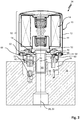
- a filter 10 designed as a replaceable filter cartridge for filtering a fluid, here for example lubricating oil for an internal combustion engine, is shown.
- the filter 10 here comprises a housing part 12, which comprises a cover, with a filter element 14 which is arranged in the housing 12 and which is shown in FIG Fig. 1 is shown highly schematically with a dashed line.
- a support ring 16 is arranged on one end of the filter 10. The support ring 16 surrounds the longitudinal axis 18 of the filter or the coincident filter element longitudinal axis 20 of the filter element 14 in an annular manner.
- the support ring 16 is rotatable about the longitudinal axis 18, ie freely rotatable, mounted on the housing part 12 of the filter 10 and can, for example, be designed as a plastic injection-molded part.
- a closure element 22 is arranged on the support ring 16.
- the closure element 22 extends away from the support ring 16 in an axial direction.
- the closure element 22 can in particular consist of a rubber-elastically deformable material, ie an elastomer.
- a first and a second positioning means 24, 26 are also arranged on the support ring 16.
- the two positioning means 24, 26 are preferably molded onto the support ring 16. Both positioning means 24, 26 extend from the end face away from the support ring 16 in the axial direction.
- the two positioning means 24, 26 are aligned parallel to one another and are arranged at a distance from one another in the circumferential direction of the support ring 16. It should be noted that the second positioning means 26 in the direction of an unscrewing or screwing-in movement of the filter 10, designated by 28, onto a connecting piece of an in Fig. 2
- the filter head shown in more detail is arranged in front of the first positioning means 24. As a result, a gap or receptacle 30 is formed between the two positioning means 24, 26.
- the first positioning means 24 here protrudes beyond the second positioning means 26 in the axial direction. In other words, the second positioning means 26 is with its free axial The end 32 is less spaced from an end face of the filter 10 than the free axial end 32 of the first positioning means 24.
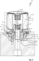
- a filter system 34 for filtering a fluid, in particular fuel or oil, in particular lubricating oil for the internal combustion engine of a motor vehicle (not shown) is shown.
- the filter system 34 comprises a filter 10 according to FIG Fig. 1 and a filter head 36 on which the filter 10 with the filter element 14 arranged therein is to be mounted.
- the filter head 36 is in Fig. 2 shown in a highly schematic manner and has an inlet channel 38 on the raw side, only partially shown, for the fluid to be filtered and an outlet channel 40 arranged on the clean side for the filtered fluid.
- a bottom-side idle channel, labeled 42 , of the filter head 36 is used to drain fluid contained in the filter 10 when the filter 10 is replaced and - following the force of gravity - to divert it in a controlled manner via the filter head 36.
- the idle channel 42 can be fluidically connected, for example, to an oil pan or a fuel tank (not shown).
- the idle channel 42 is closed in a fluid-tight manner by the closure element 22 of the replaceable filter cartridge fastened to the support ring 16.
- the fluid can be pumped through the filter 10 during filter operation and at the same time an undesired outflow of the fluid via the idle channel 42 can be prevented.
- the filter element 14 has a filter medium 44 which surrounds the filter element longitudinal axis 20 in an annular manner.
- the filter element 14 is therefore designed as a so-called round filter element.
- the filter medium 44 can be folded in a star shape in order to obtain the largest possible functional filter surface.
- the filter medium 44 can be arranged held between two end disks of the filter element 14. Other designs of the filter element 14 are easily conceivable.
- the housing part 12 of the filter 10 comprises a cover with a first, internally arranged cover section 46 with a central flow opening and a second, externally arranged cover section 48.
- the second outer cover section 48 is here fluid-tightly connected to the pot-shaped housing section 50 of the housing part 12, for example crimped or welded.
- the first cover section 46 of the housing part 12 has an (internal) thread 52 , via which the filter 10 can be screwed into an (external) thread 54 of a connecting piece 56 of the filter head 36.
- a circumferential sealing ring 58 is arranged on the front side of the housing part 12.
- the sealing ring 58 can according to Fig. 2 have a sealing lip 60 for circumferentially sealing contact with the filter head 36.
- the second cover section 48 can in particular have a seal retaining ring 68 for the sealing ring 58.
- the seal retaining ring 68 is positively connected to the housing part 12 of the filter, in particular crimped or welded.
- the support ring 16 can be hooked to the housing part 12 for the purpose of simple and inexpensive assembly.
- the support ring 16 has one or more hook elements 62 on the filter element side.
- the hook elements 62 here engage behind the second cover section 48, for example.
- a different type of rotatable fastening of the support ring 16 on the housing part 12 of the replaceable filter cartridge 10 is conceivable.
- the filter head 36 has a stop element 64 arranged at the bottom, which serves as a rotary stop for the support ring 16.
- the stop element 64 can according to Fig. 2 in particular extend away from the bottom portion 66 of the filter head 36 in an axial direction.
- the filter head 36 can be made of metal, for example aluminum.
- the stop element 64 can be molded onto the filter head 36 or else it can be designed as a separate component from the filter head 36. In the latter case, the stop element 64 can in particular consist of plastic.
- the support ring 16 When the filter 10 is screwed into the external thread 54 of the filter head 36, the support ring 16 is initially moved together with the filter 10 in the screwing-in direction 28.
- the mutual thread engagement of the filter 10 and the filter head 36 results in a feed movement of the filter 10 axially in the direction of the idle channel 42 or the stop element 64 of the filter head 36 Fig. 2
- the shown mounting state of the filter on the filter head 36 are the two positioning means 24, 26 of the support ring 16 is still axially spaced from the stop element 64.
- the stop element 64 does not yet extend into a rotational path (not shown) of the first positioning means 24 or the second positioning means 26 of the support ring 16.
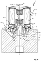
- Fig. 3 is the filter system 10 compared to a Fig. 2 shown later assembly time.
- the filter 10 is screwed further onto the connecting piece 56 of the filter head 36.
- the first positioning means 24 of the support ring 16 has almost reached the stop element 64 in the axial direction.
- the first positioning aid 24 of the support ring 16 is hit against the stop element 64 and thereby the support ring 16 is locked in a predetermined rotational position relative to the filter head 36 with the closure element 22 axially aligned with the drainage channel. This prevents the support ring 16 from rotating further along with the filter 10 in the screwing-in direction 28.
- the closure element 22 is arranged in its sealing seat on the filter head 36.
- the closure element 22 rests against a wall area of the bottom section 66 of the filter head 36 delimiting the idle channel 42 on the circumferential side in a sealing manner in the axial direction.
- the closure element 22 is therefore designed as an axial sealing element.
- the sealing ring 58 of the housing part 12 of the replaceable filter cartridge rests on the filter head 36 in a circumferential, sealing manner.
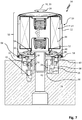
- FIG. 5 Another filter system 34 is shown which differs from that described above in connection with FIGS Figures 2 to 4
- the filter system 34 explained essentially differs in that the closure element 22 is designed as a closure plug that can be introduced into the idle channel 42 of the filter head 36.
- the closure element 22 is therefore designed as a radial sealing element.
- the closure element 22 is preferably made of an elastomer.
- the sectional view in Fig. 5 is selected in such a way that the second positioning means 26 can also be clearly seen.
- the filter 10 is still in its specified (operational) mounting position on the filter head 36 arranged.
- the sealing plug extends into the idle channel 42 in a sealing manner.
- the second positioning means 26 can rest against the stop element 64 in the circumferential direction of the support ring 16.
- the stop element 64 thus extends into the receptacle 30 formed between the two positioning means 24, 26 of the support ring 16 ( Fig. 1 ) into it.
- the second stop element prevents the support ring 16 from rotating with the housing part 12.
- the support ring 16 can be moved out of the idle channel 42 in a strictly axial direction by means of an axial movement of the filter 10 derived from the unscrewing or unscrewing movement of the filter with its sealing plug, as shown in FIG Fig. 6 is shown by way of example. Undesired transverse loading of the closure element 22 is thereby reliably prevented. The risk of parts of the closure element 22 or the entire closure element 22 tearing off from the support ring 16 is thus minimized.
- the support ring 16 can rotate with the filter 10 counter to the screwing-in direction 28.
- the second positioning means 26 and the stop element 64 as well as the closure element 22 and the idle channel 42 are coordinated in terms of their spatial arrangement or dimensions in such a way that a rotational release of the support ring 16 counter to the screwing-in direction 28 is only possible when the closure element is out of the idle channel is fully disengaged in the axial direction, as shown in Fig. 7 is shown.
- the filter 10 can also be designed as a conventional filter insert (without housing part 12) which can be arranged interchangeably in a filter housing having a housing part 12 and a filter head 36.
- the housing part 12 is designed as a filter housing cover in this case and is used to close the filter head 36, which can be clearly described as a cup-shaped design, which means that the filter head 36 has a fluid collection space that is connected to the drainage channel.
- the housing part 12 can be screwed into a thread of the filter head 36.
- the filter 10 is coupled in a rotationally fixed manner to the housing part 12, in particular latched to it or held thereon with a friction fit.
- the filter 10 can in this embodiment in one of the in the Figures 1 to 7
- the filter element 14 shown may be designed in a corresponding manner.
- the support ring 16 can be rotatably attached to an end disk or to a support tube of the filter 10.
Description
Die Erfindung betrifft ein Filtersystem für ein zu filterndes Flüssigmedium, insbesondere Kraftstoff oder Öl, insbesondere Schmieröl, insbesondere für den Verbrennungsmotor eines Kraftfahrzeugs. Das Filtersystem umfasst einen Filterkopf mit einem bodenseitigen Leerlaufkanal für das Fluid und mit einem Anschlagelement sowie einen Filter, der mittels einer um seine Längsachse gerichteten Einschraubbewegung am Filterkopf montierbar ist. Der Filter weist einenends einen Tragring auf, der am Filter relativ zur Längsachse rotierbar befestigt ist, wobei der Tragring ein exzentrisch angeordnetes Verschlusselement für den Leerlaufkanal und ein erstes Positioniermittel aufweist, das mittels der Einschraubbewegung gegen das Anschlagelement des Filterkopfs führbar ist, um den Tragring relativ zum Filterkopf in einer vorgegebenen Drehposition mit zum Leerlaufkanal axial fluchtend angeordnetem Verschlusselement zu positionieren, so dass das Verschlusselement durch eine aus der Einschraubbewegung abgeleitete Axialbewegung des Filters in seinen den Leerlaufkanal verschließenden Dichtsitz am Filterkopf überführbar ist.The invention relates to a filter system for a liquid medium to be filtered, in particular fuel or oil, in particular lubricating oil, in particular for the internal combustion engine of a motor vehicle. The filter system comprises a filter head with an idle channel at the bottom for the fluid and with a stop element as well as a filter which can be mounted on the filter head by means of a screwing-in movement directed about its longitudinal axis. The filter has at one end a support ring which is rotatably attached to the filter relative to the longitudinal axis, the support ring having an eccentrically arranged closure element for the idle channel and a first positioning means that can be guided by means of the screwing-in movement against the stop element of the filter head relative to the support ring to position the filter head in a predetermined rotational position with the closure element axially aligned with the idle channel, so that the closure element can be transferred into its sealing seat on the filter head that closes the idle channel by an axial movement of the filter derived from the screwing-in movement.
Ein eingangs genanntes Filtersystem ist beispielsweise aus der
Dokument
Es ist deshalb die Aufgabe der Erfindung, ein eingangs genanntes Filtersystem und einen Filter für ein solches Filtersystem anzugeben, die bei unverändert einfacher Handhabung einen verbesserten Schutz des Verschlusselements gegenüber Beschädigungen bieten.It is therefore the object of the invention to specify a filter system mentioned at the beginning and a filter for such a filter system which offer improved protection of the closure element against damage with unchanged ease of handling.
Die das Filtersystem betreffende Aufgabe wird durch ein Filtersystem mit den in Anspruch 1 angegebenen Merkmalen gelöst. Der erfindungsgemäße Filter weist die in Anspruch 10 angegebenen Merkmale auf und das erfindungsgemäße Verfahren weist die in Anspruch 14 angegebenen Merkmale auf.The problem relating to the filter system is achieved by a filter system with the features specified in
Bei dem Filtersystem weist der Tragring des Filters erfindungsgemäß ein zweites Positioniermittel auf, durch das der Tragring bei einer der Einschraubbewegung entgegen gerichteten Ausschraubbewegung des Filters relativ zum Filterkopf zum Lösen des Verschlusselements aus seinem Dichtsitz am Filterkopf drehfixiert gehalten ist, so dass das Verschlusselement nur in axialer Richtung aus seinem Dichtsitz herausbewegbar ist. Durch das zweite Positioniermittel ist somit eine rotatorische Verstellung des Tragrings um die Längsachse des Filters bei einer der Einschraubbewegung entgegen gerichteten Ausschraubbewegung des Filters blockiert. Das zweite Positioniermittel kann sich dabei insbesondere an dem eingangs genannten Anschlagelement des Filterkopfs oder auch an einem von dem Anschlagelement beabstandet angeordneten Drehanschlag abstützen und dadurch (zunächst) ein unerwünschtes Mitdrehen des Tragrings mit dem Filter verhindern. Durch ein aus der Ausschraubbewegung abgeleitetes axiales Wegbewegen des Filters vom Filterkopf kann das Verschlusselement axial, insbesondere streng axial, aus seinem Dichtsitz herausbewegt und so eine übermäßige Querbelastung des Verschlusselements verhindert werden. Einem Abreißen von Teilen des Verschlusselements bzw. des gesamten Verschlusselements vom Tragring kann dadurch zuverlässig entgegengewirkt werden. Das zweite Positioniermittel bildet für den Tragring bzw. das daran angeordnete Verschlusselement solange einen Drehschutz, bis das Verschlusselement zuverlässig in axialer Richtung aus seinem Dichtsitz befreit und das zweite Positioniermittel in Umfangsrichtung des Tragrings aus seiner Überlappung mit einem dazu korrespondierenden Drehanschlag, insbesondere dem Anschlagelement, des Filterkopfs in axialer Richtung ausgerückt ist. Auch kann das Verschlusselement bei dem erfindungsgemäßen Filtersystem ohne Weiteres als ein Verschlussstopfen ausgebildet sein, der im Dichtsitz zumindest abschnittsweise in den Leerlaufkanal des Filterkopfs hineinragt und so ein besonders zuverlässiges Dichtvermögen bietet. Der Tragring kann konstruktiv einfach und kostengünstig einteilig ausgebildet sein. DerTragring kann auch mehrteilig, insbesondere in Segmenten, ausgebildet sein, um die Herstellung und Montage zu vereinfachen. Der Tragring weist in einer weiteren Ausführungsform eine in axialer Richtung über das Verschlussmittel und die beiden Positioniermittel hochgezogene Kontur auf, hierdurch kann konstruktiv einfach die Standsicherheit beim Transport zusätzlich optimiert werden; der Tragring kann hierzu einteilig oder mehrteilig, insbesondere in Segmenten, ausgebildet sein.In the filter system, the support ring of the filter has, according to the invention, a second positioning means by which the support ring is held in a rotationally fixed manner when the filter is unscrewed in the opposite direction to the screwing-in movement in order to loosen the closure element from its sealing seat on the filter head, so that the closure element is only axially Direction can be moved out of its sealing seat. The second positioning means thus blocks a rotational adjustment of the support ring about the longitudinal axis of the filter when the filter is unscrewed in the opposite direction to the screwing-in movement. The second positioning means can be supported in particular on the abovementioned stop element of the filter head or also on a rotary stop arranged at a distance from the stop element and thereby (initially) prevent undesired rotation of the support ring with the filter. By axially moving the filter away from the filter head derived from the unscrewing movement, the closure element can be moved axially, in particular strictly axially, out of its sealing seat and thus an excessive transverse loading of the closure element can be prevented. A tearing off of parts of the closure element or of the entire closure element from the support ring can thus be reliably counteracted. The second positioning means forms a rotation protection for the support ring or the closure element arranged on it until the closure element is reliably freed from its sealing seat in the axial direction and the second positioning means in the circumferential direction of the support ring from its overlap with a corresponding rotary stop, in particular the stop element of the The filter head is disengaged in the axial direction. In the case of the filter system according to the invention, the closure element can also easily be designed as a closure plug that is in the sealing seat at least in sections protrudes into the idle channel of the filter head and thus offers a particularly reliable sealing ability. The support ring can be constructed in one piece in a structurally simple and inexpensive manner. The support ring can also be constructed in several parts, in particular in segments, in order to simplify manufacture and assembly. In a further embodiment, the support ring has a contour that is raised in the axial direction over the closure means and the two positioning means; For this purpose, the support ring can be formed in one piece or in several pieces, in particular in segments.
Die beiden Positioniermittel können nach der Erfindung so weit voneinander beabstandet am Tragring angeordnet sein, dass das Anschlagelement des Filterkopfs im Gleitspiel-Formschluss oder mit nur geringem Spiel zwischen den beiden Positioniermitteln einführbar ist. Dadurch kann eine besonders sichere Führung des Tragrings am Anschlagelement in axialer Richtung erreicht werden. Die beiden Positioniermittel sind nach der Erfindung stegförmig ausgeführt.According to the invention, the two positioning means can be arranged so far apart from one another on the support ring that the stop element of the filter head can be inserted with a sliding play form fit or with only little play between the two positioning means. A particularly secure guidance of the support ring on the stop element in the axial direction can thereby be achieved. According to the invention, the two positioning means are designed in the form of webs.
Das zweite Positioniermittel erstreckt sich nach der Erfindung von der Stirnseite des Filters in axialer Richtung vorzugsweise weniger weit weg, als das erste Positioniermittel. Das zweite Positioniermittel ist mit seinem von der Stirnseite des Filters wegweisenden freien axialen Ende somit gegenüber dem dazu korrespondierenden freien axialen Ende des ersten Positioniermittels in Richtung der Stirnseite axial zurückversetzt angeordnet. Beim Montieren des Filters am Filterkopf kann dadurch gewährleistet werden, dass zuerst das erste Positioniermittel am filterkopfseitig angeordneten Anschlagelement anschlägt und nicht etwa das zweite Positioniermittel. Eine weitere Einschraubbewegung des Filters bewirkt bei an dem Anschlagelement anliegendem ersten Positioniermittel sodann eine alleinige axiale Verstellung des Tragrings in Richtung auf den Leerlaufkanal. Das Anschlagelement kann dadurch zwischen den beiden Positioniermitteln eingreifen bzw. zwischen diesen geführt werden. Dadurch kann Montagefehlern vorgebeugt werden.According to the invention, the second positioning means preferably extends less far away from the end face of the filter in the axial direction than the first positioning means. The second positioning means is thus arranged with its free axial end pointing away from the end face of the filter, axially set back in the direction of the end face with respect to the corresponding free axial end of the first positioning means. When the filter is mounted on the filter head, this ensures that the first positioning means strikes the stop element arranged on the filter head side first and not the second positioning means, for example. A further screwing-in movement of the filter then causes only an axial adjustment of the support ring in the direction of the idle channel when the first positioning means is in contact with the stop element. The stop element can thereby engage between the two positioning means or be guided between them. This can prevent assembly errors.
Nach einer alternativen Ausführungsform können sich die Positioniermittel auch vom Tragring in axialer Richtung gleich weit wegerstrecken. Mit anderen Worten können die freien Enden der beiden Anschlagelemente in axialer Richtung auch auf gleicher Höhe angeordnet sein. In diesem Fall sind die beiden Positioniermittel bevorzugt in radialer Richtung zueinander versetzt angeordnet, d. h. von der Längsachse des Filters unterschiedlich weit beabstandet. Das Anschlagmittel bildet in diesem Fall für die Positionierhilfen zwei Anschlagbereiche aus, die in axialer und in radialer Richtung zueinander versetzt angeordnet sind, so dass beim Montieren des (in Einschraubrichtung bewegten) Filters am Filterkopf immer nur bzw. zuerst das erste Positioniermittel am Anschlagelement anschlägt. Die beiden Positioniermittel können in einer weiteren Ausführungsform in einer im Wesentlichen gleichen radialen Position zwischen der äußeren und inneren Umfangskontur des Tragrings angeordnet sein, hierdurch wird konstruktiv einfach sichergestellt, dass nur der für den vorbestimmten Einsatz passende Filter verwendet wird.According to an alternative embodiment, the positioning means can also extend equally far away from the support ring in the axial direction. In other words, the free ends of the two stop elements can also be arranged at the same height in the axial direction. In this case, the two positioning means are preferably radial Arranged offset from one another in the direction, that is to say at different distances from the longitudinal axis of the filter. In this case, the stop means forms two stop areas for the positioning aids, which are offset from one another in the axial and radial directions, so that when the filter (moved in the screwing direction) is mounted on the filter head, only or first the first positioning means strikes the stop element. In a further embodiment, the two positioning means can be arranged in a substantially identical radial position between the outer and inner circumferential contour of the support ring; this ensures in a structurally simple manner that only the filter suitable for the predetermined application is used.
Der Anschlag für die beiden Positioniermittel im Filterkopf kann vorzugsweise mit einer größeren axialen Erstreckung von der Stirnseite des Filterkopfs weg als die Oberkante des Ablaufkanals ausgebildet sein.The stop for the two positioning means in the filter head can preferably be designed with a larger axial extension away from the end face of the filter head than the upper edge of the drainage channel.
Erfindungsgemäß können die beiden Positioniermittel am Tragring stirnseitig und/oder umfangsseitig angeordnet sein. Sind die Positioniermittel umfangsseitig am Tragring angeformt, so kann dadurch vereinfacht eine mechanisch stabile Anbindung der Positioniermittel am Tragring erreicht werden.According to the invention, the two positioning means can be arranged on the end face and / or circumferentially on the support ring. If the positioning means are formed on the circumference of the support ring, a mechanically stable connection of the positioning means on the support ring can thereby be achieved in a simplified manner.
Das Verschlusselement kann sich nach der Erfindung insbesondere in axialer Richtung von dem Tragring wegerstrecken.According to the invention, the closure element can in particular extend away from the support ring in the axial direction.
Nach einer bevorzugten Ausführungsform der Erfindung ist das Verschlusselement als ein Verschlussstopfen ausgebildet, der zumindest abschnittsweise in axialer Richtung in den Leerlaufkanal eingeführt werden kann. Der Verschlussstopfen dient in diesem Fall zumindest teilweise als ein Radialdichtungselement. Das Verschlusselement kann zusätzlich oder alternativ der Form des Ablaufkanals angepasst sein. In einer Ausführungsform kann das Verschlusselement beispielsweise nierenförmig ausgebildet sein. Nierenförmig bedeutet hierbei, dass das Verschlusselement in der Grundfläche im Wesentlichen rund oder elliptisch ist und eine Vertiefung oder Einbuchtung in der Außenkontur aufweist, so dass sich das Vorzeichen der Krümmungsrichtung der Außenkontur mindestens einmal ändert, wobei die Vertiefung oder Einbuchtung die Grundfläche in zwei, insbesondere im Wesentlichen abgerundete, Bereiche aufteilt. Die Aufteilung kann hierbei symmetrisch oder auch asymmetrisch sein, so dass zwei in der Fläche gleich große Bereiche entstehen oder der erste Bereich eine größere Fläche aufweist als der zweite Bereich. Diese Ausführungsform hat den Vorteil, dass die Positionierungsgenauigkeit konstruktiv einfach sichergestellt werden kann, mit anderen Worten trifft das Dichtmittel konstruktiv einfach sichergestellt den Dichtsitz und deckt diesen sicher ab.According to a preferred embodiment of the invention, the closure element is designed as a closure plug which can be introduced into the idle channel at least in sections in the axial direction. In this case, the sealing plug serves at least partially as a radial sealing element. The closure element can additionally or alternatively be adapted to the shape of the drainage channel. In one embodiment, the closure element can be kidney-shaped, for example. Kidney-shaped here means that the closure element is essentially round or elliptical in the base area and has a depression or indentation in the outer contour, so that the sign of the direction of curvature of the outer contour changes at least once, the depression or indentation dividing the base area in two, in particular essentially rounded, dividing areas. The division can be symmetrical or also be asymmetrical, so that two areas of the same size arise in the area or the first area has a larger area than the second area. This embodiment has the advantage that the positioning accuracy can be ensured in a structurally simple manner, in other words the sealant strikes the sealing seat in a structurally simple manner and reliably covers it.
Das Verschlusselement kann zwecks eines besonders zuverlässigen Dichtvermögens mit einem elastomeren Radial- und/oder einem Axialdichtungselement versehen sein bzw. als ein solches elastomeres Radial- und/oder Axialdichtungselement ausgebildet sein. Dadurch kann eine zuverlässige fluiddichte Abdichtung des Leerlaufkanals gewährleistet werden. Das Verschlusselement kann erfindungsgemäß zusätzlich eine, vorzugsweise als Ringnut, ausgeführte Dichtungshaltestruktur für das vorgenannte Radial- bzw. Axialdichtungselement aufweisen. Dadurch erübrigt sich ein zusätzliches Festkleben bzw. Anschäumen des Dichtungselements am Verschlusselement.The closure element can be provided with an elastomeric radial and / or an axial sealing element or designed as such an elastomeric radial and / or axial sealing element for the purpose of a particularly reliable sealing capability. A reliable, fluid-tight seal of the idle channel can thereby be ensured. According to the invention, the closure element can additionally have a seal holding structure, preferably designed as an annular groove, for the aforementioned radial or axial seal element. This eliminates the need for additional gluing or foaming of the sealing element on the closure element.
Das Verschlusselement kann in weiteren Ausführungsformen zu dem ersten und/oder zu dem zweiten Positioniermittel benachbart angeordnet sein. Die Positioniermittel können beispielsweise auf den Tragring (360°, erster Quadrant α = 0 - 90°; zweiter Quadrant α = 90 - 180°; dritter Quadrant α = 180 - 270°; vierter Quadrant α = 270 - 360°) bezogen in einem Bogenwinkel α zum Verschlusselement beabstandet angeordnet sein und beispielsweise auf den Tragring bezogen können die Positioniermittel dem Verschlusselement gegenüberliegend angeordnet sein. Benachbart im Sinne der Erfindung bedeutet hierbei, dass das Verschlusselement und das erste sowie das zweite Positioniermittel bevorzugt in zwei benachbarten Quadranten des Tragrings, besonders bevorzugt in einem Quadrant des Tragrings, angeordnet sind. Für den Fall, dass das Verschlusselement und die Positioniermittel in zwei benachbarten Quadranten des Tragrings angeordnet sind, kann das Verschlusselement in einem ersten Quadrant des Tragrings angeordnet sein und die Positioniermittel können in einem zweiten Quadrant des Tragrings angeordnet sein. Alternativ können auch das Verschlusselement und das erste oder das zweite Positioniermittel in dem ersten Quadrant des Tragrings angeordnet sein und das jeweils andere Positioniermittel in einem hierzu benachbarten zweiten Quadranten angeordnet sein. Gegenüberliegend bedeutet im Sinne der Erfindung, dass das Verschlusselement auf einem ersten Halbkreissegment des Tragrings angeordnet ist und das erste und das zweite Positioniermittel auf dem zweiten Halbkreissegment des Tragrings angeordnet sind, wobei die Mitte des Verschlusselements und die Mitte des Abstands zwischen den beiden Positioniermitteln bevorzugt den jeweiligen Bezugspunkt bilden und wobei diese Bezugspunkte bevorzugt einander gegenüberliegend angeordnet sind.In further embodiments, the closure element can be arranged adjacent to the first and / or to the second positioning means. The positioning means can, for example, refer to the support ring (360 °, first quadrant α = 0-90 °; second quadrant α = 90-180 °; third quadrant α = 180-270 °; fourth quadrant α = 270-360 °) in one Arc angle α can be arranged at a distance from the closure element and, for example, based on the support ring, the positioning means can be arranged opposite the closure element. In the context of the invention, adjacent means that the closure element and the first and second positioning means are preferably arranged in two adjacent quadrants of the support ring, particularly preferably in one quadrant of the support ring. In the event that the closure element and the positioning means are arranged in two adjacent quadrants of the support ring, the closure element can be arranged in a first quadrant of the support ring and the positioning means can be arranged in a second quadrant of the support ring. Alternatively, the closure element and the first or the second positioning means can also be arranged in the first quadrant of the support ring and the respective other positioning means can be arranged in a second quadrant adjacent thereto. In the context of the invention, opposite means that the closure element is arranged on a first semicircular segment of the support ring and the first and second positioning means are arranged on the second semicircular segment of the support ring are, wherein the center of the closure element and the center of the distance between the two positioning means preferably form the respective reference point and these reference points are preferably arranged opposite one another.
Für eine besonders einfache und störungsarme Montage des Filtersystems kann das zweite Positioniermittel des Tragrings erfindungsgemäß eine stirnseitige Auflaufschräge für das Anschlagelement aufweisen. Dadurch kann bei der Montage des Filters am Filterkopf einem unerwünschten Verkanten des zweiten Positioniermittels an dem Anschlagelement entgegengewirkt werden.For a particularly simple and trouble-free assembly of the filter system, the second positioning means of the support ring can, according to the invention, have an end face slope for the stop element. As a result, undesired tilting of the second positioning means on the stop element can be counteracted when the filter is mounted on the filter head.
Unter fertigungstechnischen Aspekten sind die beiden Positioniermittel vorzugsweise an dem Tragring angeformt. Der Tragring kann dadurch besonders kostengünstig und mit geringen Fertigungstoleranzen im Wege eines Kunststoff-Spritzgussverfahrens erzeugt werden. Dies ist insbesondere bei der Massenfertigung des Filters von Vorteil.From a manufacturing point of view, the two positioning means are preferably molded onto the support ring. As a result, the support ring can be produced in a particularly cost-effective manner and with low manufacturing tolerances by means of a plastic injection molding process. This is particularly advantageous in the case of mass production of the filter.
Der Filter ist erfindungsgemäß als eine Wechselfilterkartusche ausgebildet. Eine Wechselfilterkartusche, auch als Wechselfilter bezeichnet, im Sinne der Anmeldung ist eine nicht zerstörungsfrei offenbare Filterkartusche, diese umfasst ein Gehäuse mit einem Deckel, wobei das Gehäuse insbesondere aus Metall oder Kunststoff ist. In dem Gehäuse ist ein Filterelement angeordnet, insbesondere ein ringförmiges Filterelement. Das Gehäuse weist bevorzugt einen Deckelabschnitt mit einem Einlass, einem Auslass und einem auf dem Deckelabschnitt angeordneten Dichtungssitz auf. Der Auslass ist bevorzugt zentrisch in einem ersten Deckelabschnitt vorgesehen, der Dichtungssitz ist bevorzugt konzentrisch zu dem Auslass auf einem zweiten Deckelabschnitt angeordnet und der im Deckel, insbesondere im zweiten Deckelabschnitt, angeordnete Einlass befindet sich vorzugsweise zwischen dem Auslass und dem Dichtungssitz. Der Auslass umfasst vorzugsweise ein Gewinde.According to the invention, the filter is designed as a replaceable filter cartridge. A replaceable filter cartridge, also referred to as a replaceable filter, in the sense of the application is a filter cartridge that cannot be opened non-destructively; it comprises a housing with a cover, the housing being in particular made of metal or plastic. A filter element, in particular an annular filter element, is arranged in the housing. The housing preferably has a cover section with an inlet, an outlet and a sealing seat arranged on the cover section. The outlet is preferably provided centrally in a first cover section, the seal seat is preferably arranged concentrically to the outlet on a second cover section and the inlet arranged in the cover, in particular in the second cover section, is preferably located between the outlet and the seal seat. The outlet preferably comprises a thread.
Das den Deckel bildende Gehäuseteil des Filters umfasst in einer weiteren Ausführungsform einen ersten innenliegend angeordneten Deckelabschnitt mit einer zentralen Strömungsöffnung und einen zweiten außenliegend angeordneten Deckelabschnitt. Der zweite außenliegende Deckelabschnitt ist hier mit dem topfförmigen Gehäuseabschnitt des Gehäuseteils fluiddicht verbunden, beispielsweise verbördelt oder verschweißt. Der erste Deckelabschnitt des Gehäuseteils weist bevorzugt ein (Innen-)Gewinde auf, über das der erfindungsgemäße Filter in ein (Außen-)Gewinde eines Anschlussstutzens des Filterkopfs einschraubbar ist. Am Gehäuseteil kann in einer weiteren Ausführungsform stirnseitig ein umlaufender Dichtungsring angeordnet sein. Der Dichtungsring kann zusätzlich eine Dichtlippe zur umlaufend dichtenden Anlage am Filterkopf aufweisen. In weiteren Ausführungsformen kann ein Dichtungshaltering für den Dichtungsring vorgesehen sein, wobei der Dichtungshaltering einen Teil des zweiten Deckelabschnitts bildet. Der Dichtungshaltering ist in einer bevorzugten Ausführungsform formschlüssig mit dem Gehäuseteil des Filters verbunden, insbesondere gebördelt oder verschweißt.In a further embodiment, the housing part of the filter which forms the cover comprises a first cover section arranged on the inside with a central flow opening and a second cover section arranged on the outside. The second outer cover section is here connected in a fluid-tight manner to the cup-shaped housing section of the housing part, for example crimped or welded. The first cover section of the housing part preferably has an (internal) thread over that the filter according to the invention can be screwed into an (external) thread of a connecting piece of the filter head. In a further embodiment, a circumferential sealing ring can be arranged on the front side of the housing part. The sealing ring can also have a sealing lip for circumferentially sealing contact with the filter head. In further embodiments, a seal retaining ring can be provided for the sealing ring, the seal retaining ring forming part of the second cover section. In a preferred embodiment, the seal retaining ring is positively connected to the housing part of the filter, in particular flanged or welded.
Die erfindungsgemäße Wechselfilterkartusche ist mittels einer um ihre Längsachse gerichtete Einschraubbewegung am Filterkopf montierbar, wobei die Wechselfilterkartusche einenends einen Tragring aufweist, der am insbesondere topfförmigen Gehäuseteil der Wechselfilterkartusche relativ zur Längsachse der Wechselfilterkartusche rotierbar befestigt ist, wobei der Tragring ein exzentrisch angeordnetes Verschlusselement für den Leerlaufkanal und ein erstes stegförmiges Positioniermittel aufweist, das mittels der Einschraubbewegung gegen das Anschlagelement des Filterkopfs führbar ist, um den Tragring relativ zum Filterkopf in einer vorgegebenen Drehposition mit zum Leerlaufkanal axial fluchtend angeordnetem Verschlusselement zu positionieren, so dass das Verschlusselement durch eine aus der Einschraubbewegung abgeleitete Axialbewegung des Filters in seinen den Leerlaufkanal verschließenden Dichtsitz am Filterkopf überführbar ist, wobei der Tragring ein zweites stegförmiges Positioniermittel aufweist, durch das der Tragring bei einer der Einschraubbewegung entgegengerichteten Ausschraubbewegung des Filters zum Lösen des Verschlusselements aus seinem Dichtsitz am Filterkopf durch Anlage am Anschlagelement (64) drehfixiert gehalten werden kann, so dass das Verschlusselement allein in axialer Richtung aus seinem Dichtsitz herausbewegbar ist. Das zweite Positioniermittel ist am Tragring derart ausgebildet, dass der Tragring durch Anlage des zweiten Positioniermittels am Anschlagelement relativ zum Filterkopf drehfixiert gehalten werden kann.The replaceable filter cartridge according to the invention can be mounted on the filter head by means of a screwing-in movement directed around its longitudinal axis, the replaceable filter cartridge having a support ring at one end, which is fastened to the particularly cup-shaped housing part of the replaceable filter cartridge so as to be rotatable relative to the longitudinal axis of the replaceable filter cartridge, the support ring having an eccentrically arranged closure element for the idle channel and has a first web-shaped positioning means that can be guided by means of the screwing-in movement against the stop element of the filter head in order to position the support ring relative to the filter head in a predetermined rotational position with the closure element axially aligned with the idle channel, so that the closure element is caused by an axial movement derived from the screwing-in movement Filter can be transferred into its sealing seat on the filter head that closes the idle channel, the support ring having a second web-shaped positioning means by means of which the support ring can be held in a rotationally fixed manner when the filter is unscrewed in the opposite direction to the screwing-in movement in order to loosen the closure element from its sealing seat on the filter head by resting on the stop element (64), so that the closure element can only be moved out of its sealing seat in the axial direction. The second positioning means is designed on the support ring in such a way that the support ring can be held in a rotationally fixed manner relative to the filter head by the second positioning means resting against the stop element.
In einer weiteren Ausführungsform des Filters erstreckt sich zumindest eines der beiden Positioniermittel, bevorzugt beide Positioniermittel, in einer radialen Richtung vom Tragring weg. Die beiden Positioniermittel sind besonders bevorzugt entweder innerhalb des Tragringumfangs oder außerhalb des Tragringumfangs angeordnet. Das erste und/oder das zweite Positioniermittel erstreckt sich in einer weiteren Ausführungsform in axialer Richtung über das Verschlusselement hinaus von der Stirnseite des Filters weg, wobei das erste Positioniermittel sich weiter erstreckt als das zweite Positioniermittel.In a further embodiment of the filter, at least one of the two positioning means, preferably both positioning means, extends in a radial direction away from the support ring. The two positioning means are particularly preferably arranged either inside the support ring circumference or outside the support ring circumference. The first and / or the second positioning means extends in a further embodiment in the axial direction beyond the closure element away from the end face of the filter, the first positioning means extending further than the second positioning means.
In einer bevorzugten Ausführungsform ist rohseitig zusätzlich eine Rücklaufsperrmembran im Gehäuse des Filters vorgesehen, welche in der Einbausituation auf der Rohseite des Filters angeordnet ist und ein Rückströmen des Flüssigmediums, beispielsweise eines Öls, verhindert.In a preferred embodiment, a non-return membrane is additionally provided on the raw side in the housing of the filter, which is arranged on the raw side of the filter in the installation situation and prevents the liquid medium, for example an oil, from flowing back.
Weitere Merkmale des erfindungsgemäßen Filters sind oben im Rahmen der Beschreibung des erfindungsgemäßen Filtersystems beschrieben.Further features of the filter according to the invention are described above in the context of the description of the filter system according to the invention.
Derartige Wechselfilterkartuschen weisen somit ein integrales Gehäuseteil auf, in dem ein Filterelement angeordnet ist. Die Wechselfilterkartuschen sind besonders einfach und bequem zu handhaben und werden zumeist im sogenannten Hauptstrom eingesetzt, bei dem der gesamte Fluidstrom den Filter durchströmt. Der Tragring kann in diesem Fall insbesondere an einem Deckelabschnitt des Gehäuseteils der Wechselfilterkartusche rotierbar befestigt sein. Unter konstruktiven wie auch fertigungstechnischen Gesichtspunkten ist der Tragring vorzugsweise mit dem Filter, insbesondere dessen Deckelabschnitt, verhakt, also mittels eines Hinterschnitts gehalten bzw. verbunden.Such replaceable filter cartridges thus have an integral housing part in which a filter element is arranged. The replaceable filter cartridges are particularly easy and convenient to use and are mostly used in what is known as the main flow, in which the entire fluid flow flows through the filter. In this case, the support ring can in particular be rotatably attached to a cover section of the housing part of the replaceable filter cartridge. From a structural and manufacturing point of view, the support ring is preferably hooked to the filter, in particular its cover section, that is to say held or connected by means of an undercut.
Nach einer alternativen Ausführungsform kann der Filter auch als ein in einem Filtergehäuse austauschbar anzuordnender Filtereinsatz ausgeführt sein. Dies ermöglicht einen besonders kostengünstigen Austausch des Filters. Das Filtersystem weist in diesem Falle ein Filtergehäuse mit dem Filterkopf und einem als Gehäusedeckel ausgeführten Gehäuseteil auf, das in das Gewinde des Filterkopfs einschraubbar ist. Der Filterkopf ist vorzugsweise topfartig bzw. als ein mit dem Gehäusedeckel verschließbarer Gehäusetopf ausgeführt, der der Aufnahme des Filters dient. Bei dieser Bauart ist der Filter an dem als Gehäusedeckel ausgebildeten Gehäuseteil vorteilhaft drehfest und in axialer Richtung lagefixiert gehalten. Dies kann beispielsweise dadurch erreicht werden, dass der Filter mit dem Gehäusedeckel verrastet ist. Alternativ kann der Filter auch im Reibschluss am Gehäuseteil gehalten angeordnet sein. Insgesamt kann dadurch beim Einschrauben des Gehäusedeckels in das Gewinde des Filterkopfs und auch beim Abschrauben des Gehäusedeckels vom Filterkopf ein Mitdrehen des Filters gewährleistet werden.According to an alternative embodiment, the filter can also be designed as a filter insert to be exchangeably arranged in a filter housing. This enables a particularly cost-effective replacement of the filter. In this case, the filter system has a filter housing with the filter head and a housing part designed as a housing cover, which can be screwed into the thread of the filter head. The filter head is preferably designed in the form of a pot or as a housing pot which can be closed with the housing cover and which is used to hold the filter. In this type of construction, the filter is advantageously held in a rotationally fixed manner and fixed in position in the axial direction on the housing part designed as a housing cover. This can be achieved, for example, in that the filter is locked to the housing cover. Alternatively, the filter can also be arranged held in a frictional connection on the housing part. Overall, this can result in Screwing the housing cover into the thread of the filter head and also when unscrewing the housing cover from the filter head ensures that the filter rotates at the same time.
Ist der Filter als ein herkömmlicher Filtereinsatz für ein öffenbares Filtergehäuse mit dem Filterkopf und einem Gehäusedeckel ausgebildet, so kann der Tragring nach der Erfindung an einer Endscheibe oder einem Stützrohr des Filters angeordnet, insbesondere verrastet sein, um eine einfache und kostengünstige Fertigung des Filters zu ermöglichen.If the filter is designed as a conventional filter insert for an openable filter housing with the filter head and a housing cover, the support ring according to the invention can be arranged, in particular latched, on an end plate or a support tube of the filter in order to enable simple and inexpensive manufacture of the filter .
Der erfindungsgemäße Filter für ein vorstehend erläutertes Filtersystem ist erfindungsgemäß als eine Wechselfilterkartusche ausgeführt. Der Filter zeichnet sich durch eine besonders einfache und sichere Handhabung aus.The filter according to the invention for a filter system explained above is designed according to the invention as a replaceable filter cartridge. The filter is particularly easy and safe to use.
Das erfindungsgemäße Verfahren zum Einsetzen oder Wechseln eines Filters eines erfindungsgemäßen Filtersystems umfasst die Schritte:
- Aufsetzen einer Wechselfilterkartusche, umfassend ein in einem Gehäuse der Wechselfilterkartusche angeordnetes Filterelement auf einen Filterkopf,
- Montieren der Wechselfilterkartusche mittels einer um eine Längsachse gerichteten Einschraubbewegung am Filterkopf, wobei der Filter einenends einen Tragring aufweist, der am Gehäuseteil der Wechselfilterkartusche relativ zur Längsachse der Wechselfilterkartusche rotierbar befestigt ist, wobei der Tragring ein exzentrisch angeordnetes Verschlusselement für den Leerlaufkanal und ein erstes stegförmiges Positioniermittel aufweist, das mittels der Einschraubbewegung gegen das Anschlagelement des Filterkopfs führbar ist, Positionierung des Tragrings relativ zum Filterkopf in einer vorgegebenen Drehposition mit zum Leerlaufkanal axial fluchtend angeordnetem Verschlusselement,
- Überführen des Verschlusselements durch eine aus der Einschraubbewegung abgeleitete Axialbewegung der Wechselfilterkartusche in ihren den Leerlaufkanal verschließenden Dichtsitz am Filterkopf, wobei der Tragring ein zweites stegförmiges Positioniermittel aufweist, durch das der Tragring bei einer der Einschraubbewegung entgegengerichteten Ausschraubbewegung des Filters zum Lösen des Verschlusselements aus seinem Dichtsitz am Filterkopf am Anschlagelement (64) anliegend drehfixiert gehalten ist, so dass das Verschlusselement allein in axialer Richtung aus seinem Dichtsitz herausbewegbar ist.
- Attaching a replaceable filter cartridge, comprising a filter element arranged in a housing of the replaceable filter cartridge, onto a filter head,
- Mounting the replaceable filter cartridge by means of a screwing-in movement directed around a longitudinal axis on the filter head, the filter having a support ring at one end which is rotatably fastened to the housing part of the replaceable filter cartridge relative to the longitudinal axis of the replaceable filter cartridge, the support ring having an eccentrically arranged closure element for the idle channel and a first web-shaped positioning means which can be guided against the stop element of the filter head by means of the screwing-in movement, positioning of the support ring relative to the filter head in a predetermined rotational position with the closure element axially aligned with the idle channel,
- Transfer of the closure element by an axial movement of the replaceable filter cartridge derived from the screwing-in movement into its sealing seat on the filter head that closes the idle channel, the support ring having a second web-shaped positioning means by which the support ring, when the screwing-in movement is unscrewing the filter in the opposite direction, to loosen the closure element from its sealing seat on the The filter head is held in a rotationally fixed manner resting against the stop element (64), so that the closure element can only be moved out of its sealing seat in the axial direction.
Ein Wechseln des erfindungsgemäßen Filters kann zusätzlich als vorgelagerten Schritt das Lösen und Entfernen eines auszutauschenden Filters durch eine der Einschraubbewegung entgegengerichtete Ausschraubbewegung umfassen, wobei der Tragring während des Lösens des Verschlusselements aus seinem Dichtungssitz am Filterkopf drehfixiert gehalten ist, so dass das Verschlusselement allein in axialer Richtung aus dem Dichtsitz herausbewegbar ist.Changing the filter according to the invention can also include, as a preceding step, the loosening and removal of a filter to be exchanged by an unscrewing movement in the opposite direction to the screwing-in movement, the support ring being held in a rotationally fixed manner during the loosening of the closure element from its sealing seat on the filter head, so that the closure element only in the axial direction can be moved out of the sealing seat.
Nachstehend wird die Erfindung anhand zweier in der Zeichnung wiedergegebener Ausführungsbeispiele näher erläutert.The invention is explained in more detail below with reference to two exemplary embodiments shown in the drawing.
In der Zeichnung zeigen
- Fig. 1
- einen als Wechselfilterkartusche ausgeführten Filter mit einem stirnseitig angeordneten Tragring mit einem Verschlusselement sowie zwei Positioniermitteln, in einer perspektivischen Ansicht;
- Fig. 2
- ein Filtersystem mit einem Filter gemäß
Fig. 1 und mit einem Filterkopf, der einen durch das Verschlusselement des Filters zu verschließenden Leerlaufkanal aufweist, während der Montage des Filters am Filterkopf, in einer Schnittdarstellung; - Fig. 3
- das Filtersystem gemäß
Fig. 2 zu einem späteren Montagezeitpunkt; - Fig. 4
- das Filtersystem gemäß
Fig. 2 zu einem gegenüberFig. 3 nochmals späteren Montagezeitpunkt; - Fig. 5
- ein weiteres Filtersystem mit einem in seiner vorgegebenen Montageposition am Filterkopf angeordneten Filter;
- Fig. 6
- das Filtersystem gemäß
Fig. 5 beim Abschrauben des Filters vom Filterkopf, wobei das zweite Positioniermittel an einem Anschlagelement des Filterkopfs anliegt und so ein Mitdrehen des Tragrings mit Filter entgegen der Einschraubrichtung verhindert; und - Fig. 7
- das Filtersystem aus
Fig. 5 zu einem Demontagezeitpunkt, bei dem das filterkopffest angeordnete Anschlagelement und die Positioniermittel des Tragrings des Filters außer Eingriff gebracht sind.
- Fig. 1
- a filter designed as a replaceable filter cartridge with a support ring arranged at the end with a closure element and two positioning means, in a perspective view;
- Fig. 2
- a filter system with a filter according to
Fig. 1 and with a filter head, which has an idle channel to be closed by the closure element of the filter, during the assembly of the filter on the filter head, in a sectional view; - Fig. 3
- the filter system according to
Fig. 2 at a later assembly date; - Fig. 4
- the filter system according to
Fig. 2 to one oppositeFig. 3 later assembly time again; - Fig. 5
- a further filter system with a filter arranged in its predetermined mounting position on the filter head;
- Fig. 6
- the filter system according to
Fig. 5 when unscrewing the filter from the filter head, the second positioning means resting against a stop element of the filter head and thus preventing the support ring with the filter from rotating counter to the screwing direction; and - Fig. 7
- the filter system off
Fig. 5 at a dismantling time at which the stop element fixed to the filter head and the positioning means of the support ring of the filter are disengaged.
In
In
Der Filterkopf 36 ist in
Wie aus der Schnittdarstellung des Filtersystems 34 in
Das Gehäuseteil 12 des Filters 10 umfasst einen Deckel mit einem ersten, innenliegend angeordneten Deckelabschnitt 46 mit einer zentralen Strömungsöffnung und einen zweiten, außenliegend angeordneten Deckelabschnitt 48. Der zweite außenliegende Deckelabschnitt 48 ist hier mit dem topfförmigen Gehäuseabschnitt 50 des Gehäuseteils 12 fluiddicht verbunden, beispielsweise verbördelt oder verschweißt. Der erste Deckelabschnitt 46 des Gehäuseteils 12 weist ein (Innen-)Gewinde 52 auf, über das der Filter 10 in ein (Außen-)Gewinde 54 eines Anschlussstutzens 56 des Filterkopfs 36 einschraubbar ist. Am Gehäuseteil 12 ist stirnseitig ein umlaufender Dichtungsring 58 angeordnet. Der Dichtungsring 58 kann gemäß
Der Tragring 16 kann zwecks einer einfachen und kostengünstigen Montage mit dem Gehäuseteil 12 verhakt sein. Der Tragring 16 weist in diesem Fall filterelementseitig ein oder mehrere Hakenelemente 62 auf. Die Hakenelemente 62 hintergreifen hier beispielhaft den zweiten Deckelabschnitt 48. Eine andersgeartete rotierbare Befestigung des Tragrings 16 am Gehäuseteil 12 der Wechselfilterkartusche 10 ist vorstellbar.The
Der Filterkopf 36 weist ein bodenseitig angeordnetes Anschlagelement 64 auf, das für den Tragring 16 als ein Drehanschlag dient. Das Anschlagelement 64 kann sich gemäß
Beim Einschrauben des Filters 10 in das Außengewinde 54 des Filterkopfs 36 wird der Tragring 16 zunächst gemeinsam mit dem Filter 10 in Einschraubrichtung 28 mitbewegt. Aus dem gegenseitigen Gewindeeingriff des Filters 10 und des Filterkopfs 36 resultiert dabei eine Vorschubbewegung des Filters 10 axial in Richtung des Leerlaufkanals 42 bzw. des Anschlagelements 64 des Filterkopfs 36. In dem in
In
In
Wird der Filter 10 entgegen der Einschraubrichtung 28 relativ zum Filterkopf 36 um die Längsachse 18 gedreht, um den Filter 10 vom Filterkopf 36 zu lösen, ist durch das zweite Anschlagelement ein Mitdrehen des Tragrings 16 mit dem Gehäuseteil 12 unterbunden. Der Tragring 16 kann mittels einer aus der Aus- oder Abschraubbewegung des Filters abgeleiteten axialen Bewegung des Filters 10 mit seinem Verschlussstopfen aus dem Leerlaufkanal 42 in streng axialer Richtung herausbewegt werden, wie dies in
Sobald das kürzere zweite Positioniermittel 26 und das Anschlagelement 64 in Umfangsrichtung des Tragrings 16 einander nicht mehr überdecken, ist ein Mitdrehen des Tragrings 16 mit dem Filter 10 entgegen der Einschraubrichtung 28 ermöglicht. Das zweite Positioniermittel 26 und das Anschlagelement 64 sowie das Verschlusselement 22 und der Leerlaufkanal 42 sind in ihrer räumlichen Anordnung bzw. Bemaßung derart aufeinander abgestimmt, dass eine rotatorische Freigabe des Tragrings 16 entgegen der Einschraubrichtung 28 erst dann ermöglicht ist, wenn das Verschlusselement aus dem Leerlaufkanal in axialer Richtung vollständig ausgerückt ist, wie dies in
Zu beachten ist, dass der Filter 10 nach einer in der Zeichnung nicht dargestellten Ausführungsform auch als ein herkömmlicher Filtereinsatz (ohne Gehäuseteil 12) ausgeführt sein kann, der in einem ein Gehäuseteil 12 und einen Filterkopf 36 aufweisenden Filtergehäuse austauschbar anordenbar ist. Das Gehäuseteil 12 ist in diesem Fall als Filtergehäusedeckel ausgeführt und dient dem Verschließen des anschaulich als topfförmig ausgeführt beschreibbaren Filterkopfs 36, wobei damit gemeint ist, dass der Filterkopf 36 einen Fluidsammelraum aufweist, der mit dem Ablaufkanal verbunden ist. Das Gehäuseteil 12 ist in ein Gewinde des Filterkopfs 36 einschraubbar. Der Filter 10 ist mit dem Gehäuseteil 12 drehfest verkoppelt, insbesondere mit diesem verrastet oder an diesem reibschlüssig gehalten. Der Filter 10 kann bei dieser Ausführungsform in einer dem in den
Claims (14)
- Filter system (34) for a liquid medium to be filtered, in particular for fuel or oil, in particular for lubricating oil, in particular for the internal combustion engine of a motor vehicle, comprising:- a filter head (36) having a bottom-sided drainage channel (42) for the fluid and having a stop element (64);- a filter (10) designed as replaceable filter cartridge, comprising a filter element (14) disposed in a housing (12) of the replaceable filter cartridge (10), wherein the replaceable filter cartridge (10) is mountable on the filter head (36) by means of a screwing-in movement (28) oriented around its longitudinal axis (18), wherein the replaceable filter cartridge (10) features at one end a supporting ring (16), which is rotatably attached to the housing component (12), in particular to the cover (46, 48) of the housing component (12), of the replaceable filter cartridge (10) relative to the longitudinal axis (18) of the replaceable filter cartridge (10), whereincharacterized in that the supporting ring (16) features a second positioning means (26) for contacting the stop element (64) by means of which the supporting ring (16) is held in a rotationally fixed manner on the filter head (36) during an unscrewing movement of the filter (10) in the direction opposite to the screwing-in movement (28) for releasing the closure member (22) from its sealing seat, so that the closure member (22) can be moved out alone in the axial direction of its sealing seat, wherein the two positioning means (24, 26) are web-shaped.
the supporting ring (16) features an eccentrically disposed closure member (22) for the drainage channel (42) and a first positioning means (24), which can be guided against the stop element (64) of the filter head (36) by means of the screwing-in movement (28) in order to position the supporting ring (16) relative to the filter head (36) in a predetermined rotating position with the closure member (22) axially aligned with respect to the drainage channel (42), so that the closure member (22) is transferable by means of an axial movement of the filter (10) derived from the screwing-in movement into its sealing seat on the filter head (36) closing the drainage channel (42), - Filter system according to claim 1, characterized in that at least one of both positioning means (24, 26), preferably both positioning means (24, 26), extends away/extend away from the supporting ring (16) in a radial direction.
- Filter system according to claim 2, wherein both positioning means (24, 26) are disposed either inside the circumference of the supporting ring (16) or outside of the circumference of the supporting ring (16).
- Filter system according to claim 2 or 3, wherein the first positioning means (24) extends in the axial direction beyond the closure member (22).
- Filter system according to one of the preceding claims, characterized in that both positioning means (24, 26) are molded to the supporting ring (16).
- Filter system according to one of the preceding claims, characterized in that the second positioning means (26) of the supporting ring (16) is chamfered at the front side.
- Filter system according to one of the preceding claims, characterized in that the closing member (22) is designed as radial and/or axial sealing element or features a radial or axial sealing element.
- Filter system according to one of the preceding claims, characterized in that the supporting ring (16) is hooked to the filter (10).
- Filter system according to one of the claims 1 to 8, characterized in that the filter head (36) has a pot-shaped design, wherein the filter head (36) features in particular a fluid collecting chamber and is connected to an outlet conduit, and the filter (10) is designed as filter insert that can be disposed in the filter head (36).
- Filter (10) designed as replaceable filter cartridge for a filter system (34) according to one of the preceding claims, comprising a filter element (14) disposed in a housing (12) of the replaceable filter cartridge (10), wherein the replaceable filter cartridge (10) is mountable on the filter head (36) by means of a screwing-in movement (28) oriented around its longitudinal axis (18), wherein the replaceable filter cartridge features at one end a supporting ring (16) which is attached rotatably to the housing component (12), in particular to the cover (46, 48) of the housing component (12), of the replaceable filter cartridge (10) relative to the longitudinal axis (18) of the replaceable filter cartridge (10), wherein the supporting ring (16) features an eccentrically disposed closure member (22) for the drainage channel (42) and a first web-shaped positioning means (24), which can be guided against the stop element (64) of the filter head (36) by means of the screwing-in movement (28) in order to position the supporting ring (16) relative to the filter head (36) in a predetermined rotating position with the closure member (22) axially aligned with respect to the drainage channel (42), so that the closure member (22) is transferable by means of an axial movement of the filter (10) derived from the screwing-in movement into its sealing seat on the filter head (36) closing the drainage channel (42), wherein the supporting ring (16) features a second web-shaped positioning means (26) by means of which the supporting ring (16) is held in a rotationally fixed manner on the filter head (36) during an unscrewing movement of the filter (10) in the direction opposite to the screwing-in movement (28) for releasing the closure member (22) from its sealing seat by contacting the stop element (64), so that the closure member (22) can be moved out alone in the axial direction of its sealing seat.
- Filter (10) according to claim 10, characterized in that at least one of both positioning means (24, 26), preferably both positioning means (24, 26), extends away/extend away from the supporting ring (16) in a radial direction.
- Filter (10) according to claim 10, wherein both positioning means (24, 26) are disposed either inside the circumference of the supporting ring (16) or outside of the circumference of the supporting ring (16).
- Filter (10) according to claim 11 or 12, wherein the first positioning means (24) extends in the axial direction beyond the closure member (22).
- Method for inserting or replacing a filter (10) of a filter system (34) according to one of the claims 1 to 9, comprising the steps:placing a replaceable filter cartridge (10), comprising a filter element (14) disposed in a housing (12) of the replaceable filter cartridge (10), on a filter head (36),mounting the replaceable filter cartridge (10) on the filter head (36) by means of a screwing-in movement (28) directed around a longitudinal axis (18), wherein the filter (10) features at one end a supporting ring (16) which is attached rotatably to the housing component (12), in particular to the cover (46, 48) of the housing component (12), of the replaceable filter cartridge (10) relative to the longitudinal axis (18) of the replaceable filter cartridge (10), wherein the supporting ring (16) features an eccentrically disposed closure member (22) for the drainage channel (42) and a first web-shaped positioning means (24), which can be guided against the stop element (64) of the filter head (36) by means of the screwing-in movement (28),positioning the supporting ring (16) relative to the filter head (26) in a predetermined rotating position with the closure member (22) axially aligned with respect to the drainage channel (42),transferring the closure member (22) by means of an axial movement of the replaceable filter cartridge (10) derived by the screwing-in movement into its sealing seat on the filter head (36) closing the drainage channel (42), wherein the supporting ring (16) features a second web-shaped positioning means (26) by means of which the supporting ring (16) is held in a rotationally fixed manner during an unscrewing movement of the filter (10) in the direction opposite to the screwing-in movement (28) for releasing the closure member (22) from its sealing seat on the filter head (36) by contacting the stop element (64), so that the closure member (22) can be moved out alone in the axial direction of its sealing seat.
Priority Applications (1)
| Application Number | Priority Date | Filing Date | Title |
|---|---|---|---|
| PL18755802T PL3668629T3 (en) | 2017-08-15 | 2018-08-15 | Filter system, filter and method |
Applications Claiming Priority (3)
| Application Number | Priority Date | Filing Date | Title |
|---|---|---|---|
| DE102017007654 | 2017-08-15 | ||
| DE102017007653 | 2017-08-15 | ||
| PCT/EP2018/072103 WO2019034682A1 (en) | 2017-08-15 | 2018-08-15 | Filter system, filter and method |
Publications (2)
| Publication Number | Publication Date |
|---|---|
| EP3668629A1 EP3668629A1 (en) | 2020-06-24 |
| EP3668629B1 true EP3668629B1 (en) | 2021-09-29 |
Family
ID=63244606
Family Applications (2)
| Application Number | Title | Priority Date | Filing Date |
|---|---|---|---|
| EP18755803.6A Active EP3668630B1 (en) | 2017-08-15 | 2018-08-15 | Filter element having an end-side stand |
| EP18755802.8A Active EP3668629B1 (en) | 2017-08-15 | 2018-08-15 | Filter system, filter and method |
Family Applications Before (1)
| Application Number | Title | Priority Date | Filing Date |
|---|---|---|---|
| EP18755803.6A Active EP3668630B1 (en) | 2017-08-15 | 2018-08-15 | Filter element having an end-side stand |
Country Status (5)
| Country | Link |
|---|---|
| US (2) | US11311824B2 (en) |
| EP (2) | EP3668630B1 (en) |
| DE (2) | DE102018119808A1 (en) |
| PL (1) | PL3668629T3 (en) |
| WO (2) | WO2019034682A1 (en) |
Families Citing this family (2)
| Publication number | Priority date | Publication date | Assignee | Title |
|---|---|---|---|---|
| DE102018119808A1 (en) * | 2017-08-15 | 2019-02-21 | Mann+Hummel Gmbh | Filter system, filters and procedures |
| USD958288S1 (en) * | 2020-10-09 | 2022-07-19 | Mahle International Gmbh | Filter device |
Family Cites Families (14)
| Publication number | Priority date | Publication date | Assignee | Title |
|---|---|---|---|---|
| DE10353424B4 (en) | 2003-11-15 | 2012-12-13 | Mahle Filtersysteme Gmbh | Liquid filter, in particular oil filter for a motor vehicle, and associated ring filter element |
| DE102007009352B4 (en) | 2007-02-23 | 2018-03-08 | Mahle International Gmbh | liquid filters |
| DE102007062221A1 (en) | 2007-12-21 | 2009-06-25 | Mahle International Gmbh | liquid filters |
| DE102008049006A1 (en) | 2008-09-25 | 2010-04-01 | Mahle International Gmbh | liquid filters |
| DE202009002455U1 (en) * | 2009-02-02 | 2010-07-01 | Mann+Hummel Gmbh | liquid filters |
| DE102010005980A1 (en) | 2010-01-28 | 2011-08-18 | MAHLE International GmbH, 70376 | filtering device |
| FR2970421B1 (en) | 2011-01-17 | 2013-02-22 | Filtrauto | FILTER AND FILTER CARTRIDGE FOR DECENTRED DRAINAGE |
| DE202011104690U1 (en) | 2011-08-18 | 2012-01-16 | Mahle International Gmbh | Liquid filter, in particular oil filter |
| DE202011105968U1 (en) | 2011-08-18 | 2011-12-06 | Mahle International Gmbh | Liquid filter, in particular an oil filter |
| EP2703056B1 (en) * | 2012-09-04 | 2016-11-02 | A.L. Filter Co., Ltd. | Filter |
| US10413851B2 (en) | 2014-07-03 | 2019-09-17 | Donaldson Company, Inc. | Fuel filter with water separator |
| DE102015103662A1 (en) | 2015-03-12 | 2016-09-15 | Hengst Se & Co. Kg | Filter with a filter bypass valve and filter cartridge for it |
| DE102015214068A1 (en) * | 2015-07-24 | 2017-01-26 | Mahle International Gmbh | filtering device |
| DE102018119808A1 (en) * | 2017-08-15 | 2019-02-21 | Mann+Hummel Gmbh | Filter system, filters and procedures |
-
2018
- 2018-08-15 DE DE102018119808.6A patent/DE102018119808A1/en not_active Withdrawn
- 2018-08-15 PL PL18755802T patent/PL3668629T3/en unknown
- 2018-08-15 WO PCT/EP2018/072103 patent/WO2019034682A1/en unknown
- 2018-08-15 WO PCT/EP2018/072104 patent/WO2019034683A1/en unknown
- 2018-08-15 DE DE102018119809.4A patent/DE102018119809A1/en not_active Withdrawn
- 2018-08-15 EP EP18755803.6A patent/EP3668630B1/en active Active
- 2018-08-15 EP EP18755802.8A patent/EP3668629B1/en active Active
-
2020
- 2020-02-13 US US16/790,230 patent/US11311824B2/en active Active
- 2020-02-13 US US16/790,260 patent/US20200179845A1/en not_active Abandoned
Also Published As
| Publication number | Publication date |
|---|---|
| DE102018119808A1 (en) | 2019-02-21 |
| US11311824B2 (en) | 2022-04-26 |
| US20200179845A1 (en) | 2020-06-11 |
| WO2019034682A1 (en) | 2019-02-21 |
| EP3668630B1 (en) | 2021-09-29 |
| WO2019034683A1 (en) | 2019-02-21 |
| EP3668629A1 (en) | 2020-06-24 |
| DE102018119809A1 (en) | 2019-02-21 |
| EP3668630A1 (en) | 2020-06-24 |
| US20200179833A1 (en) | 2020-06-11 |
| PL3668629T3 (en) | 2022-02-14 |
Similar Documents
| Publication | Publication Date | Title |
|---|---|---|
| DE112006001365B4 (en) | Screw-on filter with open flow inlet end | |
| DE102009048412B3 (en) | Filter system for filtration of e.g. diesel in motor vehicle, has safety device, and elastic safety-spring element located in bowl when edge-track section is arranged at head or located at head when edge section is arranged in bowl | |
| EP2373398B1 (en) | Filter element and compressed air filter for separating foreign matter from a compressed air stream | |
| EP1015751B1 (en) | Air filter | |
| EP1980307B1 (en) | Liquid filter | |
| EP3329979B1 (en) | Filter housing and filter insert | |
| EP3019264B1 (en) | Spin-on filter for a filter device for fluid, filter device and filter head of a filter device | |
| EP2229232B1 (en) | Fluid filter | |
| EP2445604B1 (en) | Filter device | |
| EP0748646A2 (en) | Liquid filter | |
| EP2072768B1 (en) | Oil filter of a combustion engine and filter cartridge for the oil filter | |
| EP3668629B1 (en) | Filter system, filter and method | |
| EP1731210B1 (en) | Filter assembly with a filtering element | |
| EP3498359B1 (en) | Filter element and related filter device | |
| WO2011127920A1 (en) | Fuel filter having a pre-filter and a main filter | |
| WO2020201480A1 (en) | Filter with a filter housing, comprising a replaceable filter insert and a seal support thereon | |
| WO2017198408A1 (en) | Filter device | |
| EP3099394A1 (en) | Filter device with drainage means in the cover | |
| EP3544714B1 (en) | Filter element and fluid filter comprising a rotatable bayonet ring | |
| EP3999207B1 (en) | Fluid filter for a motor vehicle and filter cartridge for a fluid filter | |
| EP2108429A1 (en) | Filter closing system | |
| WO2021037414A1 (en) | Closure system for a liquid filter | |
| DE102015003914B4 (en) | Closure cover for a liquid filter, filter element with a closure cover and filter device with such a filter element | |
| EP1520611A1 (en) | Annular filter element | |
| DE102019004926B3 (en) | Fluid filter for a motor vehicle and filter cartridge for such a fluid filter |
Legal Events
| Date | Code | Title | Description |
|---|---|---|---|
| STAA | Information on the status of an ep patent application or granted ep patent |
Free format text: STATUS: UNKNOWN |
|
| STAA | Information on the status of an ep patent application or granted ep patent |
Free format text: STATUS: THE INTERNATIONAL PUBLICATION HAS BEEN MADE |
|
| PUAI | Public reference made under article 153(3) epc to a published international application that has entered the european phase |
Free format text: ORIGINAL CODE: 0009012 |
|
| STAA | Information on the status of an ep patent application or granted ep patent |
Free format text: STATUS: REQUEST FOR EXAMINATION WAS MADE |
|
| 17P | Request for examination filed |
Effective date: 20200115 |
|
| AK | Designated contracting states |
Kind code of ref document: A1 Designated state(s): AL AT BE BG CH CY CZ DE DK EE ES FI FR GB GR HR HU IE IS IT LI LT LU LV MC MK MT NL NO PL PT RO RS SE SI SK SM TR |
|
| AX | Request for extension of the european patent |
Extension state: BA ME |
|
| DAV | Request for validation of the european patent (deleted) | ||
| DAX | Request for extension of the european patent (deleted) | ||
| GRAP | Despatch of communication of intention to grant a patent |
Free format text: ORIGINAL CODE: EPIDOSNIGR1 |
|
| STAA | Information on the status of an ep patent application or granted ep patent |
Free format text: STATUS: GRANT OF PATENT IS INTENDED |
|
| INTG | Intention to grant announced |
Effective date: 20210415 |
|
| RAP3 | Party data changed (applicant data changed or rights of an application transferred) |
Owner name: MANN+HUMMEL GMBH |
|
| GRAS | Grant fee paid |
Free format text: ORIGINAL CODE: EPIDOSNIGR3 |
|
| GRAA | (expected) grant |
Free format text: ORIGINAL CODE: 0009210 |
|
| STAA | Information on the status of an ep patent application or granted ep patent |
Free format text: STATUS: THE PATENT HAS BEEN GRANTED |
|
| AK | Designated contracting states |
Kind code of ref document: B1 Designated state(s): AL AT BE BG CH CY CZ DE DK EE ES FI FR GB GR HR HU IE IS IT LI LT LU LV MC MK MT NL NO PL PT RO RS SE SI SK SM TR |
|
| REG | Reference to a national code |
Ref country code: GB Ref legal event code: FG4D Free format text: NOT ENGLISH |
|
| REG | Reference to a national code |
Ref country code: CH Ref legal event code: EP Ref country code: AT Ref legal event code: REF Ref document number: 1433703 Country of ref document: AT Kind code of ref document: T Effective date: 20211015 |
|
| REG | Reference to a national code |
Ref country code: DE Ref legal event code: R096 Ref document number: 502018007296 Country of ref document: DE |
|
| REG | Reference to a national code |
Ref country code: IE Ref legal event code: FG4D Free format text: LANGUAGE OF EP DOCUMENT: GERMAN |
|
| REG | Reference to a national code |
Ref country code: LT Ref legal event code: MG9D |
|
| PG25 | Lapsed in a contracting state [announced via postgrant information from national office to epo] |
Ref country code: HR Free format text: LAPSE BECAUSE OF FAILURE TO SUBMIT A TRANSLATION OF THE DESCRIPTION OR TO PAY THE FEE WITHIN THE PRESCRIBED TIME-LIMIT Effective date: 20210929 Ref country code: FI Free format text: LAPSE BECAUSE OF FAILURE TO SUBMIT A TRANSLATION OF THE DESCRIPTION OR TO PAY THE FEE WITHIN THE PRESCRIBED TIME-LIMIT Effective date: 20210929 Ref country code: SE Free format text: LAPSE BECAUSE OF FAILURE TO SUBMIT A TRANSLATION OF THE DESCRIPTION OR TO PAY THE FEE WITHIN THE PRESCRIBED TIME-LIMIT Effective date: 20210929 Ref country code: RS Free format text: LAPSE BECAUSE OF FAILURE TO SUBMIT A TRANSLATION OF THE DESCRIPTION OR TO PAY THE FEE WITHIN THE PRESCRIBED TIME-LIMIT Effective date: 20210929 Ref country code: NO Free format text: LAPSE BECAUSE OF FAILURE TO SUBMIT A TRANSLATION OF THE DESCRIPTION OR TO PAY THE FEE WITHIN THE PRESCRIBED TIME-LIMIT Effective date: 20211229 Ref country code: LT Free format text: LAPSE BECAUSE OF FAILURE TO SUBMIT A TRANSLATION OF THE DESCRIPTION OR TO PAY THE FEE WITHIN THE PRESCRIBED TIME-LIMIT Effective date: 20210929 Ref country code: BG Free format text: LAPSE BECAUSE OF FAILURE TO SUBMIT A TRANSLATION OF THE DESCRIPTION OR TO PAY THE FEE WITHIN THE PRESCRIBED TIME-LIMIT Effective date: 20211229 |
|
| REG | Reference to a national code |
Ref country code: NL Ref legal event code: MP Effective date: 20210929 |
|
| PG25 | Lapsed in a contracting state [announced via postgrant information from national office to epo] |
Ref country code: LV Free format text: LAPSE BECAUSE OF FAILURE TO SUBMIT A TRANSLATION OF THE DESCRIPTION OR TO PAY THE FEE WITHIN THE PRESCRIBED TIME-LIMIT Effective date: 20210929 Ref country code: GR Free format text: LAPSE BECAUSE OF FAILURE TO SUBMIT A TRANSLATION OF THE DESCRIPTION OR TO PAY THE FEE WITHIN THE PRESCRIBED TIME-LIMIT Effective date: 20211230 |
|
| PG25 | Lapsed in a contracting state [announced via postgrant information from national office to epo] |
Ref country code: IS Free format text: LAPSE BECAUSE OF FAILURE TO SUBMIT A TRANSLATION OF THE DESCRIPTION OR TO PAY THE FEE WITHIN THE PRESCRIBED TIME-LIMIT Effective date: 20220129 Ref country code: SK Free format text: LAPSE BECAUSE OF FAILURE TO SUBMIT A TRANSLATION OF THE DESCRIPTION OR TO PAY THE FEE WITHIN THE PRESCRIBED TIME-LIMIT Effective date: 20210929 Ref country code: RO Free format text: LAPSE BECAUSE OF FAILURE TO SUBMIT A TRANSLATION OF THE DESCRIPTION OR TO PAY THE FEE WITHIN THE PRESCRIBED TIME-LIMIT Effective date: 20210929 Ref country code: PT Free format text: LAPSE BECAUSE OF FAILURE TO SUBMIT A TRANSLATION OF THE DESCRIPTION OR TO PAY THE FEE WITHIN THE PRESCRIBED TIME-LIMIT Effective date: 20220131 Ref country code: NL Free format text: LAPSE BECAUSE OF FAILURE TO SUBMIT A TRANSLATION OF THE DESCRIPTION OR TO PAY THE FEE WITHIN THE PRESCRIBED TIME-LIMIT Effective date: 20210929 Ref country code: ES Free format text: LAPSE BECAUSE OF FAILURE TO SUBMIT A TRANSLATION OF THE DESCRIPTION OR TO PAY THE FEE WITHIN THE PRESCRIBED TIME-LIMIT Effective date: 20210929 Ref country code: EE Free format text: LAPSE BECAUSE OF FAILURE TO SUBMIT A TRANSLATION OF THE DESCRIPTION OR TO PAY THE FEE WITHIN THE PRESCRIBED TIME-LIMIT Effective date: 20210929 Ref country code: CZ Free format text: LAPSE BECAUSE OF FAILURE TO SUBMIT A TRANSLATION OF THE DESCRIPTION OR TO PAY THE FEE WITHIN THE PRESCRIBED TIME-LIMIT Effective date: 20210929 Ref country code: AL Free format text: LAPSE BECAUSE OF FAILURE TO SUBMIT A TRANSLATION OF THE DESCRIPTION OR TO PAY THE FEE WITHIN THE PRESCRIBED TIME-LIMIT Effective date: 20210929 |
|
| REG | Reference to a national code |
Ref country code: DE Ref legal event code: R097 Ref document number: 502018007296 Country of ref document: DE |
|
| PG25 | Lapsed in a contracting state [announced via postgrant information from national office to epo] |
Ref country code: DK Free format text: LAPSE BECAUSE OF FAILURE TO SUBMIT A TRANSLATION OF THE DESCRIPTION OR TO PAY THE FEE WITHIN THE PRESCRIBED TIME-LIMIT Effective date: 20210929 |
|
| PLBE | No opposition filed within time limit |
Free format text: ORIGINAL CODE: 0009261 |
|
| STAA | Information on the status of an ep patent application or granted ep patent |
Free format text: STATUS: NO OPPOSITION FILED WITHIN TIME LIMIT |
|
| 26N | No opposition filed |
Effective date: 20220630 |
|
| PG25 | Lapsed in a contracting state [announced via postgrant information from national office to epo] |
Ref country code: SI Free format text: LAPSE BECAUSE OF FAILURE TO SUBMIT A TRANSLATION OF THE DESCRIPTION OR TO PAY THE FEE WITHIN THE PRESCRIBED TIME-LIMIT Effective date: 20210929 |
|
| PG25 | Lapsed in a contracting state [announced via postgrant information from national office to epo] |
Ref country code: IT Free format text: LAPSE BECAUSE OF FAILURE TO SUBMIT A TRANSLATION OF THE DESCRIPTION OR TO PAY THE FEE WITHIN THE PRESCRIBED TIME-LIMIT Effective date: 20210929 |
|
| PG25 | Lapsed in a contracting state [announced via postgrant information from national office to epo] |
Ref country code: MC Free format text: LAPSE BECAUSE OF FAILURE TO SUBMIT A TRANSLATION OF THE DESCRIPTION OR TO PAY THE FEE WITHIN THE PRESCRIBED TIME-LIMIT Effective date: 20210929 |
|
| REG | Reference to a national code |
Ref country code: CH Ref legal event code: PL |
|
| GBPC | Gb: european patent ceased through non-payment of renewal fee |
Effective date: 20220815 |
|
| PG25 | Lapsed in a contracting state [announced via postgrant information from national office to epo] |
Ref country code: LU Free format text: LAPSE BECAUSE OF NON-PAYMENT OF DUE FEES Effective date: 20220815 Ref country code: LI Free format text: LAPSE BECAUSE OF NON-PAYMENT OF DUE FEES Effective date: 20220831 Ref country code: CH Free format text: LAPSE BECAUSE OF NON-PAYMENT OF DUE FEES Effective date: 20220831 |
|
| REG | Reference to a national code |
Ref country code: BE Ref legal event code: MM Effective date: 20220831 |
|
| PG25 | Lapsed in a contracting state [announced via postgrant information from national office to epo] |
Ref country code: IE Free format text: LAPSE BECAUSE OF NON-PAYMENT OF DUE FEES Effective date: 20220815 |
|
| PG25 | Lapsed in a contracting state [announced via postgrant information from national office to epo] |
Ref country code: BE Free format text: LAPSE BECAUSE OF NON-PAYMENT OF DUE FEES Effective date: 20220831 |
|
| PG25 | Lapsed in a contracting state [announced via postgrant information from national office to epo] |
Ref country code: GB Free format text: LAPSE BECAUSE OF NON-PAYMENT OF DUE FEES Effective date: 20220815 |
|
| PGFP | Annual fee paid to national office [announced via postgrant information from national office to epo] |
Ref country code: PL Payment date: 20230803 Year of fee payment: 6 Ref country code: FR Payment date: 20230828 Year of fee payment: 6 Ref country code: DE Payment date: 20230821 Year of fee payment: 6 |