EP2072768B1 - Oil filter of a combustion engine and filter cartridge for the oil filter - Google Patents
Oil filter of a combustion engine and filter cartridge for the oil filter Download PDFInfo
- Publication number
- EP2072768B1 EP2072768B1 EP08167609.0A EP08167609A EP2072768B1 EP 2072768 B1 EP2072768 B1 EP 2072768B1 EP 08167609 A EP08167609 A EP 08167609A EP 2072768 B1 EP2072768 B1 EP 2072768B1
- Authority
- EP
- European Patent Office
- Prior art keywords
- valve body
- valve
- filter
- filter cartridge
- oil
- Prior art date
- Legal status (The legal status is an assumption and is not a legal conclusion. Google has not performed a legal analysis and makes no representation as to the accuracy of the status listed.)
- Not-in-force
Links
- 238000002485 combustion reaction Methods 0.000 title claims description 5
- 238000007789 sealing Methods 0.000 claims description 28
- 238000012423 maintenance Methods 0.000 claims description 12
- 210000002105 tongue Anatomy 0.000 description 6
- 230000005484 gravity Effects 0.000 description 3
- 238000000926 separation method Methods 0.000 description 3
- 238000010276 construction Methods 0.000 description 1
- 239000012530 fluid Substances 0.000 description 1
- 239000007788 liquid Substances 0.000 description 1
- 238000000034 method Methods 0.000 description 1
- 239000007787 solid Substances 0.000 description 1
- 239000010913 used oil Substances 0.000 description 1
Images

Classifications
-
- F—MECHANICAL ENGINEERING; LIGHTING; HEATING; WEAPONS; BLASTING
- F01—MACHINES OR ENGINES IN GENERAL; ENGINE PLANTS IN GENERAL; STEAM ENGINES
- F01M—LUBRICATING OF MACHINES OR ENGINES IN GENERAL; LUBRICATING INTERNAL COMBUSTION ENGINES; CRANKCASE VENTILATING
- F01M11/00—Component parts, details or accessories, not provided for in, or of interest apart from, groups F01M1/00 - F01M9/00
- F01M11/03—Mounting or connecting of lubricant purifying means relative to the machine or engine; Details of lubricant purifying means
-
- B—PERFORMING OPERATIONS; TRANSPORTING
- B01—PHYSICAL OR CHEMICAL PROCESSES OR APPARATUS IN GENERAL
- B01D—SEPARATION
- B01D29/00—Filters with filtering elements stationary during filtration, e.g. pressure or suction filters, not covered by groups B01D24/00 - B01D27/00; Filtering elements therefor
- B01D29/96—Filters with filtering elements stationary during filtration, e.g. pressure or suction filters, not covered by groups B01D24/00 - B01D27/00; Filtering elements therefor in which the filtering elements are moved between filtering operations; Particular measures for removing or replacing the filtering elements; Transport systems for filters
-
- B—PERFORMING OPERATIONS; TRANSPORTING
- B01—PHYSICAL OR CHEMICAL PROCESSES OR APPARATUS IN GENERAL
- B01D—SEPARATION
- B01D35/00—Filtering devices having features not specifically covered by groups B01D24/00 - B01D33/00, or for applications not specifically covered by groups B01D24/00 - B01D33/00; Auxiliary devices for filtration; Filter housing constructions
- B01D35/14—Safety devices specially adapted for filtration; Devices for indicating clogging
- B01D35/153—Anti-leakage or anti-return valves
-
- B—PERFORMING OPERATIONS; TRANSPORTING
- B01—PHYSICAL OR CHEMICAL PROCESSES OR APPARATUS IN GENERAL
- B01D—SEPARATION
- B01D35/00—Filtering devices having features not specifically covered by groups B01D24/00 - B01D33/00, or for applications not specifically covered by groups B01D24/00 - B01D33/00; Auxiliary devices for filtration; Filter housing constructions
- B01D35/16—Cleaning-out devices, e.g. for removing the cake from the filter casing or for evacuating the last remnants of liquid
-
- F—MECHANICAL ENGINEERING; LIGHTING; HEATING; WEAPONS; BLASTING
- F01—MACHINES OR ENGINES IN GENERAL; ENGINE PLANTS IN GENERAL; STEAM ENGINES
- F01M—LUBRICATING OF MACHINES OR ENGINES IN GENERAL; LUBRICATING INTERNAL COMBUSTION ENGINES; CRANKCASE VENTILATING
- F01M1/00—Pressure lubrication
- F01M1/10—Lubricating systems characterised by the provision therein of lubricant venting or purifying means, e.g. of filters
- F01M2001/105—Lubricating systems characterised by the provision therein of lubricant venting or purifying means, e.g. of filters characterised by the layout of the purification arrangements
- F01M2001/1064—Lubricating systems characterised by the provision therein of lubricant venting or purifying means, e.g. of filters characterised by the layout of the purification arrangements comprising drains for oil to the carter, e.g. to recover spilled oil during change of filters
Definitions
- the invention relates to an oil filter of an internal combustion engine in particular for motor vehicles with the features according to the preamble of claim 1.
- an oil filter of an internal combustion engine wherein an interchangeable filter cartridge is arranged in the interior of its filter housing. Furthermore, the filter housing is provided at its lower end in the direction of gravity with a drain valve, by means of which the filter housing can be emptied when changing the filter cartridge.
- a drain valve In a valve seat of the drain valve a coaxial with the longitudinal axis of the oil filter slidable valve body is arranged, which is locked with an end plate of the filter cartridge.
- the lower housing part of the filter housing When oil filter maintenance, the lower housing part of the filter housing is unscrewed and withdrawn down, while the filter cartridge initially remains in its operating position on the upper housing part.
- the drain valve When removing the lower housing part of the latched with the filter cartridge valve body is moved relative to the valve seat in a direction of the interior of the filter housing facing opening direction, whereby the drain valve is opened. Located in the interior of the filter housing located oil runs through the open drain valve controlled. Then the filter cartridge can be replaced.
- the assembly takes place in the reverse order: With axial sliding of the lower housing part of the latched with the filter cartridge valve body is pushed in the direction opposite to the opening direction closing direction in the valve seat of the drain valve to an axial stop.
- valve body Since the valve body is pulled out of its valve seat due to its clip connection with the filter cartridge when opening the filter housing and remains on the filter cartridge, the user can deduct the valve body from the used filter cartridge and re-insert it together with a new filter cartridge.
- the end disk of the filter cartridge in the region of the latching connection for the valve body is solid.
- an oil-tight separation of the interior of the filter cartridge is brought from its outer side.
- the drain valve of the filter housing Although the oil located on the raw side of the filter cartridge can be drained become. On its inside, so on its clean side, however, is more oil, which can not drain.
- increased attention must be paid to ensure that no used oil is spilled out of the filter cartridge.
- the drain valve has a valve body connected to a replaceable filter cartridge via a valve rod and a support body.
- the invention has the object of developing a generic oil filter such that the reliability of the drain valve is improved.
- valve body of the drain valve can be pushed out of the filter housing in the closing direction.
- the valve body forms together with the associated filter cartridge intended for common replacement maintenance unit.
- the valve body is axially releasable and in particular held by clamping in a receptacle of the filter cartridge. This makes it possible when changing the filter, that the valve body separates during the removal of the lower housing part of the filter cartridge and in the lower housing part first remains. The user is forced to use a new maintenance unit with a new filter cartridge and a new valve body.
- the valve body together with a sealing seat of the filter cartridge forms an emptying valve for an inner side of the filter cartridge.
- the receptacle for the valve body is formed by the sealing seat of the filter cartridge, wherein the valve body by means of a sealing ring is clamped and otherwise freely pulled out held in the receptacle of the filter cartridge.
- the valve body is pulled out when opening the filter housing from the receptacle or the sealing seat of the filter cartridge, the drain valve of the filter cartridge is opened.
- the oil located on the clean-side inside of the filter cartridge can be shared with the emptying valve of the filter cartridge drain off the raw-side oil through the drain valve from the interior of the filter housing. An almost complete emptying is possible.
- the used filter cartridge can be replaced without the risk of spilling oil and thereby without special attention.
- valve seat of the drain valve on a force acting on the valve body in the opening direction retaining means First, the valve body is moved when opening the filter housing in the opening direction relative to its valve seat. However, this movement is limited by the retainer, so that the valve body can not slip out of its valve seat. Rather, a further opening or removal of the lower housing part causes the held on the retaining device valve body is pulled out of the receptacle of the filter cartridge and remains in the filter housing. As a result, a reliable separation of the valve body from the filter cartridge is ensured at the same time reliable opening of the drain valve, without the user must pay particular attention to the position of the valve body.
- the retaining device is preferably formed by at least one spring tongue.
- valve seat of the drain valve has a drain opening which is open when the valve body bears against the retaining device.
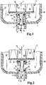
- Fig. 1 shows a schematic cross-sectional view of an oil filter according to the invention of an internal combustion engine, especially for motor vehicles in the region of its lower end in the direction of gravity.
- the oil filter comprises a filter housing 1, of which only the lower region of a removable housing lower part 20 is shown.
- a replaceable filter cartridge 3 is arranged in an interior 2 of the filter housing 1.
- the filter housing 1, including its components described in more detail below, as well as the filter cartridge 3, are constructed coaxially to a longitudinal axis 7 and are substantially rotationally symmetrical.
- the filter housing 1 At its lowermost end in the direction of gravity, the filter housing 1 is provided with a drain valve 4, which lies on the longitudinal axis 7.
- the drain valve 4 comprises a molded in the housing part 20 cylindrical sealing seat 5, in which a coaxial with the longitudinal axis 7 displaceable valve body 6 is held with a circumferential sealing ring 19 at its lower end.
- the valve body 6 is displaceable in the valve seat 5 in a direction of rotation 8 which is coaxial with the longitudinal axis 7 and points towards the interior 2, and in an opposing closing direction 9.
- the filter cartridge 3 comprises an approximately cylindrical filter body 24, which at its lower, the drain valve 4 facing end face with a End plate 23 is provided.
- the end plate 23 is a radial inner side 14 of the filter cartridge 3 fluidly separated from the outside.
- the outside forms a raw side 21 of the filter cartridge 3, while the inner side 14 forms a clean side 22. Due to the fluidic separation of the raw side 21 of the clean side 22 of the arriving at the raw side 21 oil flow is forced to pass radially from the outside through the filter body 24 inside to the clean side 22, wherein the oil flow is filtered.
- a cylindrical receptacle 11 is integrally formed on its axial outer side.
- a further circumferential sealing ring 18 is provided at the end plate 23 at the end plate 23 at the end plate 23 at the end plate 23 at the end plate 23 at the end plate 23 at the end plate 23 at the end plate 23 at the end plate 23 at the end plate 23 at the end plate 23 at the end plate 23 at the end plate 23 at the end plate 23 at the end plate 23 at the end plate 23 is provided with a further circumferential sealing ring 18. The valve body 6 is inserted with this sealing ring 18 in the cylindrical receptacle 11 in the opening direction 8 and held by means of the sealing ring 18 by clamping.
- the receptacle 11 is open to the drain valve 4, so that the valve body 6 in the closing direction 9 by overcoming the clamping force of the sealing ring 18 from the receptacle 11 can be pulled axially.
- a stop for the valve body 6 is formed by the end plate 23 so that it can not be pressed into the inside 14 of the filter cartridge 3.
- the receptacle 11 forms a cylindrical sealing seat 12 of an emptying valve 13 of the filter cartridge 3, through which the inside 14 of the filter cartridge 3 when opening the Emptying valve 13 can be emptied.
- the drain valve 4 of the oil filter or the filter housing 1 and the emptying valve 13 of the filter cartridge 3 therefore engage in their function on the same valve body 6 back.
- the cylindrical valve seat 5 of the drain valve 4 is continuous and open to the outside of the filter housing 1, so that the valve body 6 can be pushed out of its valve seat 5 and out of the filter housing 1 in the closing direction 9 if necessary.
- the valve seat 5 has a retaining device 15 for the valve body 6, which is formed in the embodiment shown by circumferentially distributed spring tongues 16. Accordingly, the valve body 6 can only be moved so far in the opening direction 8 until it rests with the located at its lower end sealing ring 19 or another stop on radially inwardly projecting lugs 16 of the spring tongues.
- a plurality of drain openings 17 are arranged between the individual spring tongues, which pierce the cylindrical valve seat 5 radially. If necessary, the oil located in the interior 2 of the filter housing 1 can be drained through these drain openings 17 as described below.
- Fig. 1 shows the oil filter in the operating state, wherein the upper end of the valve body 6 with its sealing ring 18 is sealingly in the sealing seat 12 of the emptying valve 13.
- the end plate 23 is thus fluidically closed, so that the funded oil flow from the raw side 21 through the filter body 24 passes through to the clean side 22.
- the arranged at the lower end of the valve body 6 sealing ring 19 is located in its valve seat 5 below the drain holes 17, therefore, the drain valve 4 is closed. There can be no oil from the interior 2 to the outside of the filter housing 1.
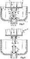
- the Fig. 2 to 5 show in phase pictures the process of replacing the filter cartridge 3.
- the lower housing part 20 is partially released and moved relative to the filter cartridge 3 down.
- the filter cartridge 3, which is not shown on the upper housing part, has its position in relation to the illustration Fig. 1 not changed.
- the clamping force of the valve body 6 with its sealing ring 18 in the receptacle 11 is dimensioned such that the valve body 6 has not changed its relative position to the filter cartridge 3, as a result its lower end with the circumferential sealing ring 19 relative to the operating position Fig. 1 is shifted in its valve seat 5 in the opening direction 8 upwards.
- the sealing ring 19 is above the lower edge of the drain holes 17, therefore, they are open.
- the located in the interior 2 of the filter housing 1 on the raw side 21 oil can - as shown by arrows 25 - run through the drain holes 17 of the drain valve 4.
- the emptying valve 13 of the filter cartridge 3 is further closed, so that there is still oil in the clean-side inside 14 of the filter cartridge 3.
- the maintenance unit 10 comprises a new filter cartridge 3 with a new valve body 6 held in its receptacle 11.
- the new valve body 6 held therein is moved as shown Fig. 5 pushed in the closing direction 9 in the valve seat 5, wherein the corresponding according to the illustration Fig. 4 therein still existing old valve body 6 in the direction of an arrow 28 ( Fig. 5 ), ie in the closing direction 9, is pushed out of the valve seat 5 of the housing lower part 20.
- the spring tongues 16 have in the closing direction 9 acting bevels, according to which the new valve body 6 is pushed with its lower sealing ring 19 in the valve seat 5, as shown in the Fig. 2 and 3 However, can not be pulled out again in the opening direction 8.
- the thus preassembled housing unit from the lower housing part 20 and the maintenance unit 10 can then be fastened again to the upper housing part, not shown.
Description
Die Erfindung betrifft einen Ölfilter eines Verbrennungsmotors insbesondere für Kraftfahrzeuge mit den Merkmalen nach dem Oberbegriff des Anspruchs 1.The invention relates to an oil filter of an internal combustion engine in particular for motor vehicles with the features according to the preamble of
Aus der
Bei der Ölfilterwartung wird das untere Gehäuseteil des Filtergehäuses abgeschraubt und nach unten abgezogen, während die Filterpatrone zunächst in ihrer Betriebsposition am oberen Gehäuseteil verbleibt. Beim Abziehen des unteren Gehäuseteils wird der mit der Filterpatrone verrastete Ventilkörper in einer zum Innenraum des Filtergehäuses hin weisenden Öffnungsrichtung relativ zum Ventilsitz verschoben, wodurch das Ablaufventil geöffnet wird. Das sich im Innenraum des Filtergehäuses befindliche Öl läuft durch das geöffnete Ablaufventil kontrolliert ab. Anschließend kann die Filterpatrone ausgewechselt werden.When oil filter maintenance, the lower housing part of the filter housing is unscrewed and withdrawn down, while the filter cartridge initially remains in its operating position on the upper housing part. When removing the lower housing part of the latched with the filter cartridge valve body is moved relative to the valve seat in a direction of the interior of the filter housing facing opening direction, whereby the drain valve is opened. Located in the interior of the filter housing located oil runs through the open drain valve controlled. Then the filter cartridge can be replaced.
Der Zusammenbau erfolgt in umgekehrter Reihenfolge: Bei axialem Aufschieben des Gehäuseunterteils wird der mit der Filterpatrone verrastete Ventilkörper in der entgegengesetzt zur Öffnungsrichtung liegenden Schließrichtung in den Ventilsitz des Ablaufventils bis an einen axialen Anschlag hineingeschoben.The assembly takes place in the reverse order: With axial sliding of the lower housing part of the latched with the filter cartridge valve body is pushed in the direction opposite to the opening direction closing direction in the valve seat of the drain valve to an axial stop.
Da der Ventilkörper beim Öffnen des Filtergehäuses infolge seiner Clipsverbindung mit der Filterpatrone aus seinem Ventilsitz herausgezogen wird und an der Filterpatrone verbleibt, kann der Benutzer den Ventilkörper von der gebrauchten Filterpatrone abziehen und zusammen mit einer neuen Filterpatrone erneut einsetzen. Dies setzt voraus, dass der Ventilkörper einschließlich seiner Dichtringe mit aufwändigen Maßnahmen für eine hohe Lebensdauer ausgelegt werden muss. Im Übrigen kann nicht sichergestellt werden, dass nach mehrfacher Wiederbenutzung des Ventilkörpers Beschädigungen der Dichtringe ausbleiben und eine dauerhafte Öldichtigkeit erhalten bleibt.Since the valve body is pulled out of its valve seat due to its clip connection with the filter cartridge when opening the filter housing and remains on the filter cartridge, the user can deduct the valve body from the used filter cartridge and re-insert it together with a new filter cartridge. This requires that the valve body including its sealing rings must be designed with elaborate measures for a long service life. Incidentally, it can not be ensured that fail after multiple reuse of the valve body damage the sealing rings and a permanent oil seal is maintained.
Des Weiteren ist die Endscheibe der Filterpatrone im Bereich der Rastverbindung für den Ventilkörper massiv ausgebildet. Hierdurch wird eine öldichte Trennung des Innenraums der Filterpatrone von seiner Außenseite herbeigeführt. Über das Ablaufventil des Filtergehäuses kann zwar das auf der Rohseite der Filterpatrone befindliche Öl abgelassen werden. Auf ihrer Innenseite, also auf ihrer Reinseite befindet sich jedoch weiteres Öl, welches nicht abfließen kann. Bei der Entnahme der gebrauchten Filterpatrone muss erhöhtes Augenmerk darauf gerichtet werden, dass kein Altöl aus der Filterpatrone verschüttet wird.Furthermore, the end disk of the filter cartridge in the region of the latching connection for the valve body is solid. As a result, an oil-tight separation of the interior of the filter cartridge is brought from its outer side. Through the drain valve of the filter housing, although the oil located on the raw side of the filter cartridge can be drained become. On its inside, so on its clean side, however, is more oil, which can not drain. When removing the used filter cartridge, increased attention must be paid to ensure that no used oil is spilled out of the filter cartridge.
Des Weiteren beschreibt die
Der Erfindung liegt die Aufgabe zugrunde, einen gattungsgemäßen Ölfilter derart weiterzubilden, dass die Funktionssicherheit des Ablaufventils verbessert ist.The invention has the object of developing a generic oil filter such that the reliability of the drain valve is improved.
Diese Aufgabe wird durch einen Ölfilter mit den Merkmalen des Anspruchs 1 gelöst.This object is achieved by an oil filter with the features of
Es wird ein Ölfilter vorgeschlagen, bei dem der Ventilkörper des Ablaufventils in der Schließrichtung aus dem Filtergehäuse herausdrückbar ist. Der Ventilkörper bildet zusammen mit der zugehörigen Filterpatrone eine zum gemeinsamen Auswechseln vorgesehene Wartungseinheit. Bevorzugt ist der Ventilkörper axial lösbar und insbesondere klemmend in einer Aufnahme der Filterpatrone gehalten. Hierdurch ist es beim Filterwechsel möglich, dass sich der Ventilkörper bei der Abnahme des Gehäuseunterteils von der Filterpatrone trennt und im Gehäuseunterteil zunächst verbleibt. Der Benutzer ist gezwungen, eine neue Wartungseinheit mit neuer Filterpatrone und neuem Ventilkörper einzusetzen. Beim Einsetzen wird der neue Ventilkörper in der Schließrichtung in den Ventilsitz hineingeschoben, während gleichzeitig der alte, noch darin befindliche Ventilkörper - ebenfalls in der Schließrichtung - aus seinem Ventilsitz herausgedrückt wird. Hierdurch ist ein Missbrauch des alten, gebrauchten Ventilkörpers in Form einer Mehrfachbenutzung vermieden. Das Auswechseln der Wartungseinheit ist einfach und erfordert keine besondere Sachkenntnis. Der stets neue eingesetzte Ventilkörper kann einfach und kostengünstig hergestellt sein, wobei dauerhaft eine Öldichtigkeit sichergestellt ist. Zuverlässigkeit und Funktionssicherheit sind erhöht.An oil filter is proposed in which the valve body of the drain valve can be pushed out of the filter housing in the closing direction. The valve body forms together with the associated filter cartridge intended for common replacement maintenance unit. Preferably, the valve body is axially releasable and in particular held by clamping in a receptacle of the filter cartridge. This makes it possible when changing the filter, that the valve body separates during the removal of the lower housing part of the filter cartridge and in the lower housing part first remains. The user is forced to use a new maintenance unit with a new filter cartridge and a new valve body. When inserting the new valve body is pushed in the closing direction in the valve seat, while at the same time the old, still located therein valve body - also in the closing direction - is pushed out of its valve seat. As a result, a misuse of the old, used valve body in the form of multiple use is avoided. Replacing the maintenance unit is easy and requires no special expertise. The always new valve body used can be made simple and inexpensive, with permanent oil leakage is ensured. Reliability and reliability are increased.
In vorteilhafter Weiterbildung bildet der Ventilkörper zusammen mit einem Dichtsitz der Filterpatrone ein Entleerventil für eine Innenseite der Filterpatrone. Zweckmäßig ist dabei die Aufnahme für den Ventilkörper durch den Dichtsitz der Filterpatrone gebildet, wobei der Ventilkörper mittels eines Dichtringes klemmend und im Übrigen frei herausziehbar in der Aufnahme der Filterpatrone gehalten ist. Dadurch, dass der Ventilkörper beim Öffnen des Filtergehäuses aus der Aufnahme bzw. dem Dichtsitz der Filterpatrone herausgezogen wird, wird auch das Entleerventil der Filterpatrone geöffnet. Das auf der reinseitigen Innenseite der Filterpatrone befindliche Öl kann durch das Entleerventil der Filterpatrone gemeinsam mit dem rohseitigen Öl durch das Ablaufventil aus dem Innenraum des Filtergehäuses ablaufen. Eine nahezu vollständige Entleerung ist möglich. Die gebrauchte Filterpatrone kann ohne die Gefahr des Verschüttens von Öl und dabei ohne besondere Aufmerksamkeit ausgewechselt werden.In an advantageous development, the valve body together with a sealing seat of the filter cartridge forms an emptying valve for an inner side of the filter cartridge. Appropriately, the receptacle for the valve body is formed by the sealing seat of the filter cartridge, wherein the valve body by means of a sealing ring is clamped and otherwise freely pulled out held in the receptacle of the filter cartridge. Characterized in that the valve body is pulled out when opening the filter housing from the receptacle or the sealing seat of the filter cartridge, the drain valve of the filter cartridge is opened. The oil located on the clean-side inside of the filter cartridge can be shared with the emptying valve of the filter cartridge drain off the raw-side oil through the drain valve from the interior of the filter housing. An almost complete emptying is possible. The used filter cartridge can be replaced without the risk of spilling oil and thereby without special attention.
In bevorzugter Weiterbildung weist der Ventilsitz des Ablaufventils eine auf den Ventilkörper in der Öffnungsrichtung einwirkende Rückhalteeinrichtung auf. Zunächst wird der Ventilkörper beim Öffnen des Filtergehäuses in der Öffnungsrichtung relativ zu seinem Ventilsitz bewegt. Diese Bewegung ist jedoch durch die Rückhalteeinrichtung limitiert, so dass der Ventilkörper nicht aus seinem Ventilsitz herausrutschen kann. Vielmehr führt ein weiteres Öffnen bzw. Abziehen des Gehäuseunterteils dazu, dass der an der Rückhalteeinrichtung gehaltene Ventilkörper aus der Aufnahme der Filterpatrone herausgezogen wird und im Filtergehäuse verbleibt. Hierdurch ist eine zuverlässige Trennung des Ventilkörpers von der Filterpatrone bei gleichzeitig zuverlässiger Öffnung des Entleerventils sichergestellt, ohne dass der Benutzer besonderes Augenmerk auf die Lage des Ventilkörpers richten muss.In a preferred embodiment, the valve seat of the drain valve on a force acting on the valve body in the opening direction retaining means. First, the valve body is moved when opening the filter housing in the opening direction relative to its valve seat. However, this movement is limited by the retainer, so that the valve body can not slip out of its valve seat. Rather, a further opening or removal of the lower housing part causes the held on the retaining device valve body is pulled out of the receptacle of the filter cartridge and remains in the filter housing. As a result, a reliable separation of the valve body from the filter cartridge is ensured at the same time reliable opening of the drain valve, without the user must pay particular attention to the position of the valve body.
Die Rückhalteeinrichtung ist bevorzugt durch mindestens eine Federzunge gebildet. Bei konstruktiv einfachem Aufbau ist eine hohe Funktionssicherheit gewährleistet, indem ein neuer Ventilkörper zwar leicht in seinem Ventilsitz eingefädelt, nicht jedoch in Gegenrichtung herausgezogen werden kann.The retaining device is preferably formed by at least one spring tongue. With a structurally simple construction, a high level of functional reliability is ensured by a new valve body, although slightly threaded in its valve seat, but can not be pulled out in the opposite direction.
In einer bevorzugten Ausführungsform weist der Ventilsitz des Ablaufventils eine Ablauföffnung auf, die bei Anlage des Ventilkörpers an der Rückhalteeinrichtung geöffnet ist. Hierdurch kann das Öl ungehindert austreten, ohne dass der Ventilkörper übermäßig weit oder gar vollständig aus seinem insbesondere zylindrischen Dichtsitz herausgezogen werden muss.In a preferred embodiment, the valve seat of the drain valve has a drain opening which is open when the valve body bears against the retaining device. As a result, the oil can escape unhindered without the valve body has to be excessively far or even completely pulled out of its particular cylindrical sealing seat.
Ein Ausführungsbeispiel der Erfindung ist nachfolgend anhand der Zeichnung näher beschrieben. Es zeigen:
-
Figur 1 -
Figur 2Figur 1 -
Figur 3Figuren 1 und 2 -
Figur 4 -
Figuren 1 bis 3 -
Figur 5Figur 4
-
FIG. 1 in a schematic cross-sectional view of an oil filter according to the invention in the region of its drain valve with inserted filter cartridge and valve body in the operating state; -
FIG. 2 the arrangement afterFIG. 1 at partially dissolved lower housing part and opened drain valve; -
FIG. 3 the arrangement after theFigures 1 and 2 at further dissolved housing lower part and additionally opened emptying valve of the filter cartridge; -
FIG. 4 The removed housing lower part of the oil filter after the -
FIGS. 1 to 3 with the valve body stuck in it when fitting a new maintenance unit with a new filter cartridge and a new valve body; -
FIG. 5 the arrangement afterFIG. 4 with inserted new maintenance unit and pushed out old valve body of the drain valve.
An seinem in Schwerkraftrichtung untersten Ende ist das Filtergehäuse 1 mit einem Ablaufventil 4 versehen, welches auf der Längsachse 7 liegt. Das Ablaufventil 4 umfasst einen in das Gehäuseunterteil 20 eingeformten zylindrischen Dichtsitz 5, in dem ein koaxial zur Längsachse 7 verschiebbarer Ventilkörper 6 mit einem umlaufenden Dichtring 19 an seinem unteren Ende gehalten ist. Der Ventilkörper 6 ist in einer koaxial zur Längsachse 7 liegenden, zum Innenraum 2 hin weisenden Öffnungsrichtung 8 sowie in einer entgegengesetzt verlaufenden Schließrichtung 9 im Ventilsitz 5 verschiebbar.At its lowermost end in the direction of gravity, the
Die Filterpatrone 3 umfasst einen etwa zylindrischen Filterkörper 24, der an seiner unteren, dem Ablaufventil 4 zugewandten Stirnseite mit einer Endscheibe 23 versehen ist. Durch die Endscheibe 23 ist eine radiale Innenseite 14 der Filterpatrone 3 strömungstechnisch von der Außenseite getrennt. Die Außenseite bildet eine Rohseite 21 der Filterpatrone 3, während die Innenseite 14 eine Reinseite 22 bildet. Durch die strömungstechnische Trennung der Rohseite 21 von der Reinseite 22 ist der bei der Rohseite 21 ankommende Ölstrom gezwungen, radial von außen durch den Filterkörper 24 hindurch nach innen zur Reinseite 22 hindurchzutreten, wobei der Ölstrom filtriert wird.The
An der Endscheibe 23 ist auf ihrer axialen Außenseite eine zylindrische Aufnahme 11 einteilig angeformt. An seinem der Filterpatrone 3 zugewandten Ende ist der Ventilkörper 6 mit einem weiteren umlaufenden Dichtring 18 versehen. Der Ventilkörper 6 ist mit diesem Dichtring 18 in die zylindrische Aufnahme 11 in der Öffnungsrichtung 8 eingesteckt und dabei mittels des Dichtrings 18 klemmend gehalten.At the
Die Aufnahme 11 ist zum Ablaufventil 4 hin offen, so dass der Ventilkörper 6 in der Schließrichtung 9 unter Überwindung der Klemmkraft des Dichtringes 18 aus der Aufnahme 11 axial herausgezogen werden kann. In der Gegenrichtung ist durch die Endscheibe 23 ein Anschlag für den Ventilkörper 6 gebildet, so dass dieser nicht in die Innenseite 14 der Filterpatrone 3 eingedrückt werden kann. Darüber hinaus bildet die Aufnahme 11 einen zylindrischen Dichtsitz 12 eines Entleerventils 13 der Filterpatrone 3, durch das die Innenseite 14 der Filterpatrone 3 beim Öffnen des Entleerventils 13 entleert werden kann. Das Ablaufventil 4 des Ölfilters bzw. des Filtergehäuses 1 und das Entleerventil 13 der Filterpatrone 3 greifen demnach bei ihrer Funktion auf den gleichen Ventilkörper 6 zurück.The
Der zylindrische Ventilsitz 5 des Ablaufventils 4 ist zur Außenseite des Filtergehäuses 1 hin durchgängig und offen, so dass der Ventilkörper 6 bei Bedarf in der Schließrichtung 9 aus seinem Ventilsitz 5 und aus dem Filtergehäuse 1 herausgedrückt werden kann. In Gegenrichtung, also in der Schließrichtung 8 weist der Ventilsitz 5 eine Rückhalteeinrichtung 15 für den Ventilkörper 6 auf, die im gezeigten Ausführungsbeispiel durch in Umfangsrichtung verteilte Federzungen 16 gebildet ist. Demnach kann der Ventilkörper 6 in der Öffnungsrichtung 8 nur so weit verschoben werden, bis er mit dem an seinem unteren Ende befindlichen Dichtring 19 oder einem anderen Anschlag an radial nach innen hervorstehenden Nasen der Federzungen 16 anliegt. In Umfangsrichtung verteilt sind zwischen den einzelnen Federzungen 16 mehrere Ablauföffnungen 17 angeordnet, die den zylindrischen Ventilsitz 5 radial durchstoßen. Bei Bedarf kann durch diese Ablauföffnungen 17 hindurch das sich im Innenraum 2 des Filtergehäuses 1 befindliche Öl wie nachfolgend beschrieben abgelassen werden.The
Die
Im nächsten Schritt wird - wie in
Nachdem das Filtergehäuseunterteil 20 und die Filterpatrone 3 entleert sind, wird entsprechend der Darstellung nach
Die derart vormontierte Gehäuseeinheit aus dem Gehäuseunterteil 20 und der Wartungseinheit 10 kann anschließend wieder am nicht dargestellten Gehäuseoberteil befestigt werden. Alternativ ist es auch möglich, zunächst die Wartungseinheit 10 in das Gehäuseoberteil einzusetzen und anschließend das Gehäuseunterteil 20 daran zu montieren. Auch in diesem Falle greifen die einzelnen Komponenten in vorstehend beschriebener Weise ineinander.The thus preassembled housing unit from the
Claims (7)
- Oil filter of an internal combustion engine in particular for motor vehicles, comprising a filter housing (1), an exchangeable filter cartridge (3) disposed in an interior space (2) of the filter housing (1), as well as a drain valve (4) in the filter housing (1), wherein the drain valve (4) features a valve seat (5) for a valve body (6) in which the valve body (6) is displaceable in an opening direction (8) parallel and in particular coaxially to a longitudinal axis (7) of the oil filter and pointing towards the interior space (2) and wherein the valve body (6) is inserted into the valve seat (5) of the drain valve (4) in a closing direction (9) opposite to the opening direction (8) and wherein the valve body (6) forms together with the filter cartridge (3) a maintenance unit (10) provided for a common replacement, characterized in that the valve body (6) can be pressed out of the filter housing (1) in the closing direction (9).
- Oil filter according to claim 1, characterized in that the valve body (6) is held detachably and in particular in a clamped position in a support (11) of the filter cartridge (3).
- Oil filter according to claim 1 or 2, characterized in that the valve body (6) forms together with a sealing seat (12) of the filter cartridge (3) a drain valve (13) for an interior side (14) of the filter cartridge (3).
- Oil filter according to one of the claims 1 to 3, characterized in that the valve seat (5) of the drain valve (4) features a retaining means (15) acting on the valve body (6) in the opening direction (8).
- Oil filter according to claim 4, characterized in that the retaining means (15) is formed by at least one spring tab (16).
- Oil filter according to claim 4 or 5, characterized in that the valve seat (5) of the drain valve (4) features a drain opening (17) which is opened when the valve body (6) contacts the retaining means (15).
- Oil filter according to claim 2, characterized in that the support (11) for the valve body (6) is formed by the sealing seat (12) of the filter cartridge (3) and that the valve body (6) is held by means of a sealing ring (18) in a clamped position and moreover freely removably in the support (11) of the filter cartridge (3).
Applications Claiming Priority (1)
| Application Number | Priority Date | Filing Date | Title |
|---|---|---|---|
| DE202007017964U DE202007017964U1 (en) | 2007-12-20 | 2007-12-20 | Oil filter of an internal combustion engine and filter cartridge for the oil filter |
Publications (2)
| Publication Number | Publication Date |
|---|---|
| EP2072768A1 EP2072768A1 (en) | 2009-06-24 |
| EP2072768B1 true EP2072768B1 (en) | 2017-03-01 |
Family
ID=40221300
Family Applications (1)
| Application Number | Title | Priority Date | Filing Date |
|---|---|---|---|
| EP08167609.0A Not-in-force EP2072768B1 (en) | 2007-12-20 | 2008-10-27 | Oil filter of a combustion engine and filter cartridge for the oil filter |
Country Status (4)
| Country | Link |
|---|---|
| US (1) | US8920649B2 (en) |
| EP (1) | EP2072768B1 (en) |
| CN (1) | CN101463741B (en) |
| DE (1) | DE202007017964U1 (en) |
Cited By (1)
| Publication number | Priority date | Publication date | Assignee | Title |
|---|---|---|---|---|
| DE102017004275A1 (en) * | 2017-05-04 | 2018-11-08 | Mann+Hummel Gmbh | Filter element for liquid filtration |
Families Citing this family (9)
| Publication number | Priority date | Publication date | Assignee | Title |
|---|---|---|---|---|
| DE112011105233T5 (en) * | 2011-05-11 | 2014-03-27 | Cummins Filtration Ip Inc. | "No filter, no operation" Feature for a filter |
| DE102011120646B4 (en) * | 2011-12-09 | 2018-11-08 | Mann+Hummel Gmbh | Liquid filter and filter element with drain valve of a liquid filter |
| CN103939176B (en) * | 2014-04-23 | 2016-03-30 | 安徽江淮汽车股份有限公司 | A kind of motor and engine oil filtering apparatus thereof |
| WO2016146152A1 (en) | 2015-03-13 | 2016-09-22 | Volvo Truck Corporation | An engine arrangement |
| US20170100686A1 (en) * | 2015-10-13 | 2017-04-13 | Caterpillar Inc. | Liquid Filter |
| US10201772B2 (en) * | 2016-01-22 | 2019-02-12 | Caterpillar Inc. | Filter element and filter system |
| PL3618939T3 (en) * | 2017-04-30 | 2023-08-07 | Mann+Hummel Gmbh | An oil housing, filter element, and valving assembly for providing pre-charged oil volume changes |
| US11946396B2 (en) | 2020-09-09 | 2024-04-02 | Lubrication Technologies, Inc. | Liquid filter arrangement for no-mess liquid change |
| CN116679624B (en) * | 2022-12-20 | 2023-11-10 | 江苏高福新能源有限公司 | Supply scheduling device with multi-energy structure and control system |
Family Cites Families (12)
| Publication number | Priority date | Publication date | Assignee | Title |
|---|---|---|---|---|
| US2693281A (en) * | 1950-03-17 | 1954-11-02 | Bendix Aviat Corp | Filter |
| DE19635777A1 (en) * | 1996-09-04 | 1998-03-05 | Mann & Hummel Filter | Assembly for an internal combustion engine |
| JP3692655B2 (en) * | 1996-10-07 | 2005-09-07 | 株式会社デンソー | Element exchange type filter |
| DE29921543U1 (en) * | 1999-12-07 | 2001-04-12 | Hengst Walter Gmbh & Co Kg | Filter insert for a liquid filter |
| DE19961580A1 (en) * | 1999-12-21 | 2001-06-28 | Mann & Hummel Filter | Liquid filter with drain for liquid residues |
| DE10038531A1 (en) * | 2000-08-08 | 2002-02-21 | Mann & Hummel Filter | liquid filters |
| JP3793749B2 (en) * | 2002-11-15 | 2006-07-05 | トヨタ紡織株式会社 | Element exchange type filter and its drain mechanism |
| DE102004031209A1 (en) * | 2004-06-28 | 2006-01-19 | Mann + Hummel Gmbh | liquid filters |
| DE102004058885B4 (en) | 2004-12-06 | 2016-12-22 | Mann + Hummel Gmbh | Füssigkeitsfilter |
| FR2885819B1 (en) * | 2005-05-20 | 2008-02-29 | Filtrauto Sa | CONTROLLED DRAINING DEVICE OF A LIQUID FILTER |
| DE202007006385U1 (en) * | 2006-05-10 | 2007-09-20 | Hengst Gmbh & Co.Kg | Liquid filter with return valve in the clean-side flow channel |
| DE112008001571B4 (en) * | 2007-06-18 | 2018-11-29 | Cummins Filtration Ip, Inc. | Fluid filter and method for servicing a fluid filter |
-
2007
- 2007-12-20 DE DE202007017964U patent/DE202007017964U1/en not_active Expired - Lifetime
-
2008
- 2008-10-27 EP EP08167609.0A patent/EP2072768B1/en not_active Not-in-force
- 2008-12-16 US US12/335,785 patent/US8920649B2/en not_active Expired - Fee Related
- 2008-12-22 CN CN2008101889629A patent/CN101463741B/en not_active Expired - Fee Related
Non-Patent Citations (1)
| Title |
|---|
| None * |
Cited By (2)
| Publication number | Priority date | Publication date | Assignee | Title |
|---|---|---|---|---|
| DE102017004275A1 (en) * | 2017-05-04 | 2018-11-08 | Mann+Hummel Gmbh | Filter element for liquid filtration |
| US11305217B2 (en) | 2017-05-04 | 2022-04-19 | Mann+Hummel Gmbh | Filter element for liquid filtration |
Also Published As
| Publication number | Publication date |
|---|---|
| US8920649B2 (en) | 2014-12-30 |
| CN101463741A (en) | 2009-06-24 |
| DE202007017964U1 (en) | 2009-04-30 |
| CN101463741B (en) | 2013-05-22 |
| US20090159520A1 (en) | 2009-06-25 |
| EP2072768A1 (en) | 2009-06-24 |
Similar Documents
| Publication | Publication Date | Title |
|---|---|---|
| EP2072768B1 (en) | Oil filter of a combustion engine and filter cartridge for the oil filter | |
| EP1974786B1 (en) | Liquid filter | |
| EP3004620B1 (en) | Filter element | |
| DE102004058885B4 (en) | Füssigkeitsfilter | |
| EP2102484B1 (en) | Fuel filter of a vehicle internal combustion engine | |
| EP1307274B1 (en) | Liquid filter, especially for lubricating oil of a combustion engine | |
| EP1937962B1 (en) | Internal combustion engine in particular on a motor vehicle with a fuel filter device | |
| EP2229232B1 (en) | Fluid filter | |
| EP2015790A2 (en) | Liquid filter with a non-return valve in the filtered side flow channel | |
| DE112013005747B4 (en) | Filter, filter element, filter housing and discharge device of a filter | |
| DE19961580A1 (en) | Liquid filter with drain for liquid residues | |
| WO2013178680A1 (en) | Filter device | |
| WO2008009324A1 (en) | Oil filter assembly and filter element therefor | |
| EP2072103B1 (en) | Filter cartridge and oil filter of a combustion motor | |
| WO2017088962A1 (en) | Filter cartridge for an oil filter of a motor vehicle, and oil filter | |
| EP2062633A1 (en) | Filter assembly with a filtering element | |
| WO2016058691A1 (en) | Filter element for a filter device of an internal combustion engine and filter device for an internal combustion engine | |
| EP2337618A1 (en) | Filter device | |
| EP2808071B1 (en) | Filter device, in particular for an automotive car | |
| EP3458175B1 (en) | Filter device | |
| EP1560636B1 (en) | Liquid filter, especially an oil filter for motor vehicles | |
| DE102019108957A1 (en) | Filter with a filter housing, with an exchangeable filter element and with a seal carrier on it | |
| DE102014019145A1 (en) | Filter device for a motor vehicle and filter element for filtering a liquid | |
| EP3099394A1 (en) | Filter device with drainage means in the cover | |
| EP3727641B1 (en) | Filter system with non-return valve and filter element |
Legal Events
| Date | Code | Title | Description |
|---|---|---|---|
| PUAI | Public reference made under article 153(3) epc to a published international application that has entered the european phase |
Free format text: ORIGINAL CODE: 0009012 |
|
| AK | Designated contracting states |
Kind code of ref document: A1 Designated state(s): AT BE BG CH CY CZ DE DK EE ES FI FR GB GR HR HU IE IS IT LI LT LU LV MC MT NL NO PL PT RO SE SI SK TR |
|
| AX | Request for extension of the european patent |
Extension state: AL BA MK RS |
|
| 17P | Request for examination filed |
Effective date: 20090811 |
|
| 17Q | First examination report despatched |
Effective date: 20090907 |
|
| AKX | Designation fees paid |
Designated state(s): AT BE BG CH CY CZ DE DK EE ES FI FR GB GR HR HU IE IS IT LI LT LU LV MC MT NL NO PL PT RO SE SI SK TR |
|
| GRAP | Despatch of communication of intention to grant a patent |
Free format text: ORIGINAL CODE: EPIDOSNIGR1 |
|
| INTG | Intention to grant announced |
Effective date: 20160920 |
|
| GRAS | Grant fee paid |
Free format text: ORIGINAL CODE: EPIDOSNIGR3 |
|
| GRAA | (expected) grant |
Free format text: ORIGINAL CODE: 0009210 |
|
| AK | Designated contracting states |
Kind code of ref document: B1 Designated state(s): AT BE BG CH CY CZ DE DK EE ES FI FR GB GR HR HU IE IS IT LI LT LU LV MC MT NL NO PL PT RO SE SI SK TR |
|
| REG | Reference to a national code |
Ref country code: GB Ref legal event code: FG4D Free format text: NOT ENGLISH |
|
| REG | Reference to a national code |
Ref country code: CH Ref legal event code: EP Ref country code: AT Ref legal event code: REF Ref document number: 871630 Country of ref document: AT Kind code of ref document: T Effective date: 20170315 |
|
| REG | Reference to a national code |
Ref country code: IE Ref legal event code: FG4D Free format text: LANGUAGE OF EP DOCUMENT: GERMAN |
|
| REG | Reference to a national code |
Ref country code: DE Ref legal event code: R096 Ref document number: 502008015063 Country of ref document: DE |
|
| REG | Reference to a national code |
Ref country code: NL Ref legal event code: MP Effective date: 20170301 |
|
| REG | Reference to a national code |
Ref country code: LT Ref legal event code: MG4D |
|
| PG25 | Lapsed in a contracting state [announced via postgrant information from national office to epo] |
Ref country code: FI Free format text: LAPSE BECAUSE OF FAILURE TO SUBMIT A TRANSLATION OF THE DESCRIPTION OR TO PAY THE FEE WITHIN THE PRESCRIBED TIME-LIMIT Effective date: 20170301 Ref country code: LT Free format text: LAPSE BECAUSE OF FAILURE TO SUBMIT A TRANSLATION OF THE DESCRIPTION OR TO PAY THE FEE WITHIN THE PRESCRIBED TIME-LIMIT Effective date: 20170301 Ref country code: NO Free format text: LAPSE BECAUSE OF FAILURE TO SUBMIT A TRANSLATION OF THE DESCRIPTION OR TO PAY THE FEE WITHIN THE PRESCRIBED TIME-LIMIT Effective date: 20170601 Ref country code: GR Free format text: LAPSE BECAUSE OF FAILURE TO SUBMIT A TRANSLATION OF THE DESCRIPTION OR TO PAY THE FEE WITHIN THE PRESCRIBED TIME-LIMIT Effective date: 20170602 Ref country code: HR Free format text: LAPSE BECAUSE OF FAILURE TO SUBMIT A TRANSLATION OF THE DESCRIPTION OR TO PAY THE FEE WITHIN THE PRESCRIBED TIME-LIMIT Effective date: 20170301 |
|
| PG25 | Lapsed in a contracting state [announced via postgrant information from national office to epo] |
Ref country code: LV Free format text: LAPSE BECAUSE OF FAILURE TO SUBMIT A TRANSLATION OF THE DESCRIPTION OR TO PAY THE FEE WITHIN THE PRESCRIBED TIME-LIMIT Effective date: 20170301 Ref country code: SE Free format text: LAPSE BECAUSE OF FAILURE TO SUBMIT A TRANSLATION OF THE DESCRIPTION OR TO PAY THE FEE WITHIN THE PRESCRIBED TIME-LIMIT Effective date: 20170301 Ref country code: BG Free format text: LAPSE BECAUSE OF FAILURE TO SUBMIT A TRANSLATION OF THE DESCRIPTION OR TO PAY THE FEE WITHIN THE PRESCRIBED TIME-LIMIT Effective date: 20170601 Ref country code: ES Free format text: LAPSE BECAUSE OF FAILURE TO SUBMIT A TRANSLATION OF THE DESCRIPTION OR TO PAY THE FEE WITHIN THE PRESCRIBED TIME-LIMIT Effective date: 20170301 |
|
| PG25 | Lapsed in a contracting state [announced via postgrant information from national office to epo] |
Ref country code: NL Free format text: LAPSE BECAUSE OF FAILURE TO SUBMIT A TRANSLATION OF THE DESCRIPTION OR TO PAY THE FEE WITHIN THE PRESCRIBED TIME-LIMIT Effective date: 20170301 |
|
| PG25 | Lapsed in a contracting state [announced via postgrant information from national office to epo] |
Ref country code: RO Free format text: LAPSE BECAUSE OF FAILURE TO SUBMIT A TRANSLATION OF THE DESCRIPTION OR TO PAY THE FEE WITHIN THE PRESCRIBED TIME-LIMIT Effective date: 20170301 Ref country code: IT Free format text: LAPSE BECAUSE OF FAILURE TO SUBMIT A TRANSLATION OF THE DESCRIPTION OR TO PAY THE FEE WITHIN THE PRESCRIBED TIME-LIMIT Effective date: 20170301 Ref country code: CZ Free format text: LAPSE BECAUSE OF FAILURE TO SUBMIT A TRANSLATION OF THE DESCRIPTION OR TO PAY THE FEE WITHIN THE PRESCRIBED TIME-LIMIT Effective date: 20170301 Ref country code: EE Free format text: LAPSE BECAUSE OF FAILURE TO SUBMIT A TRANSLATION OF THE DESCRIPTION OR TO PAY THE FEE WITHIN THE PRESCRIBED TIME-LIMIT Effective date: 20170301 Ref country code: SK Free format text: LAPSE BECAUSE OF FAILURE TO SUBMIT A TRANSLATION OF THE DESCRIPTION OR TO PAY THE FEE WITHIN THE PRESCRIBED TIME-LIMIT Effective date: 20170301 |
|
| PG25 | Lapsed in a contracting state [announced via postgrant information from national office to epo] |
Ref country code: PT Free format text: LAPSE BECAUSE OF FAILURE TO SUBMIT A TRANSLATION OF THE DESCRIPTION OR TO PAY THE FEE WITHIN THE PRESCRIBED TIME-LIMIT Effective date: 20170703 Ref country code: IS Free format text: LAPSE BECAUSE OF FAILURE TO SUBMIT A TRANSLATION OF THE DESCRIPTION OR TO PAY THE FEE WITHIN THE PRESCRIBED TIME-LIMIT Effective date: 20170701 Ref country code: PL Free format text: LAPSE BECAUSE OF FAILURE TO SUBMIT A TRANSLATION OF THE DESCRIPTION OR TO PAY THE FEE WITHIN THE PRESCRIBED TIME-LIMIT Effective date: 20170301 |
|
| REG | Reference to a national code |
Ref country code: DE Ref legal event code: R097 Ref document number: 502008015063 Country of ref document: DE |
|
| PLBE | No opposition filed within time limit |
Free format text: ORIGINAL CODE: 0009261 |
|
| STAA | Information on the status of an ep patent application or granted ep patent |
Free format text: STATUS: NO OPPOSITION FILED WITHIN TIME LIMIT |
|
| PG25 | Lapsed in a contracting state [announced via postgrant information from national office to epo] |
Ref country code: DK Free format text: LAPSE BECAUSE OF FAILURE TO SUBMIT A TRANSLATION OF THE DESCRIPTION OR TO PAY THE FEE WITHIN THE PRESCRIBED TIME-LIMIT Effective date: 20170301 |
|
| PGFP | Annual fee paid to national office [announced via postgrant information from national office to epo] |
Ref country code: DE Payment date: 20171019 Year of fee payment: 10 |
|
| 26N | No opposition filed |
Effective date: 20171204 |
|
| PG25 | Lapsed in a contracting state [announced via postgrant information from national office to epo] |
Ref country code: SI Free format text: LAPSE BECAUSE OF FAILURE TO SUBMIT A TRANSLATION OF THE DESCRIPTION OR TO PAY THE FEE WITHIN THE PRESCRIBED TIME-LIMIT Effective date: 20170301 |
|
| PG25 | Lapsed in a contracting state [announced via postgrant information from national office to epo] |
Ref country code: MC Free format text: LAPSE BECAUSE OF FAILURE TO SUBMIT A TRANSLATION OF THE DESCRIPTION OR TO PAY THE FEE WITHIN THE PRESCRIBED TIME-LIMIT Effective date: 20170301 |
|
| REG | Reference to a national code |
Ref country code: CH Ref legal event code: PL |
|
| GBPC | Gb: european patent ceased through non-payment of renewal fee |
Effective date: 20171027 |
|
| REG | Reference to a national code |
Ref country code: DE Ref legal event code: R081 Ref document number: 502008015063 Country of ref document: DE Owner name: MANN+HUMMEL GMBH, DE Free format text: FORMER OWNER: MANN + HUMMEL GMBH, 71638 LUDWIGSBURG, DE |
|
| REG | Reference to a national code |
Ref country code: IE Ref legal event code: MM4A |
|
| REG | Reference to a national code |
Ref country code: FR Ref legal event code: ST Effective date: 20180629 |
|
| PG25 | Lapsed in a contracting state [announced via postgrant information from national office to epo] |
Ref country code: LU Free format text: LAPSE BECAUSE OF NON-PAYMENT OF DUE FEES Effective date: 20171027 Ref country code: CH Free format text: LAPSE BECAUSE OF NON-PAYMENT OF DUE FEES Effective date: 20171031 Ref country code: GB Free format text: LAPSE BECAUSE OF NON-PAYMENT OF DUE FEES Effective date: 20171027 Ref country code: LI Free format text: LAPSE BECAUSE OF NON-PAYMENT OF DUE FEES Effective date: 20171031 |
|
| REG | Reference to a national code |
Ref country code: BE Ref legal event code: MM Effective date: 20171031 |
|
| PG25 | Lapsed in a contracting state [announced via postgrant information from national office to epo] |
Ref country code: FR Free format text: LAPSE BECAUSE OF NON-PAYMENT OF DUE FEES Effective date: 20171031 Ref country code: BE Free format text: LAPSE BECAUSE OF NON-PAYMENT OF DUE FEES Effective date: 20171031 |
|
| PG25 | Lapsed in a contracting state [announced via postgrant information from national office to epo] |
Ref country code: MT Free format text: LAPSE BECAUSE OF FAILURE TO SUBMIT A TRANSLATION OF THE DESCRIPTION OR TO PAY THE FEE WITHIN THE PRESCRIBED TIME-LIMIT Effective date: 20170301 |
|
| PG25 | Lapsed in a contracting state [announced via postgrant information from national office to epo] |
Ref country code: IE Free format text: LAPSE BECAUSE OF NON-PAYMENT OF DUE FEES Effective date: 20171027 |
|
| REG | Reference to a national code |
Ref country code: AT Ref legal event code: MM01 Ref document number: 871630 Country of ref document: AT Kind code of ref document: T Effective date: 20171027 |
|
| PG25 | Lapsed in a contracting state [announced via postgrant information from national office to epo] |
Ref country code: AT Free format text: LAPSE BECAUSE OF NON-PAYMENT OF DUE FEES Effective date: 20171027 |
|
| REG | Reference to a national code |
Ref country code: DE Ref legal event code: R119 Ref document number: 502008015063 Country of ref document: DE |
|
| PG25 | Lapsed in a contracting state [announced via postgrant information from national office to epo] |
Ref country code: HU Free format text: LAPSE BECAUSE OF FAILURE TO SUBMIT A TRANSLATION OF THE DESCRIPTION OR TO PAY THE FEE WITHIN THE PRESCRIBED TIME-LIMIT; INVALID AB INITIO Effective date: 20081027 |
|
| PG25 | Lapsed in a contracting state [announced via postgrant information from national office to epo] |
Ref country code: DE Free format text: LAPSE BECAUSE OF NON-PAYMENT OF DUE FEES Effective date: 20190501 |
|
| PG25 | Lapsed in a contracting state [announced via postgrant information from national office to epo] |
Ref country code: CY Free format text: LAPSE BECAUSE OF NON-PAYMENT OF DUE FEES Effective date: 20170301 |
|
| PG25 | Lapsed in a contracting state [announced via postgrant information from national office to epo] |
Ref country code: TR Free format text: LAPSE BECAUSE OF FAILURE TO SUBMIT A TRANSLATION OF THE DESCRIPTION OR TO PAY THE FEE WITHIN THE PRESCRIBED TIME-LIMIT Effective date: 20170301 |