EP2072768B1 - Filtre à huile d'un moteur à combustion interne et cartouche de filtre pour le filtre à huile - Google Patents
Filtre à huile d'un moteur à combustion interne et cartouche de filtre pour le filtre à huile Download PDFInfo
- Publication number
- EP2072768B1 EP2072768B1 EP08167609.0A EP08167609A EP2072768B1 EP 2072768 B1 EP2072768 B1 EP 2072768B1 EP 08167609 A EP08167609 A EP 08167609A EP 2072768 B1 EP2072768 B1 EP 2072768B1
- Authority
- EP
- European Patent Office
- Prior art keywords
- valve body
- valve
- filter
- filter cartridge
- oil
- Prior art date
- Legal status (The legal status is an assumption and is not a legal conclusion. Google has not performed a legal analysis and makes no representation as to the accuracy of the status listed.)
- Not-in-force
Links
- 238000002485 combustion reaction Methods 0.000 title claims description 5
- 238000007789 sealing Methods 0.000 claims description 28
- 238000012423 maintenance Methods 0.000 claims description 12
- 210000002105 tongue Anatomy 0.000 description 6
- 230000005484 gravity Effects 0.000 description 3
- 238000000926 separation method Methods 0.000 description 3
- 238000010276 construction Methods 0.000 description 1
- 239000012530 fluid Substances 0.000 description 1
- 239000007788 liquid Substances 0.000 description 1
- 238000000034 method Methods 0.000 description 1
- 239000007787 solid Substances 0.000 description 1
- 239000010913 used oil Substances 0.000 description 1
Images

Classifications
-
- F—MECHANICAL ENGINEERING; LIGHTING; HEATING; WEAPONS; BLASTING
- F01—MACHINES OR ENGINES IN GENERAL; ENGINE PLANTS IN GENERAL; STEAM ENGINES
- F01M—LUBRICATING OF MACHINES OR ENGINES IN GENERAL; LUBRICATING INTERNAL COMBUSTION ENGINES; CRANKCASE VENTILATING
- F01M11/00—Component parts, details or accessories, not provided for in, or of interest apart from, groups F01M1/00 - F01M9/00
- F01M11/03—Mounting or connecting of lubricant purifying means relative to the machine or engine; Details of lubricant purifying means
-
- B—PERFORMING OPERATIONS; TRANSPORTING
- B01—PHYSICAL OR CHEMICAL PROCESSES OR APPARATUS IN GENERAL
- B01D—SEPARATION
- B01D29/00—Filters with filtering elements stationary during filtration, e.g. pressure or suction filters, not covered by groups B01D24/00 - B01D27/00; Filtering elements therefor
- B01D29/96—Filters with filtering elements stationary during filtration, e.g. pressure or suction filters, not covered by groups B01D24/00 - B01D27/00; Filtering elements therefor in which the filtering elements are moved between filtering operations; Particular measures for removing or replacing the filtering elements; Transport systems for filters
-
- B—PERFORMING OPERATIONS; TRANSPORTING
- B01—PHYSICAL OR CHEMICAL PROCESSES OR APPARATUS IN GENERAL
- B01D—SEPARATION
- B01D35/00—Filtering devices having features not specifically covered by groups B01D24/00 - B01D33/00, or for applications not specifically covered by groups B01D24/00 - B01D33/00; Auxiliary devices for filtration; Filter housing constructions
- B01D35/14—Safety devices specially adapted for filtration; Devices for indicating clogging
- B01D35/153—Anti-leakage or anti-return valves
-
- B—PERFORMING OPERATIONS; TRANSPORTING
- B01—PHYSICAL OR CHEMICAL PROCESSES OR APPARATUS IN GENERAL
- B01D—SEPARATION
- B01D35/00—Filtering devices having features not specifically covered by groups B01D24/00 - B01D33/00, or for applications not specifically covered by groups B01D24/00 - B01D33/00; Auxiliary devices for filtration; Filter housing constructions
- B01D35/16—Cleaning-out devices, e.g. for removing the cake from the filter casing or for evacuating the last remnants of liquid
-
- F—MECHANICAL ENGINEERING; LIGHTING; HEATING; WEAPONS; BLASTING
- F01—MACHINES OR ENGINES IN GENERAL; ENGINE PLANTS IN GENERAL; STEAM ENGINES
- F01M—LUBRICATING OF MACHINES OR ENGINES IN GENERAL; LUBRICATING INTERNAL COMBUSTION ENGINES; CRANKCASE VENTILATING
- F01M1/00—Pressure lubrication
- F01M1/10—Lubricating systems characterised by the provision therein of lubricant venting or purifying means, e.g. of filters
- F01M2001/105—Lubricating systems characterised by the provision therein of lubricant venting or purifying means, e.g. of filters characterised by the layout of the purification arrangements
- F01M2001/1064—Lubricating systems characterised by the provision therein of lubricant venting or purifying means, e.g. of filters characterised by the layout of the purification arrangements comprising drains for oil to the carter, e.g. to recover spilled oil during change of filters
Definitions
- the invention relates to an oil filter of an internal combustion engine in particular for motor vehicles with the features according to the preamble of claim 1.
- an oil filter of an internal combustion engine wherein an interchangeable filter cartridge is arranged in the interior of its filter housing. Furthermore, the filter housing is provided at its lower end in the direction of gravity with a drain valve, by means of which the filter housing can be emptied when changing the filter cartridge.
- a drain valve In a valve seat of the drain valve a coaxial with the longitudinal axis of the oil filter slidable valve body is arranged, which is locked with an end plate of the filter cartridge.
- the lower housing part of the filter housing When oil filter maintenance, the lower housing part of the filter housing is unscrewed and withdrawn down, while the filter cartridge initially remains in its operating position on the upper housing part.
- the drain valve When removing the lower housing part of the latched with the filter cartridge valve body is moved relative to the valve seat in a direction of the interior of the filter housing facing opening direction, whereby the drain valve is opened. Located in the interior of the filter housing located oil runs through the open drain valve controlled. Then the filter cartridge can be replaced.
- the assembly takes place in the reverse order: With axial sliding of the lower housing part of the latched with the filter cartridge valve body is pushed in the direction opposite to the opening direction closing direction in the valve seat of the drain valve to an axial stop.
- valve body Since the valve body is pulled out of its valve seat due to its clip connection with the filter cartridge when opening the filter housing and remains on the filter cartridge, the user can deduct the valve body from the used filter cartridge and re-insert it together with a new filter cartridge.
- the end disk of the filter cartridge in the region of the latching connection for the valve body is solid.
- an oil-tight separation of the interior of the filter cartridge is brought from its outer side.
- the drain valve of the filter housing Although the oil located on the raw side of the filter cartridge can be drained become. On its inside, so on its clean side, however, is more oil, which can not drain.
- increased attention must be paid to ensure that no used oil is spilled out of the filter cartridge.
- the drain valve has a valve body connected to a replaceable filter cartridge via a valve rod and a support body.
- the invention has the object of developing a generic oil filter such that the reliability of the drain valve is improved.
- valve body of the drain valve can be pushed out of the filter housing in the closing direction.
- the valve body forms together with the associated filter cartridge intended for common replacement maintenance unit.
- the valve body is axially releasable and in particular held by clamping in a receptacle of the filter cartridge. This makes it possible when changing the filter, that the valve body separates during the removal of the lower housing part of the filter cartridge and in the lower housing part first remains. The user is forced to use a new maintenance unit with a new filter cartridge and a new valve body.
- the valve body together with a sealing seat of the filter cartridge forms an emptying valve for an inner side of the filter cartridge.
- the receptacle for the valve body is formed by the sealing seat of the filter cartridge, wherein the valve body by means of a sealing ring is clamped and otherwise freely pulled out held in the receptacle of the filter cartridge.
- the valve body is pulled out when opening the filter housing from the receptacle or the sealing seat of the filter cartridge, the drain valve of the filter cartridge is opened.
- the oil located on the clean-side inside of the filter cartridge can be shared with the emptying valve of the filter cartridge drain off the raw-side oil through the drain valve from the interior of the filter housing. An almost complete emptying is possible.
- the used filter cartridge can be replaced without the risk of spilling oil and thereby without special attention.
- valve seat of the drain valve on a force acting on the valve body in the opening direction retaining means First, the valve body is moved when opening the filter housing in the opening direction relative to its valve seat. However, this movement is limited by the retainer, so that the valve body can not slip out of its valve seat. Rather, a further opening or removal of the lower housing part causes the held on the retaining device valve body is pulled out of the receptacle of the filter cartridge and remains in the filter housing. As a result, a reliable separation of the valve body from the filter cartridge is ensured at the same time reliable opening of the drain valve, without the user must pay particular attention to the position of the valve body.
- the retaining device is preferably formed by at least one spring tongue.
- valve seat of the drain valve has a drain opening which is open when the valve body bears against the retaining device.
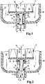
- Fig. 1 shows a schematic cross-sectional view of an oil filter according to the invention of an internal combustion engine, especially for motor vehicles in the region of its lower end in the direction of gravity.
- the oil filter comprises a filter housing 1, of which only the lower region of a removable housing lower part 20 is shown.
- a replaceable filter cartridge 3 is arranged in an interior 2 of the filter housing 1.
- the filter housing 1, including its components described in more detail below, as well as the filter cartridge 3, are constructed coaxially to a longitudinal axis 7 and are substantially rotationally symmetrical.
- the filter housing 1 At its lowermost end in the direction of gravity, the filter housing 1 is provided with a drain valve 4, which lies on the longitudinal axis 7.
- the drain valve 4 comprises a molded in the housing part 20 cylindrical sealing seat 5, in which a coaxial with the longitudinal axis 7 displaceable valve body 6 is held with a circumferential sealing ring 19 at its lower end.
- the valve body 6 is displaceable in the valve seat 5 in a direction of rotation 8 which is coaxial with the longitudinal axis 7 and points towards the interior 2, and in an opposing closing direction 9.
- the filter cartridge 3 comprises an approximately cylindrical filter body 24, which at its lower, the drain valve 4 facing end face with a End plate 23 is provided.
- the end plate 23 is a radial inner side 14 of the filter cartridge 3 fluidly separated from the outside.
- the outside forms a raw side 21 of the filter cartridge 3, while the inner side 14 forms a clean side 22. Due to the fluidic separation of the raw side 21 of the clean side 22 of the arriving at the raw side 21 oil flow is forced to pass radially from the outside through the filter body 24 inside to the clean side 22, wherein the oil flow is filtered.
- a cylindrical receptacle 11 is integrally formed on its axial outer side.
- a further circumferential sealing ring 18 is provided at the end plate 23 at the end plate 23 at the end plate 23 at the end plate 23 at the end plate 23 at the end plate 23 at the end plate 23 at the end plate 23 at the end plate 23 at the end plate 23 at the end plate 23 at the end plate 23 at the end plate 23 at the end plate 23 at the end plate 23 at the end plate 23 is provided with a further circumferential sealing ring 18. The valve body 6 is inserted with this sealing ring 18 in the cylindrical receptacle 11 in the opening direction 8 and held by means of the sealing ring 18 by clamping.
- the receptacle 11 is open to the drain valve 4, so that the valve body 6 in the closing direction 9 by overcoming the clamping force of the sealing ring 18 from the receptacle 11 can be pulled axially.
- a stop for the valve body 6 is formed by the end plate 23 so that it can not be pressed into the inside 14 of the filter cartridge 3.
- the receptacle 11 forms a cylindrical sealing seat 12 of an emptying valve 13 of the filter cartridge 3, through which the inside 14 of the filter cartridge 3 when opening the Emptying valve 13 can be emptied.
- the drain valve 4 of the oil filter or the filter housing 1 and the emptying valve 13 of the filter cartridge 3 therefore engage in their function on the same valve body 6 back.
- the cylindrical valve seat 5 of the drain valve 4 is continuous and open to the outside of the filter housing 1, so that the valve body 6 can be pushed out of its valve seat 5 and out of the filter housing 1 in the closing direction 9 if necessary.
- the valve seat 5 has a retaining device 15 for the valve body 6, which is formed in the embodiment shown by circumferentially distributed spring tongues 16. Accordingly, the valve body 6 can only be moved so far in the opening direction 8 until it rests with the located at its lower end sealing ring 19 or another stop on radially inwardly projecting lugs 16 of the spring tongues.
- a plurality of drain openings 17 are arranged between the individual spring tongues, which pierce the cylindrical valve seat 5 radially. If necessary, the oil located in the interior 2 of the filter housing 1 can be drained through these drain openings 17 as described below.
- Fig. 1 shows the oil filter in the operating state, wherein the upper end of the valve body 6 with its sealing ring 18 is sealingly in the sealing seat 12 of the emptying valve 13.
- the end plate 23 is thus fluidically closed, so that the funded oil flow from the raw side 21 through the filter body 24 passes through to the clean side 22.
- the arranged at the lower end of the valve body 6 sealing ring 19 is located in its valve seat 5 below the drain holes 17, therefore, the drain valve 4 is closed. There can be no oil from the interior 2 to the outside of the filter housing 1.
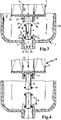
- the Fig. 2 to 5 show in phase pictures the process of replacing the filter cartridge 3.
- the lower housing part 20 is partially released and moved relative to the filter cartridge 3 down.
- the filter cartridge 3, which is not shown on the upper housing part, has its position in relation to the illustration Fig. 1 not changed.
- the clamping force of the valve body 6 with its sealing ring 18 in the receptacle 11 is dimensioned such that the valve body 6 has not changed its relative position to the filter cartridge 3, as a result its lower end with the circumferential sealing ring 19 relative to the operating position Fig. 1 is shifted in its valve seat 5 in the opening direction 8 upwards.
- the sealing ring 19 is above the lower edge of the drain holes 17, therefore, they are open.
- the located in the interior 2 of the filter housing 1 on the raw side 21 oil can - as shown by arrows 25 - run through the drain holes 17 of the drain valve 4.
- the emptying valve 13 of the filter cartridge 3 is further closed, so that there is still oil in the clean-side inside 14 of the filter cartridge 3.
- the maintenance unit 10 comprises a new filter cartridge 3 with a new valve body 6 held in its receptacle 11.
- the new valve body 6 held therein is moved as shown Fig. 5 pushed in the closing direction 9 in the valve seat 5, wherein the corresponding according to the illustration Fig. 4 therein still existing old valve body 6 in the direction of an arrow 28 ( Fig. 5 ), ie in the closing direction 9, is pushed out of the valve seat 5 of the housing lower part 20.
- the spring tongues 16 have in the closing direction 9 acting bevels, according to which the new valve body 6 is pushed with its lower sealing ring 19 in the valve seat 5, as shown in the Fig. 2 and 3 However, can not be pulled out again in the opening direction 8.
- the thus preassembled housing unit from the lower housing part 20 and the maintenance unit 10 can then be fastened again to the upper housing part, not shown.
Claims (7)
- Filtre à huile d'un moteur de combustion interne en particulier pour des véhicules automobiles, comprenant un boîtier de filtre (1), une cartouche filtrante (3) échangeable disposée dans un espace intérieur (2) du boîtier de filtre (1), ainsi qu'une vanne d'écoulement (4) dans le boîtier de filtre (1), la vanne d'écoulement (4) présentant un siège de soupape (5) pour un corps de soupape (6) dans lequel le corps de soupape (6) peut être déplacé dans une direction d'ouverture (8) située de manière parallèle et en particulier coaxiale par rapport à un axe longitudinal (7) du filtre à huile et orientée vers l'espace intérieur (2), et le corps de soupape (6) étant inséré dans le siège de soupape (5) de la vanne d'écoulement (4) dans une direction de fermeture (9) opposée à la direction d'ouverture (8), et le corps de soupape (6) formant avec la cartouche filtrante (3) une unité d'entretien (10) destinée à l'échange commun, caractérisé en ce que le corps de soupape (6) peut être pressé hors du boîtier de filtre (1) dans la direction de fermeture (9).
- Filtre à huile selon la revendication 1, caractérisé en ce que le corps de soupape (6) est maintenu de manière amovible et en particulier par serrage dans un logement (11) de la cartouche filtrante (3).
- Filtre à huile selon la revendication 1 ou 2, caractérisé en ce que le corps de soupape (6) forme, avec un siège d'étanchéité (12) de la cartouche filtrante (3), une vanne de purge (13) pour une face intérieure (14) de la cartouche filtrante (3).
- Filtre à huile selon l'une des revendications 1 à 3, caractérisé en ce que le siège de soupape (5) de la vanne d'écoulement (4) est pourvu d'un dispositif de retenue (15) agissant sur le corps de soupape (6) dans la direction d'ouverture (8).
- Filtre à huile selon la revendication 4, caractérisé en ce que le dispositif de retenue (15) est formé par au moins une languette élastique (16).
- Filtre à huile selon la revendication 4 ou 5, caractérisé en ce que le siège de soupape (5) de la vanne d'écoulement (4) présente une ouverture d'évacuation (17) qui est ouverte lorsque le corps de soupape (6) touche le dispositif de retenue (15).
- Filtre à huile selon la revendication 2, caractérisé en ce que le logement (11) pour le corps de soupape (6) est formé par le siège d'étanchéité (12) de la cartouche filtrante (3) et que le corps de soupape (6) est maintenu par serrage, au moyen d'une bague d'étanchéité (18), dans le logement (11) de la cartouche filtrante (3) et, du reste, peut en être extrait librement.
Applications Claiming Priority (1)
| Application Number | Priority Date | Filing Date | Title |
|---|---|---|---|
| DE202007017964U DE202007017964U1 (de) | 2007-12-20 | 2007-12-20 | Ölfilter eines Verbrennungsmotors und Filterpatrone für den Ölfilter |
Publications (2)
| Publication Number | Publication Date |
|---|---|
| EP2072768A1 EP2072768A1 (fr) | 2009-06-24 |
| EP2072768B1 true EP2072768B1 (fr) | 2017-03-01 |
Family
ID=40221300
Family Applications (1)
| Application Number | Title | Priority Date | Filing Date |
|---|---|---|---|
| EP08167609.0A Not-in-force EP2072768B1 (fr) | 2007-12-20 | 2008-10-27 | Filtre à huile d'un moteur à combustion interne et cartouche de filtre pour le filtre à huile |
Country Status (4)
| Country | Link |
|---|---|
| US (1) | US8920649B2 (fr) |
| EP (1) | EP2072768B1 (fr) |
| CN (1) | CN101463741B (fr) |
| DE (1) | DE202007017964U1 (fr) |
Cited By (1)
| Publication number | Priority date | Publication date | Assignee | Title |
|---|---|---|---|---|
| DE102017004275A1 (de) * | 2017-05-04 | 2018-11-08 | Mann+Hummel Gmbh | Filterelement zur Flüssigkeitsfiltration |
Families Citing this family (9)
| Publication number | Priority date | Publication date | Assignee | Title |
|---|---|---|---|---|
| WO2012151749A1 (fr) * | 2011-05-11 | 2012-11-15 | Cummins Filtration Ip Inc. | Élément sans filtre et sans déplacement pour filtre |
| DE102011120646B4 (de) * | 2011-12-09 | 2018-11-08 | Mann+Hummel Gmbh | Flüssigkeitsfilter und Filterelement mit Ablaufschwert eines Flüssigkeitsfilters |
| CN103939176B (zh) * | 2014-04-23 | 2016-03-30 | 安徽江淮汽车股份有限公司 | 一种发动机及其机油滤清装置 |
| EP3268594B1 (fr) | 2015-03-13 | 2019-11-13 | Volvo Truck Corporation | Ensemble turbine |
| US20170100686A1 (en) * | 2015-10-13 | 2017-04-13 | Caterpillar Inc. | Liquid Filter |
| US10201772B2 (en) * | 2016-01-22 | 2019-02-12 | Caterpillar Inc. | Filter element and filter system |
| WO2018202599A1 (fr) * | 2017-04-30 | 2018-11-08 | Mann+Hummel Gmbh | Boîtier d'huile, élément filtrant et ensemble soupape pour fournir des changements de volume d'huile préchargé |
| US11946396B2 (en) | 2020-09-09 | 2024-04-02 | Lubrication Technologies, Inc. | Liquid filter arrangement for no-mess liquid change |
| CN116679624B (zh) * | 2022-12-20 | 2023-11-10 | 江苏高福新能源有限公司 | 一种具有多能源结构的供给调度装置及控制系统 |
Family Cites Families (12)
| Publication number | Priority date | Publication date | Assignee | Title |
|---|---|---|---|---|
| US2693281A (en) * | 1950-03-17 | 1954-11-02 | Bendix Aviat Corp | Filter |
| DE19635777A1 (de) * | 1996-09-04 | 1998-03-05 | Mann & Hummel Filter | Baugruppe für eine Verbrennungskraftmaschine |
| JP3692655B2 (ja) * | 1996-10-07 | 2005-09-07 | 株式会社デンソー | エレメント交換型フィルタ |
| DE29921543U1 (de) * | 1999-12-07 | 2001-04-12 | Hengst Walter Gmbh & Co Kg | Filtereinsatz für einen Flüssigkeitsfilter |
| DE19961580A1 (de) | 1999-12-21 | 2001-06-28 | Mann & Hummel Filter | Flüssigkeitsfilter mit Ablaß für Flüssigkeitsrückstände |
| DE10038531A1 (de) * | 2000-08-08 | 2002-02-21 | Mann & Hummel Filter | Flüssigkeitsfilter |
| JP3793749B2 (ja) * | 2002-11-15 | 2006-07-05 | トヨタ紡織株式会社 | エレメント交換型フィルタ及びそのドレン機構 |
| DE102004031209A1 (de) * | 2004-06-28 | 2006-01-19 | Mann + Hummel Gmbh | Flüssigkeitsfilter |
| DE102004058885B4 (de) * | 2004-12-06 | 2016-12-22 | Mann + Hummel Gmbh | Füssigkeitsfilter |
| FR2885819B1 (fr) * | 2005-05-20 | 2008-02-29 | Filtrauto Sa | Dispositif de vidange controlee d'un filtre a liquide |
| DE202007006385U1 (de) * | 2006-05-10 | 2007-09-20 | Hengst Gmbh & Co.Kg | Flüssigkeitsfilter mit Rücklaufsperrventil im reinseitigen Strömungskanal |
| WO2008157597A2 (fr) * | 2007-06-18 | 2008-12-24 | Cummins Filtration Ip, Inc. | Valve de purge pour service et procédé de filtre |
-
2007
- 2007-12-20 DE DE202007017964U patent/DE202007017964U1/de not_active Expired - Lifetime
-
2008
- 2008-10-27 EP EP08167609.0A patent/EP2072768B1/fr not_active Not-in-force
- 2008-12-16 US US12/335,785 patent/US8920649B2/en not_active Expired - Fee Related
- 2008-12-22 CN CN2008101889629A patent/CN101463741B/zh not_active Expired - Fee Related
Non-Patent Citations (1)
| Title |
|---|
| None * |
Cited By (2)
| Publication number | Priority date | Publication date | Assignee | Title |
|---|---|---|---|---|
| DE102017004275A1 (de) * | 2017-05-04 | 2018-11-08 | Mann+Hummel Gmbh | Filterelement zur Flüssigkeitsfiltration |
| US11305217B2 (en) | 2017-05-04 | 2022-04-19 | Mann+Hummel Gmbh | Filter element for liquid filtration |
Also Published As
| Publication number | Publication date |
|---|---|
| US20090159520A1 (en) | 2009-06-25 |
| DE202007017964U1 (de) | 2009-04-30 |
| CN101463741B (zh) | 2013-05-22 |
| CN101463741A (zh) | 2009-06-24 |
| US8920649B2 (en) | 2014-12-30 |
| EP2072768A1 (fr) | 2009-06-24 |
Similar Documents
| Publication | Publication Date | Title |
|---|---|---|
| EP2072768B1 (fr) | Filtre à huile d'un moteur à combustion interne et cartouche de filtre pour le filtre à huile | |
| EP1974786B1 (fr) | Filtre liquide | |
| EP3004620B1 (fr) | Élément filtrant | |
| DE102004058885B4 (de) | Füssigkeitsfilter | |
| EP2102484B1 (fr) | Filtre à carburant d'un moteur à combustion de véhicule | |
| EP1307274B1 (fr) | Filtre pour liquide, en particulier pour huile de lubrification d'un moteur a combustion | |
| EP1937962B1 (fr) | Moteur a combustion, notamment d'un vehicule, comportant un systeme de filtre a carburant | |
| EP2229232B1 (fr) | Filtre à liquides | |
| WO2007128306A2 (fr) | Filtre à liquide comprenant un clapet anti-retour situé dans le canal d'écoulement côté filtré | |
| DE112013005747B4 (de) | Filter, Filterelement, Filtergehäuse und Ablassvorrichtung eines Filters | |
| DE19961580A1 (de) | Flüssigkeitsfilter mit Ablaß für Flüssigkeitsrückstände | |
| EP2854986A1 (fr) | Système de filtre | |
| WO2008009324A1 (fr) | Ensemble filtre à huile et élément filtrant associé | |
| EP2072103B1 (fr) | Cartouche de filtre et filtre à huile d'un moteur à combustion | |
| WO2017088962A1 (fr) | Cartouche filtrante pour un filtre à huile d'un véhicule automobile et filtre à huile | |
| EP2062633A1 (fr) | Dispositif de filtration avec un élément filtrant | |
| WO2016058691A1 (fr) | Élément filtrant pour dispositif de filtration d'un moteur a combustion interne et dispositif de filtration pour moteur a combustion interne | |
| WO2010040594A1 (fr) | Dispositif filtrant | |
| EP2808071B1 (fr) | Dispositif de filtre, en particulier pour un véhicule automobile | |
| EP3458175B1 (fr) | Dispositif de filtration | |
| EP1560636B1 (fr) | Filtre pour liquide, notamment filtre a huile pour vehicules automobiles | |
| DE102019108957A1 (de) | Filter mit einem Filtergehäuse, mit einem auswechselbaren Filtereinsatz und mit einem Dichtungsträger daran | |
| DE102014019145A1 (de) | Filtervorrichtung für einen Kraftwagen und Filtereinsatz zum Filtern einer Flüssigkeit | |
| WO2015113846A1 (fr) | Moyen de filtration à déversoir dans le couvercle | |
| EP3727641B1 (fr) | Système de filtration comportant un clapet anti-retour et un élément filtrant |
Legal Events
| Date | Code | Title | Description |
|---|---|---|---|
| PUAI | Public reference made under article 153(3) epc to a published international application that has entered the european phase |
Free format text: ORIGINAL CODE: 0009012 |
|
| AK | Designated contracting states |
Kind code of ref document: A1 Designated state(s): AT BE BG CH CY CZ DE DK EE ES FI FR GB GR HR HU IE IS IT LI LT LU LV MC MT NL NO PL PT RO SE SI SK TR |
|
| AX | Request for extension of the european patent |
Extension state: AL BA MK RS |
|
| 17P | Request for examination filed |
Effective date: 20090811 |
|
| 17Q | First examination report despatched |
Effective date: 20090907 |
|
| AKX | Designation fees paid |
Designated state(s): AT BE BG CH CY CZ DE DK EE ES FI FR GB GR HR HU IE IS IT LI LT LU LV MC MT NL NO PL PT RO SE SI SK TR |
|
| GRAP | Despatch of communication of intention to grant a patent |
Free format text: ORIGINAL CODE: EPIDOSNIGR1 |
|
| INTG | Intention to grant announced |
Effective date: 20160920 |
|
| GRAS | Grant fee paid |
Free format text: ORIGINAL CODE: EPIDOSNIGR3 |
|
| GRAA | (expected) grant |
Free format text: ORIGINAL CODE: 0009210 |
|
| AK | Designated contracting states |
Kind code of ref document: B1 Designated state(s): AT BE BG CH CY CZ DE DK EE ES FI FR GB GR HR HU IE IS IT LI LT LU LV MC MT NL NO PL PT RO SE SI SK TR |
|
| REG | Reference to a national code |
Ref country code: GB Ref legal event code: FG4D Free format text: NOT ENGLISH |
|
| REG | Reference to a national code |
Ref country code: CH Ref legal event code: EP Ref country code: AT Ref legal event code: REF Ref document number: 871630 Country of ref document: AT Kind code of ref document: T Effective date: 20170315 |
|
| REG | Reference to a national code |
Ref country code: IE Ref legal event code: FG4D Free format text: LANGUAGE OF EP DOCUMENT: GERMAN |
|
| REG | Reference to a national code |
Ref country code: DE Ref legal event code: R096 Ref document number: 502008015063 Country of ref document: DE |
|
| REG | Reference to a national code |
Ref country code: NL Ref legal event code: MP Effective date: 20170301 |
|
| REG | Reference to a national code |
Ref country code: LT Ref legal event code: MG4D |
|
| PG25 | Lapsed in a contracting state [announced via postgrant information from national office to epo] |
Ref country code: FI Free format text: LAPSE BECAUSE OF FAILURE TO SUBMIT A TRANSLATION OF THE DESCRIPTION OR TO PAY THE FEE WITHIN THE PRESCRIBED TIME-LIMIT Effective date: 20170301 Ref country code: LT Free format text: LAPSE BECAUSE OF FAILURE TO SUBMIT A TRANSLATION OF THE DESCRIPTION OR TO PAY THE FEE WITHIN THE PRESCRIBED TIME-LIMIT Effective date: 20170301 Ref country code: NO Free format text: LAPSE BECAUSE OF FAILURE TO SUBMIT A TRANSLATION OF THE DESCRIPTION OR TO PAY THE FEE WITHIN THE PRESCRIBED TIME-LIMIT Effective date: 20170601 Ref country code: GR Free format text: LAPSE BECAUSE OF FAILURE TO SUBMIT A TRANSLATION OF THE DESCRIPTION OR TO PAY THE FEE WITHIN THE PRESCRIBED TIME-LIMIT Effective date: 20170602 Ref country code: HR Free format text: LAPSE BECAUSE OF FAILURE TO SUBMIT A TRANSLATION OF THE DESCRIPTION OR TO PAY THE FEE WITHIN THE PRESCRIBED TIME-LIMIT Effective date: 20170301 |
|
| PG25 | Lapsed in a contracting state [announced via postgrant information from national office to epo] |
Ref country code: LV Free format text: LAPSE BECAUSE OF FAILURE TO SUBMIT A TRANSLATION OF THE DESCRIPTION OR TO PAY THE FEE WITHIN THE PRESCRIBED TIME-LIMIT Effective date: 20170301 Ref country code: SE Free format text: LAPSE BECAUSE OF FAILURE TO SUBMIT A TRANSLATION OF THE DESCRIPTION OR TO PAY THE FEE WITHIN THE PRESCRIBED TIME-LIMIT Effective date: 20170301 Ref country code: BG Free format text: LAPSE BECAUSE OF FAILURE TO SUBMIT A TRANSLATION OF THE DESCRIPTION OR TO PAY THE FEE WITHIN THE PRESCRIBED TIME-LIMIT Effective date: 20170601 Ref country code: ES Free format text: LAPSE BECAUSE OF FAILURE TO SUBMIT A TRANSLATION OF THE DESCRIPTION OR TO PAY THE FEE WITHIN THE PRESCRIBED TIME-LIMIT Effective date: 20170301 |
|
| PG25 | Lapsed in a contracting state [announced via postgrant information from national office to epo] |
Ref country code: NL Free format text: LAPSE BECAUSE OF FAILURE TO SUBMIT A TRANSLATION OF THE DESCRIPTION OR TO PAY THE FEE WITHIN THE PRESCRIBED TIME-LIMIT Effective date: 20170301 |
|
| PG25 | Lapsed in a contracting state [announced via postgrant information from national office to epo] |
Ref country code: RO Free format text: LAPSE BECAUSE OF FAILURE TO SUBMIT A TRANSLATION OF THE DESCRIPTION OR TO PAY THE FEE WITHIN THE PRESCRIBED TIME-LIMIT Effective date: 20170301 Ref country code: IT Free format text: LAPSE BECAUSE OF FAILURE TO SUBMIT A TRANSLATION OF THE DESCRIPTION OR TO PAY THE FEE WITHIN THE PRESCRIBED TIME-LIMIT Effective date: 20170301 Ref country code: CZ Free format text: LAPSE BECAUSE OF FAILURE TO SUBMIT A TRANSLATION OF THE DESCRIPTION OR TO PAY THE FEE WITHIN THE PRESCRIBED TIME-LIMIT Effective date: 20170301 Ref country code: EE Free format text: LAPSE BECAUSE OF FAILURE TO SUBMIT A TRANSLATION OF THE DESCRIPTION OR TO PAY THE FEE WITHIN THE PRESCRIBED TIME-LIMIT Effective date: 20170301 Ref country code: SK Free format text: LAPSE BECAUSE OF FAILURE TO SUBMIT A TRANSLATION OF THE DESCRIPTION OR TO PAY THE FEE WITHIN THE PRESCRIBED TIME-LIMIT Effective date: 20170301 |
|
| PG25 | Lapsed in a contracting state [announced via postgrant information from national office to epo] |
Ref country code: PT Free format text: LAPSE BECAUSE OF FAILURE TO SUBMIT A TRANSLATION OF THE DESCRIPTION OR TO PAY THE FEE WITHIN THE PRESCRIBED TIME-LIMIT Effective date: 20170703 Ref country code: IS Free format text: LAPSE BECAUSE OF FAILURE TO SUBMIT A TRANSLATION OF THE DESCRIPTION OR TO PAY THE FEE WITHIN THE PRESCRIBED TIME-LIMIT Effective date: 20170701 Ref country code: PL Free format text: LAPSE BECAUSE OF FAILURE TO SUBMIT A TRANSLATION OF THE DESCRIPTION OR TO PAY THE FEE WITHIN THE PRESCRIBED TIME-LIMIT Effective date: 20170301 |
|
| REG | Reference to a national code |
Ref country code: DE Ref legal event code: R097 Ref document number: 502008015063 Country of ref document: DE |
|
| PLBE | No opposition filed within time limit |
Free format text: ORIGINAL CODE: 0009261 |
|
| STAA | Information on the status of an ep patent application or granted ep patent |
Free format text: STATUS: NO OPPOSITION FILED WITHIN TIME LIMIT |
|
| PG25 | Lapsed in a contracting state [announced via postgrant information from national office to epo] |
Ref country code: DK Free format text: LAPSE BECAUSE OF FAILURE TO SUBMIT A TRANSLATION OF THE DESCRIPTION OR TO PAY THE FEE WITHIN THE PRESCRIBED TIME-LIMIT Effective date: 20170301 |
|
| PGFP | Annual fee paid to national office [announced via postgrant information from national office to epo] |
Ref country code: DE Payment date: 20171019 Year of fee payment: 10 |
|
| 26N | No opposition filed |
Effective date: 20171204 |
|
| PG25 | Lapsed in a contracting state [announced via postgrant information from national office to epo] |
Ref country code: SI Free format text: LAPSE BECAUSE OF FAILURE TO SUBMIT A TRANSLATION OF THE DESCRIPTION OR TO PAY THE FEE WITHIN THE PRESCRIBED TIME-LIMIT Effective date: 20170301 |
|
| PG25 | Lapsed in a contracting state [announced via postgrant information from national office to epo] |
Ref country code: MC Free format text: LAPSE BECAUSE OF FAILURE TO SUBMIT A TRANSLATION OF THE DESCRIPTION OR TO PAY THE FEE WITHIN THE PRESCRIBED TIME-LIMIT Effective date: 20170301 |
|
| REG | Reference to a national code |
Ref country code: CH Ref legal event code: PL |
|
| GBPC | Gb: european patent ceased through non-payment of renewal fee |
Effective date: 20171027 |
|
| REG | Reference to a national code |
Ref country code: DE Ref legal event code: R081 Ref document number: 502008015063 Country of ref document: DE Owner name: MANN+HUMMEL GMBH, DE Free format text: FORMER OWNER: MANN + HUMMEL GMBH, 71638 LUDWIGSBURG, DE |
|
| REG | Reference to a national code |
Ref country code: IE Ref legal event code: MM4A |
|
| REG | Reference to a national code |
Ref country code: FR Ref legal event code: ST Effective date: 20180629 |
|
| PG25 | Lapsed in a contracting state [announced via postgrant information from national office to epo] |
Ref country code: LU Free format text: LAPSE BECAUSE OF NON-PAYMENT OF DUE FEES Effective date: 20171027 Ref country code: CH Free format text: LAPSE BECAUSE OF NON-PAYMENT OF DUE FEES Effective date: 20171031 Ref country code: GB Free format text: LAPSE BECAUSE OF NON-PAYMENT OF DUE FEES Effective date: 20171027 Ref country code: LI Free format text: LAPSE BECAUSE OF NON-PAYMENT OF DUE FEES Effective date: 20171031 |
|
| REG | Reference to a national code |
Ref country code: BE Ref legal event code: MM Effective date: 20171031 |
|
| PG25 | Lapsed in a contracting state [announced via postgrant information from national office to epo] |
Ref country code: FR Free format text: LAPSE BECAUSE OF NON-PAYMENT OF DUE FEES Effective date: 20171031 Ref country code: BE Free format text: LAPSE BECAUSE OF NON-PAYMENT OF DUE FEES Effective date: 20171031 |
|
| PG25 | Lapsed in a contracting state [announced via postgrant information from national office to epo] |
Ref country code: MT Free format text: LAPSE BECAUSE OF FAILURE TO SUBMIT A TRANSLATION OF THE DESCRIPTION OR TO PAY THE FEE WITHIN THE PRESCRIBED TIME-LIMIT Effective date: 20170301 |
|
| PG25 | Lapsed in a contracting state [announced via postgrant information from national office to epo] |
Ref country code: IE Free format text: LAPSE BECAUSE OF NON-PAYMENT OF DUE FEES Effective date: 20171027 |
|
| REG | Reference to a national code |
Ref country code: AT Ref legal event code: MM01 Ref document number: 871630 Country of ref document: AT Kind code of ref document: T Effective date: 20171027 |
|
| PG25 | Lapsed in a contracting state [announced via postgrant information from national office to epo] |
Ref country code: AT Free format text: LAPSE BECAUSE OF NON-PAYMENT OF DUE FEES Effective date: 20171027 |
|
| REG | Reference to a national code |
Ref country code: DE Ref legal event code: R119 Ref document number: 502008015063 Country of ref document: DE |
|
| PG25 | Lapsed in a contracting state [announced via postgrant information from national office to epo] |
Ref country code: HU Free format text: LAPSE BECAUSE OF FAILURE TO SUBMIT A TRANSLATION OF THE DESCRIPTION OR TO PAY THE FEE WITHIN THE PRESCRIBED TIME-LIMIT; INVALID AB INITIO Effective date: 20081027 |
|
| PG25 | Lapsed in a contracting state [announced via postgrant information from national office to epo] |
Ref country code: DE Free format text: LAPSE BECAUSE OF NON-PAYMENT OF DUE FEES Effective date: 20190501 |
|
| PG25 | Lapsed in a contracting state [announced via postgrant information from national office to epo] |
Ref country code: CY Free format text: LAPSE BECAUSE OF NON-PAYMENT OF DUE FEES Effective date: 20170301 |
|
| PG25 | Lapsed in a contracting state [announced via postgrant information from national office to epo] |
Ref country code: TR Free format text: LAPSE BECAUSE OF FAILURE TO SUBMIT A TRANSLATION OF THE DESCRIPTION OR TO PAY THE FEE WITHIN THE PRESCRIBED TIME-LIMIT Effective date: 20170301 |