EP3668411B1 - Dispositif ultrasonore intraluminal à fréquence réglable - Google Patents
Dispositif ultrasonore intraluminal à fréquence réglable Download PDFInfo
- Publication number
- EP3668411B1 EP3668411B1 EP18762018.2A EP18762018A EP3668411B1 EP 3668411 B1 EP3668411 B1 EP 3668411B1 EP 18762018 A EP18762018 A EP 18762018A EP 3668411 B1 EP3668411 B1 EP 3668411B1
- Authority
- EP
- European Patent Office
- Prior art keywords
- ultrasound
- electrical signal
- transducer array
- intraluminal
- transducer
- Prior art date
- Legal status (The legal status is an assumption and is not a legal conclusion. Google has not performed a legal analysis and makes no representation as to the accuracy of the status listed.)
- Active
Links
- 238000002604 ultrasonography Methods 0.000 title claims description 290
- 238000012285 ultrasound imaging Methods 0.000 claims description 40
- 238000002560 therapeutic procedure Methods 0.000 claims description 39
- 238000012545 processing Methods 0.000 claims description 35
- 230000004044 response Effects 0.000 claims description 27
- 239000002831 pharmacologic agent Substances 0.000 claims description 16
- 239000012528 membrane Substances 0.000 claims description 9
- 238000004891 communication Methods 0.000 claims description 7
- 210000003484 anatomy Anatomy 0.000 description 47
- 238000003384 imaging method Methods 0.000 description 24
- 238000000034 method Methods 0.000 description 24
- 230000002308 calcification Effects 0.000 description 14
- 239000004020 conductor Substances 0.000 description 10
- 238000002592 echocardiography Methods 0.000 description 10
- 230000001225 therapeutic effect Effects 0.000 description 10
- 239000000463 material Substances 0.000 description 9
- 239000000758 substrate Substances 0.000 description 9
- 210000004204 blood vessel Anatomy 0.000 description 8
- 238000002608 intravascular ultrasound Methods 0.000 description 8
- 229940079593 drug Drugs 0.000 description 6
- 239000003814 drug Substances 0.000 description 6
- 239000012530 fluid Substances 0.000 description 6
- 230000002792 vascular Effects 0.000 description 6
- 230000008859 change Effects 0.000 description 5
- 210000005166 vasculature Anatomy 0.000 description 5
- 208000007536 Thrombosis Diseases 0.000 description 4
- 238000005520 cutting process Methods 0.000 description 4
- 238000012377 drug delivery Methods 0.000 description 4
- 229920000642 polymer Polymers 0.000 description 4
- 238000009210 therapy by ultrasound Methods 0.000 description 4
- 208000013201 Stress fracture Diseases 0.000 description 3
- 238000002679 ablation Methods 0.000 description 3
- 229910052451 lead zirconate titanate Inorganic materials 0.000 description 3
- 230000007246 mechanism Effects 0.000 description 3
- 239000004033 plastic Substances 0.000 description 3
- 229920003023 plastic Polymers 0.000 description 3
- OYPRJOBELJOOCE-UHFFFAOYSA-N Calcium Chemical compound [Ca] OYPRJOBELJOOCE-UHFFFAOYSA-N 0.000 description 2
- 239000004677 Nylon Substances 0.000 description 2
- 229920002614 Polyether block amide Polymers 0.000 description 2
- XUIMIQQOPSSXEZ-UHFFFAOYSA-N Silicon Chemical compound [Si] XUIMIQQOPSSXEZ-UHFFFAOYSA-N 0.000 description 2
- 210000001367 artery Anatomy 0.000 description 2
- 230000000712 assembly Effects 0.000 description 2
- 238000000429 assembly Methods 0.000 description 2
- 230000008901 benefit Effects 0.000 description 2
- 230000005540 biological transmission Effects 0.000 description 2
- 210000004369 blood Anatomy 0.000 description 2
- 239000008280 blood Substances 0.000 description 2
- 229910052791 calcium Inorganic materials 0.000 description 2
- 239000011575 calcium Substances 0.000 description 2
- 238000012512 characterization method Methods 0.000 description 2
- 239000002131 composite material Substances 0.000 description 2
- 238000001514 detection method Methods 0.000 description 2
- 238000003745 diagnosis Methods 0.000 description 2
- 238000010586 diagram Methods 0.000 description 2
- 239000003527 fibrinolytic agent Substances 0.000 description 2
- 230000006870 function Effects 0.000 description 2
- 230000036541 health Effects 0.000 description 2
- 210000002216 heart Anatomy 0.000 description 2
- 238000002955 isolation Methods 0.000 description 2
- 238000004519 manufacturing process Methods 0.000 description 2
- 230000004048 modification Effects 0.000 description 2
- 238000012986 modification Methods 0.000 description 2
- 229920001778 nylon Polymers 0.000 description 2
- 230000008569 process Effects 0.000 description 2
- 229910052710 silicon Inorganic materials 0.000 description 2
- 239000010703 silicon Substances 0.000 description 2
- 238000013175 transesophageal echocardiography Methods 0.000 description 2
- 208000031481 Pathologic Constriction Diseases 0.000 description 1
- 244000208734 Pisonia aculeata Species 0.000 description 1
- 239000004642 Polyimide Substances 0.000 description 1
- FAPWRFPIFSIZLT-UHFFFAOYSA-M Sodium chloride Chemical compound [Na+].[Cl-] FAPWRFPIFSIZLT-UHFFFAOYSA-M 0.000 description 1
- 108010023197 Streptokinase Proteins 0.000 description 1
- 239000004809 Teflon Substances 0.000 description 1
- 229920006362 Teflon® Polymers 0.000 description 1
- 108090000373 Tissue Plasminogen Activator Proteins 0.000 description 1
- 102000003978 Tissue Plasminogen Activator Human genes 0.000 description 1
- 108090000435 Urokinase-type plasminogen activator Proteins 0.000 description 1
- 102000003990 Urokinase-type plasminogen activator Human genes 0.000 description 1
- 230000004913 activation Effects 0.000 description 1
- 239000000853 adhesive Substances 0.000 description 1
- 230000001070 adhesive effect Effects 0.000 description 1
- 230000004931 aggregating effect Effects 0.000 description 1
- 239000000956 alloy Substances 0.000 description 1
- 229910045601 alloy Inorganic materials 0.000 description 1
- 230000004075 alteration Effects 0.000 description 1
- 230000003321 amplification Effects 0.000 description 1
- 238000004458 analytical method Methods 0.000 description 1
- 239000004019 antithrombin Substances 0.000 description 1
- 238000003491 array Methods 0.000 description 1
- 230000017531 blood circulation Effects 0.000 description 1
- 210000004556 brain Anatomy 0.000 description 1
- 230000000747 cardiac effect Effects 0.000 description 1
- 230000015556 catabolic process Effects 0.000 description 1
- 239000003795 chemical substances by application Substances 0.000 description 1
- 239000013078 crystal Substances 0.000 description 1
- 230000003247 decreasing effect Effects 0.000 description 1
- 238000006731 degradation reaction Methods 0.000 description 1
- 230000002939 deleterious effect Effects 0.000 description 1
- 238000000151 deposition Methods 0.000 description 1
- 230000008021 deposition Effects 0.000 description 1
- 238000002405 diagnostic procedure Methods 0.000 description 1
- 238000010790 dilution Methods 0.000 description 1
- 239000012895 dilution Substances 0.000 description 1
- 238000005516 engineering process Methods 0.000 description 1
- 210000003743 erythrocyte Anatomy 0.000 description 1
- 210000003238 esophagus Anatomy 0.000 description 1
- 238000011049 filling Methods 0.000 description 1
- 238000001914 filtration Methods 0.000 description 1
- 238000010304 firing Methods 0.000 description 1
- 210000000232 gallbladder Anatomy 0.000 description 1
- 239000011521 glass Substances 0.000 description 1
- 238000000227 grinding Methods 0.000 description 1
- 210000003709 heart valve Anatomy 0.000 description 1
- 238000010438 heat treatment Methods 0.000 description 1
- 238000003780 insertion Methods 0.000 description 1
- 230000037431 insertion Effects 0.000 description 1
- 210000000936 intestine Anatomy 0.000 description 1
- 230000001788 irregular Effects 0.000 description 1
- 210000003734 kidney Anatomy 0.000 description 1
- HFGPZNIAWCZYJU-UHFFFAOYSA-N lead zirconate titanate Chemical compound [O-2].[O-2].[O-2].[O-2].[O-2].[Ti+4].[Zr+4].[Pb+2] HFGPZNIAWCZYJU-UHFFFAOYSA-N 0.000 description 1
- 230000003902 lesion Effects 0.000 description 1
- 210000004185 liver Anatomy 0.000 description 1
- 210000004072 lung Anatomy 0.000 description 1
- 239000000203 mixture Substances 0.000 description 1
- 238000000465 moulding Methods 0.000 description 1
- 230000001338 necrotic effect Effects 0.000 description 1
- 210000000653 nervous system Anatomy 0.000 description 1
- 230000001537 neural effect Effects 0.000 description 1
- 238000003199 nucleic acid amplification method Methods 0.000 description 1
- 210000000056 organ Anatomy 0.000 description 1
- 210000000496 pancreas Anatomy 0.000 description 1
- 230000002093 peripheral effect Effects 0.000 description 1
- 210000000578 peripheral nerve Anatomy 0.000 description 1
- 230000000144 pharmacologic effect Effects 0.000 description 1
- 239000013612 plasmid Substances 0.000 description 1
- 229940012957 plasmin Drugs 0.000 description 1
- 229920001721 polyimide Polymers 0.000 description 1
- 238000002360 preparation method Methods 0.000 description 1
- 230000001737 promoting effect Effects 0.000 description 1
- 239000004065 semiconductor Substances 0.000 description 1
- 210000000278 spinal cord Anatomy 0.000 description 1
- 238000004544 sputter deposition Methods 0.000 description 1
- 230000036262 stenosis Effects 0.000 description 1
- 208000037804 stenosis Diseases 0.000 description 1
- 229960005202 streptokinase Drugs 0.000 description 1
- 238000006467 substitution reaction Methods 0.000 description 1
- 230000026676 system process Effects 0.000 description 1
- 229960000103 thrombolytic agent Drugs 0.000 description 1
- 229960000187 tissue plasminogen activator Drugs 0.000 description 1
- 210000001635 urinary tract Anatomy 0.000 description 1
- 229960005356 urokinase Drugs 0.000 description 1
- 210000003462 vein Anatomy 0.000 description 1
- 238000003466 welding Methods 0.000 description 1
Images


Classifications
-
- A—HUMAN NECESSITIES
- A61—MEDICAL OR VETERINARY SCIENCE; HYGIENE
- A61B—DIAGNOSIS; SURGERY; IDENTIFICATION
- A61B8/00—Diagnosis using ultrasonic, sonic or infrasonic waves
- A61B8/12—Diagnosis using ultrasonic, sonic or infrasonic waves in body cavities or body tracts, e.g. by using catheters
-
- A—HUMAN NECESSITIES
- A61—MEDICAL OR VETERINARY SCIENCE; HYGIENE
- A61B—DIAGNOSIS; SURGERY; IDENTIFICATION
- A61B1/00—Instruments for performing medical examinations of the interior of cavities or tubes of the body by visual or photographical inspection, e.g. endoscopes; Illuminating arrangements therefor
- A61B1/012—Instruments for performing medical examinations of the interior of cavities or tubes of the body by visual or photographical inspection, e.g. endoscopes; Illuminating arrangements therefor characterised by internal passages or accessories therefor
- A61B1/015—Control of fluid supply or evacuation
-
- A—HUMAN NECESSITIES
- A61—MEDICAL OR VETERINARY SCIENCE; HYGIENE
- A61B—DIAGNOSIS; SURGERY; IDENTIFICATION
- A61B8/00—Diagnosis using ultrasonic, sonic or infrasonic waves
- A61B8/44—Constructional features of the ultrasonic, sonic or infrasonic diagnostic device
- A61B8/4483—Constructional features of the ultrasonic, sonic or infrasonic diagnostic device characterised by features of the ultrasound transducer
- A61B8/4488—Constructional features of the ultrasonic, sonic or infrasonic diagnostic device characterised by features of the ultrasound transducer the transducer being a phased array
-
- A—HUMAN NECESSITIES
- A61—MEDICAL OR VETERINARY SCIENCE; HYGIENE
- A61B—DIAGNOSIS; SURGERY; IDENTIFICATION
- A61B8/00—Diagnosis using ultrasonic, sonic or infrasonic waves
- A61B8/52—Devices using data or image processing specially adapted for diagnosis using ultrasonic, sonic or infrasonic waves
- A61B8/5215—Devices using data or image processing specially adapted for diagnosis using ultrasonic, sonic or infrasonic waves involving processing of medical diagnostic data
- A61B8/5223—Devices using data or image processing specially adapted for diagnosis using ultrasonic, sonic or infrasonic waves involving processing of medical diagnostic data for extracting a diagnostic or physiological parameter from medical diagnostic data
-
- A—HUMAN NECESSITIES
- A61—MEDICAL OR VETERINARY SCIENCE; HYGIENE
- A61B—DIAGNOSIS; SURGERY; IDENTIFICATION
- A61B8/00—Diagnosis using ultrasonic, sonic or infrasonic waves
- A61B8/54—Control of the diagnostic device
-
- A—HUMAN NECESSITIES
- A61—MEDICAL OR VETERINARY SCIENCE; HYGIENE
- A61B—DIAGNOSIS; SURGERY; IDENTIFICATION
- A61B8/00—Diagnosis using ultrasonic, sonic or infrasonic waves
- A61B8/56—Details of data transmission or power supply
-
- A—HUMAN NECESSITIES
- A61—MEDICAL OR VETERINARY SCIENCE; HYGIENE
- A61M—DEVICES FOR INTRODUCING MEDIA INTO, OR ONTO, THE BODY; DEVICES FOR TRANSDUCING BODY MEDIA OR FOR TAKING MEDIA FROM THE BODY; DEVICES FOR PRODUCING OR ENDING SLEEP OR STUPOR
- A61M37/00—Other apparatus for introducing media into the body; Percutany, i.e. introducing medicines into the body by diffusion through the skin
- A61M37/0092—Other apparatus for introducing media into the body; Percutany, i.e. introducing medicines into the body by diffusion through the skin using ultrasonic, sonic or infrasonic vibrations, e.g. phonophoresis
-
- A—HUMAN NECESSITIES
- A61—MEDICAL OR VETERINARY SCIENCE; HYGIENE
- A61N—ELECTROTHERAPY; MAGNETOTHERAPY; RADIATION THERAPY; ULTRASOUND THERAPY
- A61N7/00—Ultrasound therapy
-
- A—HUMAN NECESSITIES
- A61—MEDICAL OR VETERINARY SCIENCE; HYGIENE
- A61N—ELECTROTHERAPY; MAGNETOTHERAPY; RADIATION THERAPY; ULTRASOUND THERAPY
- A61N7/00—Ultrasound therapy
- A61N7/02—Localised ultrasound hyperthermia
-
- A—HUMAN NECESSITIES
- A61—MEDICAL OR VETERINARY SCIENCE; HYGIENE
- A61N—ELECTROTHERAPY; MAGNETOTHERAPY; RADIATION THERAPY; ULTRASOUND THERAPY
- A61N7/00—Ultrasound therapy
- A61N7/02—Localised ultrasound hyperthermia
- A61N7/022—Localised ultrasound hyperthermia intracavitary
-
- A—HUMAN NECESSITIES
- A61—MEDICAL OR VETERINARY SCIENCE; HYGIENE
- A61B—DIAGNOSIS; SURGERY; IDENTIFICATION
- A61B17/00—Surgical instruments, devices or methods, e.g. tourniquets
- A61B17/22—Implements for squeezing-off ulcers or the like on the inside of inner organs of the body; Implements for scraping-out cavities of body organs, e.g. bones; Calculus removers; Calculus smashing apparatus; Apparatus for removing obstructions in blood vessels, not otherwise provided for
- A61B17/22004—Implements for squeezing-off ulcers or the like on the inside of inner organs of the body; Implements for scraping-out cavities of body organs, e.g. bones; Calculus removers; Calculus smashing apparatus; Apparatus for removing obstructions in blood vessels, not otherwise provided for using mechanical vibrations, e.g. ultrasonic shock waves
- A61B17/22012—Implements for squeezing-off ulcers or the like on the inside of inner organs of the body; Implements for scraping-out cavities of body organs, e.g. bones; Calculus removers; Calculus smashing apparatus; Apparatus for removing obstructions in blood vessels, not otherwise provided for using mechanical vibrations, e.g. ultrasonic shock waves in direct contact with, or very close to, the obstruction or concrement
- A61B17/2202—Implements for squeezing-off ulcers or the like on the inside of inner organs of the body; Implements for scraping-out cavities of body organs, e.g. bones; Calculus removers; Calculus smashing apparatus; Apparatus for removing obstructions in blood vessels, not otherwise provided for using mechanical vibrations, e.g. ultrasonic shock waves in direct contact with, or very close to, the obstruction or concrement the ultrasound transducer being inside patient's body at the distal end of the catheter
-
- A—HUMAN NECESSITIES
- A61—MEDICAL OR VETERINARY SCIENCE; HYGIENE
- A61B—DIAGNOSIS; SURGERY; IDENTIFICATION
- A61B17/00—Surgical instruments, devices or methods, e.g. tourniquets
- A61B17/32—Surgical cutting instruments
- A61B17/3205—Excision instruments
- A61B17/3207—Atherectomy devices working by cutting or abrading; Similar devices specially adapted for non-vascular obstructions
- A61B17/320758—Atherectomy devices working by cutting or abrading; Similar devices specially adapted for non-vascular obstructions with a rotating cutting instrument, e.g. motor driven
-
- A—HUMAN NECESSITIES
- A61—MEDICAL OR VETERINARY SCIENCE; HYGIENE
- A61B—DIAGNOSIS; SURGERY; IDENTIFICATION
- A61B18/00—Surgical instruments, devices or methods for transferring non-mechanical forms of energy to or from the body
- A61B18/04—Surgical instruments, devices or methods for transferring non-mechanical forms of energy to or from the body by heating
- A61B18/12—Surgical instruments, devices or methods for transferring non-mechanical forms of energy to or from the body by heating by passing a current through the tissue to be heated, e.g. high-frequency current
- A61B18/14—Probes or electrodes therefor
-
- A—HUMAN NECESSITIES
- A61—MEDICAL OR VETERINARY SCIENCE; HYGIENE
- A61B—DIAGNOSIS; SURGERY; IDENTIFICATION
- A61B18/00—Surgical instruments, devices or methods for transferring non-mechanical forms of energy to or from the body
- A61B2018/00571—Surgical instruments, devices or methods for transferring non-mechanical forms of energy to or from the body for achieving a particular surgical effect
- A61B2018/00577—Ablation
-
- A—HUMAN NECESSITIES
- A61—MEDICAL OR VETERINARY SCIENCE; HYGIENE
- A61B—DIAGNOSIS; SURGERY; IDENTIFICATION
- A61B18/00—Surgical instruments, devices or methods for transferring non-mechanical forms of energy to or from the body
- A61B2018/00571—Surgical instruments, devices or methods for transferring non-mechanical forms of energy to or from the body for achieving a particular surgical effect
- A61B2018/00601—Cutting
-
- A—HUMAN NECESSITIES
- A61—MEDICAL OR VETERINARY SCIENCE; HYGIENE
- A61B—DIAGNOSIS; SURGERY; IDENTIFICATION
- A61B90/00—Instruments, implements or accessories specially adapted for surgery or diagnosis and not covered by any of the groups A61B1/00 - A61B50/00, e.g. for luxation treatment or for protecting wound edges
- A61B90/36—Image-producing devices or illumination devices not otherwise provided for
- A61B90/37—Surgical systems with images on a monitor during operation
- A61B2090/378—Surgical systems with images on a monitor during operation using ultrasound
-
- A—HUMAN NECESSITIES
- A61—MEDICAL OR VETERINARY SCIENCE; HYGIENE
- A61B—DIAGNOSIS; SURGERY; IDENTIFICATION
- A61B2218/00—Details of surgical instruments, devices or methods for transferring non-mechanical forms of energy to or from the body
- A61B2218/001—Details of surgical instruments, devices or methods for transferring non-mechanical forms of energy to or from the body having means for irrigation and/or aspiration of substances to and/or from the surgical site
- A61B2218/007—Aspiration
-
- A—HUMAN NECESSITIES
- A61—MEDICAL OR VETERINARY SCIENCE; HYGIENE
- A61B—DIAGNOSIS; SURGERY; IDENTIFICATION
- A61B34/00—Computer-aided surgery; Manipulators or robots specially adapted for use in surgery
- A61B34/25—User interfaces for surgical systems
-
- A—HUMAN NECESSITIES
- A61—MEDICAL OR VETERINARY SCIENCE; HYGIENE
- A61M—DEVICES FOR INTRODUCING MEDIA INTO, OR ONTO, THE BODY; DEVICES FOR TRANSDUCING BODY MEDIA OR FOR TAKING MEDIA FROM THE BODY; DEVICES FOR PRODUCING OR ENDING SLEEP OR STUPOR
- A61M25/00—Catheters; Hollow probes
-
- A—HUMAN NECESSITIES
- A61—MEDICAL OR VETERINARY SCIENCE; HYGIENE
- A61N—ELECTROTHERAPY; MAGNETOTHERAPY; RADIATION THERAPY; ULTRASOUND THERAPY
- A61N7/00—Ultrasound therapy
- A61N2007/0043—Ultrasound therapy intra-cavitary
-
- A—HUMAN NECESSITIES
- A61—MEDICAL OR VETERINARY SCIENCE; HYGIENE
- A61N—ELECTROTHERAPY; MAGNETOTHERAPY; RADIATION THERAPY; ULTRASOUND THERAPY
- A61N7/00—Ultrasound therapy
- A61N2007/0052—Ultrasound therapy using the same transducer for therapy and imaging
-
- A—HUMAN NECESSITIES
- A61—MEDICAL OR VETERINARY SCIENCE; HYGIENE
- A61N—ELECTROTHERAPY; MAGNETOTHERAPY; RADIATION THERAPY; ULTRASOUND THERAPY
- A61N7/00—Ultrasound therapy
- A61N2007/0073—Ultrasound therapy using multiple frequencies
Definitions
- the present disclosure relates generally to intraluminal ultrasound device and, in particular, intraluminal ultrasound device with ultrasound transducer array tunable for both imaging and therapeutic application.
- Intravascular ultrasound (IVUS) imaging is widely used in interventional cardiology as a diagnostic tool for assessing a diseased vessel, such as an artery, within the human body to determine the need for treatment, to guide the intervention, and/or to assess its effectiveness.
- An IVUS device including one or more ultrasound transducers is passed into the vessel and guided to the area to be imaged.
- the transducers emit ultrasonic energy with frequencies higher than 10MHz to create an image of the vessel of interest.
- Ultrasonic waves are partially reflected by discontinuities arising from tissue structures (such as the various layers of the vessel wall), red blood cells, and other features of interest. Echoes from the reflected waves are received by the transducer and passed along to an IVUS imaging system.
- the imaging system processes the received ultrasound echoes to produce a cross-sectional image of the vessel where the device is placed.
- Ultrasound has been used in some drug delivery and therapeutic applications.
- an ultrasound imaging device and an ultrasound therapeutic device are separate and distinct.
- both the ultrasound imaging device and the ultrasound therapeutic device have to be inserted into and withdrawn from the patient's blood vessel at least once during a procedure workflow.
- the intravascular therapy device has to be withdrawn from the patient's blood vessel, and the imaging device has to be re-inserted in to the blood vessel. This multiplicity of insertion and withdrawal of ultrasound devices not only is time-consuming but also can increase chances of clinical complications, such as blood vessel damage.
- a document EP2455133A1 relates to a catheter comprising a shaft with distal and proximal ends, wherein the distal end comprises at least one array of capacitive micromachined ultrasound transducers with an adjustable focus for controllably heating a target zone.
- Another document US2014058294A1 discloses an apparatus which includes at least one ultrasound transducer. The ultrasound transducer is configured to be positioned within a lumen of a subject and to ablate tissue surrounding a wall of the lumen without ablating the wall of the lumen, by focusing ultrasound energy on a focal zone that is outside of the wall of the lumen.
- Embodiments of the present disclosure provide an intraluminal ultrasound device that includes a transducer array with a plurality of subarrays interconnected by flexible circuits.
- the transducer array is configured to obtain ultrasound imaging data in response to a first electrical signal and to apply an ultrasound therapy in response to a second electrical signal.
- Each of the subarrays includes a plurality of micromachined ultrasound transducers (MUTs).
- the transducer array operates at a first frequency range in response to the first electrical signal and at a second frequency range in response to the second electrical signal. The first frequency range is different from the second frequency.
- an intraluminal ultrasound device in one embodiment, includes a flexible elongate member configured to be positioned within a body lumen of a patient, the flexible elongate member including a distal portion and a longitudinal axis; and a transducer array disposed at the distal portion of the flexible elongate member and circumferentially positioned around the longitudinal axis of the flexible elongate member.
- the transducer array includes a plurality of micromachined ultrasound transducers (MUTs).
- MUTs micromachined ultrasound transducers
- the transducer array is configured to obtain ultrasound imaging data of the body lumen in response to a first electrical signal, and apply an ultrasound therapy within the body lumen in response to a second electrical signal. Additional aspects, features, and advantages of the present disclosure will become apparent from the following detailed description.
- the transducer array of the intraluminal ultrasound device in response to the first electrical signal, operates at a first frequency range and in response to the second electrical signal, operates at a second frequency range different from the first electrical frequency range.
- the first frequency range and the second frequency range do not overlap.
- the first frequency range includes frequencies between 10 MHz and 70 MHz and the second frequency range includes frequencies between 1 KHz and 20 MHz.
- the plurality of MUTs includes a plurality of subarrays of MUTs interconnected by a plurality of flexible circuits.
- the intraluminal ultrasound device further includes a control circuit in communication with the transducer array and the control circuit is configured to generate the first electrical signal and the second electrical signal.
- a voltage of the first electrical signal is different than a voltage of the second electrical signal.
- the plurality of MUTs comprises a plurality of piezoelectric micromachined ultrasound transducers (PMUTs).
- the plurality of MUTs comprises a plurality of capacitive micromachined ultrasound transducers (CMUTs).
- the plurality of CMUTs operates under a bias voltage.
- the bias voltage is controlled by the control circuit.
- the plurality of MUTs of the intraluminal ultrasound device includes a first plurality of PMUTs and a second plurality of PMUTs.
- Each of the first plurality of PMUTs includes a transducer membrane of a first thickness
- each of the second plurality of PMUTs includes a transducer membrane of a second thickness different from the first thickness.
- the plurality of MUTs of the intraluminal ultrasound device includes a first plurality of CMUTs and a second plurality of CMUTs. Each of the first plurality of CMUTs operates under a first bias voltage, and each of the second plurality of CMUTs operates under a second bias voltage different from the first bias voltage. In some instances, one of the first and second bias voltages is zero volts.
- the plurality of MUTs of the intraluminal ultrasound device includes a plurality of CMUTs and a plurality of PMUTs.
- a method for treating a target site within a body lumen of a patient includes: obtaining ultrasound imaging data of the body lumen with a transducer array operating at a first frequency range, the transducer array disposed at a distal portion of a flexible elongate member of an intraluminal ultrasound device; and applying the ultrasound therapy to the target site within the body lumen with the transducer array operating at a second frequency range.
- the intraluminal ultrasound device includes the flexible elongate member configured to be positioned within the body lumen of the patient, the flexible elongate member including the distal portion and a longitudinal axis; and the transducer array disposed at the distal portion of the flexible elongate member and circumferentially positioned around the longitudinal axis of the flexible elongate member.
- the transducer array is configured to obtain ultrasound imaging data of the body lumen in response to a first electrical signal, and apply an ultrasound therapy within the body lumen in response to a second electrical signal.
- the transducer array includes a plurality of MUTs.
- the intraluminal ultrasound device is in communication with an ultrasound processing system and the method further comprises: after obtaining ultrasound imaging data of the body lumen, determining by the ultrasound processing system, a diameter of the body lumen and a level of calcification of the target site based on the obtained ultrasound imaging data; and modifying the second electrical signal based on the determined diameter of the body lumen and the level of calcification of the target site.
- the method further includes after applying the ultrasound therapy to the target site, obtaining ultrasound imaging data of the body lumen using the transducer array; determining, by using the ultrasound processing system, an updated diameter of the body lumen and an updated level of calcification of the target site based on the obtained ultrasound imaging data; modifying the second electrical signal based on the updated diameter of the body lumen and the updated level of calcification of the target site; and applying the ultrasound therapy to the target site within the body lumen with the transducer array.
- the method further includes treating the target site with a treatment catheter, wherein the treat catheter comprises a balloon catheter, a stent placement catheter, a drug delivery catheter, an ablation catheter, or a catheter with electrodes.
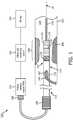
- Fig. 1 is a diagrammatic schematic view of an ultrasound system 100 according to some embodiments of the present disclosure.
- the system 100 can include an ultrasound device 110, a patient interface module (PIM) 150, an ultrasound processing system 160 (sometimes referred to as a computer system), and/or a monitor 170.
- the ultrasound device 110 is structurally arranged (e.g., sized and/or shaped) to be positioned within anatomy 102 of a patient.
- the ultrasound device 110 obtains ultrasound imaging data from within the anatomy 102 and applies ultrasound therapy to the anatomy 102.
- the ultrasound processing system 160 comprises at least a processor and is configured to control the acquisition of ultrasound imaging data and/or the application of ultrasound therapy, and to generate images of the anatomy 102 (using the ultrasound imaging data received via the PIM 150) that is displayed on the monitor 170.
- the processing system 160 is configured to control the ultrasound imaging and application of ultrasound therapy alternatively or simultaneously.
- the processing system can be configured to administer a pharmacological agent.
- the ultrasound imaging and application of ultrasound therapy are performed simultaneously and the pharmacological agent is administered according to a dose that is determined based on real time ultrasound imaging data.
- the ultrasound device 110 can be a catheter, a guide catheter, or a guide wire.
- the ultrasound device 110 includes a flexible elongate member 116.
- "elongate member” or “flexible elongate member” includes at least any thin, long, flexible structure structurally arranged (e.g., sized and/or shaped) to be positioned within a lumen 104 (or body lumen) of the anatomy 102.
- a distal portion 114 of the flexible elongate member 116 is positioned within the lumen 104, while a proximal portion 112 of the flexible elongate member 116 is positioned outside of the body of the patient.
- the flexible elongate member 116 can include a longitudinal axis LA.
- the longitudinal axis LA can be a central longitudinal axis of the flexible elongate member 116.
- the flexible elongate member 116 can include one or more polymer/plastic layers formed of various grades of nylon, Pebax, polymer composites, polyimides, and/or Teflon.
- the flexible elongate member 116 can include one or more layers of braided metallic and/or polymer strands. The braided layer(s) can be tightly or loosely braided in any suitable configuration, including any suitable per in count (pic).
- the flexible elongate member 116 can include one or more metallic and/or polymer coils.
- All or a portion of the flexible elongate member 116 may have any suitable geometric cross-sectional profile (e.g., circular, oval, rectangular, square, elliptical, etc.) or non-geometric cross-sectional profile.
- the flexible elongate member 116 can have a generally cylindrical profile with a circular cross-sectional profile that defines an outer diameter of the flexible elongate member 116.
- the outer diameter of the flexible elongate member 116 can be any suitable value for positioning within the anatomy 102, including between approximately 1 Fr (0.33 mm) and approximately 15 Fr (5 mm), including values such as 3.5 Fr, 5 Fr, 7 Fr, 8.2 Fr, 9 Fr, and/or other suitable values both larger and smaller.
- the ultrasound device 110 may or may not include one or more lumens extending along all or a portion of the length of the flexible elongate member 116.
- the lumen of the ultrasound device 110 can be structurally arranged (e.g., sized and/or shaped) to receive and/or guide one or more other diagnostic and/or therapeutic instruments. If the ultrasound device 110 includes lumen(s), the lumen(s) may be centered or offset with respect to the cross-sectional profile of the device 110.
- the ultrasound device 110 is a catheter and includes a lumen at the distal portion 114 of the flexible elongate member 116.
- a guide wire 140 extends through the lumen of the ultrasound device 110 between an exit/entry port 142 and an exit/entry port at a distal end 118 of the flexible elongate member 116.
- the guide wire 140 is a thin, long, flexible structure that is structurally arranged (e.g., sized and/or shaped) to be disposed within the lumen 104 of the anatomy 102.
- a medical professional typically first inserts the guide wire 140 into the lumen 104 of the anatomy 102 and moves the guide wire 140 to a desired location within the anatomy 102, such as adjacent to an occlusion 106.
- the guide wire 140 facilitates introduction and positioning of one or more other diagnostic and/or therapeutic instruments, including the ultrasound device 110, at the desired location within the anatomy 102.
- the ultrasound device 110 moves through the lumen 104 of the anatomy 102 along the guide wire 140.
- the lumen of the ultrasound device 110 can extend along the entire length of the flexible elongate member 116.
- the exit/entry port 142 is positioned proximally of ultrasound components 120, 130, and 145 of the ultrasound device 110.
- the exit/entry port 142, the exit/entry port at the distal end 118, and/or the lumen of the ultrasound device 110 is positioned distally of the ultrasound components 120, 130, and 145.
- the ultrasound device 110 is not used with a guide wire, and the exit/entry port 142 can be omitted from the ultrasound device 110.
- the assembly that includes the ultrasound components 120, 130, and 145 is referred to as the transducer assembly 200.
- the ultrasound components 120, 130 and 145 can sometimes be structures other than ultrasound transducers or an ultrasound transducer arrays and therefore can also be referred to as ultrasound structures 120, 130 and 145.
- the anatomy 102 may represent any fluid-filled or surrounded structures, both natural and man-made.
- the anatomy 102 can be within the body of a patient. Fluid can flow through the lumen 104 of the anatomy 102.
- the ultrasound device 110 can be referenced as an intraluminal device.
- the anatomy 102 can be a vessel, such as a blood vessel, in which blood flows through the lumen 104.
- the ultrasound device 110 can be referenced as an intravascular device.
- the blood vessel is an artery or a vein of a patient's vascular system, including cardiac vasculature, peripheral vasculature, neural vasculature, renal vasculature, and/or any other suitable anatomy/lumen inside the body.
- the anatomy 102 can be tortuous in some instances.
- the device 110 may be used to examine any number of anatomical locations and tissue types, including without limitation, organs including the liver, heart, kidneys, gall bladder, pancreas, lungs, esophagus; ducts; intestines; nervous system structures including the brain, dural sac, spinal cord and peripheral nerves; the urinary tract; as well as valves within the blood, chambers or other parts of the heart, and/or other systems of the body.
- the device 110 may be used to examine man-made structures such as, but without limitation, heart valves, stents, shunts, filters and other devices.
- the occlusion 106 of the anatomy 102 is generally representative of any blockage or other structural arrangement that results in a restriction to the flow of fluid through the lumen 104, for example, in a manner that is deleterious to the health of the patient.
- the occlusion 106 narrows the lumen 104 such that the cross-sectional area of the lumen 104 and/or the available space for fluid to flow through the lumen 104 is decreased.
- the anatomy 102 is a blood vessel
- the occlusion 106 may be a result of plaque buildup, including without limitation plaque components such as fibrous, fibro-lipidic (fibro fatty), necrotic core, calcified (dense calcium), blood, fresh thrombus, and/or mature thrombus.
- the occlusion 106 can be referenced as thrombus, a stenosis, and/or a lesion.
- the composition of the occlusion 106 will depend on the type of anatomy being evaluated. Healthier portions of the anatomy 102 may have a uniform or symmetrical profile (e.g., a cylindrical profile with a circular cross-sectional profile). The occlusion 106 may not have a uniform or symmetrical profile. Accordingly, diseased portions of the anatomy 102, with the occlusion 106, will have a non-symmetric and/or otherwise irregular profile. While the anatomy 102 is illustrated in Fig. 1 as having a single occlusion 106, it is understood that the devices, systems, and methods described herein have similar application for anatomy having multiple occlusions.
- the ultrasound device 110 includes ultrasound components 120 and 130 at the distal portion 114 of the flexible elongate member 116.
- the ultrasound components 120 and 130 are configured to emit ultrasonic energy into the anatomy 102 while the ultrasound device 110 is positioned within the lumen 104.
- the two ultrasound components 120 and 130 are distinct.
- the two ultrasound components 120 and 130 are the same ultrasound component or part of the same ultrasound component.
- One of the ultrasound components 120, 130 is configured for diagnostic use, while the other of the ultrasound components 120, 130 is configured for therapeutic use.
- the ultrasound components 120, 130 can emit different frequencies of ultrasonic energy into the anatomy 102 depending on whether the ultrasonic energy is being used for diagnosis, such as imaging, and/or treatment.
- the ultrasound components 120 and/or 130 include ultrasound transducer(s).
- the ultrasound components 120 and/or 130 can be configured to generate and emit ultrasound energy into the anatomy 102 in response to being activated by an electrical signal.
- the ultrasound components 120 and/or 130 include a single ultrasound transducer.
- the ultrasound components 120 and/or 130 include an ultrasound transducer array including more than one ultrasound transducer.
- an ultrasound transducer array can include any suitable number of individual transducers between 2 transducers and 1000 transducers, including values such as 2 transducers, 4 transducers, 36 transducers, 64 transducers, 128 transducers, 500 transducers, 812 transducers, and/or other values both larger and smaller.
- the ultrasound components 120 and/or 130 can be any suitable configuration, such as phased array including a planar array, a curved array, a circumferential array, an annular array, etc.
- the ultrasound component 120 and/or 130 can be a one-dimensional array or a two-dimensional array in some instances.
- the ultrasound components 120 and/ or 130 can be a rotational ultrasound device.
- the active area of the ultrasound components 120 and/or 130 can include one or more transducer materials and/or one or more segments of ultrasound elements (e.g., one or more rows, one or more columns, and/or one or more orientations) that can be uniformly or independently controlled and activated.
- the active area of the ultrasound components 120 and/or 130 can be patterned or structured in various basic or complex geometries.
- the ultrasound components 120 and/or 130 can be disposed in a side-looking orientation (e.g., ultrasonic energy emitted perpendicular and/or orthogonal to the longitudinal axis LA) and/or a forward-looking looking orientation (e.g., ultrasonic energy emitted parallel to and/or along the longitudinal axis LA).
- the ultrasound components 120 and/or 130 is structurally arranged to emit and/or receive ultrasonic energy at an oblique angle relative to the longitudinal axis LA, in a proximal or distal direction.
- ultrasonic energy emission can be electronically steered by selective triggering of one or more transducer elements of the ultrasound component 120 and/or 130.
- the ultrasound transducer(s) of the ultrasound components 120 and/or 130 can be a piezoelectric micro machined ultrasound transducer (PMUT), capacitive micromachined ultrasonic transducer (CMUT), single crystal, lead zirconate titanate (PZT), PZT composite, other suitable transducer type, and/or combinations thereof.
- the manufacturing process for ultrasound transducer(s) can include dicing, kerfing, grinding, sputtering, wafer technologies (e.g., SMA, sacrificial layer deposition), other suitable processes, and/or combinations thereof.
- the ultrasound component 120 is configured to obtain ultrasound imaging data associated with the anatomy 102, such as the occlusion 106.
- the ultrasound imaging data obtained by the ultrasound component 120 can be used by a medical professional to diagnose the patient, including evaluating the occlusion 106 of the anatomy 102.
- the ultrasound component 120 can be configured to both emit ultrasonic energy into the lumen 104 and/or the anatomy 102, and to receive reflected ultrasound echoes representative of fluid and/or tissue of lumen 104 and/or the anatomy 102.
- the ultrasound component 120 can be an ultrasound imaging element, such as an ultrasound transducer and/or an ultrasound transducer array.
- the ultrasound component 120 generates and emits ultrasound energy into the anatomy 102 in response to transmission of an electrical signal to the ultrasound component 120.
- the ultrasound component 120 For imaging, the ultrasound component 120 generates and transmits an electrical signal representative of the received reflected ultrasound echoes from the anatomy 102 (e.g., to the PIM 150).
- the ultrasound component 120 can obtain imaging data associated with intravascular ultrasound (IVUS) imaging, forward looking intravascular ultrasound (FL-IVUS) imaging, intravascular photoacoustic (IVPA) imaging, intracardiac echocardiography (ICE), transesophageal echocardiography (TEE), and/or other suitable imaging modalities.
- IVUS intravascular ultrasound
- FL-IVUS forward looking intravascular ultrasound
- IVPA intravascular photoacoustic
- ICE intracardiac echocardiography
- TEE transesophageal echocardiography
- the center frequency of the ultrasound component 120 can be between 10 MHz and 70 MHz, for example, including values such as 10 MHz, 20 MHz, 40 MHz, 45 MHz, 60 MHz, and/or other suitable values both larger and smaller.
- lower frequencies e.g., 10 MHz, 20 MHz
- Higher frequencies e.g., 45 MHz, 60 MHz
- the frequency of the ultrasound component 120 is tunable.
- the ultrasound component 120 can be tuned to receive wavelengths associated with the center frequency and/or one or more harmonics of the center frequency.
- the frequency of the emitted ultrasonic energy can be modified by the voltage of the applied electrical signal and/or the application of a biasing voltage to the ultrasound component 120.
- the ultrasound component 130 is configured to apply an ultrasound therapy to the anatomy 102, such as the occlusion 106.
- the ultrasound component 130 emits sound waves that damage the structure of the occlusion 106.
- the ultrasound device 110 and/or the ultrasound component 130 can be referenced as a lithotripsy device.
- the ultrasonic energy emitted by the ultrasound component 130 can create micro fractures in the calcium blockage of occlusion 106.
- the ultrasound component 130 can deliver ultrasonic energy in a targeted manner to cause cavitation (e.g., wave force cavitation, thermal cavitation, etc.) of the occlusion 106.
- ultrasound therapy can be applied prior to delivery of a pharmacological agent to the anatomy 102 or simultaneously with the ultrasound theraphy.
- the pharmacological agent can be a thrombolytic agent, a fibrinolytic agent, plasmin, plasmid, tissue plasminogen activator, urokinase, streptokinase, collagenace, hepranoid, anti-thrombin drug, any other suitable drug, and/or combinations thereof.
- Pharmacological uptake can be advantageously improved as a result of the degradation of the occlusion 106 by the ultrasonic energy.
- the ultrasound imaging, ultrasound treatment and administering the pharmacological agent occurs simultaneously. Based on the real time ultrasound imaging data the ultrasound treatment parameters may be adapted, as well as dosing the pharmacological agent.
- the occlusion 106 is imaged with the ultrasound as ultrasound treatment is commenced. At the initial phase a steady dose of pharmacological agent is released.
- micro fractures appear in the occlusion, which change the echogenicity of the occlusion in the ultrasound image, based on which the dose of the pharmacological agent is updated, as a higher dose of the agent can more effectively interact with the occlusion through the micro fractures.
- the occlusion material is dissolved through the combined treatment, the occlusion shrinks, which is detectible on the ultrasound imaging data.
- the dose of the pharmacological agent can be at that moment reduced and administered at a rate that is necessary, based on the size and the echogenic characteristic of the occlusion in real time. Accordingly, the efficacy of the treatment and the health of the patient is improved.
- the ultrasound component 130 is an ultrasound element, such as an ultrasound transducer and/or ultrasound transducer array.
- the ultrasound component 130 can be configured to generate and emit ultrasound energy into the anatomy 102 in response to transmission of an electrical signal to the ultrasound component 130.
- the ultrasound component 130 need not be configured to receive ultrasonic echoes reflected the anatomy 102 and generate a representative electrical signal.
- the ultrasound component 130 is not an ultrasound element that generates ultrasound energy. Rather, the ultrasound components 130 can be an intermediate component that is configured to deliver ultrasound energy generated by an ultrasound component separate from the ultrasound device 110 (e.g., an external ultrasound transducer positioned outside of the body of the patient).
- the center frequency of the ultrasound component 130 can be between 1 kHz and 5 MHz, for example, including values such as 50 kHz, 500 kHz, 1 MHz, 3 MHz, and/or other suitable values both larger and smaller.
- the frequency of the ultrasound component 130 is tunable.
- the frequency of the emitted ultrasonic energy can be modified by the voltage of the applied electrical signal and/or the application of a biasing voltage to the ultrasound component 130.
- the ultrasound components 120 and 130 can be configured to generate and emit ultrasound energy, and to generate electrical signals representative of the received ultrasound echoes.
- One of the ultrasound components 120, 130 can be operated in diagnostic and/or imaging mode (generates and emits ultrasound energy, and generates electrical signals representative of the received ultrasound echoes), while the other of the ultrasound components 120, 130 is operated in therapeutic mode (generates and/or emits ultrasound energy).
- the ultrasound device 110 includes a treatment component 145.
- the treatment component 145 can include a balloon, a stent, a needle, an ablation electrode, mechanical cutting component, a rotational cutting device, an aspiration device, and/or other suitable devices.
- the treatment component 145 can be a targeted drug delivery device, a drug coated balloon, a drug coated stent, and/or other suitable device configured to deliver a pharmacological agent to the anatomy 102, such as the occlusion 106.
- the pharmacological agent can be delivered to the anatomy 102 by the treatment component 145 after the ultrasound therapy is applied to the anatomy 102 by the ultrasound component 130.
- the ultrasound device 110 omits the treatment component 145.
- the components 120, 130, and/or 145 in one compact transducer assembly 200 because doing so can minimize the length of a relatively stiffer segment of the flexible elongate member 116.
- the ultrasound components 120, 130, and/or 145 are positioned at the distal portion of the flexible elongate member 116.
- the relative positioning of the ultrasound components 120, 130, and/or 145 can vary in different embodiments.
- the diagnostic and/or imaging ultrasound component 120 is positioned proximally of the therapeutic ultrasound component 130.
- the therapeutic ultrasound component 130 is positioned proximally of the diagnostic and/or imaging ultrasound component 120.
- the treatment component 145 can be positioned proximally of the ultrasound components 120 and/or 130, distally of the ultrasound components 120 and/or 130, or between the ultrasound components 120 and/or 130.
- the ultrasound components 120 and/or 130 can include one or more electrical conductors extending along the length from the flexible elongate member 116.
- the electrical conductor(s) are in communication with the ultrasound components 120, 130 at the distal portion 114, and an interface 156 at the proximal portion 112.
- the electrical conductors carry electrical signals between the ultrasound processing system 160 and the ultrasound components 120, 130.
- activation and/or control signals can be transmitted from the ultrasound processing system 160 to the ultrasound components 120, 130 via the electrical conductors.
- Electrical signals representative of the reflected ultrasound echoes can be transmitted from the ultrasound components 120 and/or 130 to the ultrasound processing system 160 via the electrical conductors.
- the same electrical conductors can be used for communication between the ultrasound processing system 160 and the ultrasound components 120 and/or 130.
- different electrical conductors of the ultrasound device 110 can be used for communication between the ultrasound processing system 160 and the ultrasound component 120, and between the ultrasound processing system 160 and the ultrasound component 130.
- the ultrasound device 110 includes an interface 156 at the proximal portion 112 of the flexible elongate member 116.
- the interface 156 can include a handle.
- handle can include one or more actuation mechanisms to control movement of the device 110, such as deflection of the distal portion 114.
- the interface 156 can include a telescoping mechanism that allows for pullback of the device 110 through the lumen.
- the interface 156 can include a rotation mechanism to rotate one or more components of the device 110 (e.g., the flexible elongate member 116, the ultrasound components 120, 130).
- the interface 156 includes a user interface component (e.g., one or more buttons, a switch, etc.) for a medical professional to selectively activate the ultrasound component 120 for imaging or the ultrasound component 130 for therapy.
- a user interface component of the PIM 150, the ultrasound processing system 160 and/or the monitor 170 allows a medical profession to selectively activate the ultrasound component 120 for imaging or the ultrasound component 130 for therapy.
- a conduit including, e.g., electrical conductors, extends between the interface 156 and the connector 108.
- the connector 108 can be configured to mechanically and/or electrically couple the device 110 to the PIM 150.
- the ultrasound processing system 160, the PIM 150, and/or the intravascular device 110 can include one or more controllers.
- the controllers can be integrated circuits, such as application specific integrated circuits (ASIC), in some embodiments.
- ASIC application specific integrated circuits
- the controllers can be configured to select the particular transducer element(s) to be used for transmit and/or receive, to provide the transmit trigger signals to activate the transmitter circuitry to generate an electrical pulse to excite the selected transducer element(s), and/or to accept amplified echo signals received from the selected transducer element(s) via amplifiers of controllers.
- Multiple ASIC configurations with various numbers of master circuits and slave circuits can be used to create a single ultrasound wave or multi-firing ultrasound wave device.
- the PIM 150 performs preliminary processing of the ultrasound echo data prior to relaying the data to the computer or console 106. In examples of such embodiments, the PIM 150 performs amplification, filtering, and/or aggregating of the data. In an embodiment, the PIM 150 also supplies high- and low-voltage DC power to support operation of the ultrasound device 110 including circuitry associated with the ultrasound components 120 and/or 130.
- the PIM 150 can be an isolation device as, in various surgical settings, patient safety requirements mandate physical and electrical isolation of the patient from one or more high voltage components.
- the ultrasound processing system 160 receives imaging data (e.g., electrical signals representative of the ultrasound echo data) from the ultrasound component 120 by way of the PIM 150.
- the ultrasound processing system 160 can include processing circuit, such as processor and/or memory.
- the ultrasound processing system 160 processes the data to reconstruct an image of the anatomy.
- the ultrasound processing system 160 outputs image data such that an image of the anatomy 102, such as a cross-sectional IVUS image of a vessel, is displayed on the monitor 170.
- the ultrasound processing system 160 and/or the monitor 170 can include one or more user interface elements (e.g., touchscreen, keyboard, mouse, virtual buttons on a graphical user interface, physical buttons, etc.) to allow a medical professional to control the device 110, including one or more parameters of the ultrasound components 120, 130.
- user interface elements e.g., touchscreen, keyboard, mouse, virtual buttons on a graphical user interface, physical buttons, etc.
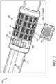
- the transducer assembly 200 includes the ultrasound component 130.
- the ultrasound component is a transducer array and is therefore sometimes referred to as the transducer array 130.
- the transducer array 130 includes a plurality of subarrays 300.
- the subarrays 300 are rectangular in shape and positioned side-by-side next to one another to form the transducer array 130.
- each of the subarrays 300 includes a plurality of transducers 350.
- a subarray 300 can include 4 to 32 transducers 350. Further, in some implementations, the transducers 350 are mounted on a substrate. In some instances, the substrate is planar. In some other instances, the substrate is a semiconductor substrate, such as a silicon substrate. In still other instances, the substrate is a glass substrate.
- a support structure 240 is formed over the transducer array 130 increase robustness of the transducer assembly 200 while maintaining the pliability thereof.
- the support structure 240 can be selected from biocompatible plastics, such as low-durameter PEBAX or nylon and/or super elastic alloys.
- the support structure 240 can be formed over the transducer array through molding, adhesive filling, welding, and heat shrinking.
- the transducer array 130 is filled with a flexible matching layer.
- the flexible matching layer can be a low-durameter plastic over-molded over the transducer array 130 or a saline solution can be used to fill the space between the transducer array 130 and the support structure 240.
- the subarrays 300 are interconnected by flexible circuits 400.
- the flexible circuits 400 connect subarrays 300 along a direction parallel to the longitudinal axis LA of the flexible elongate member 116 and a direction around a circumference of the longitudinal axis LA.
- the transducer assembly 200 includes a connection interface 220.
- the connection interface 220 includes conductive traces, distal ends of which are connected to each of the subarrays 300.
- the proximal end of the connection interface 220 is connected to a control circuit 206.
- the control circuit 206 includes a plurality of control logic dies mounted on a flexible circuit. The control circuit 206 transmits and receives electrical signals to and from the ultrasound processing system 160 shown in Fig.
- the control circuit 206 activates and controls the transducer array 130.
- the control circuit 206 controls the transducer array 130 on a subarray level. That is, the control circuit 206 can selectively activate one or more subarrays 300 at a time. For example, in cases where the transducer array 130 is separated into two or more segments, the control circuit 206 can activate and control these segments separately.
- the transducers 350 can be capacitive micromachined ultrasound transducers (CMUTs) or piezoelectric micromachined ultrasound transudcers (PMUTs).
- CMUTs capacitive micromachined ultrasound transducers
- PMUTs piezoelectric micromachined ultrasound transudcers
- the transducer 350 includes a diaphragm that is formed over a vacuum gap in a dielectric layer on a substrate, usually made of silicon.
- the CMUT further includes an electrode over the diaphragm and another electrode across the air gap from the diaphragm.
- the diaphragm of the CMUT can be excited by an alternating current (AC) electrical signal across the electrodes to emit an ultrasound pulse.
- AC alternating current
- the CMUT operates at a higher frequency or a higher frequency range when the amplitude of the electrical signal is greater.
- an ultrasound pulse can cause deflection of the diaphragm into or away from the air gap, resulting in a change in capacitance across the electrodes.
- properties of the ultrasound pulse can be determined.
- a direct current (DC) bias voltage can be applied across the electrodes of the CMUT to pre-tension the diaphragm. Based on the level of the bias voltage, the diaphragm can be subject to different level of pre-tension. In general, the higher the tension present in the diaphragm, the higher the frequency at which the CMUT emits.
- the subarray 300 includes a plurality of CMUT transducer 350.
- the bias voltage can be applied to the whole or part of the transducer array 130 by the control circuit 206 (shown in Fig. 2 ) or by the ultrasound processing system 160 via electrical conductors of the conductive element 218.
- the effective size of the subarray 300 can be enlarged by connecting the diaphragms of the transducers 350 therein and operating them in parallel. That is, the frequency or frequency range at which the subarray 300 becomes lower when more CMUT transducers 350 in the subarray 300 operate in parallel to increase the effective size of the subarray 300.
- the CMUT transducer 350 includes features described in U.S. Patent Application No.
- the transducer 350 includes a well located in a substrate and a piezoelectric transducer membrane disposed over the well.
- the piezoelectric transducer member includes a top electrode and a bottom electrode.
- the well is at least partially filled with a backing material.
- the piezoelectric transducer member can be deflected by an electrical signal applied across the top and bottom electrodes to emit an ultrasound pulse. Reversely, an ultrasound pulse can cause deformation of the piezoelectric transducer membrane, resulting in a change of voltage across the top and bottom electrodes.
- the frequency or frequency range at which the PMUT emits the ultrasound pulse depends on the thickness and material of the piezoelectric transducer membrane and thickness and material of the backing material.
- the PMUT operates at a higher frequency or a higher frequency range if the thickness of the piezoelectric transducer membrane and the backing material is reduced. In some instances, the PMUT operates at a higher frequency or a higher frequency range if the piezoelectric transducer membrane is made of a more rigid material.
- each of the subarrays 300 in Fig. 2-5 includes 12 transducers 350.
- a subarray 300 can include 4 to 32 transducers 350.
- the subarrays 300 are interconnected along the longitudinal axis LA of by flexible circuits 400A and are interconnected circumferentially around the longitudinal axis LA by flexible circuits 400B.
- the subarrays 300 are electrically connected to the control circuit 206 via the connection interface 220.
- all transducers 350 in the subarrays 300 of the transducer array 130 are all PMUTs.
- all transducers 350 in the subarrays 300 of the transducer array 130 are CMUTs.
- the control circuit 206 can transmit a first electrical signal to the transducer array 130 such that the transducer array 130 operates at a first frequency range to obtain ultrasound imaging data of a target site (such as occlusion 106 within a body lumen 104; and the control circuit 206 can transmit a second electrical signal to the transducer array 130 such as the transducer array 130 operates at a second frequency range to apply an ultrasound therapy within the body lumen 104.
- the first electrical signal has a higher amplitude or higher voltage than the second electrical signal.
- the first frequency falls between 10MHz and 70 MHz and the second frequency fall between 1KHz to 20MHz, and in some cases, between 1KHz and 5MHz.
- the first frequency range has a first median and the second frequency range has a second median. The first median is higher than the second median.
- the transducer array 130 in response to the first electrical signal, operates at the first frequency to function as an ultrasound imaging device. In addition, in response to the second electrical signal, the transducer array 130 operates at the second frequency to function an ultrasound therapy applicator.
- the control circuit 206 or a voltage source external to the control circuit 206 can also subject the CMUT transducers 350 to a bias voltage such that the diaphragms of the transducers 350 are pre-deflected or pre-tensioned to emit ultrasound pulses at a higher frequency.
- the control circuit 206 when the control circuit 206 transmits the first electrical signal to the transducer array 130, the control circuit 206 can simultaneously subject the transducer array 130 to the bias voltage.
- the transducer array 130 includes a proximal half 3000 and a distal half 4000, with each half being cylindrical in shape and positioned circumferentially around the longitudinal axis LA.
- the control circuit 206 can activate and control the proximal half 3000 and the distal half 4000 separately.
- the transducer array 130 includes CMUT transducers 350 throughout or the PMUT transducer 350 throughout.
- the control circuit 206 can transmit the first electrical signal to the proximal half 3000 and the second electrical signal to the distal half 4000.
- the proximal half 3000 includes PMUT transducers 350 and the distal half 4000 includes CMUT transducers 350.
- the proximal half 3000 includes CMUT transducers 350 and the distal half 4000 includes PMUT transducers 350.
- all transducers 350 in the transducer array 130 are CMUTs.
- the proximal half 3000 is subject to a first bias voltage and the distal half 4000 is subject to a second bias voltage. The first bias is different from the second bias.
- the first bias is zero volts (no bias) and the second bias is a non-zero bias, which pre-tensions the diaphragms of the CMUT transducers so that the transducers operate at a higher frequency or a higher frequency range.
- FIG. 5 Shown therein is a diagrammatic enlarged view of the segment of subarrays 300 of the transducer array 130, according to aspects of the present disclosure.
- first subarrays 300A and second subarrays 300B are positioned alternately next to one another.
- first subarrays 300A are distributed evenly across the transducer array 130 and so are the second subarrays 300B.
- the first subarrays 300A and the second subarrays 300B include CMUT transducers 350 throughout and the control circuit 206 is configured to transmit a first electrical signal to the first subarrays 300A and a second electrical signal to the second subarrays 300B.
- the CMUT transducers 350 operate at the first frequency range to obtain ultrasound imaging data.
- the CMUT transducers 350 are operable at the second frequency range to apply an ultrasound therapy.
- the transducer 130 includes CMUT transducers 350 throughout and the control circuit 206 can selectively subject the first subarrays 300A to a first bias and the second subarrays to a second bias.
- the first bias is different from the second bias.
- the first bias is zero.
- the first subarrays 300A include PMUT transducers 350 throughout and the second subarrays 300B include CMUT transducers 350 throughout.
- the ultrasound device 110 includes a treating component 145 in some embodiments.
- the treatment component 145 can include a balloon, a stent, a needle, an ablation electrode, mechanical cutting component, a rotational cutting device, an aspiration device, and/or other suitable devices.
- the treatment component 145 can be a targeted drug delivery device, a drug coated balloon, a drug coated stent, and/or other suitable device configured to deliver a pharmacological agent to a target site in the anatomy 102, such as the occlusion 106.
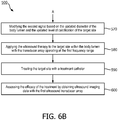
- Figs. 6A and 6B show a flow diagram of a method 500 of treating a target site, such as the occlusion 106 in Fig. 1 within a body lumen of a patient, according to aspects of the present disclosure.
- the method 500 includes operations 510, 520, 530, 540, 550, 560, 570, 580, 590, and 600.
- the operations of method 500 will be described with reference to Figs. 1 and 2 .
- ultrasound imaging data of the body lumen 104 is obtained with use of the transducer array 130 operating at a first frequency range.
- the transducer array 130 is disposed at the distal portion 114 of the flexible elongate member 116 of the intraluminal ultrasound device 110.
- the flexible elongate member 116 is configured to be positioned within the body lumen 104 of a patient.
- the transducer array 130 is circumferentially positioned around the longitudinal axis LA of the flexible elongate member 116 and is configured to obtain ultrasound imaging data of the body lumen 104 in response to a first electrical signal.
- the transducer array 130 can also apply an ultrasound therapy in response to a second electrical signal.
- a diameter of the body lumen 104 and a level of calcification of the target site are determined based on the ultrasound imaging data obtained at operation 510.
- a target site such as occlusion 106 in Fig. 1
- the level of calcification of the target site can be determined.
- VH virtual histology
- a second electrical signal is modified based on the diameter of the body lumen 104 and the level of calcification of the target site determined at operation 520.
- effective treatment of the target site requires an ultrasound therapy involving ultrasound pulses with different frequencies, different pulse amplitudes, and different pulse lengths.
- an ultrasound processing system 160 in communication of the ultrasound device 110 can modify the second electrical signal to be transmitted to the transducer array 130 for effective treatment of the target site.
- an ultrasound therapy is applied to the target site within the body lumen 104 with the transducer array 130, operating in response to the modified second electrical signal.
- ultrasound imaging data of the body lumen 104 is obtained using the transducer array 130, which operates at the first frequency range in response to the first electrical signal.
- ultrasound imaging data of the lumen 104 is obtained again by the transducer array 130, in response to the first electrical signal.
- an updated diameter of the body lumen 104 and an updated level of calcification of the target site is determined by the ultrasound processing system 160, based on the ultrasound imaging data obtained at operation 550.
- the diameter of the body lumen 104 and the level of calcification of the target site may have reduced.
- ultrasound imaging data of the lumen 104 is obtained again with use of the transducer array 130.
- the second electrical signal is again modified by the ultrasound processing system 160 based on the updated diameter of the body lumen 104 and the updated level of calcification of the target site. Based on parameters stored in the ultrasound processing system 160, the ultrasound processing system 160 can determine whether further ultrasound therapies are required. If no further ultrasound therapies are required, method 500 would skip operation 580 and proceed directly to operation 590. If further ultrasound therapies are required, the ultrasound processing system 160 modifies the second electrical signal for effective treatment of the target site.
- the ultrasound therapy is applied to the target site within the body lumen 104 while the transducer array 130 operates at a second frequency range in response to the modified second electrical signal.
- the target site is treated with the treatment component 145 disposed on the distal portion 114 of the ultrasound device 110.
- the treatment component 145 is incorporated in the transducer assembly 200. In some other instances, the treatment component 145 is separate from the transducer assembly 200 and is distal to the transducer assembly 200.
- ultrasound imaging data of the body lumen 104 is obtained using the first ultrasound transducer array 124B.
- the systems, devices, and methods of the present disclosure can include features described in U.S. Provisional App. No. 62/545944 , filed on an even date herewith, U.S. Provisional App. No. 62/545951 , filed on an even date herewith, U.S. Provisional App. No. 62/545927 , filed on an even date herewith, and/or U.S. Provisional App. No. 62/545888 , filed on an even date herewith.
Claims (15)
- Dispositif intraluminal à ultrasons, comprenant :un élément allongé (116) flexible conçu pour être positionné dans une lumière corporelle (104) d'un patient, l'élément allongé (116) flexible comprenant une partie distale (114) et un axe longitudinal (LA) ; etun réseau de transducteurs (130) disposé au niveau de la partie distale (114) de l'élément allongé (116) flexible et positionné circonférentiellement autour de l'axe longitudinal (LA) de l'élément allongé (116) flexible, dans lequel le réseau de transducteurs (130) comprend une pluralité de transducteurs à ultrasons micro-usinés (MUT) (350),dans lequel le réseau de transducteurs (130) est conçu pour obtenir des données d'imagerie par ultrasons de la lumière corporelle (104) en réponse à un premier signal électrique,dans lequel le réseau de transducteurs (130) est conçu pour appliquer une thérapie par ultrasons dans la lumière corporelle (104) en réponse à un second signal électrique ; etcaractérisé en ce que la pluralité de MUT (350) comprend :a) une première pluralité de transducteurs à ultrasons micro-usinés piézoélectriques (PMUT) et une seconde pluralité de PMUT,dans lequel chaque PMUT de la première pluralité de PMUT comprend une membrane de transducteur d'une première épaisseur, etdans lequel chaque PMUT de la seconde pluralité de PMUT comprend une membrane de transducteur d'une seconde épaisseur, différente de la première épaisseur ;ou
b) une première pluralité de transducteurs à ultrasons micro-usinés capacitifs (CMUT) et une seconde pluralité de CMUT,dans lequel chaque transducteur de la première pluralité de CMUT est conçu pour fonctionner sous une première tension de polarisation, etdans lequel chaque transducteur de la seconde pluralité de CMUT est conçu pour fonctionner sous une seconde tension de polarisation, différente de la première tension de polarisation. - Dispositif intraluminal à ultrasons selon la revendication 1, dans lequel le réseau de transducteurs (130), en réponse au premier signal électrique, est conçu pour fonctionner dans une première plage de fréquences et le réseau de transducteurs (130), en réponse au second signal électrique, est conçu pour fonctionner dans une seconde plage de fréquences, différente de la première gamme de fréquences.
- Dispositif intraluminal à ultrasons selon la revendication 1, dans lequel la pluralité de MUT (350) comprend une pluralité de sous-réseaux de MUT inter-connectés par une pluralité de circuits (400) flexibles.
- Dispositif intraluminal à ultrasons selon la revendication 1, comprenant en outre un circuit de commande (206) en communication avec le réseau de transducteurs (130), le circuit de commande (206) étant conçu pour générer le premier signal électrique et le second signal électrique.
- Dispositif intraluminal à ultrasons selon la revendication 4, dans lequel une tension du premier signal électrique est différente d'une tension du second signal électrique.
- Dispositif intraluminal à ultrasons selon la revendication 4, dans lequel l'unité de commande (206) est conçue pour commander les première et seconde tensions de polarisation.
- Dispositif intraluminal à ultrasons selon la revendication 1, dans lequel la première ou la seconde tension de polarisation est de zéro volt.
- Dispositif intraluminal à ultrasons selon la revendication 1, dans lequel la pluralité de MUT (350) comprend les première et seconde pluralités de transducteurs à ultrasons micro-usinés capacitifs (CMUT) et les première et seconde pluralités de transducteurs à ultrasons micro-usinés piézoélectriques (PMUT).
- Système de traitement d'un site cible dans une lumière corporelle (104) d'un patient comprenant :un dispositif intraluminal à ultrasons selon l'une quelconque des revendications 1 à 8 ;un système de traitement (160) conçu :pour commander l'acquisition des données d'imagerie par ultrasons et l'application de la thérapie par ultrasons à l'aide du dispositif intraluminal à ultrasons, etpour générer des images de la lumière corporelle (104) comprenant le site cible.
- Système selon la revendication 9, dans lequel le système de traitement (160) est conçu pour commander le dispositif intraluminal à ultrasons pour alterner l'imagerie par ultrasons avec l'application d'une thérapie par ultrasons.
- Système selon la revendication 9, dans lequel le système de traitement (160) est conçu pour commander le dispositif intraluminal à ultrasons pour imager par ultrasons et appliquer une thérapie par ultrasons de manière simultanée.
- Système selon la revendication 11, dans lequel le système de traitement (160) est conçu pour administrer un agent pharmacologique au site cible à travers une lumière du dispositif intraluminal à ultrasons.
- Système selon la revendication 12, dans lequel le système de traitement (160) est conçu pour administrer l'agent pharmacologique simultanément avec l'application d'une thérapie par ultrasons.
- Système selon la revendication 13, dans lequel la dose de l'agent pharmacologique est variable pendant l'application d'une thérapie par ultrasons.
- Système selon la revendication 14, dans lequel la dose est basée sur les données d'imagerie par ultrasons du site cible.
Applications Claiming Priority (2)
| Application Number | Priority Date | Filing Date | Title |
|---|---|---|---|
| US201762545954P | 2017-08-15 | 2017-08-15 | |
| PCT/EP2018/071562 WO2019034500A1 (fr) | 2017-08-15 | 2018-08-08 | Dispositif ultrasonore intraluminal à fréquence réglable |
Publications (2)
| Publication Number | Publication Date |
|---|---|
| EP3668411A1 EP3668411A1 (fr) | 2020-06-24 |
| EP3668411B1 true EP3668411B1 (fr) | 2021-01-13 |
Family
ID=63407179
Family Applications (1)
| Application Number | Title | Priority Date | Filing Date |
|---|---|---|---|
| EP18762018.2A Active EP3668411B1 (fr) | 2017-08-15 | 2018-08-08 | Dispositif ultrasonore intraluminal à fréquence réglable |
Country Status (5)
| Country | Link |
|---|---|
| US (1) | US11589835B2 (fr) |
| EP (1) | EP3668411B1 (fr) |
| JP (1) | JP7203824B2 (fr) |
| CN (1) | CN111212606B (fr) |
| WO (1) | WO2019034500A1 (fr) |
Families Citing this family (9)
| Publication number | Priority date | Publication date | Assignee | Title |
|---|---|---|---|---|
| US11298106B2 (en) * | 2018-08-31 | 2022-04-12 | Covidien Lp | Minimally-invasive surgical instrument including three-dimensional (3D) ultrasound imaging and focused ultrasound treatment capabilities |
| EP3886737A4 (fr) | 2018-11-28 | 2022-08-24 | Histosonics, Inc. | Systèmes et procédés d'histotrypsie |
| US20220305296A1 (en) | 2019-05-24 | 2022-09-29 | The University Of Melbourne | Neurostimulation using endoluminal focussed ultrasound |
| JP7233316B2 (ja) * | 2019-06-21 | 2023-03-06 | 朝日インテック株式会社 | ガイドワイヤ、ガイドワイヤシステムおよびイメージングガイドワイヤ |
| EP4096782A4 (fr) | 2020-01-28 | 2024-02-14 | Univ Michigan Regents | Systèmes et procédés d'immunosensibilisation par histotripsie |
| IT202000018322A1 (it) * | 2020-07-28 | 2022-01-28 | Opconsulting S R L | Apparecchio medico a emissione di onde ultrasoniche |
| JP2022029325A (ja) * | 2020-08-04 | 2022-02-17 | 国立大学法人大阪大学 | フレキシブル超音波発生装置 |
| CN113331908A (zh) * | 2021-03-16 | 2021-09-03 | 上海玮沐医疗科技有限公司 | 一种双球囊超声导管的血栓抽吸系统及其应用 |
| WO2023165839A1 (fr) * | 2022-03-03 | 2023-09-07 | Shl Medical Ag | Détecteur de site d'administration et dispositif d'administration de médicament qui comprend le détecteur de site d'administration |
Family Cites Families (32)
| Publication number | Priority date | Publication date | Assignee | Title |
|---|---|---|---|---|
| US5558092A (en) * | 1995-06-06 | 1996-09-24 | Imarx Pharmaceutical Corp. | Methods and apparatus for performing diagnostic and therapeutic ultrasound simultaneously |
| US5857974A (en) * | 1997-01-08 | 1999-01-12 | Endosonics Corporation | High resolution intravascular ultrasound transducer assembly having a flexible substrate |
| US6381350B1 (en) | 1999-07-02 | 2002-04-30 | The Cleveland Clinic Foundation | Intravascular ultrasonic analysis using active contour method and system |
| US6740039B1 (en) * | 1999-08-20 | 2004-05-25 | Koninklijke Philips Electronics N.V. | Methods and apparatus for displaying information relating to delivery and activation of a therapeutic agent using ultrasound energy |
| US6200268B1 (en) | 1999-09-10 | 2001-03-13 | The Cleveland Clinic Foundation | Vascular plaque characterization |
| EP1377321A4 (fr) * | 2001-02-23 | 2006-01-11 | Bristol Myers Squibb Co | Antagonistes des recepteurs eboueurs des macrophages marques de maniere detectable pour l'identification d'une atherosclerose et d'une plaque vulnerable par imagerie |
| US7074188B2 (en) | 2002-08-26 | 2006-07-11 | The Cleveland Clinic Foundation | System and method of characterizing vascular tissue |
| US7359554B2 (en) | 2002-08-26 | 2008-04-15 | Cleveland Clinic Foundation | System and method for identifying a vascular border |
| US7175597B2 (en) | 2003-02-03 | 2007-02-13 | Cleveland Clinic Foundation | Non-invasive tissue characterization system and method |
| JP2004290548A (ja) * | 2003-03-28 | 2004-10-21 | Toshiba Corp | 画像診断装置、診断・治療装置及び診断・治療方法 |
| US7215802B2 (en) | 2004-03-04 | 2007-05-08 | The Cleveland Clinic Foundation | System and method for vascular border detection |
| US20060036167A1 (en) * | 2004-07-03 | 2006-02-16 | Shina Systems Ltd. | Vascular image processing |
| US7553284B2 (en) * | 2005-02-02 | 2009-06-30 | Vaitekunas Jeffrey J | Focused ultrasound for pain reduction |
| LT1912749T (lt) * | 2005-07-26 | 2021-10-25 | Surf Technology As | Dvigubos dažnių juostos ultragarso daviklio matricos |
| US20070073135A1 (en) * | 2005-09-13 | 2007-03-29 | Warren Lee | Integrated ultrasound imaging and ablation probe |
| WO2007115283A2 (fr) * | 2006-04-04 | 2007-10-11 | Kolo Technologies, Inc. | Modulation dans des transducteurs ultrasonores micro-usinés |
| US20080221448A1 (en) * | 2007-03-07 | 2008-09-11 | Khuri-Yakub Butrus T | Image-guided delivery of therapeutic tools duing minimally invasive surgeries and interventions |
| US9089287B2 (en) * | 2008-12-30 | 2015-07-28 | St. Jude Medical, Atrial Fibrillation Division, Inc. | Image-guided ablation system and method for monitoring an ablation procedure |
| JP5541946B2 (ja) * | 2010-02-26 | 2014-07-09 | オリンパス株式会社 | 超音波治療装置 |
| US9192790B2 (en) * | 2010-04-14 | 2015-11-24 | Boston Scientific Scimed, Inc. | Focused ultrasonic renal denervation |
| US20130204242A1 (en) * | 2010-10-18 | 2013-08-08 | CardioSonic Ltd. | Ultrasound transceiver and control of a thermal damage process |
| JP5734620B2 (ja) | 2010-10-27 | 2015-06-17 | オリンパス株式会社 | 超音波プローブ装置及びその制御方法 |
| EP2455133A1 (fr) * | 2010-11-18 | 2012-05-23 | Koninklijke Philips Electronics N.V. | Cathéter doté de transducteurs ultrasonores capacitifs micro-usinés dotés d'une mise au point réglable |
| EP2680923A4 (fr) * | 2011-03-04 | 2016-08-03 | Rainbow Medical Ltd | Traitement et surveillance des tissus par application d'énergie |
| RU2657950C2 (ru) * | 2012-04-12 | 2018-06-18 | Конинклейке Филипс Н.В. | Высокоинтенсивный сфокусированный ультразвук с емкостными микромеханическими преобразователями |
| EP2953550B1 (fr) * | 2013-02-08 | 2020-05-20 | Acutus Medical, Inc. | Ensemble cathéter extensible doté d'une carte de circuits imprimés (pcb) flexible |
| WO2014134277A1 (fr) * | 2013-02-28 | 2014-09-04 | Guided Interventions, Inc. | Gaine d'imagerie par ultrasons et procédé associé de traitement par cathéter percutané guidé |
| JP6513674B2 (ja) * | 2013-08-27 | 2019-05-15 | コーニンクレッカ フィリップス エヌ ヴェKoninklijke Philips N.V. | デュアルモードcmutトランスデューサ |
| JP6782691B2 (ja) | 2014-08-01 | 2020-11-11 | コーニンクレッカ フィリップス エヌ ヴェKoninklijke Philips N.V. | 血管内超音波撮像装置、インターフェースアーキテクチャ、及び製造方法 |
| CN107735032B (zh) * | 2015-07-02 | 2021-09-21 | 皇家飞利浦有限公司 | 多模式电容式微加工超声换能器以及相关联的设备、系统和方法 |
| AU2016343928B2 (en) * | 2015-10-30 | 2021-01-28 | Biosense Webster (Israel) Ltd. | Foldable 2-D CMUT-on-CMOS arrays |
| US10856840B2 (en) * | 2016-06-20 | 2020-12-08 | Butterfly Network, Inc. | Universal ultrasound device and related apparatus and methods |
-
2018
- 2018-08-08 CN CN201880066890.2A patent/CN111212606B/zh active Active
- 2018-08-08 WO PCT/EP2018/071562 patent/WO2019034500A1/fr unknown
- 2018-08-08 JP JP2020508570A patent/JP7203824B2/ja active Active
- 2018-08-08 EP EP18762018.2A patent/EP3668411B1/fr active Active
- 2018-08-15 US US15/998,442 patent/US11589835B2/en active Active
Non-Patent Citations (1)
| Title |
|---|
| None * |
Also Published As
| Publication number | Publication date |
|---|---|
| EP3668411A1 (fr) | 2020-06-24 |
| US20190053781A1 (en) | 2019-02-21 |
| WO2019034500A1 (fr) | 2019-02-21 |
| JP7203824B2 (ja) | 2023-01-13 |
| CN111212606A (zh) | 2020-05-29 |
| JP2020531093A (ja) | 2020-11-05 |
| CN111212606B (zh) | 2024-03-01 |
| US11589835B2 (en) | 2023-02-28 |
Similar Documents
| Publication | Publication Date | Title |
|---|---|---|
| EP3668411B1 (fr) | Dispositif ultrasonore intraluminal à fréquence réglable | |
| US8545412B2 (en) | Systems and methods for making and using image-guided intravascular and endocardial therapy systems | |
| US11883235B2 (en) | Phased array imaging and therapy intraluminal ultrasound device | |
| JP2020032241A (ja) | イメージング及び処理デバイス | |
| US11857376B2 (en) | Patient interface module (PIM) powered with wireless charging system and communicating with sensing device and processing system | |
| JP7194733B2 (ja) | デジタル回転患者インターフェースモジュール | |
| EP3668410B1 (fr) | Traitement intracardiaque et dispositif de diagnostic à ultrasons | |
| WO2012112463A2 (fr) | Dispositifs de diagnostic et de thérapie à ultrasons | |
| EP3668597A1 (fr) | Dispositif à ultrasons thérapeutique jetable | |
| CN111065342B (zh) | 用于诊断成像和治疗的腔内超声设备 | |
| US11819360B2 (en) | Intraluminal rotational ultrasound for diagnostic imaging and therapy | |
| JP2020531080A (ja) | 調整可能可撓性/剛性腔内装置 |
Legal Events
| Date | Code | Title | Description |
|---|---|---|---|
| STAA | Information on the status of an ep patent application or granted ep patent |
Free format text: STATUS: UNKNOWN |
|
| STAA | Information on the status of an ep patent application or granted ep patent |
Free format text: STATUS: THE INTERNATIONAL PUBLICATION HAS BEEN MADE |
|
| PUAI | Public reference made under article 153(3) epc to a published international application that has entered the european phase |
Free format text: ORIGINAL CODE: 0009012 |
|
| STAA | Information on the status of an ep patent application or granted ep patent |
Free format text: STATUS: REQUEST FOR EXAMINATION WAS MADE |
|
| 17P | Request for examination filed |
Effective date: 20200316 |
|
| AK | Designated contracting states |
Kind code of ref document: A1 Designated state(s): AL AT BE BG CH CY CZ DE DK EE ES FI FR GB GR HR HU IE IS IT LI LT LU LV MC MK MT NL NO PL PT RO RS SE SI SK SM TR |
|
| AX | Request for extension of the european patent |
Extension state: BA ME |
|
| GRAP | Despatch of communication of intention to grant a patent |
Free format text: ORIGINAL CODE: EPIDOSNIGR1 |
|
| STAA | Information on the status of an ep patent application or granted ep patent |
Free format text: STATUS: GRANT OF PATENT IS INTENDED |
|
| RIC1 | Information provided on ipc code assigned before grant |
Ipc: A61B 18/00 20060101ALN20200713BHEP Ipc: A61N 7/02 20060101ALI20200713BHEP Ipc: A61B 8/00 20060101ALI20200713BHEP Ipc: A61B 8/12 20060101AFI20200713BHEP Ipc: A61B 17/3207 20060101ALN20200713BHEP Ipc: A61N 7/00 20060101ALI20200713BHEP Ipc: A61B 18/14 20060101ALN20200713BHEP Ipc: A61B 17/22 20060101ALN20200713BHEP Ipc: A61M 37/00 20060101ALI20200713BHEP Ipc: A61B 90/00 20160101ALN20200713BHEP |
|
| DAV | Request for validation of the european patent (deleted) | ||
| DAX | Request for extension of the european patent (deleted) | ||
| INTG | Intention to grant announced |
Effective date: 20200805 |
|
| GRAS | Grant fee paid |
Free format text: ORIGINAL CODE: EPIDOSNIGR3 |
|
| GRAA | (expected) grant |
Free format text: ORIGINAL CODE: 0009210 |
|
| STAA | Information on the status of an ep patent application or granted ep patent |
Free format text: STATUS: THE PATENT HAS BEEN GRANTED |
|
| AK | Designated contracting states |
Kind code of ref document: B1 Designated state(s): AL AT BE BG CH CY CZ DE DK EE ES FI FR GB GR HR HU IE IS IT LI LT LU LV MC MK MT NL NO PL PT RO RS SE SI SK SM TR |
|
| REG | Reference to a national code |
Ref country code: GB Ref legal event code: FG4D |
|
| REG | Reference to a national code |
Ref country code: CH Ref legal event code: EP |
|
| REG | Reference to a national code |
Ref country code: IE Ref legal event code: FG4D |
|
| REG | Reference to a national code |
Ref country code: DE Ref legal event code: R096 Ref document number: 602018011893 Country of ref document: DE |
|
| REG | Reference to a national code |
Ref country code: AT Ref legal event code: REF Ref document number: 1353947 Country of ref document: AT Kind code of ref document: T Effective date: 20210215 |
|
| REG | Reference to a national code |
Ref country code: AT Ref legal event code: MK05 Ref document number: 1353947 Country of ref document: AT Kind code of ref document: T Effective date: 20210113 |
|
| REG | Reference to a national code |
Ref country code: NL Ref legal event code: MP Effective date: 20210113 |
|
| REG | Reference to a national code |
Ref country code: LT Ref legal event code: MG9D |
|
| PG25 | Lapsed in a contracting state [announced via postgrant information from national office to epo] |
Ref country code: LT Free format text: LAPSE BECAUSE OF FAILURE TO SUBMIT A TRANSLATION OF THE DESCRIPTION OR TO PAY THE FEE WITHIN THE PRESCRIBED TIME-LIMIT Effective date: 20210113 Ref country code: NO Free format text: LAPSE BECAUSE OF FAILURE TO SUBMIT A TRANSLATION OF THE DESCRIPTION OR TO PAY THE FEE WITHIN THE PRESCRIBED TIME-LIMIT Effective date: 20210413 Ref country code: PT Free format text: LAPSE BECAUSE OF FAILURE TO SUBMIT A TRANSLATION OF THE DESCRIPTION OR TO PAY THE FEE WITHIN THE PRESCRIBED TIME-LIMIT Effective date: 20210513 Ref country code: BG Free format text: LAPSE BECAUSE OF FAILURE TO SUBMIT A TRANSLATION OF THE DESCRIPTION OR TO PAY THE FEE WITHIN THE PRESCRIBED TIME-LIMIT Effective date: 20210413 Ref country code: GR Free format text: LAPSE BECAUSE OF FAILURE TO SUBMIT A TRANSLATION OF THE DESCRIPTION OR TO PAY THE FEE WITHIN THE PRESCRIBED TIME-LIMIT Effective date: 20210414 Ref country code: HR Free format text: LAPSE BECAUSE OF FAILURE TO SUBMIT A TRANSLATION OF THE DESCRIPTION OR TO PAY THE FEE WITHIN THE PRESCRIBED TIME-LIMIT Effective date: 20210113 Ref country code: FI Free format text: LAPSE BECAUSE OF FAILURE TO SUBMIT A TRANSLATION OF THE DESCRIPTION OR TO PAY THE FEE WITHIN THE PRESCRIBED TIME-LIMIT Effective date: 20210113 |
|
| PG25 | Lapsed in a contracting state [announced via postgrant information from national office to epo] |
Ref country code: AT Free format text: LAPSE BECAUSE OF FAILURE TO SUBMIT A TRANSLATION OF THE DESCRIPTION OR TO PAY THE FEE WITHIN THE PRESCRIBED TIME-LIMIT Effective date: 20210113 Ref country code: RS Free format text: LAPSE BECAUSE OF FAILURE TO SUBMIT A TRANSLATION OF THE DESCRIPTION OR TO PAY THE FEE WITHIN THE PRESCRIBED TIME-LIMIT Effective date: 20210113 Ref country code: PL Free format text: LAPSE BECAUSE OF FAILURE TO SUBMIT A TRANSLATION OF THE DESCRIPTION OR TO PAY THE FEE WITHIN THE PRESCRIBED TIME-LIMIT Effective date: 20210113 Ref country code: LV Free format text: LAPSE BECAUSE OF FAILURE TO SUBMIT A TRANSLATION OF THE DESCRIPTION OR TO PAY THE FEE WITHIN THE PRESCRIBED TIME-LIMIT Effective date: 20210113 Ref country code: SE Free format text: LAPSE BECAUSE OF FAILURE TO SUBMIT A TRANSLATION OF THE DESCRIPTION OR TO PAY THE FEE WITHIN THE PRESCRIBED TIME-LIMIT Effective date: 20210113 |
|
| PG25 | Lapsed in a contracting state [announced via postgrant information from national office to epo] |
Ref country code: IS Free format text: LAPSE BECAUSE OF FAILURE TO SUBMIT A TRANSLATION OF THE DESCRIPTION OR TO PAY THE FEE WITHIN THE PRESCRIBED TIME-LIMIT Effective date: 20210513 |
|
| REG | Reference to a national code |
Ref country code: DE Ref legal event code: R097 Ref document number: 602018011893 Country of ref document: DE |
|
| PG25 | Lapsed in a contracting state [announced via postgrant information from national office to epo] |
Ref country code: CZ Free format text: LAPSE BECAUSE OF FAILURE TO SUBMIT A TRANSLATION OF THE DESCRIPTION OR TO PAY THE FEE WITHIN THE PRESCRIBED TIME-LIMIT Effective date: 20210113 Ref country code: EE Free format text: LAPSE BECAUSE OF FAILURE TO SUBMIT A TRANSLATION OF THE DESCRIPTION OR TO PAY THE FEE WITHIN THE PRESCRIBED TIME-LIMIT Effective date: 20210113 Ref country code: SM Free format text: LAPSE BECAUSE OF FAILURE TO SUBMIT A TRANSLATION OF THE DESCRIPTION OR TO PAY THE FEE WITHIN THE PRESCRIBED TIME-LIMIT Effective date: 20210113 |
|
| PGFP | Annual fee paid to national office [announced via postgrant information from national office to epo] |
Ref country code: FR Payment date: 20210826 Year of fee payment: 4 |
|
| PLBE | No opposition filed within time limit |
Free format text: ORIGINAL CODE: 0009261 |
|
| STAA | Information on the status of an ep patent application or granted ep patent |
Free format text: STATUS: NO OPPOSITION FILED WITHIN TIME LIMIT |
|
| PG25 | Lapsed in a contracting state [announced via postgrant information from national office to epo] |
Ref country code: DK Free format text: LAPSE BECAUSE OF FAILURE TO SUBMIT A TRANSLATION OF THE DESCRIPTION OR TO PAY THE FEE WITHIN THE PRESCRIBED TIME-LIMIT Effective date: 20210113 Ref country code: RO Free format text: LAPSE BECAUSE OF FAILURE TO SUBMIT A TRANSLATION OF THE DESCRIPTION OR TO PAY THE FEE WITHIN THE PRESCRIBED TIME-LIMIT Effective date: 20210113 Ref country code: SK Free format text: LAPSE BECAUSE OF FAILURE TO SUBMIT A TRANSLATION OF THE DESCRIPTION OR TO PAY THE FEE WITHIN THE PRESCRIBED TIME-LIMIT Effective date: 20210113 |
|
| 26N | No opposition filed |
Effective date: 20211014 |
|
| PG25 | Lapsed in a contracting state [announced via postgrant information from national office to epo] |
Ref country code: ES Free format text: LAPSE BECAUSE OF FAILURE TO SUBMIT A TRANSLATION OF THE DESCRIPTION OR TO PAY THE FEE WITHIN THE PRESCRIBED TIME-LIMIT Effective date: 20210113 Ref country code: AL Free format text: LAPSE BECAUSE OF FAILURE TO SUBMIT A TRANSLATION OF THE DESCRIPTION OR TO PAY THE FEE WITHIN THE PRESCRIBED TIME-LIMIT Effective date: 20210113 |
|
| REG | Reference to a national code |
Ref country code: CH Ref legal event code: PL |
|
| PG25 | Lapsed in a contracting state [announced via postgrant information from national office to epo] |
Ref country code: MC Free format text: LAPSE BECAUSE OF FAILURE TO SUBMIT A TRANSLATION OF THE DESCRIPTION OR TO PAY THE FEE WITHIN THE PRESCRIBED TIME-LIMIT Effective date: 20210113 |
|
| REG | Reference to a national code |
Ref country code: BE Ref legal event code: MM Effective date: 20210831 |
|
| PG25 | Lapsed in a contracting state [announced via postgrant information from national office to epo] |
Ref country code: LI Free format text: LAPSE BECAUSE OF NON-PAYMENT OF DUE FEES Effective date: 20210831 Ref country code: IT Free format text: LAPSE BECAUSE OF FAILURE TO SUBMIT A TRANSLATION OF THE DESCRIPTION OR TO PAY THE FEE WITHIN THE PRESCRIBED TIME-LIMIT Effective date: 20210113 Ref country code: CH Free format text: LAPSE BECAUSE OF NON-PAYMENT OF DUE FEES Effective date: 20210831 |
|
| PG25 | Lapsed in a contracting state [announced via postgrant information from national office to epo] |
Ref country code: IS Free format text: LAPSE BECAUSE OF FAILURE TO SUBMIT A TRANSLATION OF THE DESCRIPTION OR TO PAY THE FEE WITHIN THE PRESCRIBED TIME-LIMIT Effective date: 20210513 Ref country code: LU Free format text: LAPSE BECAUSE OF NON-PAYMENT OF DUE FEES Effective date: 20210808 |
|
| PG25 | Lapsed in a contracting state [announced via postgrant information from national office to epo] |
Ref country code: IE Free format text: LAPSE BECAUSE OF NON-PAYMENT OF DUE FEES Effective date: 20210808 Ref country code: BE Free format text: LAPSE BECAUSE OF NON-PAYMENT OF DUE FEES Effective date: 20210831 |
|
| PG25 | Lapsed in a contracting state [announced via postgrant information from national office to epo] |
Ref country code: NL Free format text: LAPSE BECAUSE OF NON-PAYMENT OF DUE FEES Effective date: 20210113 Ref country code: CY Free format text: LAPSE BECAUSE OF FAILURE TO SUBMIT A TRANSLATION OF THE DESCRIPTION OR TO PAY THE FEE WITHIN THE PRESCRIBED TIME-LIMIT Effective date: 20210113 |
|
| PG25 | Lapsed in a contracting state [announced via postgrant information from national office to epo] |
Ref country code: HU Free format text: LAPSE BECAUSE OF FAILURE TO SUBMIT A TRANSLATION OF THE DESCRIPTION OR TO PAY THE FEE WITHIN THE PRESCRIBED TIME-LIMIT; INVALID AB INITIO Effective date: 20180808 Ref country code: FR Free format text: LAPSE BECAUSE OF NON-PAYMENT OF DUE FEES Effective date: 20220831 |
|
| PG25 | Lapsed in a contracting state [announced via postgrant information from national office to epo] |
Ref country code: SI Free format text: LAPSE BECAUSE OF FAILURE TO SUBMIT A TRANSLATION OF THE DESCRIPTION OR TO PAY THE FEE WITHIN THE PRESCRIBED TIME-LIMIT Effective date: 20210113 |
|
| PGFP | Annual fee paid to national office [announced via postgrant information from national office to epo] |
Ref country code: GB Payment date: 20230822 Year of fee payment: 6 |
|
| PGFP | Annual fee paid to national office [announced via postgrant information from national office to epo] |
Ref country code: DE Payment date: 20230828 Year of fee payment: 6 |