EP3667782A1 - Lithium ion secondary battery negative electrode material and lithium ion secondary battery - Google Patents
Lithium ion secondary battery negative electrode material and lithium ion secondary battery Download PDFInfo
- Publication number
- EP3667782A1 EP3667782A1 EP18844888.0A EP18844888A EP3667782A1 EP 3667782 A1 EP3667782 A1 EP 3667782A1 EP 18844888 A EP18844888 A EP 18844888A EP 3667782 A1 EP3667782 A1 EP 3667782A1
- Authority
- EP
- European Patent Office
- Prior art keywords
- carbon
- composite material
- mass
- secondary battery
- lithium ion
- Prior art date
- Legal status (The legal status is an assumption and is not a legal conclusion. Google has not performed a legal analysis and makes no representation as to the accuracy of the status listed.)
- Withdrawn
Links
- 229910001416 lithium ion Inorganic materials 0.000 title claims abstract description 41
- HBBGRARXTFLTSG-UHFFFAOYSA-N Lithium ion Chemical compound [Li+] HBBGRARXTFLTSG-UHFFFAOYSA-N 0.000 title claims abstract description 40
- 239000007773 negative electrode material Substances 0.000 title claims abstract description 36
- OKTJSMMVPCPJKN-UHFFFAOYSA-N Carbon Chemical compound [C] OKTJSMMVPCPJKN-UHFFFAOYSA-N 0.000 claims abstract description 175
- 239000002245 particle Substances 0.000 claims abstract description 157
- 239000002131 composite material Substances 0.000 claims abstract description 120
- 229910052799 carbon Inorganic materials 0.000 claims abstract description 101
- 229910052710 silicon Inorganic materials 0.000 claims abstract description 74
- 229910002804 graphite Inorganic materials 0.000 claims abstract description 73
- 239000010439 graphite Substances 0.000 claims abstract description 73
- XUIMIQQOPSSXEZ-UHFFFAOYSA-N Silicon Chemical compound [Si] XUIMIQQOPSSXEZ-UHFFFAOYSA-N 0.000 claims abstract description 72
- 239000010703 silicon Substances 0.000 claims abstract description 71
- 229910003481 amorphous carbon Inorganic materials 0.000 claims abstract description 62
- 238000004833 X-ray photoelectron spectroscopy Methods 0.000 claims abstract description 15
- 238000009826 distribution Methods 0.000 claims abstract description 10
- 230000001186 cumulative effect Effects 0.000 claims abstract description 8
- 238000007561 laser diffraction method Methods 0.000 claims abstract description 5
- 239000000203 mixture Substances 0.000 claims description 43
- 238000000034 method Methods 0.000 claims description 29
- 238000002156 mixing Methods 0.000 claims description 29
- 238000004519 manufacturing process Methods 0.000 claims description 14
- 239000011230 binding agent Substances 0.000 claims description 5
- 238000001069 Raman spectroscopy Methods 0.000 claims description 2
- 239000002002 slurry Substances 0.000 claims description 2
- 239000011295 pitch Substances 0.000 description 38
- 239000007833 carbon precursor Substances 0.000 description 37
- 238000010438 heat treatment Methods 0.000 description 23
- IJGRMHOSHXDMSA-UHFFFAOYSA-N Atomic nitrogen Chemical compound N#N IJGRMHOSHXDMSA-UHFFFAOYSA-N 0.000 description 19
- 238000005259 measurement Methods 0.000 description 19
- 229910001873 dinitrogen Inorganic materials 0.000 description 17
- 239000011301 petroleum pitch Substances 0.000 description 16
- 239000000463 material Substances 0.000 description 15
- 239000003575 carbonaceous material Substances 0.000 description 11
- 239000008151 electrolyte solution Substances 0.000 description 11
- 238000001237 Raman spectrum Methods 0.000 description 10
- 238000003763 carbonization Methods 0.000 description 10
- 238000010304 firing Methods 0.000 description 10
- 238000010298 pulverizing process Methods 0.000 description 10
- 238000004458 analytical method Methods 0.000 description 9
- 239000007789 gas Substances 0.000 description 9
- XKRFYHLGVUSROY-UHFFFAOYSA-N Argon Chemical compound [Ar] XKRFYHLGVUSROY-UHFFFAOYSA-N 0.000 description 8
- VYPSYNLAJGMNEJ-UHFFFAOYSA-N Silicium dioxide Chemical compound O=[Si]=O VYPSYNLAJGMNEJ-UHFFFAOYSA-N 0.000 description 8
- 230000000052 comparative effect Effects 0.000 description 8
- 239000011369 resultant mixture Substances 0.000 description 8
- 239000000523 sample Substances 0.000 description 8
- 230000001590 oxidative effect Effects 0.000 description 7
- 238000002441 X-ray diffraction Methods 0.000 description 6
- 229910052782 aluminium Inorganic materials 0.000 description 6
- XAGFODPZIPBFFR-UHFFFAOYSA-N aluminium Chemical compound [Al] XAGFODPZIPBFFR-UHFFFAOYSA-N 0.000 description 6
- 238000007254 oxidation reaction Methods 0.000 description 6
- 229910052814 silicon oxide Inorganic materials 0.000 description 6
- 239000011856 silicon-based particle Substances 0.000 description 6
- 238000001228 spectrum Methods 0.000 description 6
- 238000003756 stirring Methods 0.000 description 6
- 229910021383 artificial graphite Inorganic materials 0.000 description 5
- 239000002134 carbon nanofiber Substances 0.000 description 5
- 230000014759 maintenance of location Effects 0.000 description 5
- -1 polycyclic aromatic compounds Chemical class 0.000 description 5
- 239000000843 powder Substances 0.000 description 5
- 230000002829 reductive effect Effects 0.000 description 5
- 239000002344 surface layer Substances 0.000 description 5
- 230000003746 surface roughness Effects 0.000 description 5
- VAYTZRYEBVHVLE-UHFFFAOYSA-N 1,3-dioxol-2-one Chemical compound O=C1OC=CO1 VAYTZRYEBVHVLE-UHFFFAOYSA-N 0.000 description 4
- SBLRHMKNNHXPHG-UHFFFAOYSA-N 4-fluoro-1,3-dioxolan-2-one Chemical compound FC1COC(=O)O1 SBLRHMKNNHXPHG-UHFFFAOYSA-N 0.000 description 4
- RYGMFSIKBFXOCR-UHFFFAOYSA-N Copper Chemical compound [Cu] RYGMFSIKBFXOCR-UHFFFAOYSA-N 0.000 description 4
- PXHVJJICTQNCMI-UHFFFAOYSA-N Nickel Chemical compound [Ni] PXHVJJICTQNCMI-UHFFFAOYSA-N 0.000 description 4
- 229910052786 argon Inorganic materials 0.000 description 4
- QVGXLLKOCUKJST-UHFFFAOYSA-N atomic oxygen Chemical compound [O] QVGXLLKOCUKJST-UHFFFAOYSA-N 0.000 description 4
- 239000006229 carbon black Substances 0.000 description 4
- 238000000576 coating method Methods 0.000 description 4
- 238000009830 intercalation Methods 0.000 description 4
- 230000002687 intercalation Effects 0.000 description 4
- 239000010410 layer Substances 0.000 description 4
- 239000001301 oxygen Substances 0.000 description 4
- 229910052760 oxygen Inorganic materials 0.000 description 4
- 239000012071 phase Substances 0.000 description 4
- 230000000704 physical effect Effects 0.000 description 4
- 239000011148 porous material Substances 0.000 description 4
- 230000005855 radiation Effects 0.000 description 4
- 239000002994 raw material Substances 0.000 description 4
- 229910052718 tin Inorganic materials 0.000 description 4
- WHXSMMKQMYFTQS-UHFFFAOYSA-N Lithium Chemical compound [Li] WHXSMMKQMYFTQS-UHFFFAOYSA-N 0.000 description 3
- 239000011248 coating agent Substances 0.000 description 3
- 239000011889 copper foil Substances 0.000 description 3
- 238000000354 decomposition reaction Methods 0.000 description 3
- 238000009831 deintercalation Methods 0.000 description 3
- 230000000694 effects Effects 0.000 description 3
- 239000011261 inert gas Substances 0.000 description 3
- 229910052744 lithium Inorganic materials 0.000 description 3
- 239000002243 precursor Substances 0.000 description 3
- 238000004438 BET method Methods 0.000 description 2
- 229920002134 Carboxymethyl cellulose Polymers 0.000 description 2
- OIFBSDVPJOWBCH-UHFFFAOYSA-N Diethyl carbonate Chemical compound CCOC(=O)OCC OIFBSDVPJOWBCH-UHFFFAOYSA-N 0.000 description 2
- KMTRUDSVKNLOMY-UHFFFAOYSA-N Ethylene carbonate Chemical compound O=C1OCCO1 KMTRUDSVKNLOMY-UHFFFAOYSA-N 0.000 description 2
- XEEYBQQBJWHFJM-UHFFFAOYSA-N Iron Chemical compound [Fe] XEEYBQQBJWHFJM-UHFFFAOYSA-N 0.000 description 2
- 229910001290 LiPF6 Inorganic materials 0.000 description 2
- 239000002033 PVDF binder Substances 0.000 description 2
- 238000001530 Raman microscopy Methods 0.000 description 2
- 238000010521 absorption reaction Methods 0.000 description 2
- 239000011149 active material Substances 0.000 description 2
- 239000007864 aqueous solution Substances 0.000 description 2
- 239000010426 asphalt Substances 0.000 description 2
- 238000004364 calculation method Methods 0.000 description 2
- 239000002041 carbon nanotube Substances 0.000 description 2
- 229910021393 carbon nanotube Inorganic materials 0.000 description 2
- 238000010000 carbonizing Methods 0.000 description 2
- 239000003245 coal Substances 0.000 description 2
- 239000011335 coal coke Substances 0.000 description 2
- 239000011280 coal tar Substances 0.000 description 2
- 230000008602 contraction Effects 0.000 description 2
- 239000013078 crystal Substances 0.000 description 2
- 230000007423 decrease Effects 0.000 description 2
- 238000009792 diffusion process Methods 0.000 description 2
- 239000007772 electrode material Substances 0.000 description 2
- 239000003792 electrolyte Substances 0.000 description 2
- JBTWLSYIZRCDFO-UHFFFAOYSA-N ethyl methyl carbonate Chemical compound CCOC(=O)OC JBTWLSYIZRCDFO-UHFFFAOYSA-N 0.000 description 2
- 238000011156 evaluation Methods 0.000 description 2
- 239000011888 foil Substances 0.000 description 2
- 239000011521 glass Substances 0.000 description 2
- 239000007791 liquid phase Substances 0.000 description 2
- 238000013507 mapping Methods 0.000 description 2
- 238000000691 measurement method Methods 0.000 description 2
- 239000012046 mixed solvent Substances 0.000 description 2
- 239000004570 mortar (masonry) Substances 0.000 description 2
- 229910052759 nickel Inorganic materials 0.000 description 2
- 230000003287 optical effect Effects 0.000 description 2
- 230000003647 oxidation Effects 0.000 description 2
- 239000002006 petroleum coke Substances 0.000 description 2
- 229920002981 polyvinylidene fluoride Polymers 0.000 description 2
- 238000003825 pressing Methods 0.000 description 2
- 238000012545 processing Methods 0.000 description 2
- 238000010008 shearing Methods 0.000 description 2
- 238000002411 thermogravimetry Methods 0.000 description 2
- 229910000838 Al alloy Inorganic materials 0.000 description 1
- 238000012935 Averaging Methods 0.000 description 1
- VGGSQFUCUMXWEO-UHFFFAOYSA-N Ethene Chemical compound C=C VGGSQFUCUMXWEO-UHFFFAOYSA-N 0.000 description 1
- 239000005977 Ethylene Substances 0.000 description 1
- UFHFLCQGNIYNRP-UHFFFAOYSA-N Hydrogen Chemical compound [H][H] UFHFLCQGNIYNRP-UHFFFAOYSA-N 0.000 description 1
- 229910004406 Li(Ni0.6Mn0.2CO0.2)O2 Inorganic materials 0.000 description 1
- 101000878457 Macrocallista nimbosa FMRFamide Proteins 0.000 description 1
- SECXISVLQFMRJM-UHFFFAOYSA-N N-Methylpyrrolidone Chemical compound CN1CCCC1=O SECXISVLQFMRJM-UHFFFAOYSA-N 0.000 description 1
- 239000004743 Polypropylene Substances 0.000 description 1
- 229910007269 Si2P Inorganic materials 0.000 description 1
- ATJFFYVFTNAWJD-UHFFFAOYSA-N Tin Chemical compound [Sn] ATJFFYVFTNAWJD-UHFFFAOYSA-N 0.000 description 1
- HMDDXIMCDZRSNE-UHFFFAOYSA-N [C].[Si] Chemical compound [C].[Si] HMDDXIMCDZRSNE-UHFFFAOYSA-N 0.000 description 1
- 239000002390 adhesive tape Substances 0.000 description 1
- 230000002411 adverse Effects 0.000 description 1
- 229910021417 amorphous silicon Inorganic materials 0.000 description 1
- 238000009835 boiling Methods 0.000 description 1
- 239000000872 buffer Substances 0.000 description 1
- JJWKPURADFRFRB-UHFFFAOYSA-N carbonyl sulfide Chemical compound O=C=S JJWKPURADFRFRB-UHFFFAOYSA-N 0.000 description 1
- 239000001768 carboxy methyl cellulose Substances 0.000 description 1
- 235000010948 carboxy methyl cellulose Nutrition 0.000 description 1
- 239000008112 carboxymethyl-cellulose Substances 0.000 description 1
- 238000006243 chemical reaction Methods 0.000 description 1
- 239000011300 coal pitch Substances 0.000 description 1
- 239000011294 coal tar pitch Substances 0.000 description 1
- 239000010941 cobalt Substances 0.000 description 1
- 229910017052 cobalt Inorganic materials 0.000 description 1
- GUTLYIVDDKVIGB-UHFFFAOYSA-N cobalt atom Chemical compound [Co] GUTLYIVDDKVIGB-UHFFFAOYSA-N 0.000 description 1
- 229910052681 coesite Inorganic materials 0.000 description 1
- 239000000571 coke Substances 0.000 description 1
- 150000001875 compounds Chemical class 0.000 description 1
- 230000006835 compression Effects 0.000 description 1
- 238000007906 compression Methods 0.000 description 1
- 229910052802 copper Inorganic materials 0.000 description 1
- 239000010949 copper Substances 0.000 description 1
- 238000012937 correction Methods 0.000 description 1
- 229910052906 cristobalite Inorganic materials 0.000 description 1
- 238000002425 crystallisation Methods 0.000 description 1
- 230000008025 crystallization Effects 0.000 description 1
- 230000006378 damage Effects 0.000 description 1
- 238000001739 density measurement Methods 0.000 description 1
- 238000004455 differential thermal analysis Methods 0.000 description 1
- 239000006185 dispersion Substances 0.000 description 1
- 238000005530 etching Methods 0.000 description 1
- 230000002349 favourable effect Effects 0.000 description 1
- 239000000835 fiber Substances 0.000 description 1
- 239000000295 fuel oil Substances 0.000 description 1
- 230000004927 fusion Effects 0.000 description 1
- 238000005087 graphitization Methods 0.000 description 1
- 238000009499 grossing Methods 0.000 description 1
- 239000001307 helium Substances 0.000 description 1
- 229910052734 helium Inorganic materials 0.000 description 1
- SWQJXJOGLNCZEY-UHFFFAOYSA-N helium atom Chemical compound [He] SWQJXJOGLNCZEY-UHFFFAOYSA-N 0.000 description 1
- 239000001257 hydrogen Substances 0.000 description 1
- 229910052739 hydrogen Inorganic materials 0.000 description 1
- 238000005470 impregnation Methods 0.000 description 1
- 239000012535 impurity Substances 0.000 description 1
- 230000010354 integration Effects 0.000 description 1
- 229910052742 iron Inorganic materials 0.000 description 1
- 230000002427 irreversible effect Effects 0.000 description 1
- 239000003273 ketjen black Substances 0.000 description 1
- 239000007788 liquid Substances 0.000 description 1
- 238000002844 melting Methods 0.000 description 1
- 230000008018 melting Effects 0.000 description 1
- VNWKTOKETHGBQD-UHFFFAOYSA-N methane Chemical compound C VNWKTOKETHGBQD-UHFFFAOYSA-N 0.000 description 1
- 229910021382 natural graphite Inorganic materials 0.000 description 1
- 239000011331 needle coke Substances 0.000 description 1
- 230000003472 neutralizing effect Effects 0.000 description 1
- 229910052757 nitrogen Inorganic materials 0.000 description 1
- 239000002736 nonionic surfactant Substances 0.000 description 1
- 239000003921 oil Substances 0.000 description 1
- 239000003208 petroleum Substances 0.000 description 1
- 230000010287 polarization Effects 0.000 description 1
- 229920001155 polypropylene Polymers 0.000 description 1
- 238000000634 powder X-ray diffraction Methods 0.000 description 1
- 238000000197 pyrolysis Methods 0.000 description 1
- 230000002040 relaxant effect Effects 0.000 description 1
- 238000007086 side reaction Methods 0.000 description 1
- 239000000377 silicon dioxide Substances 0.000 description 1
- 239000007787 solid Substances 0.000 description 1
- 229910052682 stishovite Inorganic materials 0.000 description 1
- 239000011271 tar pitch Substances 0.000 description 1
- 238000012360 testing method Methods 0.000 description 1
- 239000011135 tin Substances 0.000 description 1
- 229910052905 tridymite Inorganic materials 0.000 description 1
- GPRLSGONYQIRFK-MNYXATJNSA-N triton Chemical compound [3H+] GPRLSGONYQIRFK-MNYXATJNSA-N 0.000 description 1
- 238000001132 ultrasonic dispersion Methods 0.000 description 1
- XLYOFNOQVPJJNP-UHFFFAOYSA-N water Substances O XLYOFNOQVPJJNP-UHFFFAOYSA-N 0.000 description 1
Images
Classifications
-
- H—ELECTRICITY
- H01—ELECTRIC ELEMENTS
- H01M—PROCESSES OR MEANS, e.g. BATTERIES, FOR THE DIRECT CONVERSION OF CHEMICAL ENERGY INTO ELECTRICAL ENERGY
- H01M4/00—Electrodes
- H01M4/02—Electrodes composed of, or comprising, active material
- H01M4/36—Selection of substances as active materials, active masses, active liquids
- H01M4/362—Composites
- H01M4/366—Composites as layered products
-
- C—CHEMISTRY; METALLURGY
- C01—INORGANIC CHEMISTRY
- C01B—NON-METALLIC ELEMENTS; COMPOUNDS THEREOF; METALLOIDS OR COMPOUNDS THEREOF NOT COVERED BY SUBCLASS C01C
- C01B32/00—Carbon; Compounds thereof
-
- C—CHEMISTRY; METALLURGY
- C01—INORGANIC CHEMISTRY
- C01B—NON-METALLIC ELEMENTS; COMPOUNDS THEREOF; METALLOIDS OR COMPOUNDS THEREOF NOT COVERED BY SUBCLASS C01C
- C01B32/00—Carbon; Compounds thereof
- C01B32/05—Preparation or purification of carbon not covered by groups C01B32/15, C01B32/20, C01B32/25, C01B32/30
-
- C—CHEMISTRY; METALLURGY
- C01—INORGANIC CHEMISTRY
- C01B—NON-METALLIC ELEMENTS; COMPOUNDS THEREOF; METALLOIDS OR COMPOUNDS THEREOF NOT COVERED BY SUBCLASS C01C
- C01B32/00—Carbon; Compounds thereof
- C01B32/20—Graphite
- C01B32/21—After-treatment
-
- C—CHEMISTRY; METALLURGY
- C01—INORGANIC CHEMISTRY
- C01B—NON-METALLIC ELEMENTS; COMPOUNDS THEREOF; METALLOIDS OR COMPOUNDS THEREOF NOT COVERED BY SUBCLASS C01C
- C01B33/00—Silicon; Compounds thereof
- C01B33/02—Silicon
-
- C—CHEMISTRY; METALLURGY
- C01—INORGANIC CHEMISTRY
- C01B—NON-METALLIC ELEMENTS; COMPOUNDS THEREOF; METALLOIDS OR COMPOUNDS THEREOF NOT COVERED BY SUBCLASS C01C
- C01B33/00—Silicon; Compounds thereof
- C01B33/113—Silicon oxides; Hydrates thereof
-
- H—ELECTRICITY
- H01—ELECTRIC ELEMENTS
- H01M—PROCESSES OR MEANS, e.g. BATTERIES, FOR THE DIRECT CONVERSION OF CHEMICAL ENERGY INTO ELECTRICAL ENERGY
- H01M10/00—Secondary cells; Manufacture thereof
- H01M10/05—Accumulators with non-aqueous electrolyte
- H01M10/052—Li-accumulators
-
- H—ELECTRICITY
- H01—ELECTRIC ELEMENTS
- H01M—PROCESSES OR MEANS, e.g. BATTERIES, FOR THE DIRECT CONVERSION OF CHEMICAL ENERGY INTO ELECTRICAL ENERGY
- H01M4/00—Electrodes
- H01M4/02—Electrodes composed of, or comprising, active material
- H01M4/36—Selection of substances as active materials, active masses, active liquids
- H01M4/362—Composites
- H01M4/364—Composites as mixtures
-
- H—ELECTRICITY
- H01—ELECTRIC ELEMENTS
- H01M—PROCESSES OR MEANS, e.g. BATTERIES, FOR THE DIRECT CONVERSION OF CHEMICAL ENERGY INTO ELECTRICAL ENERGY
- H01M4/00—Electrodes
- H01M4/02—Electrodes composed of, or comprising, active material
- H01M4/36—Selection of substances as active materials, active masses, active liquids
- H01M4/48—Selection of substances as active materials, active masses, active liquids of inorganic oxides or hydroxides
- H01M4/483—Selection of substances as active materials, active masses, active liquids of inorganic oxides or hydroxides for non-aqueous cells
-
- H—ELECTRICITY
- H01—ELECTRIC ELEMENTS
- H01M—PROCESSES OR MEANS, e.g. BATTERIES, FOR THE DIRECT CONVERSION OF CHEMICAL ENERGY INTO ELECTRICAL ENERGY
- H01M4/00—Electrodes
- H01M4/02—Electrodes composed of, or comprising, active material
- H01M4/36—Selection of substances as active materials, active masses, active liquids
- H01M4/58—Selection of substances as active materials, active masses, active liquids of inorganic compounds other than oxides or hydroxides, e.g. sulfides, selenides, tellurides, halogenides or LiCoFy; of polyanionic structures, e.g. phosphates, silicates or borates
- H01M4/583—Carbonaceous material, e.g. graphite-intercalation compounds or CFx
- H01M4/587—Carbonaceous material, e.g. graphite-intercalation compounds or CFx for inserting or intercalating light metals
-
- H—ELECTRICITY
- H01—ELECTRIC ELEMENTS
- H01M—PROCESSES OR MEANS, e.g. BATTERIES, FOR THE DIRECT CONVERSION OF CHEMICAL ENERGY INTO ELECTRICAL ENERGY
- H01M4/00—Electrodes
- H01M4/02—Electrodes composed of, or comprising, active material
- H01M4/62—Selection of inactive substances as ingredients for active masses, e.g. binders, fillers
- H01M4/624—Electric conductive fillers
- H01M4/625—Carbon or graphite
-
- C—CHEMISTRY; METALLURGY
- C01—INORGANIC CHEMISTRY
- C01P—INDEXING SCHEME RELATING TO STRUCTURAL AND PHYSICAL ASPECTS OF SOLID INORGANIC COMPOUNDS
- C01P2004/00—Particle morphology
- C01P2004/80—Particles consisting of a mixture of two or more inorganic phases
-
- H—ELECTRICITY
- H01—ELECTRIC ELEMENTS
- H01M—PROCESSES OR MEANS, e.g. BATTERIES, FOR THE DIRECT CONVERSION OF CHEMICAL ENERGY INTO ELECTRICAL ENERGY
- H01M10/00—Secondary cells; Manufacture thereof
- H01M10/05—Accumulators with non-aqueous electrolyte
- H01M10/052—Li-accumulators
- H01M10/0525—Rocking-chair batteries, i.e. batteries with lithium insertion or intercalation in both electrodes; Lithium-ion batteries
-
- H—ELECTRICITY
- H01—ELECTRIC ELEMENTS
- H01M—PROCESSES OR MEANS, e.g. BATTERIES, FOR THE DIRECT CONVERSION OF CHEMICAL ENERGY INTO ELECTRICAL ENERGY
- H01M4/00—Electrodes
- H01M4/02—Electrodes composed of, or comprising, active material
- H01M2004/026—Electrodes composed of, or comprising, active material characterised by the polarity
- H01M2004/027—Negative electrodes
-
- Y—GENERAL TAGGING OF NEW TECHNOLOGICAL DEVELOPMENTS; GENERAL TAGGING OF CROSS-SECTIONAL TECHNOLOGIES SPANNING OVER SEVERAL SECTIONS OF THE IPC; TECHNICAL SUBJECTS COVERED BY FORMER USPC CROSS-REFERENCE ART COLLECTIONS [XRACs] AND DIGESTS
- Y02—TECHNOLOGIES OR APPLICATIONS FOR MITIGATION OR ADAPTATION AGAINST CLIMATE CHANGE
- Y02E—REDUCTION OF GREENHOUSE GAS [GHG] EMISSIONS, RELATED TO ENERGY GENERATION, TRANSMISSION OR DISTRIBUTION
- Y02E60/00—Enabling technologies; Technologies with a potential or indirect contribution to GHG emissions mitigation
- Y02E60/10—Energy storage using batteries
Definitions
- the present invention relates to a negative electrode material for a lithium ion secondary battery and uses thereof. More particularly, the present invention relates to a negative electrode material from which a lithium ion secondary battery having excellent charge/discharge cycle characteristics can be obtained, an electrode comprising the negative electrode material, and a lithium ion secondary battery comprising the negative electrode material.
- Graphite is generally used as a negative electrode material for a lithium ion secondary battery.
- Theoretical capacity of graphite is 372 mAh/g.
- Theoretical capacity of Si or Sn is higher than that of graphite, and therefore, if Si or Sn can be used as the negative electrode material, a lithium ion secondary battery having high capacity can be provided.
- particles containing Si or Sn have low electric conductivity. Further, volume change associated with intercalation and deintercalation of lithium ion is large, so that charge/discharge efficiency is rapidly deteriorated.
- Various materials to solve the problems have been proposed.
- Patent Document 1 discloses a negative electrode material for a lithium secondary battery, composed of silicon particles and a carbon precursor, in which a covering layer composed of a non-graphitic carbon material is formed on a surface of the silicon particles, and a peak intensity ratio of silicon to carbon in X-ray photoelectron spectroscopy analysis is 0 to 0.2.
- Patent Document 2 discloses a negative electrode material for a lithium ion secondary battery, comprising silicon particles and a layer composed of carbon on a surface of the silicon particles, wherein the particles have average particle size of 5 nm or more and 100 nm or less, and a square measure of a peak in the vicinity of 104 eV derived from silicon oxide is smaller than 25% of a sum of square measures of peaks in the vicinity of 100 eV derived from silicon and silicon-carbon in X-ray photoelectron spectroscopy analysis.
- Patent Document 3 discloses a negative electrode material for a lithium secondary battery, comprising Si particles having an average particle diameter (D 50 ) of 0.05 to 5 ⁇ m and several types of carbonaceous materials, and having an oxygen content of 5% by weight or less.
- Patent Document 4 discloses a composite electrode material comprising graphite particles, amorphous carbon, and silicon, having the silicon content in terms of SiO 2 of 40 to 80% by weight, the true density of 1.8 ⁇ 10 3 kg/m 3 or more, the tap density of 0.8 ⁇ 10 3 kg/m 3 or more, and the specific surface area of 8 ⁇ 10 3 m 2 /kg or less, and having one peak in the region of 102.5 to 107.5 eV in Si2P spectrum in XPS.
- An object of the present invention is to provide a negative electrode material for a lithium ion secondary battery, from which a lithium ion secondary battery having large discharge capacity and excellent charge/discharge cycle characteristics can be obtained.
- the present invention includes the following embodiments.
- the negative electrode material for a lithium ion secondary battery of the present invention can provide a lithium ion secondary battery having a large discharge capacity, and excellent charge/discharge cycle characteristics.
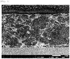
- FIG. 1 shows one example of a cross-sectional image of an electrode using a negative electrode material of one embodiment in the present invention.
- the negative electrode material for a lithium ion secondary battery of the present invention comprises a carbon-coated composite material.
- the carbon-coated composite material comprises a composite material, and additional amorphous carbon which the composite material is coated with.
- the composite material comprises silicon-containing particles, graphite particles and an amorphous carbon.
- the silicon-containing particles have the particle surface layer containing SiO x (0 ⁇ x ⁇ 2).
- a part (core) other than the surface layer may be composed of elemental silicon or may be composed of SiO x (0 ⁇ x ⁇ 2).
- An average thickness of the surface layer containing SiO x is preferably not less than 0.5 nm and not more than 10 nm. When the average thickness of the surface layer containing SiO x is not less than 0.5 nm, oxidation by air or oxidizing gas can be suppressed. When the average thickness of the surface layer containing SiO x is not more than 10 nm, increase in irreversible capacity at the initial cycle can be preferably suppressed. This average thickness can be measured by TEM photograph.
- the silicon-containing particles have a full width at half maximum of 111 diffraction peak derived from silicon, as observed in the X-ray diffraction with CuK ⁇ radiation, of preferably 0.3° to 0.5° as a scatter angle 2 ⁇ .
- the full width at half maximum is within the range, a balance between the cycle retention ratio and the initial charge/discharge efficiency is improved.
- the full width at half maximum of the 111 diffraction peak is preferably 0.3° or more, more preferably 0.4° or more, and further preferably 0.5° or more as the scatter angle 2 ⁇ .
- the full width at half maximum of the 111 diffraction peak is preferably 0.5° or less, more preferably 0.3° or less, and further preferably 0.2° or less as the scatter angle 2 ⁇ .
- the diffraction peak of silicon-containing particles can be measured using, for example, an X-ray diffraction apparatus SmartLab (registered trademark) manufactured by Rigaku Corporation or X-ray diffraction apparatus XRD-6100 manufactured by SHIMADZU CORPORATION.
- the full width at half maximum is determined by analyzing a diffraction peak obtained by measuring when the tube voltage is 45 kV, the tube current is 200 mA, the entrance slit and the exit slit in the concentration method are 10 mm, the speed coefficient of the one-dimensional detector is 2.0, and the angular resolution of the goniometer is 1.0 deg using a CuK ⁇ radiation.
- XRD analysis software such as, for example, PDXL2 manufactured by Rigaku Corporation can be used.
- the silicon-containing particles have a BET specific surface area of preferably not less than 50 m 2 /g and not more than 200 m 2 /g, and more preferably not less than 140 m 2 /g and not more than 200 m 2 /g.
- the BET specific surface area of silicon-containing particles is large because a particle diameter of the silicon-containing particles is small, an effect of relaxing volume strain accompanying intercalation of Li into a Si crystal phase is enhanced, and expansion and contraction accompanying charge and discharge can be further suppressed.
- the specific surface area is too large, handling property in production process tends to be deteriorated.
- the BET specific surface area is measured by a multipoint BET method with relative pressures of 0.1, 0.2 and 0.3 by applying nitrogen gas as a probe by using Surface Area & Pore Size Analyzer NOVA 4200e manufactured by Quantachrome Instruments, or NOVA-1200 manufactured by Yuasa Ionics Co., Ltd.
- the silicon-containing particles can comprise an element M selected from the other elements in addition to silicon in the particles.
- the element M can include nickel, copper, iron, tin, aluminum, cobalt, and the like. Two or more elements may be comprised as the element M.
- the content of the element M is not particularly limited as long as the effect of silicon is not largely inhibited, and the content is, for example, not more than 1 mole relative to 1 mole of silicon atom.
- the silicon-containing particles are not particularly limited by a production method thereof.
- the silicon-containing particles can be produced by, for example, a method disclosed in WO 2012/000858 A .
- An amount of the silicon-containing particles comprised in the composite material is preferably not less than 6 parts by mass and not more than 70 parts by mass, more preferably not less than 12 parts by mass and not more than 50 parts by mass, and further preferably not less than 15 parts by mass and not more than 40 parts by mass with respect to 100 parts by mass of the composite material. This range is preferable because balance between the volume change accompanying intercalation and deintercalation of lithium ions, and electric capacity is further improved.
- Graphite particles are preferably composed of artificial graphite. Furthermore, the graphite particles are preferably flake particles.
- the graphite particles have a 50% diameter D 50 in a volume-based cumulative particle size distribution of preferably 1 ⁇ m to 50 ⁇ m, more preferably 2 ⁇ m to 20 ⁇ m, and further preferably 3 ⁇ m to 10 ⁇ m. It is preferable that when D 50 of the graphite particles is 1 ⁇ m or more, a side reaction is hard to occur during charge and discharge, and when D 50 of the graphite particles is 50 ⁇ m or less, a diffusion speed of lithium ions in the negative electrode material tends to increase and a rate of charge and discharge tends to improve. In a case of an application to a driving power source for an automobile or the like which requires large current generation, D 50 is preferably 25 ⁇ m or less.
- D 50 is measured using a laser diffraction particle size analyzer, for example, Mastersizer (registered trademark) manufactured by Malvern Instruments Ltd.
- the graphite particles have d 002 of preferably 0.337 nm or less. As d 002 is smaller, the amount of intercalation and deintercalation of lithium ions per mass increases, which therefore contributes to an improvement in mass energy density. If d 002 is 0.337 nm or less, optical textures observed by a polarization microscope are almost optical anisotropic textures.
- the graphite particles have L c of preferably not less than 50 nm and not more than 1000 nm.
- L c is preferably not less than 80 nm and not more than 300 nm, and more preferably not less than 90 nm and not more than 250 nm.
- L c is preferably not less than 50 nm and not more than 250 nm. L c is calculated by analysis of X-ray diffraction pattern of CuK ⁇ radiation.
- d 002 and L c can be measured by a powder X-ray diffraction method. Details thereof are described in 117th Committee material 117-71-A-1(1963) Japan Society for the Promotion of Science , 117th Committee material 117-121-C-5 (1972) Japan Society for the Promotion of Science , and " Carbon” 1963, No.36, p.25-34 , etc.
- d 002 and L c of graphite particles can be calculated based on diffraction peaks of the carbon-coated composite material.
- the diffraction peaks of the carbon-coated composite material can be measured using, for example, an X-ray diffraction apparatus such as SmartLab (registered trademark) manufactured by Rigaku Corporation or an X-ray diffraction apparatus XRD-6100 manufactured by SHIMADZU CORPORATION.
- X-ray diffraction apparatus such as SmartLab (registered trademark) manufactured by Rigaku Corporation or an X-ray diffraction apparatus XRD-6100 manufactured by SHIMADZU CORPORATION.
- X-ray diffraction apparatus such as SmartLab (registered trademark) manufactured by Rigaku Corporation
- XRD-6100 manufactured by SHIMADZU CORPORATION.
- CuK ⁇ radiation is used, a tube voltage is 45 kV, a tube current is 200 mA, the entrance slit and the exit s
- the measured diffraction peak can be analyzed using XRD analysis software such as, for example, PDXL2 manufactured by Rigaku Corporation. Removal of background and smoothing are carried out, then, a peak of amorphous carbon is removed using software having a peak fitting function such as Origin (registered trade mark) manufactured by LightStone Corp., and d 002 and L c of graphite particles can be calculated.
- XRD analysis software such as, for example, PDXL2 manufactured by Rigaku Corporation. Removal of background and smoothing are carried out, then, a peak of amorphous carbon is removed using software having a peak fitting function such as Origin (registered trade mark) manufactured by LightStone Corp., and d 002 and L c of graphite particles can be calculated.
- graphite particles may be subjected to high heat.
- the maximum temperature at that time is not more than 2000 °C. Even if graphite particles are exposed to this level of heat, the crystal structure of the graphite particles is not changed. Therefore, d 002 and L c of graphite particles in the carbon-coated composite material are not changed as those of the raw material.
- the graphite particle has a BET specific surface area of preferably not less than 0.4 m 2 /g and not more than 25 m 2 /g, further preferably not less than 0.5 m 2 /g and not more than 20 m 2 /g, still further preferably not less than 0.5 m 2 /g and not more than 18 m 2 /g.
- the graphite has a BET specific surface area falling within the above-mentioned range, because excessive binders are not used, a large area in contact with an electrolytic solution can be secured, a lithium ion can be smoothly intercalated and deintercalated, and reaction resistance of a battery can be made smaller.
- the BET specific surface area is measured by a multipoint BET method using nitrogen gas as a probe under a relative pressure of 0.1, 0.2 and 0.3.
- Examples of the device for measuring the BET specific surface area can include Surface Area & Pore Size Analyzer NOVA 4200e manufactured by Quantachrome Instruments Ltd, or NOVA-1200 manufactured by Yuasa Ionics Co., Ltd.
- the graphite particles have a loose bulk density (tapped 0 times) of preferably not less than 0.1 g/cm 3 , and a powder density (tap density) upon being tapped 400 times of preferably not less than 0.1 g/cm 3 and not more than 1.6 g/cm 3 , more preferably not less than 0.15 g/cm 3 and not more than 1.6 g/cm 3 , and further preferably not less than 0.2 g/cm 3 and not more than 1.6 g/cm 3 .
- the loose bulk density is a density obtained by dropping 100 g of a sample into a measuring cylinder from a height of 20 cm and measuring a volume and mass without applying vibration.
- the tap density is a density obtained by measuring a volume and mass of 100 g of powder tapped 400 times by using Autotap manufactured by Quantachrome Instruments. These measurement methods comply with ASTM B527 or JIS K5101-12-2. A drop height in the Autotap in the tap density measurement is adjusted to 5 mm.
- the loose bulk density is preferably not less than 0.7 g/cm 3 , because the electrode density before being pressed tends to be increased upon coating the powder onto the electrode. Whether or not sufficient electrode density can be obtained by pressing one time can be predicted by the value. Moreover, it is preferable that the electrode density to be reached during pressing is easily adjusted to a desired level by keeping the tap density within the range described above.
- the artificial graphite particles can be obtained by graphitizing carbon precursor.
- a method disclosed in WO 2014/003135 A can be employed.
- coal coke and/or petroleum coke can be used as a raw material (carbon precursor) of the graphite particles.
- the graphite particles are produced by subjecting the coal coke and/or the petroleum coke to a heat treatment at a temperature of preferably not less than 2000 °C, and more preferably not less than 2500 °C.
- An upper limit of the temperature of the heat treatment is not particularly limited, but 3200 °C is preferable.
- the heat treatment described above is preferably conducted under an inert atmosphere.
- the heat treatment can be conducted by using, for example, an Acheson type graphitization furnace.
- the amount of graphite particles comprised in the composite material is preferably 5 to 90 parts by mass, and more preferably 10 to 80 parts by mass with respect to 100 parts by mass of the composite material. Note here that it can be considered that the mass of graphite particles is not changed before and after the producing step of the composite material.
- amorphous carbon means nongraphitized carbon.
- amorphous carbon can be produced by carbonizing a carbon precursor.
- the carbon precursor is not particularly limited, but is preferably hot heavy oil, thermally cracked oil, straight asphalt, blown asphalt, a material derived from petroleum such as tar or petroleum pitch by-produced during ethylene production, coal tar produced during coal dry-distillation, a heavy component obtained by distilling coal tar to remove a low-boiling component, a material derived from coal such as coal tar pitch, and the like, and is particularly preferably petroleum pitch or coal pitch.
- the pitch is a mixture of a plurality of polycyclic aromatic compounds. Use of the pitch can produce amorphous carbon having little impurities with a high carbonization ratio.
- the pitch has a small oxygen content, and therefore the silicon-containing particles are hard to be oxidized in carbonization.
- the pitch has a softening point of preferably not less than 80 °C and not more than 300 °C.
- the pitch having an excessively low softening point has a small average molecular weight of the polycyclic aromatic compound constituting the pitch and a high content of volatile matters, and therefore the carbonization ratio is lowered, production cost increases, or further the amorphous carbon having a large amount of fine pores and a large specific surface area is easily obtained.
- the pitch having an excessively high softening point has a high viscosity, and therefore it tends to be hardly mixed with the silicon-containing particles uniformly.
- the softening point of the pitch can be measured by a Mettler Method described in ASTM D3104-77.
- the pitch has a residual carbon ratio of preferably not less than 20% by mass and not more than 70% by mass, and more preferably not less than 25% by mass and not more than 60% by mass. If the pitch having a low residual carbon ratio is used, the production cost increases, and the amorphous carbon having a large specific surface area is easily obtained.
- the pitch having a high residual carbon ratio generally has high viscosity, and therefore it tends to be hardly mixed with the silicon-containing particles uniformly.
- the residual carbon ratio is determined by a method described below. Solid pitch is pulverized with a mortar or the like, and the pulverized pitch is subjected to thermogravimetric analysis under flow of nitrogen gas. A proportion of mass at 1100 °C to charged mass is defined as the residual carbon ratio. The residual carbon ratio corresponds to a fixed carbon content as measured at a carbonization temperature of 1100 °C in JIS K2425.
- the pitch has a quinolone-insoluble (QI) content of preferably not more than 10% by mass, more preferably not more than 5% by mass, and further preferably not more than 2% by mass.
- QI content of the pitch is a value corresponding to an amount of free carbon. If the pitch containing a large amount of free carbon is subjected to heat treatment, in a process where a mesophase sphere appears, the free carbon adheres onto a surface of the mesophase sphere to form a three-dimensional network, which inhibits growth of the sphere, and therefore a mosaic texture is easily formed. On the other hand, if the pitch having a small amount of free carbon is subjected to heat treatment, the mesophase sphere significantly grows to easily produce needle coke. The battery characteristics become further favorable by keeping the QI content within the range described above.
- the pitch has a toluene-insoluble (TI) content of preferably not less than 10% by mass and not more than 70% by mass.
- the pitch having a low TI content has a small average molecular weight of the polycyclic aromatic compound constituting the pitch, and a high content of volatile matters, and therefore a carbonization ratio is lowered and the production cost increases, and therefore the amorphous carbon having a large amount of fine pores and having a large specific surface area is easily obtained.
- the pitch having a high TI content has a large average molecular weight of the polycyclic aromatic compounds constituting the pitch, and therefore the carbonization ratio increases.
- the pitch having the high TI content has high viscosity, and therefore it tends to be hardly mixed with the silicon-containing particles uniformly.
- the pitch and other components can be uniformly mixed by keeping the TI content within the range described above, and the composite material having preferable characteristics as a material for the negative electrode can be obtained.
- the QI content and the TI content of the pitch can be measured according to a method described in JIS K2425 or a method based thereon.
- An amount of the amorphous carbon comprised in the composite material has the upper limit of preferably 4 parts by mass, more preferably 6 parts by mass, and further preferably 8 parts by mass, and the lower limit of preferably 50 parts by mass, and more preferably 40 parts by mass, with respect to 100 parts by mass of the composite material.
- the amounts of the graphite particles and the amorphous carbon comprised in the carbon-coated composite material can be calculated by carrying out thermogravimetric / differential thermal analysis under air atmosphere.
- the mass of the amorphous carbon comprised in the composite material can be calculated as a mass in terms of residual carbon of a carbon precursor used as a raw material.
- the "in terms of residual carbon” means that an amount of carbon precursor is converted to an amount remaining after carbonization of the carbon precursor.
- the amount of the carbon precursor in terms of residual carbon is calculated based on the amount of the carbonaceous precursor and the residual carbon ratio.
- a mass in terms of residual carbon is a value obtained by dividing a product of the mass of the carbonaceous material precursor and residual carbon ratio [% by mass] of the carbonaceous material precursor by 100.
- Additional amorphous carbon which the composite material is coated with may have the same physical properties as mentioned above as those of the amorphous carbon comprised in the composite material, or may have the different physical properties as mentioned above from those of the amorphous carbon comprised in the composite material.
- the additional amorphous carbon is obtained by carbonizing the carbon precursor as in the amorphous carbon comprised in the composite material.
- the lower limit of the mass of the additional amorphous carbon is preferably 0.6/99.4, more preferably 0.8/99.2, and further preferably 1.0/99.0 with respect to the mass of the composite material.
- the upper limit of the mass of the additional amorphous carbon is preferably 20/80, more preferably 10/90, and further preferably 5/95 with respect to the mass of the composite material.
- the carbon-coated composite material has a ratio D/(A+B+C) of a square measure (D) of a peak in the region of 99 to 105 eV to a total of a square measure (A) of a peak in the region of 396 to 400 eV, a square measure (B) of a peak in the region of 283 to 288 eV and a square measure (C) of a peak in the region of 530 to 536 eV of preferably not more than 0.015, more preferably not more than 0.014, particularly preferably not more than 0.013, and most preferably not more than 0.008, as observed by X-ray photoelectron spectroscopy (XPS).
- XPS X-ray photoelectron spectroscopy
- the reductive decomposition reaction of an electrolytic solution on the surface of the active material tends to be suppressed.
- the peak A is derived from nitrogen.
- the peak B is derived from carbon.
- the peak C is derived from oxygen.
- the peak D is derived from silicon.
- the X-ray photoelectron spectroscopy can be carried out using, for example, X-ray Photoelectron Spectrometry (Quantera II) manufactured by ULVAC-PHI, Inc.
- the square measure (A), square measure (B), square measure (C) and square measure (D) can be measured under the following conditions.
- the carbon-coated composite material has a surface roughness S/T of preferably not more than 7.3, more preferably not more than 7, further preferably not more than 6.5, and particularly preferably not more than 6.
- S/T surface roughness
- the surface roughness S/T is ratio S/T of the BET specific surface area S to the specific surface area T of sphere approximation calculated based on the volume-based cumulative particle size distribution measured by the laser diffraction method.
- the specific surface area T of the sphere approximation is determined as follows.
- Measurement method Two micro spatulas of measurement sample and two droplets of a non-ionic surfactant (TRITON (registered trademark)-X manufactured by Roche Applied Science) are added to 50 mL of water, and the resultant mixture is subjected to ultrasonic dispersion for three minutes. The obtained dispersion liquid is charged into a laser diffraction particle size distribution measurement instrument to measure a volume-based cumulative particle size distribution.
- TRITON registered trademark
- X manufactured by Roche Applied Science
- the true density can be measured by gas phase replacement method.
- the gas phase replacement method is a method to calculate the true density from the volume of helium gas in a predefined volume in an environment maintained at a constant temperature.
- As an apparatus for the gas phase replacement method for example, Ultrapyc 1200e manufactured by QuantaChrome can be used.
- the carbon-coated composite material has the upper limit of the BET specific surface area of preferably 3 m 2 /g, more preferably 2 m 2 /g, and further preferably 1.5 m 2 /g, and the lower limit of the BET specific surface area of preferably 0.85 m 2 /g, and more preferably 0.95 m 2 /g.
- the BET specific surface area is larger, the contact area with the electrolytic solution is larger, the reductive decomposition of the electrolytic solution is more promoted, and the charge and discharge efficiency tends to be deteriorated. Meanwhile, when the BET specific surface area is smaller, diffusion speed of the lithium ion decreases, causing lowering the charge and discharge velocity.
- the carbon-coated composite material has 10% diameter D 10 in the volume-based cumulative particle size distribution as measured by a laser diffraction method of preferably not less than 1 ⁇ m, more preferably not less than 2 ⁇ m, and further preferably not less than 2.5 ⁇ m. If D 10 is excessively small, binding force between the negative electrode material and a current collector is likely to decrease to cause a problem in which the negative electrode material is peeled off upon charge and discharge. An upper limit of D 10 can be appropriately set based on a relationship with a thickness of the electrode.
- the carbon-coated composite material has I D/ I G in Raman spectrum (this ratio may also be referred to as "R value") of preferably 0.2 to 4, more preferably 0.4 to 3, and further preferably 0.7 to 2.
- R value is not less than 0.2
- Si is sufficiently coated with amorphous carbon, so that the cycle characteristics tend to be improved.
- the R value is not more than 4, the energy density tends to be improved.
- the carbon-coated composite material has I Si /I D in the Raman spectrum of preferably 0.01 to 1.2, and more preferably 0.04 to 0.5.
- I Si /I D of the composite material is made to be smaller, Si is sufficiently coated with amorphous carbon, and the cycle characteristics tend to be improved.
- the carbon-coated composite material has (I Si /I D )/(I D /I G ) in the Raman spectrum of preferably 0.05 to 0.3, and more preferably 0.05 to 0.25.
- this value is higher than 0.3, exposed Si is increased, so that cycle resistance may be reduced.
- this value is smaller than 0.05, the amount of Si is too small, so that the electric capacity may be smaller.
- I D is a peak intensity of the D-band (near 1350 cm -1 )
- I G is a peak intensity of the G-band (near 1580 cm -1 )
- I Si is a peak intensity of Si.
- I D/ I G and I Si /I D in Raman spectrum of the carbon-coated composite material are calculated by mapping measurement of the Raman spectrum of the composite material, determining the peak intensity (I DL ) of the D-band (near 1350 cm -1 ), the peak intensity (I GL ) of the G-band (near 1580 cm -1 ), and a peak intensity (I SIL ) of Si at each measurement point, and arithmetically averaging I DL /I GL and I SiL/ I DL at each measurement point.
- the measurement of the Raman spectrum is made to be shallow.
- the magnification of the objective lens of Raman microscopy is increased, and a laser spot diameter is reduced.
- Conditions for mapping measurement are as follow.
- the Raman spectrum of the carbon-coated composite material is divided into absorption derived from Si near 520 cm -1 , and absorption derived from carbon material in the region of 900 to 1900 cm -1 .
- the Raman spectrum of the carbon material is a composite band in which some peaks derived from structures of the carbon materials overlap to each other. Since structures of the carbon materials can be understood by the peak intensity ratio, they are divided into each peak. This method is referred to as a peak fitting method.
- peak fitting method well-known methods can be appropriately selected and used. Usually, a software for Raman microscopy analysis may be used. For example, Spectra Manager (registered trademark) manufactured by JASCO Corporation can be used. Analysis range of the peak fitting is 300 to 1900 cm -1 .
- the peak fitting of the carbon material is carried out by separating into the following each band.
- the spectrum is divided into six peaks including the above-mentioned five peaks of the carbon material and one peak derived from Si near 520 cm -1 .
- the D2-band is separated by peak fitting to calculate the peak intensity (I G ) of the G-band.
- NRS-5100 manufactured by JASCO Corporation can be used. Measurement conditions are as follows.
- silicon-containing particles coated with amorphous carbon are coupled to the outer periphery of the graphite particles.
- silicon-containing particles coated with amorphous carbon are not present inside the graphite particles.
- silicon-containing particles, graphite particles and amorphous carbon adhere to each other with no space therebetween (see Fig. 1 ).
- the embodiment improves conductivity between the graphite particles and the silicon-containing particles, and buffers the volume change accompanying expansion and contraction.
- silicon-containing particles, graphite particles and amorphous carbon are contained, and at least a part of the amorphous carbon is located between at least two silicon-containing particles and at least one graphite particle and links them both to each other to form a composite material, and further the composite material is coated with a remaining part of the amorphous carbon (additional amorphous carbon).
- additional amorphous carbon it is preferable that in a layer of the amorphous carbon in the composite material, for example, one graphite particle and a plurality of silicon-containing particles are dispersed and enclosed, and in a layer of the amorphous carbon with which the composite material is coated, neither graphite particles nor silicon-containing particles have existence.
- a method for producing a carbon-coated composite material is not particularly limited as long as the method enables a carbon-coated composite material having the physical properties and characteristics to be obtained.
- the method for producing a carbon-coated composite material of the preferable embodiment comprises subjecting a mixture I comprising silicon-containing particles, carbon precursor and graphite particles at a predetermined ratio to heat treatment for carbonization to obtain a composite material comprising the silicon-containing particles, the amorphous carbon and the graphite particles; mixing the obtained composite material and an additional carbon precursor with each other at a predetermined ratio to obtain a mixture II; and subjecting the obtained mixture II to heat treatment for carbonization.
- the carbon precursor mentioned can be carbon precursors described as those usable for producing composite materials. Among them, pitch is preferable.
- the amounts of the silicon-containing particles, the carbon precursor and the graphite particles in the mixture I are respectively set at the amounts of the silicon-containing particles, the amorphous carbon and the graphite particles comprised in composite material as mentioned above after heat treatment of the raw material compound.
- the residual carbon ratio is a ratio of the amorphous carbon generated at the heat treatment of a carbon precursor to the carbon precursor.
- the amount of the carbon precursor in the mixture I can be set such that the desired amount of the amorphous carbon is generated. Specifically, the amount of the carbon precursor can be calculated by dividing the desired amount of the amorphous carbon by the residual carbon ratio of the carbon precursor.
- the mixture I comprises preferably 6 to 70 parts by mass, more preferably 12 to 50 parts by mass and further preferably 15 to 40 parts by mass of silicon-containing particles, preferably 5 to 90 parts by mass and more preferably 10 to 80 parts by mass of graphite particles, and preferably not less than 4 parts by mass, more preferably not less than 6 parts by mass and further preferably not less than 8 parts by mass and preferably not more than 50 parts by mass and more preferably not more than 40 parts by mass of carbon precursor in terms of residual carbon, to 100 parts by mass of the total amount of the silicon-containing particles, pitch in terms of residual carbon and graphite particles.
- the mixture I can be obtained, for example, by melting pitch being one of carbon precursors, mixing the molten pitch and the silicon-containing particles under an inert atmosphere, pulverizing the resultant mixture, and mixing the resultant pulverized material with the graphite particles.
- the mixture I can be obtained, for example, by dissolving the carbon precursor by an appropriate method to obtain a liquid phase, mixing the silicon-containing particles and the graphite particles in the resultant liquid phase, and then pulverizing the resultant material.
- the mixture I can be obtained, for example, by mixing the silicon-containing particles and the graphite particles, mixing the resultant mixture with the carbon precursor, and then subjecting the mixture to mechanochemical processing.
- mechanochemical processing a well-known device such as Hybridizer (registered trademark) manufactured by Nara Machinery Co., Ltd. or the like can be employed.
- a well-known device such as a ball mill, a jet mill, a rod mill, a pin mill, a rotary cutter mill, a hammer mill, an atomizer, a mortar or the like can be used.
- the pulverizing or mixing method according to which an oxidization degree of the silicon-containing particles is not increased is preferably applied. Oxidization is generally considered to further progress in smaller sized particles having a larger specific surface area, and therefore a device is preferably used in which pulverizing of large sized particles preferentially progresses, and pulverizing of small sized-particles does not significantly progress.
- a means for pulverizing mainly by impact such as the rod mill and the hammer mill
- impact power tends to be preferentially transmitted to the large sized particles and not significantly transmitted to the small sized particles.
- a means for pulverizing mainly by impact and shear such as the pin mill and rotary cutter mill
- the shearing force tends to be preferentially transmitted to the large sized particles and not significantly transmitted to the small sized particles.
- pulverizing and mixing are carried out, without causing progress of oxidization of the silicon containing particles, using the device.
- the pulverizing and mixing are conducted preferably under a non-oxidizing atmosphere in order to suppress progress of oxidization of silicon-containing particles.
- the non-oxidizing atmosphere can include an atmosphere in which inert gas such as argon gas, nitrogen gas, or the like, is filled.
- a temperature during heat treatment of mixture I is not less than 200 °C and not more than 2000 °C, more preferably not less than 300 °C and not more than 1000 °C, and further preferably not less than 400 °C and not more than 800 °C.
- the heat treatment results in coating the silicon-containing particles or the graphite particles with the amorphous carbon, and introducing the amorphous carbon into spaces between the silicon-containing particles, between the graphite particles, and between the silicon-containing particles and the graphite particles, to link therewith. If the heat treatment temperature is excessively low, carbonization of the carbon precursor may not be sufficiently terminated and hydrogen or oxygen remains in the composite material to adversely affect battery characteristics in several cases.
- the heat treatment of the mixture I is preferably conducted under the non-oxidizing atmosphere.
- the non-oxidizing atmosphere can include an atmosphere in which inert gas such as argon gas or nitrogen gas is filled.
- the particles may form into lump by fusion during the heat treatment of the mixture I, and therefore the lump is preferably disintegrated in order to use the heat-treated product as an electrode active material.
- a pulverizer using impact force of a hammer or the like or a jet mill using collision of the integrated material with each other or the like is preferred.
- the composite material obtained by heat treatment of the mixture I, and an additional carbon precursor are mixed with each other to obtain a mixture II.
- the amount of the additional carbon precursor is preferably set to an amount of the additional amorphous carbon with which the composite material is coated by heat treatment of the mixture II as mentioned above.
- the residual carbon ratio is a ratio of the amorphous carbon generated at the heat treatment of a carbon precursor to the carbon precursor. Based on the residual carbon ratio of the carbon precursor, the amount of the additional carbon precursor in the mixture II can be set such that the desired amount of the amorphous carbon is generated. Specifically, the amount of the additional carbon precursor can be calculated by dividing the desired amount of the amorphous carbon to be coated by the residual carbon ratio of the carbon precursor.
- the ratio of the mass of the composite material to be mixed herein and the mass of the additional carbon precursor in terms of residual carbon has a lower limit of 80:20, preferably 90:10, and more preferably 95:5, and an upper limit of 99.4:0.6, preferably 99.2:0.8, and more preferably 99.0:1.0.
- the composite material and the additional carbon precursor (pitch) are preferably mixed with each other by the method in which a shearing force or a compression force does not easily apply.
- this mixing method for example, a planetary centrifugal mixer, V-type mixing machine, and W-type mixing machine can be used.
- a planetary centrifugal mixer ARE-310 manufactured by THINKY CORPORATION 25 g of powder are preferably mixed at not less than 1000 rpm and not more than 1500 rpm for not less than 5 minutes.
- the mixing is preferably carried out repeatedly while manually stirring and defoaming are carried out.
- Mixing is preferably carried out in a non-oxidizing atmosphere in order to suppress progress of oxidation of silicon-containing particles.
- the non-oxidizing atmosphere can include an atmosphere filled with inert gas such as argon gas or nitrogen gas.
- a temperature at heat treatment of the mixture II has the lower limit of 200 °C, preferably 900 °C, and more preferably 1000 °C, and the upper limit of 2000 °C, preferably 1500 °C, and more preferably 1200 °C.
- Heat treatment of the mixture II allows amorphous carbon with which the composite material is coated to be generated.
- a plurality of coatings with amorphous carbon may be carried out by mixing the generated product with another carbon precursor and subjecting the generated product to heat treatment.
- the negative electrode material of the present invention may be composed of only a carbon-coated composite material, or may be composed of a carbon-coated composite material, additional graphite particles, another amorphous carbon and/or additional silicon-containing particles.
- the additional graphite particles may be natural graphite or artificial graphite.
- the additional graphite particles have a 50% diameter D 50 with the volume-based cumulative particle size distribution of preferably 1 ⁇ m to 50 ⁇ m, d 002 of preferably not more than 0.337 nm, L c of preferably not less than 50 nm and not more than 1000 nm, and BET specific surface area of preferably not less than 0.4 m 2 /g and not more than 25 m 2 /g.
- the mass ratio of the carbon-coated composite material to the additional graphite particles can be appropriately set for a desired electric capacity value.
- additional silicon-containing particles mentioned can be the same as those described in the silicon-containing particles to be used for production of the composite material.
- the mass ratio of the additional silicon-containing particles to the carbon-coated composite material can be appropriately set for a desired electric capacity value.
- Examples of the other amorphous carbon can include carbon black, Ketjen black, and the like.
- the mass ratio of the other amorphous carbon to the carbon-coated composite material can be appropriately set for a desired electric capacity value.
- a negative electrode material can be produced by adding fibrous carbon to the carbon-coated composite material.
- fibrous carbon can include carbon nanotube, carbon nanofiber, and the like.
- the mass ratio of the fibrous carbon to the carbon-coated composite material can be appropriately set for a desired electric capacity value.
- a carbon-coated composite material (d) was obtained in the same manner as in Example 2 except that repeating of mixing at 1000 rpm for 5 minutes using a planetary centrifugal mixer and mixing by manual stirring for 2 minutes twice was changed to mixing at 1000 rpm for 3 minutes and mixing at 6000 rpm for 10 minutes using an MP mixer manufactured by NIPPON COKE & ENGINEERING CO., LTD.
- a carbon-coated composite material (e) was obtained in the same manner as in Example 2 except that 1 part by mass of petroleum pitch was added to 99 parts by mass of composite material (a) (the ratio of the mass of composite material (a) to the mass of petroleum pitch in terms of residual carbon was 99.5:0.5) instead of adding 2 parts by mass of petroleum pitch to 98 parts by mass of composite material (a).
- the composite material (a) was placed in a firing furnace, temperature was increased to 1050 °C at 150 °C/h and held at 1050 °C for one hour under flow of nitrogen gas.
- the fired product was cooled to room temperature, removed from the firing furnace, disintegrated, and classified by a sieve having an opening of 45 ⁇ m to obtain a composite material (g) as an undersize product.
- the negative electrode piece was dried in vacuum at 80 °C for 12 hours, soaked in the electrolytic solution, and subjected to vacuum impregnation at -0.95 atm for 10 minutes.
- the negative electrode piece impregnated with an electrolytic solution was placed at the positive electrode side of a 2320-type coin cell, a separator impregnated with an electrolytic solution was put thereon. Further, 1.7 mm thick metallic lithium punched into 20 mm ⁇ was put thereon, and the negative electrode side of the coin cell was placed as a lid, and caulked by a calking machine to obtain a half cell.
- this half cell was subjected to constant current charge at 0.1 C. From a time point when voltage reached 10 mV, constant voltage charge was carried out. Charge was stopped at a time point when current reached 0.01C. Next, constant current discharge was carried out at 0.1C. At a time point when the voltage reached 1.5 V, discharge was stopped. Discharge capacity was calculated by dividing discharge electric amount by a mass of the active material.
- Composite material and artificial graphite particles were mixed with each other so that the discharge capacity was 600 mAh/g to obtain a mixture.
- Ninety parts by mass of the mixture 1.2 parts by mass of carbon black (manufactured by TIMCAL), 0.4 part by mass of vapor grown carbon fiber (VGCF (registered trademark)-H, manufactured by Showa Denko K.K.), 0.4 part by mass of carbon nanotube (fiber diameter: 15 nm), and an aqueous solution containing 8 parts by mass of CMC were mixed with each other, and kneaded by a planetary centrifugal mixer to obtain paste for a negative electrode.
- the paste for a negative electrode was uniformly applied on a 20 ⁇ m thick copper foil using a doctor blade while the thickness was adjusted so that the ratio QC/QA of the capacity (QA) of the negative electrode sheet to the capacity (QC) of the positive electrode sheet was 1.2, dried on a hot plate, and then dried in vacuum.
- the resultant product was pressed by roll press machine to obtain a negative electrode sheet having an electrode density of 1.6 g/cm 3 .
- the negative electrode sheet and the positive electrode sheet were punched, respectively, to obtain a negative electrode piece and a positive electrode piece each having a square measure of 20 cm 2 .
- An aluminum tab was attached to the aluminum foil in the positive electrode piece, and a nickel tab was attached to the copper foil in the negative electrode piece, respectively.
- a microporous film made of polypropylene was interposed between the negative electrode piece and the positive electrode piece, and the resultant material in the sandwiched state was packed in an aluminum laminate. Then, the electrolytic solution was poured thereinto, and an opening portion was sealed to obtain a full cell.
- the full cell was subjected to pre-stage charge and discharge in a manner as shown in Table 1. After the pre-stage charge and discharge were carried out, charge and discharge were repeated in 481 cycles in a manner shown in Table 2. A value was obtained by dividing the discharge capacity of the 450th cycle by the discharge capacity of the first cycle, and the value was defined as a discharge amount retention ratio.
- Table 3 Compo. material XPS D/ (A+B+C) Surface roughness S/T Raman I D/ I G Raman I Si /I D Raman (I Si / I D ) / (I D / I G ) BET S.S.A (S) [m 2 /g] Sphere approx.
Landscapes
- Chemical & Material Sciences (AREA)
- Organic Chemistry (AREA)
- Chemical Kinetics & Catalysis (AREA)
- Electrochemistry (AREA)
- General Chemical & Material Sciences (AREA)
- Inorganic Chemistry (AREA)
- Composite Materials (AREA)
- Life Sciences & Earth Sciences (AREA)
- General Life Sciences & Earth Sciences (AREA)
- Geology (AREA)
- Engineering & Computer Science (AREA)
- Manufacturing & Machinery (AREA)
- Battery Electrode And Active Subsutance (AREA)
Abstract
Description
- The present invention relates to a negative electrode material for a lithium ion secondary battery and uses thereof. More particularly, the present invention relates to a negative electrode material from which a lithium ion secondary battery having excellent charge/discharge cycle characteristics can be obtained, an electrode comprising the negative electrode material, and a lithium ion secondary battery comprising the negative electrode material.
- Graphite is generally used as a negative electrode material for a lithium ion secondary battery. Theoretical capacity of graphite is 372 mAh/g. Theoretical capacity of Si or Sn is higher than that of graphite, and therefore, if Si or Sn can be used as the negative electrode material, a lithium ion secondary battery having high capacity can be provided. However, particles containing Si or Sn have low electric conductivity. Further, volume change associated with intercalation and deintercalation of lithium ion is large, so that charge/discharge efficiency is rapidly deteriorated. Various materials to solve the problems have been proposed.
- For example, Patent Document 1 discloses a negative electrode material for a lithium secondary battery, composed of silicon particles and a carbon precursor, in which a covering layer composed of a non-graphitic carbon material is formed on a surface of the silicon particles, and a peak intensity ratio of silicon to carbon in X-ray photoelectron spectroscopy analysis is 0 to 0.2.
- Patent Document 2 discloses a negative electrode material for a lithium ion secondary battery, comprising silicon particles and a layer composed of carbon on a surface of the silicon particles, wherein the particles have average particle size of 5 nm or more and 100 nm or less, and a square measure of a peak in the vicinity of 104 eV derived from silicon oxide is smaller than 25% of a sum of square measures of peaks in the vicinity of 100 eV derived from silicon and silicon-carbon in X-ray photoelectron spectroscopy analysis.
- Patent Document 3 discloses a negative electrode material for a lithium secondary battery, comprising Si particles having an average particle diameter (D50) of 0.05 to 5 µm and several types of carbonaceous materials, and having an oxygen content of 5% by weight or less.
- Patent Document 4 discloses a composite electrode material comprising graphite particles, amorphous carbon, and silicon, having the silicon content in terms of SiO2 of 40 to 80% by weight, the true density of 1.8 × 10³ kg/m3 or more, the tap density of 0.8 × 10³ kg/m3 or more, and the specific surface area of 8 × 10³ m2/kg or less, and having one peak in the region of 102.5 to 107.5 eV in Si2P spectrum in XPS.
-
- Patent Document 1 :
JP 2004-259475 A - Patent Document 2 :
WO 2014/007161 A - Patent Document 3 :
JP 2008-112710 A - Patent Document 4 :
JP 2002-231225 A - An object of the present invention is to provide a negative electrode material for a lithium ion secondary battery, from which a lithium ion secondary battery having large discharge capacity and excellent charge/discharge cycle characteristics can be obtained.
- The present invention includes the following embodiments.
- [1] A negative electrode material for a lithium ion secondary battery, comprising a carbon-coated composite material comprising a composite material comprising silicon-containing particles, graphite particles and an amorphous carbon, and an additional amorphous carbon with which the composite material is coated, wherein the carbon-coated composite material has a ratio D/(A+B+C) of a square measure (D) of a peak in the region of 99 to 105 eV to a total of a square measure (A) of a peak in the region of 396 to 400 eV, a square measure (B) of a peak in the region of 283 to 288 eV, and a square measure (C) of a peak in the region of 530 to 536 eV, of not more than 0.015, as observed by X-ray photoelectron spectroscopy (XPS), and a ratio S/T of a BET specific surface area S to a specific surface area T of sphere approximation calculated based on a volume-based cumulative particle size distribution measured by a laser diffraction method, of not more than 7.3.
- [2] The negative electrode material for a lithium ion secondary battery according to the embodiment [1], wherein the carbon-coated composite material has: ID/IG of 0.2 to 4, ISi/ID of 0.01 to 1.2, and (ISi/ID)/(ID/IG) of 0.05 to 0.3, as determined by Raman spectroscopy.
- [3] The negative electrode material for a lithium ion secondary battery according to the embodiment [1] or [2], wherein the graphite particles have: d002 of not more than 0.337 nm, and Lc of 50 nm to 1000 nm.
- [4] The negative electrode material for a lithium ion secondary battery according to any one of the embodiments [1] to [3], wherein the silicon-containing particles, the graphite particles and the amorphous carbon adhere to each other with no space therebetween in the carbon-coated composite material.
- [5] The negative electrode material for a lithium ion secondary battery according to any one of the embodiments [1] to [4], further comprising additional graphite particles.
- [6] A slurry or a paste, comprising the negative electrode material for a lithium ion secondary battery according to any one of the embodiments [1] to [5], and a binder.
- [7] An electrode comprising the negative electrode material for a lithium ion secondary battery according to any one of the embodiments [1] to [5], and a binder.
- [8] A lithium ion secondary battery comprising the negative electrode material for a lithium ion secondary battery according to any one of the embodiments [1] to [5].
- [9] A method for producing a carbon-coated composite material, the method comprising:
- heat-treating a mixture I at not less than 200 °C and not more than 2000 °C to obtain a composite material comprising silicon-containing particles, an amorphous carbon and graphite particles, the mixture I comprising 6 to 70 parts by mass of the silicon-containing particles, 4 to 50 parts by mass of pitch in terms of residual carbon, 5 to 90 parts by mass of the graphite particles based on 100 parts by mass of a total of an amount of the silicon-containing particles, an amount of the pitch in terms of residual carbon and an amount of the graphite particles;
- mixing the obtained composite material and an additional pitch with each other such that a ratio of a mass of the obtained composite material to a mass of the additional pitch in terms of residual carbon is 80/20 to 99.4/0.6 to obtain a mixture II,
- and then
- heat-treating the obtained mixture II at not less than 200 °C and not more than 2000 °C.
- [10] The method according to the embodiment [9], wherein a temperature in the heat-treating of the mixture I is not less than 300 °C and not more than 1000 °C, and a temperature in the heat-treating of the mixture II is not less than 800 °C and not more than 1500 °C.
- The negative electrode material for a lithium ion secondary battery of the present invention can provide a lithium ion secondary battery having a large discharge capacity, and excellent charge/discharge cycle characteristics.
-
FIG. 1 shows one example of a cross-sectional image of an electrode using a negative electrode material of one embodiment in the present invention. - The negative electrode material for a lithium ion secondary battery of the present invention comprises a carbon-coated composite material.
- The carbon-coated composite material comprises a composite material, and additional amorphous carbon which the composite material is coated with.
- The composite material comprises silicon-containing particles, graphite particles and an amorphous carbon.
- Preferably, the silicon-containing particles have the particle surface layer containing SiOx (0<x≤2). A part (core) other than the surface layer may be composed of elemental silicon or may be composed of SiOx (0<x≤2). An average thickness of the surface layer containing SiOx is preferably not less than 0.5 nm and not more than 10 nm. When the average thickness of the surface layer containing SiOx is not less than 0.5 nm, oxidation by air or oxidizing gas can be suppressed. When the average thickness of the surface layer containing SiOx is not more than 10 nm, increase in irreversible capacity at the initial cycle can be preferably suppressed. This average thickness can be measured by TEM photograph.
- The silicon-containing particles have a full width at half maximum of 111 diffraction peak derived from silicon, as observed in the X-ray diffraction with CuKα radiation, of preferably 0.3° to 0.5° as a scatter angle 2θ. When the full width at half maximum is within the range, a balance between the cycle retention ratio and the initial charge/discharge efficiency is improved. Furthermore, when the cycle retention ratio is to be particularly improved in the lithium ion secondary battery, the full width at half maximum of the 111 diffraction peak is preferably 0.3° or more, more preferably 0.4° or more, and further preferably 0.5° or more as the scatter angle 2θ. When the initial charge/discharge efficiency is to be particularly improved in the lithium ion secondary battery, the full width at half maximum of the 111 diffraction peak is preferably 0.5° or less, more preferably 0.3° or less, and further preferably 0.2° or less as the scatter angle 2θ.
- The diffraction peak of silicon-containing particles can be measured using, for example, an X-ray diffraction apparatus SmartLab (registered trademark) manufactured by Rigaku Corporation or X-ray diffraction apparatus XRD-6100 manufactured by SHIMADZU CORPORATION.
- The full width at half maximum is determined by analyzing a diffraction peak obtained by measuring when the tube voltage is 45 kV, the tube current is 200 mA, the entrance slit and the exit slit in the concentration method are 10 mm, the speed coefficient of the one-dimensional detector is 2.0, and the angular resolution of the goniometer is 1.0 deg using a CuKα radiation. In the analysis, XRD analysis software such as, for example, PDXL2 manufactured by Rigaku Corporation can be used.
- The silicon-containing particles have a BET specific surface area of preferably not less than 50 m2/g and not more than 200 m2/g, and more preferably not less than 140 m2/g and not more than 200 m2/g.
- It is preferable that the BET specific surface area of silicon-containing particles is large because a particle diameter of the silicon-containing particles is small, an effect of relaxing volume strain accompanying intercalation of Li into a Si crystal phase is enhanced, and expansion and contraction accompanying charge and discharge can be further suppressed. However, when the specific surface area is too large, handling property in production process tends to be deteriorated.
- Note here that the BET specific surface area is measured by a multipoint BET method with relative pressures of 0.1, 0.2 and 0.3 by applying nitrogen gas as a probe by using Surface Area & Pore Size Analyzer NOVA 4200e manufactured by Quantachrome Instruments, or NOVA-1200 manufactured by Yuasa Ionics Co., Ltd.
- The silicon-containing particles can comprise an element M selected from the other elements in addition to silicon in the particles. Specific examples of the element M can include nickel, copper, iron, tin, aluminum, cobalt, and the like. Two or more elements may be comprised as the element M. The content of the element M is not particularly limited as long as the effect of silicon is not largely inhibited, and the content is, for example, not more than 1 mole relative to 1 mole of silicon atom.
- The silicon-containing particles are not particularly limited by a production method thereof. The silicon-containing particles can be produced by, for example, a method disclosed in
WO 2012/000858 A . - An amount of the silicon-containing particles comprised in the composite material is preferably not less than 6 parts by mass and not more than 70 parts by mass, more preferably not less than 12 parts by mass and not more than 50 parts by mass, and further preferably not less than 15 parts by mass and not more than 40 parts by mass with respect to 100 parts by mass of the composite material. This range is preferable because balance between the volume change accompanying intercalation and deintercalation of lithium ions, and electric capacity is further improved.
- Graphite particles are preferably composed of artificial graphite. Furthermore, the graphite particles are preferably flake particles. The graphite particles have a 50% diameter D50 in a volume-based cumulative particle size distribution of preferably 1 µm to 50 µm, more preferably 2 µm to 20 µm, and further preferably 3 µm to 10 µm. It is preferable that when D50 of the graphite particles is 1 µm or more, a side reaction is hard to occur during charge and discharge, and when D50 of the graphite particles is 50 µm or less, a diffusion speed of lithium ions in the negative electrode material tends to increase and a rate of charge and discharge tends to improve. In a case of an application to a driving power source for an automobile or the like which requires large current generation, D50 is preferably 25 µm or less.
- D50 is measured using a laser diffraction particle size analyzer, for example, Mastersizer (registered trademark) manufactured by Malvern Instruments Ltd.
- The graphite particles have d002 of preferably 0.337 nm or less. As d002 is smaller, the amount of intercalation and deintercalation of lithium ions per mass increases, which therefore contributes to an improvement in mass energy density. If d002 is 0.337 nm or less, optical textures observed by a polarization microscope are almost optical anisotropic textures.
- The graphite particles have Lc of preferably not less than 50 nm and not more than 1000 nm. When the energy density per volume is to be especially increased, Lc is preferably not less than 80 nm and not more than 300 nm, and more preferably not less than 90 nm and not more than 250 nm. When battery cycle characteristics are to be particularly improved, Lc is preferably not less than 50 nm and not more than 250 nm. Lc is calculated by analysis of X-ray diffraction pattern of CuKα radiation.
- d002 and Lc can be measured by a powder X-ray diffraction method. Details thereof are described in 117th Committee material 117-71-A-1(1963) Japan Society for the Promotion of Science, 117th Committee material 117-121-C-5 (1972) Japan Society for the Promotion of Science, and "Carbon" 1963, No.36, p.25-34, etc.
- d002 and Lc of graphite particles can be calculated based on diffraction peaks of the carbon-coated composite material. The diffraction peaks of the carbon-coated composite material can be measured using, for example, an X-ray diffraction apparatus such as SmartLab (registered trademark) manufactured by Rigaku Corporation or an X-ray diffraction apparatus XRD-6100 manufactured by SHIMADZU CORPORATION. In measurement, CuKα radiation is used, a tube voltage is 45 kV, a tube current is 200 mA, the entrance slit and the exit slit are 10 mm in the concentration method, the speed coefficient of the one-dimensional detector is 2.0, and the angular resolution of the goniometer is 1.0 deg. Then, the measured diffraction peak can be analyzed using XRD analysis software such as, for example, PDXL2 manufactured by Rigaku Corporation. Removal of background and smoothing are carried out, then, a peak of amorphous carbon is removed using software having a peak fitting function such as Origin (registered trade mark) manufactured by LightStone Corp., and d002 and Lc of graphite particles can be calculated.
- Note here that in production of carbon-coated composite materials, for obtaining amorphous carbon with which the composite material is coated, graphite particles may be subjected to high heat. The maximum temperature at that time is not more than 2000 °C. Even if graphite particles are exposed to this level of heat, the crystal structure of the graphite particles is not changed. Therefore, d002 and Lc of graphite particles in the carbon-coated composite material are not changed as those of the raw material.
- The graphite particle has a BET specific surface area of preferably not less than 0.4 m2/g and not more than 25 m2/g, further preferably not less than 0.5 m2/g and not more than 20 m2/g, still further preferably not less than 0.5 m2/g and not more than 18 m2/g.
- It is preferable that the graphite has a BET specific surface area falling within the above-mentioned range, because excessive binders are not used, a large area in contact with an electrolytic solution can be secured, a lithium ion can be smoothly intercalated and deintercalated, and reaction resistance of a battery can be made smaller. Note here that the BET specific surface area is measured by a multipoint BET method using nitrogen gas as a probe under a relative pressure of 0.1, 0.2 and 0.3.
- Examples of the device for measuring the BET specific surface area can include Surface Area & Pore Size Analyzer NOVA 4200e manufactured by Quantachrome Instruments Ltd, or NOVA-1200 manufactured by Yuasa Ionics Co., Ltd.
- The graphite particles have a loose bulk density (tapped 0 times) of preferably not less than 0.1 g/cm3, and a powder density (tap density) upon being tapped 400 times of preferably not less than 0.1 g/cm3 and not more than 1.6 g/cm3, more preferably not less than 0.15 g/cm3 and not more than 1.6 g/cm3, and further preferably not less than 0.2 g/cm3 and not more than 1.6 g/cm3.
- The loose bulk density is a density obtained by dropping 100 g of a sample into a measuring cylinder from a height of 20 cm and measuring a volume and mass without applying vibration. The tap density is a density obtained by measuring a volume and mass of 100 g of powder tapped 400 times by using Autotap manufactured by Quantachrome Instruments. These measurement methods comply with ASTM B527 or JIS K5101-12-2. A drop height in the Autotap in the tap density measurement is adjusted to 5 mm.
- The loose bulk density is preferably not less than 0.7 g/cm3, because the electrode density before being pressed tends to be increased upon coating the powder onto the electrode. Whether or not sufficient electrode density can be obtained by pressing one time can be predicted by the value. Moreover, it is preferable that the electrode density to be reached during pressing is easily adjusted to a desired level by keeping the tap density within the range described above.
- The artificial graphite particles can be obtained by graphitizing carbon precursor. As the production method of the artificial graphite particles, for example, a method disclosed in
WO 2014/003135 A can be employed. - As a raw material (carbon precursor) of the graphite particles, coal coke and/or petroleum coke can be used. The graphite particles are produced by subjecting the coal coke and/or the petroleum coke to a heat treatment at a temperature of preferably not less than 2000 °C, and more preferably not less than 2500 °C. An upper limit of the temperature of the heat treatment is not particularly limited, but 3200 °C is preferable. The heat treatment described above is preferably conducted under an inert atmosphere. The heat treatment can be conducted by using, for example, an Acheson type graphitization furnace.
- The amount of graphite particles comprised in the composite material is preferably 5 to 90 parts by mass, and more preferably 10 to 80 parts by mass with respect to 100 parts by mass of the composite material. Note here that it can be considered that the mass of graphite particles is not changed before and after the producing step of the composite material.
- In the present invention, amorphous carbon means nongraphitized carbon. For example, amorphous carbon can be produced by carbonizing a carbon precursor. The carbon precursor is not particularly limited, but is preferably hot heavy oil, thermally cracked oil, straight asphalt, blown asphalt, a material derived from petroleum such as tar or petroleum pitch by-produced during ethylene production, coal tar produced during coal dry-distillation, a heavy component obtained by distilling coal tar to remove a low-boiling component, a material derived from coal such as coal tar pitch, and the like, and is particularly preferably petroleum pitch or coal pitch. The pitch is a mixture of a plurality of polycyclic aromatic compounds. Use of the pitch can produce amorphous carbon having little impurities with a high carbonization ratio. The pitch has a small oxygen content, and therefore the silicon-containing particles are hard to be oxidized in carbonization.
- The pitch has a softening point of preferably not less than 80 °C and not more than 300 °C. The pitch having an excessively low softening point has a small average molecular weight of the polycyclic aromatic compound constituting the pitch and a high content of volatile matters, and therefore the carbonization ratio is lowered, production cost increases, or further the amorphous carbon having a large amount of fine pores and a large specific surface area is easily obtained. The pitch having an excessively high softening point has a high viscosity, and therefore it tends to be hardly mixed with the silicon-containing particles uniformly. The softening point of the pitch can be measured by a Mettler Method described in ASTM D3104-77.
- The pitch has a residual carbon ratio of preferably not less than 20% by mass and not more than 70% by mass, and more preferably not less than 25% by mass and not more than 60% by mass. If the pitch having a low residual carbon ratio is used, the production cost increases, and the amorphous carbon having a large specific surface area is easily obtained. The pitch having a high residual carbon ratio generally has high viscosity, and therefore it tends to be hardly mixed with the silicon-containing particles uniformly.
- The residual carbon ratio is determined by a method described below. Solid pitch is pulverized with a mortar or the like, and the pulverized pitch is subjected to thermogravimetric analysis under flow of nitrogen gas. A proportion of mass at 1100 °C to charged mass is defined as the residual carbon ratio. The residual carbon ratio corresponds to a fixed carbon content as measured at a carbonization temperature of 1100 °C in JIS K2425.
- The pitch has a quinolone-insoluble (QI) content of preferably not more than 10% by mass, more preferably not more than 5% by mass, and further preferably not more than 2% by mass. The QI content of the pitch is a value corresponding to an amount of free carbon. If the pitch containing a large amount of free carbon is subjected to heat treatment, in a process where a mesophase sphere appears, the free carbon adheres onto a surface of the mesophase sphere to form a three-dimensional network, which inhibits growth of the sphere, and therefore a mosaic texture is easily formed. On the other hand, if the pitch having a small amount of free carbon is subjected to heat treatment, the mesophase sphere significantly grows to easily produce needle coke. The battery characteristics become further favorable by keeping the QI content within the range described above.
- The pitch has a toluene-insoluble (TI) content of preferably not less than 10% by mass and not more than 70% by mass. The pitch having a low TI content has a small average molecular weight of the polycyclic aromatic compound constituting the pitch, and a high content of volatile matters, and therefore a carbonization ratio is lowered and the production cost increases, and therefore the amorphous carbon having a large amount of fine pores and having a large specific surface area is easily obtained. The pitch having a high TI content has a large average molecular weight of the polycyclic aromatic compounds constituting the pitch, and therefore the carbonization ratio increases. However, the pitch having the high TI content has high viscosity, and therefore it tends to be hardly mixed with the silicon-containing particles uniformly. The pitch and other components can be uniformly mixed by keeping the TI content within the range described above, and the composite material having preferable characteristics as a material for the negative electrode can be obtained.
- The QI content and the TI content of the pitch can be measured according to a method described in JIS K2425 or a method based thereon.
- An amount of the amorphous carbon comprised in the composite material has the upper limit of preferably 4 parts by mass, more preferably 6 parts by mass, and further preferably 8 parts by mass, and the lower limit of preferably 50 parts by mass, and more preferably 40 parts by mass, with respect to 100 parts by mass of the composite material.
- The amounts of the graphite particles and the amorphous carbon comprised in the carbon-coated composite material can be calculated by carrying out thermogravimetric / differential thermal analysis under air atmosphere. The mass of the amorphous carbon comprised in the composite material can be calculated as a mass in terms of residual carbon of a carbon precursor used as a raw material.
- Herein, the "in terms of residual carbon" means that an amount of carbon precursor is converted to an amount remaining after carbonization of the carbon precursor. The amount of the carbon precursor in terms of residual carbon is calculated based on the amount of the carbonaceous precursor and the residual carbon ratio. For example, a mass in terms of residual carbon is a value obtained by dividing a product of the mass of the carbonaceous material precursor and residual carbon ratio [% by mass] of the carbonaceous material precursor by 100.
- Additional amorphous carbon which the composite material is coated with may have the same physical properties as mentioned above as those of the amorphous carbon comprised in the composite material, or may have the different physical properties as mentioned above from those of the amorphous carbon comprised in the composite material. The additional amorphous carbon is obtained by carbonizing the carbon precursor as in the amorphous carbon comprised in the composite material.
- The lower limit of the mass of the additional amorphous carbon is preferably 0.6/99.4, more preferably 0.8/99.2, and further preferably 1.0/99.0 with respect to the mass of the composite material. The upper limit of the mass of the additional amorphous carbon is preferably 20/80, more preferably 10/90, and further preferably 5/95 with respect to the mass of the composite material.
- The carbon-coated composite material has a ratio D/(A+B+C) of a square measure (D) of a peak in the region of 99 to 105 eV to a total of a square measure (A) of a peak in the region of 396 to 400 eV, a square measure (B) of a peak in the region of 283 to 288 eV and a square measure (C) of a peak in the region of 530 to 536 eV of preferably not more than 0.015, more preferably not more than 0.014, particularly preferably not more than 0.013, and most preferably not more than 0.008, as observed by X-ray photoelectron spectroscopy (XPS). When the ratio is within the range, the reductive decomposition reaction of an electrolytic solution on the surface of the active material tends to be suppressed. Note here that the peak A is derived from nitrogen. The peak B is derived from carbon. The peak C is derived from oxygen. The peak D is derived from silicon.
- The X-ray photoelectron spectroscopy (XPS) can be carried out using, for example, X-ray Photoelectron Spectrometry (Quantera II) manufactured by ULVAC-PHI, Inc. The square measure (A), square measure (B), square measure (C) and square measure (D) can be measured under the following conditions.
- Sample adjustment: A sample for measurement is pressed on an aluminum dish (5 mmφ) and attached to a sample base (material: Cr-plated aluminum alloy) with a double-sided adhesive tape.
- X-ray source: Al monochrometer 100 µm, 25 W, 15 kV
- Analysis area: 100 µmφ
- Surface etching: not carried out
- Electron-ion neutralizing gun: ON
- Photoelectron take-off angle: 45°
- Bond energy correction: a C-C peak in a C1s spectrum is adjusted to 284.6 eV.
- The carbon-coated composite material has a surface roughness S/T of preferably not more than 7.3, more preferably not more than 7, further preferably not more than 6.5, and particularly preferably not more than 6. When the surface roughness is within this range, it is assumed that the reductive decomposition reaction of electrolytic solution is not likely to occur.
- Note here that the surface roughness S/T is ratio S/T of the BET specific surface area S to the specific surface area T of sphere approximation calculated based on the volume-based cumulative particle size distribution measured by the laser diffraction method.
- The specific surface area T of the sphere approximation is determined as follows.
- Measurement method: Two micro spatulas of measurement sample and two droplets of a non-ionic surfactant (TRITON (registered trademark)-X manufactured by Roche Applied Science) are added to 50 mL of water, and the resultant mixture is subjected to ultrasonic dispersion for three minutes. The obtained dispersion liquid is charged into a laser diffraction particle size distribution measurement instrument to measure a volume-based cumulative particle size distribution.
- Calculation method: calculation is carried out by the following formula.

- Vi: Relative volume
in particle diameter section i - di: Median value of particle diameters in the section i
- ρ: Density of composite material
- Note here that the true density can be measured by gas phase replacement method. The gas phase replacement method is a method to calculate the true density from the volume of helium gas in a predefined volume in an environment maintained at a constant temperature. As an apparatus for the gas phase replacement method, for example, Ultrapyc 1200e manufactured by QuantaChrome can be used.
- The carbon-coated composite material has the upper limit of the BET specific surface area of preferably 3 m2/g, more preferably 2 m2/g, and further preferably 1.5 m2/g, and the lower limit of the BET specific surface area of preferably 0.85 m2/g, and more preferably 0.95 m2/g. When the BET specific surface area is larger, the contact area with the electrolytic solution is larger, the reductive decomposition of the electrolytic solution is more promoted, and the charge and discharge efficiency tends to be deteriorated. Meanwhile, when the BET specific surface area is smaller, diffusion speed of the lithium ion decreases, causing lowering the charge and discharge velocity.
- The carbon-coated composite material has 10% diameter D10 in the volume-based cumulative particle size distribution as measured by a laser diffraction method of preferably not less than 1 µm, more preferably not less than 2 µm, and further preferably not less than 2.5 µm. If D10 is excessively small, binding force between the negative electrode material and a current collector is likely to decrease to cause a problem in which the negative electrode material is peeled off upon charge and discharge. An upper limit of D10 can be appropriately set based on a relationship with a thickness of the electrode.
- The carbon-coated composite material has ID/IG in Raman spectrum (this ratio may also be referred to as "R value") of preferably 0.2 to 4, more preferably 0.4 to 3, and further preferably 0.7 to 2. When the R value is not less than 0.2, Si is sufficiently coated with amorphous carbon, so that the cycle characteristics tend to be improved. When the R value is not more than 4, the energy density tends to be improved.
- The carbon-coated composite material has ISi/ID in the Raman spectrum of preferably 0.01 to 1.2, and more preferably 0.04 to 0.5. When the ISi/ID of the composite material is made to be smaller, Si is sufficiently coated with amorphous carbon, and the cycle characteristics tend to be improved.
- Furthermore, the carbon-coated composite material has (ISi/ID)/(ID/IG) in the Raman spectrum of preferably 0.05 to 0.3, and more preferably 0.05 to 0.25. When this value is higher than 0.3, exposed Si is increased, so that cycle resistance may be reduced. When this value is smaller than 0.05, the amount of Si is too small, so that the electric capacity may be smaller. By reducing ISi/ID with respect to the R value, Si is sufficiently coated with amorphous carbon, the cycle characteristics may tend to be improved.
- Note here that ID is a peak intensity of the D-band (near 1350 cm-1), IG is a peak intensity of the G-band (near 1580 cm-1), and ISi is a peak intensity of Si.
- ID/IG and ISi/ID in Raman spectrum of the carbon-coated composite material are calculated by mapping measurement of the Raman spectrum of the composite material, determining the peak intensity (IDL) of the D-band (near 1350 cm-1), the peak intensity (IGL) of the G-band (near 1580 cm-1), and a peak intensity (ISIL) of Si at each measurement point, and arithmetically averaging IDL/IGL and ISiL/IDL at each measurement point.
- In order to understand the coating state and the distribution state of Si, it is preferable that the measurement of the Raman spectrum is made to be shallow. In order to make the measurement depth shallow, the magnification of the objective lens of Raman microscopy is increased, and a laser spot diameter is reduced. Conditions for mapping measurement are as follow.
- Measurement range: 30×30 µm, 5 µm-pitch 49-point measurement
- Magnification of object lens: hundredfold
- Spot diameter of laser: 1 µm
- The Raman spectrum of the carbon-coated composite material is divided into absorption derived from Si near 520 cm-1, and absorption derived from carbon material in the region of 900 to 1900 cm-1.
- The Raman spectrum of the carbon material is a composite band in which some peaks derived from structures of the carbon materials overlap to each other. Since structures of the carbon materials can be understood by the peak intensity ratio, they are divided into each peak. This method is referred to as a peak fitting method.
- As the peak fitting method, well-known methods can be appropriately selected and used. Usually, a software for Raman microscopy analysis may be used. For example, Spectra Manager (registered trademark) manufactured by JASCO Corporation can be used. Analysis range of the peak fitting is 300 to 1900 cm-1.
- The peak fitting of the carbon material is carried out by separating into the following each band.
- Near 1580 cm-1: G-band derived from a graphite structure
- Near 1350 cm-1: D-band derived from turbulence of the graphite structure
- Near 1500 cm-1: D3-band derived from amorphous carbon
- Near 1620 cm-1: D2-band derived from turbulence of the graphite structure
- Near 1200 cm-1: D4-band derived from turbulence of the graphite structure
- Details are described in the reference document (Carbon 43 (2005), p. 1731).
- The spectrum is divided into six peaks including the above-mentioned five peaks of the carbon material and one peak derived from Si near 520 cm-1.
- When the Raman spectrum of the carbon material has a shoulder-like spectrum derived from a D2-band, the D2-band is separated by peak fitting to calculate the peak intensity (IG) of the G-band.
- For measurement of the Raman spectrum, for example, NRS-5100 manufactured by JASCO Corporation can be used. Measurement conditions are as follows.
- Laser: 532.36 nm
- Laser intensity: 10%
- Object lens: 100 times
(laser spot diameter: about 1 µm) - Exposure time: 10 seconds
- Integrations time: twice
- Removal of cosmic ray: carried out
- Measurement sample: composite powder is put on a glass plate and pressed with a glass plate to level off the surface, and measurement is carried out Peak fitting conditions are as follows.
- Analysis software: analysis of carbon in Spectra Manager (registered trade mark) manufactured by JASCO Corporation
- Analysis range: 300 to 1900 cm-1
- Peaks to be separated: 515 cm-1, 1250 cm-1, 1340 cm-1, 1500 cm-1, 1575 cm-1, 1610 cm-1
- In the carbon-coated composite material of the preferable embodiment, silicon-containing particles coated with amorphous carbon are coupled to the outer periphery of the graphite particles.
- In the carbon-coated composite material, it is preferable that silicon-containing particles coated with amorphous carbon are not present inside the graphite particles.
- In the carbon-coated composite materials of the further preferable embodiment, silicon-containing particles, graphite particles and amorphous carbon adhere to each other with no space therebetween (see
Fig. 1 ). - In the carbon-coated composite material to be used in the present invention, the embodiment improves conductivity between the graphite particles and the silicon-containing particles, and buffers the volume change accompanying expansion and contraction.
- In one embodiment of the carbon-coated composite material, it is preferable that silicon-containing particles, graphite particles and amorphous carbon are contained, and at least a part of the amorphous carbon is located between at least two silicon-containing particles and at least one graphite particle and links them both to each other to form a composite material, and further the composite material is coated with a remaining part of the amorphous carbon (additional amorphous carbon). Furthermore, it is preferable that in a layer of the amorphous carbon in the composite material, for example, one graphite particle and a plurality of silicon-containing particles are dispersed and enclosed, and in a layer of the amorphous carbon with which the composite material is coated, neither graphite particles nor silicon-containing particles have existence.
- A method for producing a carbon-coated composite material is not particularly limited as long as the method enables a carbon-coated composite material having the physical properties and characteristics to be obtained.
- The method for producing a carbon-coated composite material of the preferable embodiment comprises subjecting a mixture I comprising silicon-containing particles, carbon precursor and graphite particles at a predetermined ratio to heat treatment for carbonization to obtain a composite material comprising the silicon-containing particles, the amorphous carbon and the graphite particles; mixing the obtained composite material and an additional carbon precursor with each other at a predetermined ratio to obtain a mixture II; and subjecting the obtained mixture II to heat treatment for carbonization. As the carbon precursor, mentioned can be carbon precursors described as those usable for producing composite materials. Among them, pitch is preferable.
- It is preferable that the amounts of the silicon-containing particles, the carbon precursor and the graphite particles in the mixture I are respectively set at the amounts of the silicon-containing particles, the amorphous carbon and the graphite particles comprised in composite material as mentioned above after heat treatment of the raw material compound. The residual carbon ratio is a ratio of the amorphous carbon generated at the heat treatment of a carbon precursor to the carbon precursor. Based on the residual carbon ratio of the carbon precursor, the amount of the carbon precursor in the mixture I can be set such that the desired amount of the amorphous carbon is generated. Specifically, the amount of the carbon precursor can be calculated by dividing the desired amount of the amorphous carbon by the residual carbon ratio of the carbon precursor.
- The mixture I comprises preferably 6 to 70 parts by mass, more preferably 12 to 50 parts by mass and further preferably 15 to 40 parts by mass of silicon-containing particles, preferably 5 to 90 parts by mass and more preferably 10 to 80 parts by mass of graphite particles, and preferably not less than 4 parts by mass, more preferably not less than 6 parts by mass and further preferably not less than 8 parts by mass and preferably not more than 50 parts by mass and more preferably not more than 40 parts by mass of carbon precursor in terms of residual carbon, to 100 parts by mass of the total amount of the silicon-containing particles, pitch in terms of residual carbon and graphite particles.
- The mixture I can be obtained, for example, by melting pitch being one of carbon precursors, mixing the molten pitch and the silicon-containing particles under an inert atmosphere, pulverizing the resultant mixture, and mixing the resultant pulverized material with the graphite particles.
- The mixture I can be obtained, for example, by dissolving the carbon precursor by an appropriate method to obtain a liquid phase, mixing the silicon-containing particles and the graphite particles in the resultant liquid phase, and then pulverizing the resultant material.
- The mixture I can be obtained, for example, by mixing the silicon-containing particles and the graphite particles, mixing the resultant mixture with the carbon precursor, and then subjecting the mixture to mechanochemical processing. In the mechanochemical processing, a well-known device such as Hybridizer (registered trademark) manufactured by Nara Machinery Co., Ltd. or the like can be employed.
- For pulverizing and mixing, a well-known device such as a ball mill, a jet mill, a rod mill, a pin mill, a rotary cutter mill, a hammer mill, an atomizer, a mortar or the like can be used. The pulverizing or mixing method according to which an oxidization degree of the silicon-containing particles is not increased is preferably applied. Oxidization is generally considered to further progress in smaller sized particles having a larger specific surface area, and therefore a device is preferably used in which pulverizing of large sized particles preferentially progresses, and pulverizing of small sized-particles does not significantly progress. For example, a means for pulverizing mainly by impact, such as the rod mill and the hammer mill, impact power tends to be preferentially transmitted to the large sized particles and not significantly transmitted to the small sized particles. In a means for pulverizing mainly by impact and shear, such as the pin mill and rotary cutter mill, the shearing force tends to be preferentially transmitted to the large sized particles and not significantly transmitted to the small sized particles. It is preferable that pulverizing and mixing are carried out, without causing progress of oxidization of the silicon containing particles, using the device. The pulverizing and mixing are conducted preferably under a non-oxidizing atmosphere in order to suppress progress of oxidization of silicon-containing particles. Specific examples of the non-oxidizing atmosphere can include an atmosphere in which inert gas such as argon gas, nitrogen gas, or the like, is filled.
- A temperature during heat treatment of mixture I is not less than 200 °C and not more than 2000 °C, more preferably not less than 300 °C and not more than 1000 °C, and further preferably not less than 400 °C and not more than 800 °C. The heat treatment results in coating the silicon-containing particles or the graphite particles with the amorphous carbon, and introducing the amorphous carbon into spaces between the silicon-containing particles, between the graphite particles, and between the silicon-containing particles and the graphite particles, to link therewith. If the heat treatment temperature is excessively low, carbonization of the carbon precursor may not be sufficiently terminated and hydrogen or oxygen remains in the composite material to adversely affect battery characteristics in several cases. On the contrary, if the heat treatment temperature is excessively high, crystallization excessively progresses to cause reduction of charge characteristics or cause binding of silicon and carbon to produce a state inactive to Li ions in several cases. The heat treatment of the mixture I is preferably conducted under the non-oxidizing atmosphere. Specific examples of the non-oxidizing atmosphere can include an atmosphere in which inert gas such as argon gas or nitrogen gas is filled. The particles may form into lump by fusion during the heat treatment of the mixture I, and therefore the lump is preferably disintegrated in order to use the heat-treated product as an electrode active material. As a disintegration method, a pulverizer using impact force of a hammer or the like or a jet mill using collision of the integrated material with each other or the like is preferred.
- Next, the composite material obtained by heat treatment of the mixture I, and an additional carbon precursor (for example, pitch) are mixed with each other to obtain a mixture II. The amount of the additional carbon precursor is preferably set to an amount of the additional amorphous carbon with which the composite material is coated by heat treatment of the mixture II as mentioned above. The residual carbon ratio is a ratio of the amorphous carbon generated at the heat treatment of a carbon precursor to the carbon precursor. Based on the residual carbon ratio of the carbon precursor, the amount of the additional carbon precursor in the mixture II can be set such that the desired amount of the amorphous carbon is generated. Specifically, the amount of the additional carbon precursor can be calculated by dividing the desired amount of the amorphous carbon to be coated by the residual carbon ratio of the carbon precursor.
- The ratio of the mass of the composite material to be mixed herein and the mass of the additional carbon precursor in terms of residual carbon has a lower limit of 80:20, preferably 90:10, and more preferably 95:5, and an upper limit of 99.4:0.6, preferably 99.2:0.8, and more preferably 99.0:1.0.
- The composite material and the additional carbon precursor (pitch) are preferably mixed with each other by the method in which a shearing force or a compression force does not easily apply. When this mixing method is employed, destruction of a composite material, exposure of silicon-containing particles, gain of surface roughness can be prevented. For foregoing mixing method, for example, a planetary centrifugal mixer, V-type mixing machine, and W-type mixing machine can be used. For example, when a planetary centrifugal mixer ARE-310 manufactured by THINKY CORPORATION is used, 25 g of powder are preferably mixed at not less than 1000 rpm and not more than 1500 rpm for not less than 5 minutes. The mixing is preferably carried out repeatedly while manually stirring and defoaming are carried out. Mixing is preferably carried out in a non-oxidizing atmosphere in order to suppress progress of oxidation of silicon-containing particles. Examples of the non-oxidizing atmosphere can include an atmosphere filled with inert gas such as argon gas or nitrogen gas.
- A temperature at heat treatment of the mixture II has the lower limit of 200 °C, preferably 900 °C, and more preferably 1000 °C, and the upper limit of 2000 °C, preferably 1500 °C, and more preferably 1200 °C. Heat treatment of the mixture II allows amorphous carbon with which the composite material is coated to be generated. After the heat treatment of the mixture II, a plurality of coatings with amorphous carbon may be carried out by mixing the generated product with another carbon precursor and subjecting the generated product to heat treatment.
- The negative electrode material of the present invention may be composed of only a carbon-coated composite material, or may be composed of a carbon-coated composite material, additional graphite particles, another amorphous carbon and/or additional silicon-containing particles.
- The additional graphite particles may be natural graphite or artificial graphite. The additional graphite particles have a 50% diameter D50 with the volume-based cumulative particle size distribution of preferably 1 µm to 50 µm, d002 of preferably not more than 0.337 nm, Lc of preferably not less than 50 nm and not more than 1000 nm, and BET specific surface area of preferably not less than 0.4 m2/g and not more than 25 m2/g. The mass ratio of the carbon-coated composite material to the additional graphite particles can be appropriately set for a desired electric capacity value.
- As the additional silicon-containing particles, mentioned can be the same as those described in the silicon-containing particles to be used for production of the composite material. The mass ratio of the additional silicon-containing particles to the carbon-coated composite material can be appropriately set for a desired electric capacity value.
- Examples of the other amorphous carbon can include carbon black, Ketjen black, and the like. The mass ratio of the other amorphous carbon to the carbon-coated composite material can be appropriately set for a desired electric capacity value.
- Furthermore, a negative electrode material can be produced by adding fibrous carbon to the carbon-coated composite material. Examples of the fibrous carbon can include carbon nanotube, carbon nanofiber, and the like. The mass ratio of the fibrous carbon to the carbon-coated composite material can be appropriately set for a desired electric capacity value.
- Hereinafter, the present invention will be specifically described by way of Examples and Comparative Examples. Examples are merely illustrative, and the present invention is not limited to the Examples described below.
- Materials used in the Examples and Comparative Examples are as follows.
- Silicon-containing particles: Silicon particles having specific surface area of 70 m2/g Petroleum pitch: softening point of 250 °C, TI: 48%, QI: 0.18%, residual carbon ratio: 52%
- Graphite particles: d002 = 0.336 nm, Lc = 130 nm, D50 = 7 µm
- Into a separable flask, 40 parts by mass of silicon-containing particles and 60 parts by mass of petroleum pitch were charged. An inert atmosphere was kept by flowing nitrogen gas, and temperature was increased to 250 °C. Disper was rotated at 1000 rpm for stirring and uniformly mixing the petroleum pitch and the silicon-containing particles. The resultant mixture was cooled and solidified, and charged into a rotary cutter mill. The resultant product was disintegrated with high speed at 25, 000 rpm for one minute, while an inert atmosphere was kept by flowing nitrogen gas to obtain a disintegrated product.
- Into a rotary cutter mill, 47.5 parts by mass of the resultant disintegrated product (the mass of pitch in terms of residual carbon was 33.8 parts by mass) and 66.2 parts by mass of graphite particles were charged, and were stirred and mixed with high speed at 25, 000 rpm for one minute, while an inert atmosphere was kept by flowing nitrogen gas. The resultant mixture was put in a firing furnace, temperature was increased to 600 °C at 150 °C/h and held at 600 °C for one hour under flow of nitrogen gas. The fired product was cooled to room temperature, removed from the firing furnace, disintegrated, and classified by a sieve having an opening of 45 µm to obtain a composite material (a) as an undersize product.
- To 94 parts by mass of the composite material (a), 6 parts by mass of petroleum pitch was added (the ratio of mass of the composite material (a) to the mass of petroleum pitch in terms of residual carbon was 96.8:3.2), mixing using a planetary centrifugal mixer at 1000 rpm for 5 minutes and mixing by manual stirring for 2 minutes were repeated twice, followed by defoaming for 30 seconds to obtain a mixture of the composite material (a) and the petroleum pitch. The mixture was placed in a firing furnace, temperature was increased to 1050 °C at 150 °C/h and held at 1050 °C for one hour under flow of nitrogen gas. The fired product was cooled to room temperature, removed from the firing furnace, disintegrated, and classified by a sieve having an opening of 45 µm to obtain a carbon-coated composite material (b) as an undersize product.
- To 98 parts by mass of the composite material (a), 2 parts by mass of petroleum pitch was added (the ratio of mass of the composite material (a) to the mass of petroleum pitch in terms of residual carbon was 98.9: 1.1), mixing using a planetary centrifugal mixer at 1000 rpm for 5 minutes and mixing by manual stirring for 2 minutes were repeated twice, followed by defoaming for 30 seconds to obtain a mixture of the composite material (a) and the petroleum pitch. The mixture was placed in a firing furnace, temperature was increased to 1050 °C at 150 °C/h and held at 1050 °C for one hour under flow of nitrogen gas. The fired product was cooled to room temperature, removed from the firing furnace, disintegrated, and classified by a sieve having an opening of 45 µm to obtain a carbon-coated composite material (c) as an undersize product.
- A carbon-coated composite material (d) was obtained in the same manner as in Example 2 except that repeating of mixing at 1000 rpm for 5 minutes using a planetary centrifugal mixer and mixing by manual stirring for 2 minutes twice was changed to mixing at 1000 rpm for 3 minutes and mixing at 6000 rpm for 10 minutes using an MP mixer manufactured by NIPPON COKE & ENGINEERING CO., LTD.
- A carbon-coated composite material (e) was obtained in the same manner as in Example 2 except that 1 part by mass of petroleum pitch was added to 99 parts by mass of composite material (a) (the ratio of the mass of composite material (a) to the mass of petroleum pitch in terms of residual carbon was 99.5:0.5) instead of adding 2 parts by mass of petroleum pitch to 98 parts by mass of composite material (a).
- Into a separable flask, 35.7 parts by mass of silicon-containing particles and 64.3 parts by mass of petroleum pitch were charged. An inert atmosphere was kept by flowing nitrogen gas, and temperature was increased to 250 °C. Disper was rotated at 1000 rpm for stirring and uniformly mixing the petroleum pitch and the silicon-containing particles. The resultant mixture was cooled and solidified, and charged into a rotary cutter mill. The resultant product was disintegrated with high speed at 25, 000 rpm for one minute, while an inert atmosphere was kept by flowing nitrogen gas to obtain disintegrated product.
- Into the rotary cutter mill, 56 parts by mass of the resultant disintegrated product (the mass of pitch in terms of residual carbon was 39 parts by mass) and 61 parts by mass of graphite particles were charged, and were stirred and mixed with high speed at 25, 000 rpm for one minute, while an inert atmosphere was kept by flowing nitrogen gas. The resultant mixture was put in a firing furnace, temperature was increased to 600 °C at 150 °C/h and held at 600 °C for one hour under flow of nitrogen gas. The fired product was cooled to room temperature, removed from the firing furnace, disintegrated, and classified by a sieve having an opening of 45 µm to obtain a composite material (f) as an undersize product.
- The composite material (a) was placed in a firing furnace, temperature was increased to 1050 °C at 150 °C/h and held at 1050 °C for one hour under flow of nitrogen gas. The fired product was cooled to room temperature, removed from the firing furnace, disintegrated, and classified by a sieve having an opening of 45 µm to obtain a composite material (g) as an undersize product.
- For the carbon-coated composite materials (b) to (e), composite materials (f) and (g) obtained in Examples and Comparative Examples, various physical property values were measured under the above-described conditions. Evaluation of battery characteristics was carried out under the conditions described below. Measurement results are described in Tables 3 and 4.
- Ninety parts by mass of carbon-coated composite material (Examples 1 to 3, Comparative Example 1) or the composite material (Comparative Examples 2 to 3), 3 parts by mass of carbon black (manufactured by TIMCAL), 2 parts by mass of vapor grown carbon fiber (VGCF (registered trademark)-H, manufactured by Showa Denko K.K.), and an aqueous solution containing 2.5 parts by mass of carboxymethyl cellulose (CMC) were mixed with each other, and kneaded by a planetary centrifugal mixer to obtain paste for a negative electrode. The paste for a negative electrode was uniformly applied on a 20 µm thick copper foil using a doctor blade, dried on a hot plate, and then dried in vacuum. The resultant product was pressed by roll press machine to obtain a negative electrode sheet having an electrode mixture density of 1.6 g/cm3. The negative electrode sheet was punched into circular shape having a diameter of 16 mmϕ to obtain a negative electrode piece.
- To a mixed solvent in which ethylene carbonate, ethyl methyl carbonate and diethyl carbonate were mixed in a volume ratio of 3:5:2, 1% by mass of vinylene carbonate (VC) and 10% by mass of fluoroethylene carbonate (FEC) were mixed. Into the mixture, further electrolyte LiPF6 was dissolved at a concentration of 1 mol/L to obtain an electrolytic solution.
- The negative electrode piece was dried in vacuum at 80 °C for 12 hours, soaked in the electrolytic solution, and subjected to vacuum impregnation at -0.95 atm for 10 minutes. The negative electrode piece impregnated with an electrolytic solution was placed at the positive electrode side of a 2320-type coin cell, a separator impregnated with an electrolytic solution was put thereon. Further, 1.7 mm thick metallic lithium punched into 20 mmϕ was put thereon, and the negative electrode side of the coin cell was placed as a lid, and caulked by a calking machine to obtain a half cell.
- Firstly, this half cell was subjected to constant current charge at 0.1 C. From a time point when voltage reached 10 mV, constant voltage charge was carried out. Charge was stopped at a time point when current reached 0.01C. Next, constant current discharge was carried out at 0.1C. At a time point when the voltage reached 1.5 V, discharge was stopped. Discharge capacity was calculated by dividing discharge electric amount by a mass of the active material.
- 2. Measurement of discharge retention ratio To 48 parts by mass of Li(Ni0.6Mn0.2Co0.2)O2, 1 part by mass of carbon black (manufactured by TIMCAL) and 1 part by mass of polyvinylidene fluoride (PVdF), appropriate quantities of N-methylpyrrolidone was added, while the resultant mixture was stirred and mixed, to obtain a paste for positive electrode. Onto 20 µm thick aluminum foil, about 15.4 mg/cm2 of the paste for positive electrode was applied using a roll coater and was dried. Next, the resultant material was pressed between pressure rolls to obtain a positive electrode sheet having an electrode mixture density of 3.3 to 3.5 g/cm3.
- Composite material and artificial graphite particles were mixed with each other so that the discharge capacity was 600 mAh/g to obtain a mixture. Ninety parts by mass of the mixture, 1.2 parts by mass of carbon black (manufactured by TIMCAL), 0.4 part by mass of vapor grown carbon fiber (VGCF (registered trademark)-H, manufactured by Showa Denko K.K.), 0.4 part by mass of carbon nanotube (fiber diameter: 15 nm), and an aqueous solution containing 8 parts by mass of CMC were mixed with each other, and kneaded by a planetary centrifugal mixer to obtain paste for a negative electrode.
- The paste for a negative electrode was uniformly applied on a 20 µm thick copper foil using a doctor blade while the thickness was adjusted so that the ratio QC/QA of the capacity (QA) of the negative electrode sheet to the capacity (QC) of the positive electrode sheet was 1.2, dried on a hot plate, and then dried in vacuum. The resultant product was pressed by roll press machine to obtain a negative electrode sheet having an electrode density of 1.6 g/cm3.
- To a mixed solvent in which ethylene carbonate, ethyl methyl carbonate and diethyl carbonate were mixed in a volume ratio of 3:5:2, 1% by mass of vinylene carbonate (VC) and 1% by mass of fluoroethylene carbonate (FEC) were mixed. Into the mixture, further electrolyte LiPF6 was dissolved at a concentration of 1 mol/L to obtain an electrolytic solution.
- In a glove box kept in an atmosphere of dry argon gas having a dew point of not more than -80°C, the negative electrode sheet and the positive electrode sheet were punched, respectively, to obtain a negative electrode piece and a positive electrode piece each having a square measure of 20 cm2. An aluminum tab was attached to the aluminum foil in the positive electrode piece, and a nickel tab was attached to the copper foil in the negative electrode piece, respectively. A microporous film made of polypropylene was interposed between the negative electrode piece and the positive electrode piece, and the resultant material in the sandwiched state was packed in an aluminum laminate. Then, the electrolytic solution was poured thereinto, and an opening portion was sealed to obtain a full cell.
- The full cell was subjected to pre-stage charge and discharge in a manner as shown in Table 1. After the pre-stage charge and discharge were carried out, charge and discharge were repeated in 481 cycles in a manner shown in Table 2. A value was obtained by dividing the discharge capacity of the 450th cycle by the discharge capacity of the first cycle, and the value was defined as a discharge amount retention ratio.
[Table 1] (Start pre-stage charge/discharge) ↓ 12h pause 0.02C constant current charge, stop after 6 h 45 min ↓ 12h pause 0.05C constant current charge, stop when voltage reaches 4.2 V ↓ 10 min pause 0.05C constant current charge, stop when voltage reaches 3.0 V ↓ 10 min pause 0.1C constant current-constant voltage charge, stop at reaching 0.02C after voltage reaches 4.3 V ↓ 10 min pause 0.1C constant current discharge, stop when voltage reaches 3.0 V ↓ 10 min pause 0.2C constant current-constant voltage charge, stop at reaching 0.02C after voltage reaches 4.3 V ↓ 10 min pause 0.2C constant current discharge, stop when voltage reaches 3.0 V ↓ 10 min pause 0.2C constant current-constant voltage charge, stop at reaching 0.02C after voltage reaches 4.3 V ↓ 10 min pause 0.2C constant current discharge, stop when voltage reaches 3.0 V ↓ 10 min pause 0.1C constant current-constant voltage charge, stop at reaching 0.02C after voltage reaches 4.3 V ↓ 10 min pause 0.1C constant current discharge, stop when voltage reaches 3.0 V ↓ 10 min pause (Move to cycle test) [Table 2] 1 cycle: 1C constant current-constant voltage charge, stop at reaching 0.05C after voltage reaches 4.3 V ↓ 30 min pause 1C constant current discharge, stop when voltage reaches 3.0 V ↓ 30 min pause - [Table 3]
Table 3 Compo. material XPS D/ (A+B+C) Surface roughness S/T Raman ID/IG Raman ISi/ID Raman (ISi/ ID) / (ID/ IG) BET S.S.A (S) [m2/g] Sphere approx. S.S.A (T) [m2/g] Ex.1 b 0.008 5.88 0.99 0.21 0.21 0.994 0.169 Ex.2 c 0.013 6.68 1.01 0.22 0.22 1.54 0.231 Ex.3 d 0.014 6.30 0.70 0.13 0.19 2.66 0.423 Comp.Ex.1 e 0.016 6.14 0.81 0.24 0.30 1.57 0.256 Comp.Ex.2 f 0.025 13.4 0.65 0.28 0.43 3.89 0.290 Comp.Ex.3 g 0.018 6.60 0.75 0.40 0.53 1.62 0.245 - [Table 4]
Table 4 Compo. material Discharge Capacity [mAh/g] Discharge Retention Ratio [%] Ex.1 b 784 68.2 Ex.2 c 820 61.4 Ex.3 d 792 61.2 Comp.Ex.1 e 810 58.4 Comp.Ex.2 f 734 9.8 Comp.Ex.3 g 820 56.2
Claims (10)
- A negative electrode material for a lithium ion secondary battery, comprisinga carbon-coated composite material comprising a composite material comprising silicon-containing particles, graphite particles and an amorphous carbon, andan additional amorphous carbon with which the composite material is coated,wherein the carbon-coated composite material has a ratio D/(A+B+C) of a square measure (D) of a peak in the region of 99 to 105 eV to a total of a square measure (A) of a peak in the region of 396 to 400 eV, a square measure (B) of a peak in the region of 283 to 288 eV, and a square measure (C) of a peak in the region of 530 to 536 eV, of not more than 0.015, as observed by X-ray photoelectron spectroscopy (XPS), anda ratio S/T of a BET specific surface area S to a specific surface area T of sphere approximation calculated based on a volume-based cumulative particle size distribution measured by a laser diffraction method, of not more than 7.3.
- The negative electrode material for a lithium ion secondary battery according to claim 1, wherein the carbon-coated composite material has:ID/IG of 0.2 to 4,ISi/ID of 0.01 to 1.2, and(ISi/ID)/(ID/IG) of 0.05 to 0.3, as determined by Raman spectroscopy.
- The negative electrode material for a lithium ion secondary battery according to claim 1 or 2, wherein the graphite particles have:d002 of not more than 0.337 nm, andLc of 50 nm to 1000 nm.
- The negative electrode material for a lithium ion secondary battery according to any one of claims 1 to 3, wherein the silicon-containing particles, the graphite particles and the amorphous carbon adhere to each other with no space therebetween in the carbon-coated composite material.
- The negative electrode material for a lithium ion secondary battery according to any one of claims 1 to 4, further comprising additional graphite particles.
- A slurry or a paste, comprising the negative electrode material for a lithium ion secondary battery according to any one of claims 1 to 5, and a binder.
- An electrode comprising the negative electrode material for a lithium ion secondary battery according to any one of claims 1 to 5, and a binder.
- A lithium ion secondary battery comprising the negative electrode material for a lithium ion secondary battery according to any one of claims 1 to 5.
- A method for producing a carbon-coated composite material, the method comprising:heat-treating a mixture I at not less than 200 °C and not more than 2000 °C to obtain a composite material comprising silicon-containing particles, an amorphous carbon and graphite particles, the mixture I comprising 6 to 70 parts by mass of the silicon-containing particles, 4 to 50 parts by mass of pitch in terms of residual carbon, 5 to 90 parts by mass of the graphite particles based on 100 parts by mass of a total of an amount of the silicon-containing particles, an amount of the pitch in terms of residual carbon and an amount of the graphite particles,mixing the obtained composite material and an additional pitch with each other such that a ratio of a mass of the obtained composite material to a mass of the additional pitch in terms of residual carbon is 80/20 to 99.4/0.6 to obtain a mixture II,and thenheat-treating the obtained mixture II at not less than 200 °C and not more than 2000 °C.
- The method according to claim 9, wherein a temperature in the heat-treating of the mixture I is not less than 300 °C and not more than 1000 °C, and a temperature in the heat-treating of the mixture II is not less than 800 °C and not more than 1500 °C.
Applications Claiming Priority (2)
| Application Number | Priority Date | Filing Date | Title |
|---|---|---|---|
| JP2017155537 | 2017-08-10 | ||
| PCT/JP2018/030023 WO2019031597A1 (en) | 2017-08-10 | 2018-08-10 | Lithium ion secondary battery negative electrode material and lithium ion secondary battery |
Publications (1)
| Publication Number | Publication Date |
|---|---|
| EP3667782A1 true EP3667782A1 (en) | 2020-06-17 |
Family
ID=65272283
Family Applications (1)
| Application Number | Title | Priority Date | Filing Date |
|---|---|---|---|
| EP18844888.0A Withdrawn EP3667782A1 (en) | 2017-08-10 | 2018-08-10 | Lithium ion secondary battery negative electrode material and lithium ion secondary battery |
Country Status (6)
| Country | Link |
|---|---|
| EP (1) | EP3667782A1 (en) |
| JP (1) | JPWO2019031597A1 (en) |
| KR (1) | KR20190132545A (en) |
| CN (1) | CN110998927A (en) |
| TW (1) | TW201921794A (en) |
| WO (1) | WO2019031597A1 (en) |
Families Citing this family (20)
| Publication number | Priority date | Publication date | Assignee | Title |
|---|---|---|---|---|
| CN112678801B (en) * | 2019-10-17 | 2022-06-21 | 拓米(成都)应用技术研究院有限公司 | Nano amorphous C-Si-C composite material and manufacturing method and manufacturing device thereof |
| KR102085938B1 (en) * | 2019-11-04 | 2020-03-06 | 한국메탈실리콘 주식회사 | Silicon composite and manufacturing method for the silicon composite |
| JP2021075446A (en) * | 2019-11-11 | 2021-05-20 | 昭和電工株式会社 | Composite material, method for producing the same, and negative electrode material for lithium ion secondary batteries |
| CN111029543B (en) * | 2019-11-28 | 2022-02-15 | 宁德新能源科技有限公司 | Negative electrode material, and electrochemical device and electronic device comprising same |
| WO2021102847A1 (en) | 2019-11-28 | 2021-06-03 | 宁德新能源科技有限公司 | Negative electrode material, electrochemical device comprising same, and electronic device |
| WO2021241750A1 (en) | 2020-05-28 | 2021-12-02 | 昭和電工株式会社 | Composite particles, negative electrode material, and lithium ion secondary battery |
| JP7749337B2 (en) * | 2020-05-28 | 2025-10-06 | グループ14・テクノロジーズ・インコーポレイテッド | coated composite particles |
| WO2021241754A1 (en) | 2020-05-28 | 2021-12-02 | 昭和電工株式会社 | Composite particle, negative electrode active material, and lithium secondary battery |
| WO2021241748A1 (en) | 2020-05-28 | 2021-12-02 | 昭和電工株式会社 | Negative electrode material for lithium ion secondary battery, and use thereof |
| CN115699360B (en) * | 2020-05-28 | 2026-04-21 | 株式会社力森诺科 | Composite particles, their manufacturing methods and applications |
| EP4224560A4 (en) * | 2020-09-30 | 2024-03-20 | Panasonic Intellectual Property Management Co., Ltd. | Negative electrode for secondary battery, and secondary battery |
| CN114464804B (en) * | 2022-02-10 | 2024-09-06 | 珠海冠宇电池股份有限公司 | A negative electrode material and a lithium ion battery containing the negative electrode material |
| CN118139814B (en) * | 2022-06-29 | 2024-10-29 | 杰富意化学株式会社 | Carbon-coated hardly graphitizable carbon, negative electrode for lithium ion secondary battery, and lithium ion secondary battery |
| JP2024024927A (en) * | 2022-08-10 | 2024-02-26 | トヨタ自動車株式会社 | Negative electrode active material, lithium ion battery, and method for producing negative electrode active material |
| KR102724376B1 (en) * | 2022-10-11 | 2024-10-30 | 충남대학교산학협력단 | Anode active material, and high-capacity secondary battery for fast charging comprising the same |
| CN115692683A (en) * | 2022-11-15 | 2023-02-03 | 珠海冠宇电池股份有限公司 | A kind of negative plate and battery |
| CN116053434B (en) * | 2022-12-30 | 2025-08-26 | 宁德新能源科技有限公司 | Negative electrode material, secondary battery and electronic device |
| KR20250043640A (en) * | 2023-09-21 | 2025-03-31 | 포스코홀딩스 주식회사 | Anode active material for lithium secondary battery and method of making the same |
| WO2025084698A1 (en) * | 2023-10-19 | 2025-04-24 | 주식회사 엘지에너지솔루션 | Silicon-carbon composite, anode active material, anode comprising anode active material, and secondary battery comprising anode |
| US12351462B1 (en) | 2024-10-25 | 2025-07-08 | Urbix, Inc. | Graphite shaping and coating devices, systems, and methods |
Family Cites Families (16)
| Publication number | Priority date | Publication date | Assignee | Title |
|---|---|---|---|---|
| JP2002231225A (en) | 2001-02-01 | 2002-08-16 | Hitachi Chem Co Ltd | Composite electrode material, its manufacturing method, lithium ion secondary electrode negative material using the same, and lithium ion secondary battery |
| JP2004119176A (en) * | 2002-09-26 | 2004-04-15 | Toshiba Corp | Negative electrode active material for non-aqueous electrolyte secondary battery and non-aqueous electrolyte secondary battery |
| JP2004259475A (en) | 2003-02-24 | 2004-09-16 | Osaka Gas Co Ltd | Lithium secondary battery negative electrode material and its manufacturing method as well as lithium secondary battery using the same |
| JP2008112710A (en) | 2006-10-03 | 2008-05-15 | Hitachi Chem Co Ltd | Negative electrode material for lithium secondary battery, negative electrode for lithium secondary battery using this, and lithium secondary battery |
| WO2012000858A1 (en) | 2010-06-29 | 2012-01-05 | Umicore | Submicron sized silicon powder with low oxygen content |
| WO2012053395A1 (en) | 2010-10-19 | 2012-04-26 | ダイキン工業株式会社 | Non-aqueous electrolyte solution |
| JP5136733B2 (en) * | 2011-04-11 | 2013-02-06 | 横浜ゴム株式会社 | Conductive polymer / porous carbon material composite and electrode material using the same |
| JP5533972B2 (en) * | 2011-10-14 | 2014-06-25 | 株式会社豊田自動織機 | Negative electrode material for lithium ion secondary battery, negative electrode for lithium ion secondary battery and lithium ion secondary battery |
| CN104011924A (en) * | 2011-12-22 | 2014-08-27 | 三洋电机株式会社 | Nonaqueous electrolyte secondary battery |
| WO2013099263A1 (en) * | 2011-12-27 | 2013-07-04 | パナソニック株式会社 | Nonaqueous electrolyte secondary cell |
| JP5604013B2 (en) * | 2012-05-02 | 2014-10-08 | 昭和電工株式会社 | Negative electrode material for lithium ion battery and its use |
| DE112013003030T5 (en) | 2012-06-29 | 2015-04-09 | Showa Denko K.K. | Carbon material, carbonaceous material for battery electrode, and battery |
| US9991510B2 (en) | 2012-07-06 | 2018-06-05 | Toray Industries, Inc. | Negative electrode material for lithium ion secondary battery, composite negative electrode material for lithium ion secondary battery, resin composition for lithium ion secondary battery, negative electrode for lithium ion secondary battery, and lithium ion secondary battery |
| JP2015185491A (en) * | 2014-03-26 | 2015-10-22 | 三洋電機株式会社 | Nonaqueous electrolyte secondary battery |
| JP6600944B2 (en) * | 2015-01-08 | 2019-11-06 | 株式会社Gsユアサ | Lithium secondary battery |
| JP6592256B2 (en) * | 2015-03-09 | 2019-10-16 | マクセルホールディングス株式会社 | Lithium ion secondary battery |
-
2018
- 2018-08-10 WO PCT/JP2018/030023 patent/WO2019031597A1/en not_active Ceased
- 2018-08-10 TW TW107127937A patent/TW201921794A/en unknown
- 2018-08-10 CN CN201880051600.7A patent/CN110998927A/en not_active Withdrawn
- 2018-08-10 EP EP18844888.0A patent/EP3667782A1/en not_active Withdrawn
- 2018-08-10 JP JP2019535723A patent/JPWO2019031597A1/en not_active Withdrawn
- 2018-08-10 KR KR1020197033646A patent/KR20190132545A/en not_active Ceased
Also Published As
| Publication number | Publication date |
|---|---|
| WO2019031597A1 (en) | 2019-02-14 |
| CN110998927A (en) | 2020-04-10 |
| TW201921794A (en) | 2019-06-01 |
| KR20190132545A (en) | 2019-11-27 |
| JPWO2019031597A1 (en) | 2020-02-27 |
Similar Documents
| Publication | Publication Date | Title |
|---|---|---|
| EP3133678B1 (en) | Negative electrode material for lithium-ion battery, and use therefor | |
| JPWO2019031597A1 (en) | Anode material for lithium ion secondary battery and lithium ion secondary battery | |
| JP7507086B2 (en) | Carbon-coated silicon oxide/graphite composite particles, production method, and uses thereof | |
| Wang et al. | Reversible high capacity nanocomposite anodes of Si/C/SWNTs for rechargeable Li-ion batteries | |
| EP3540829A1 (en) | Negative electrode material and lithium-ion battery | |
| JP6794260B2 (en) | Si / G / C composite for lithium-ion batteries | |
| EP1683219B1 (en) | Carbon material for battery electrode and production method and use thereof | |
| Tian et al. | Micro-sized nano-porous Si/C anodes for lithium ion batteries | |
| JP5268018B2 (en) | Non-aqueous secondary battery composite graphite particles, negative electrode material containing the same, negative electrode and non-aqueous secondary battery | |
| KR102281564B1 (en) | Core-shell composite particles for lithium-ion batteries | |
| CN102067363B (en) | Composite graphite particle for nonaqueous secondary battery, negative electrode material containing same, negative electrode, and nonaqueous secondary battery | |
| JP6619123B2 (en) | Anode material for lithium ion secondary battery | |
| WO2007066673A1 (en) | Graphite material, carbon material for battery electrode and battery | |
| WO2019131862A1 (en) | Negative electrode material for lithium-ion secondary cells | |
| EP4411874A1 (en) | Composite particle, production method therefor, and use thereof | |
| WO2019131864A1 (en) | Negative electrode material for lithium ion secondary battery | |
| WO2020129879A1 (en) | All-solid lithium ion battery negative electrode mixture and all-solid lithium ion battery | |
| WO2020213628A1 (en) | Composite carbon particles, method for manufacturing same and use thereof | |
| WO2019131860A1 (en) | Negative electrode material for lithium ion secondary battery | |
| WO2019131863A1 (en) | Negative electrode material for lithium-ion secondary cells | |
| JP2018006271A (en) | Carbon material for lithium ion secondary battery negative electrode, intermediate thereof, method for manufacturing the same, and negative electrode or battery arranged by use thereof | |
| EP4660133A1 (en) | Si-c composite particles, method for producing same, and use of same | |
| WO2020213627A1 (en) | Composite carbon particle, method for manufacturing same, and use thereof | |
| CN118160107A (en) | Powder for use in negative electrodes of batteries, method for preparing such powder and battery containing such powder |
Legal Events
| Date | Code | Title | Description |
|---|---|---|---|
| STAA | Information on the status of an ep patent application or granted ep patent |
Free format text: STATUS: THE INTERNATIONAL PUBLICATION HAS BEEN MADE |
|
| PUAI | Public reference made under article 153(3) epc to a published international application that has entered the european phase |
Free format text: ORIGINAL CODE: 0009012 |
|
| STAA | Information on the status of an ep patent application or granted ep patent |
Free format text: STATUS: REQUEST FOR EXAMINATION WAS MADE |
|
| 17P | Request for examination filed |
Effective date: 20200310 |
|
| AK | Designated contracting states |
Kind code of ref document: A1 Designated state(s): AL AT BE BG CH CY CZ DE DK EE ES FI FR GB GR HR HU IE IS IT LI LT LU LV MC MK MT NL NO PL PT RO RS SE SI SK SM TR |
|
| AX | Request for extension of the european patent |
Extension state: BA ME |
|
| STAA | Information on the status of an ep patent application or granted ep patent |
Free format text: STATUS: THE APPLICATION HAS BEEN WITHDRAWN |
|
| 18W | Application withdrawn |
Effective date: 20200916 |