EP3667637A1 - Sensorsystem zur überwachung einer belegung eines warenregals - Google Patents
Sensorsystem zur überwachung einer belegung eines warenregals Download PDFInfo
- Publication number
- EP3667637A1 EP3667637A1 EP19210059.2A EP19210059A EP3667637A1 EP 3667637 A1 EP3667637 A1 EP 3667637A1 EP 19210059 A EP19210059 A EP 19210059A EP 3667637 A1 EP3667637 A1 EP 3667637A1
- Authority
- EP
- European Patent Office
- Prior art keywords
- sensor
- communication node
- energy
- sensor system
- goods shelf
- Prior art date
- Legal status (The legal status is an assumption and is not a legal conclusion. Google has not performed a legal analysis and makes no representation as to the accuracy of the status listed.)
- Granted
Links
Images

Classifications
-
- G—PHYSICS
- G08—SIGNALLING
- G08C—TRANSMISSION SYSTEMS FOR MEASURED VALUES, CONTROL OR SIMILAR SIGNALS
- G08C17/00—Arrangements for transmitting signals characterised by the use of a wireless electrical link
-
- A—HUMAN NECESSITIES
- A47—FURNITURE; DOMESTIC ARTICLES OR APPLIANCES; COFFEE MILLS; SPICE MILLS; SUCTION CLEANERS IN GENERAL
- A47F—SPECIAL FURNITURE, FITTINGS, OR ACCESSORIES FOR SHOPS, STOREHOUSES, BARS, RESTAURANTS OR THE LIKE; PAYING COUNTERS
- A47F10/00—Furniture or installations specially adapted to particular types of service systems, not otherwise provided for
- A47F10/02—Furniture or installations specially adapted to particular types of service systems, not otherwise provided for for self-service type systems, e.g. supermarkets
- A47F2010/025—Furniture or installations specially adapted to particular types of service systems, not otherwise provided for for self-service type systems, e.g. supermarkets using stock management systems
Definitions
- the invention relates to a sensor system for monitoring an occupancy of a goods shelf according to the features of the preamble of claim 1.
- a sensor system which comprises sensors which are provided on the goods shelf and record the degree of occupancy of the goods shelf, the degree of occupancy being made available as sensor data.
- the sensors transmit the sensor data to a controller which manages the goods shelf using the sensor data.
- Such a sensor system described is out DE 20 2014 004 232 U1 known.
- the sensor system is intended for a goods shelf for self-service removal of baked goods, the sensor system providing a light barrier as a sensor on each output compartment of the goods shelf.
- the light barriers can be operated by means of a wired connection to a voltage source or each with a battery.
- a battery-based power supply for the sensors has the disadvantage that battery life and battery replacement must be monitored.
- replacing the batteries with a large number of sensors and a spatially large goods shelf requires considerable effort, so that very high costs can arise.
- the sensor system for monitoring an occupancy of a goods shelf comprises at least one sensor that detects the occupancy of a compartment of the goods shelf and makes it available as sensor data, and at least one communication node that communicates wirelessly with the sensor, the sensor having a radio interface that is designed such that the radio interface transmits sensor data wirelessly to the communication node and receives data wirelessly from the communication node, and wherein the communication node transmits electromagnetic high-frequency radiation and the sensor comprises an energy module, the energy module comprising a receiver that receives the high-frequency radiation, a converter that High-frequency energy converts the high-frequency radiation into electrical voltage, and has an energy store in order to supply the sensor with stored electrical energy.
- the communication node sends an activation signal before the radio frequency radiation is transmitted by the communication node, the activation signal activating the sensor for receiving the radio frequency radiation.
- a plurality of sensors are provided which communicate wirelessly with the communication node and in each case one identification signal with respect to the communication node, so that the communication node can always uniquely identify the sensors.
- the communication node advantageously prioritizes a transmission of the high-frequency radiation to the sensors according to the energy level of the sensors, so that it is ensured that the energy stores of the respective sensors that require charging are charged promptly and unnecessary charges of the energy stores that are full or almost full , be avoided can.
- the communication node divides the sensors of the sensor system into an order for charging the respective energy store and activates the sensors in order with the respective activation signal, so that the energy stores can be charged in order according to their energy level.
- the sensor data can be transmitted in a frequency band which is different from a frequency band in which the high-frequency radiation can be transmitted to the sensor, so that a possible transmission and reception interference can be avoided.
- the radio interface and the energy module are advantageously designed together as a single common module or as separate modules. Designing the radio interface and the energy module as a single common module enables a compact structure of the sensor, since, for example, the radio interface and the energy module are arranged on a single so-called ASIC and can advantageously also share a single receiver. On the other hand, a construction of the radio interface and the energy module as separate modules enables the voltage generation from the high-frequency radiation to be influenced less by the energy module on the detection of the sensor and the transmission of the sensor data, so that the sensor can have better accuracy.
- an exemplary goods shelf (R) is shown schematically, in which the sensor system 1 according to the invention is installed.
- the sensor system 1 according to the invention comprises a plurality of sensors 2.1 to 2.4, which are provided, for example, for detecting a degree of occupancy of the goods shelf (R).
- the degree of occupancy of the goods shelf (R) is a quantity of pallets in the compartments of the goods shelf (R) in the sense of the invention, the degree of occupancy being monitored by the sensor system 1.
- a controller 3 is advantageously provided, which processes sensor data of the sensors 2.1 to 2.4.
- the controller 3 for example a higher-level warehouse management system, receives information about the degree of occupancy of the goods shelf (R), so that the controller 3 can, for example, increase the level of the goods shelf (R).
- the sensors 2.1 to 2.4 can preferably comprise a capacitive or inductive sensor, or an RFID reader.
- the sensors 2.1 to 2.4 can also each comprise an optical sensor, such as a light scanner, a light grid, a scanner, etc.
- the sensors 2.1 to 2.4 each have a radio interface 2a (shown as a functional block in the enlarged view), which is designed in such a way that the radio interface 2a transmits sensor data to the communication node 4 wirelessly.
- the radio interface 2a also receives data from the communication node 4.
- the communication between the sensors 2.1 to 2.4 and the communication node 4 is advantageously continuous or takes place according to a predetermined communication cycle, so that the communication node 4 always provides information about the current occupancy level of the goods shelf (R) is.
- the sensors 2.1 to 2.4 each comprise an energy module 2b, which comprises a receiver 2b.1, a converter 2b.2 and an energy store 2b.3.
- the receiver 2b.1 is designed to receive high-frequency electromagnetic radiation which is emitted by the communication node 4.
- the converter 2b.2 is designed to convert the high-frequency energy from the high-frequency radiation into electrical voltage in order to charge the energy store 2b.3 and to supply the respective sensor 2.1, 2.2, 2.3 or 2.4 with the stored electrical energy, so that the Sensors 2.1 to 2.4 can be operated.
- the receiver 2b.1, the converter 2b.2 and the energy store 2b.3 in particular each comprise electronic elements and circuits which can carry out the described functionality.
- the energy store 2b.3 comprises, for example, a capacitor or a rechargeable battery, so that, for example, the stored electrical energy can be supplied to the detection unit of the sensor 2.1, 2.2, 2.3 or 2.4.
- the senor 2.1, 2.2, 2.3 or 2.4 in the example shown detects the occupancy of the goods shelf (R) with its detection unit and processes the detection in a CPU unit to sensor data, which is then transmitted from the radio interface 2a to the communication node 4 be transmitted.
- the detection unit can comprise, for example, a light transmitter and a light receiver.
- the receiver 2b.1 of the energy module 2b receives the high-frequency radiation from the communication node 4, the high-frequency radiation with its high-frequency energy being converted into the electrical voltage by the converter 2b.2.
- the electrical voltage serves to charge the energy store 2b.3, so that the energy store 2b.3 supplies the respective sensor 2.1 to 2.4 with electrical energy.
- the data received by the communication node 4 can preferably be configuration data or operating data for the sensor 2.1, 2.2, 2.3 or 2.4.
- the communication node 4 preferably comprises a conversion unit, not shown, which generates the high-frequency radiation from the supply voltage of the communication node 4, the conversion unit likewise comprising electronic elements and Includes circuits that are designed to generate the high-frequency radiation from the supply voltage of the communication node 4.
- the senor 2.1, 2.2, 2.3 or 2.4 of the sensor system 1 is designed to be wireless, and monitoring and replacement of a battery which is normally used in the case of a wireless sensor can be omitted.
- the sensors 2.1 to 2.4 each preferably receive the data and the high-frequency radiation from the communication node 4 on a first common channel and the sensors 2.1 to 2.4 each transmit the sensor data on a second channel to the communication node 4.
- the sensor data can be transmitted in a frequency band that is different from a frequency band in which the communication node 4 transmits the high-frequency radiation to the respective sensor 2.1, 2.2, 2.3 or 2.4. In this way, it can be safely avoided that there can be a negative mutual influence on the transmission of the sensor data and the high-frequency radiation.
- the radio interface 2a is preferably formed together with the energy module 2b as a single common module, a so-called ASIC.
- ASIC application-specific integrated circuit
- the energy module 2b can also be designed as a separate module from the radio interface 2a, so that an improved electrical separation between the radio interface 2a and the energy module 2b can be achieved. This also results in a safe separation between the sensor data and the electromagnetic high-frequency radiation, so that the communication of the sensor data is not disturbed by the energy transmission by means of the high-frequency radiation.
- the communication node 4 advantageously communicates in particular an activation signal to the respective sensor 2.1, 2.2, 2.3 or 2.4 before one Transmission of the electromagnetic high-frequency radiation can be carried out or is carried out by the communication node 4, the activation signal activating the respective sensor 2.1, 2.2, 2.3 or 2.4 for receiving the high-frequency radiation.
- the communication node 4 it is not necessary for the communication node 4 to control the radio-frequency radiation continuously, but rather in a time-based manner or to transmit 2.1, 2.2, 2.3 or 2.4 when the respective sensor requires it.
- the sensor data transmitted from the sensors 2.1 to 2.4 to the communication node 4 include, in addition to the degree of occupancy of the goods shelf (R), also an energy level of the respective sensor 2.1, 2.2, 2.3 or 2.4.
- the sensor data not only reflect the degree of occupancy of the goods shelf (R), but also the energy level of the respective sensor 2.1, 2.2, 2.3 or 2.4 and thus the need to charge the respective energy store 2b.3 at the communication node 4, so that the communication node 4 communicates this information to the controller 3.
- the controller 3 can instruct the communication node 4 to transmit the high-frequency radiation to the respective sensor 2.1, 2.2, 2.3 or 2.4 in order to charge its energy store 2b.3.
- the sensors 2.1 to 2.4 transmit their operational readiness, the degree of occupancy of the goods shelf (R), and their current energy level to the communication node 4.
- the communication node 4 prioritizes the transmission of the high-frequency waves to the sensors 2.1 according to the energy level of the sensors 2.1 to 2.4 until 2.4.
- the communication node 4 receives the identification signals of the sensors 2.1 to 2.4 and their energy level, so that the Communication node 4 divides the sensors 2.1 to 2.4 into a sequence according to their energy requirements.
- the sensor for example sensor 2.1, with the lowest energy level is divided in the first position in the row and the sensor, for example sensor 2.4, with the highest energy level is divided in the last position in the row.
- the communication node 4 first communicates, for example, the activation signal for the sensor 2.1 with the lowest energy level, so that this sensor 2.1 with the highest priority is supplied with the electromagnetic high-frequency radiation in order to charge its energy store 2b.3.
- the priority 2.1 or order, the sensors 2.1 to 2.4 are supplied with the electromagnetic high-frequency radiation, so that the energy stores 2b.3 of the respective sensors 2.1 to 2.4 can be charged in order according to their energy level.
Landscapes
- Engineering & Computer Science (AREA)
- Computer Networks & Wireless Communication (AREA)
- Physics & Mathematics (AREA)
- General Physics & Mathematics (AREA)
- Arrangements For Transmission Of Measured Signals (AREA)
Abstract
Description
- Die Erfindung betrifft ein Sensorsystem zur Überwachung einer Belegung eines Warenregals gemäß den Merkmalen des Oberbegriffs des Anspruchs 1.
- Bei einem Warenregal mit einer Vielzahl an Ebenen und Reihen besteht der Bedarf, einen Belegungsgrad des Warenregals kontinuierlich zu erfassen, so dass eine Verwaltung des Warenregals betreffend einen Wareninhalt und eine Warenmenge vereinfacht durchgeführt werden kann. Hierzu ist ein Sensorsystem vorgesehen, das Sensoren umfasst, die an dem Warenregal vorgesehen sind und den Belegungsgrad des Warenregals erfassen, wobei der Belegungsgrad als Sensordaten zur Verfügung gestellt wird. Die Sensoren übermitteln die Sensordaten an eine Steuerung, die mittels der Sensordaten das Warenregal verwaltet.
- Solch ein beschriebenes Sensorsystem ist aus
DE 20 2014 004 232 U1 bekannt. Insbesondere ist das Sensorsystem für ein Warenregal zur Selbstbedienungsentnahme von Backwaren bestimmt, wobei das Sensorsystem an jedem Ausgabefach des Warenregals eine Lichtschranke als Sensor vorsieht. Hierbei können die Lichtschranken mittels einer kabelgebundenen Verbindung zu einer Spannungsquelle oder jeweils mit einer Batterie betrieben werden. - Bei einer kabelgebundenen Spannungsversorgung der Lichtschranken bzw. der Sensoren verursachen die Kabel und deren Verlegung zusätzliche Kosten. Weiterhin ist eine Anbringung der Sensoren erschwert.
- Eine auf Batterie basierende Spannungsversorgung der Sensoren hat auf der anderen Seite den Nachteil, dass eine Batterielebensdauer und ein Austausch der Batterie überwacht werden müssen. Insbesondere erfordert ein Auswechseln der Batterien bei einer großen Anzahl an Sensoren und einem räumlich großen Warenregal einen erheblichen Aufwand, so dass sehr hohe Kosten entstehen können.
- Es ist daher eine Aufgabe der vorliegenden Erfindung, ein Sensorsystem zur Überwachung einer Belegung eines Warenregals der eingangs genannten Art derart zu verbessern, dass eine lange Betriebsbereitschaft bei geringen Wartungskosten gewährleistet ist.
- Die Aufgabe wird erfindungsgemäß durch ein Sensorsystem mit den Merkmalen des Anspruchs 1 gelöst.
- Hierbei umfasst das Sensorsystem zur Überwachung einer Belegung eines Warenregals, zumindest einen Sensor, der die Belegung eines Faches des Warenregals erfasst und als Sensordaten zur Verfügung stellt, und zumindest einen Kommunikationsknoten, der drahtlos mit dem Sensor kommuniziert, wobei der Sensor ein Funkinterface aufweist, das derart ausgebildet ist, dass das Funkinterface Sensordaten an den Kommunikationsknoten drahtlos übermittelt sowie Daten von dem Kommunikationsknoten drahtlos empfängt, und wobei der Kommunikationsknoten elektromagnetische Hochfrequenzstrahlung aussendet und der Sensor ein Energiemodul umfasst, wobei das Energiemodul einen Empfänger, der die Hochfrequenzstrahlung empfängt, einen Umsetzer, der Hochfrequenzenergie der Hochfrequenzstrahlung in elektrische Spannung umsetzt, und einen Energiespeicher aufweist, um den Sensor mit gespeicherter elektrischer Energie zu versorgen.
- Hierdurch ergibt sich der Vorteil, dass einerseits kein Batteriewechseln durchgeführt werden muss und andererseits keine Kabel verlegt werden müssen, wodurch eine Installation des Sensors vereinfacht ist und der Betrieb des Sensorsystems kostengünstig ist.
- Gemäß einem bevorzugten Ausführungsbeispiel umfasst der Sensor einen kapazitiven oder induktiven Sensor, oder ein RFID-Lesegerät. Ferner können auch optische Sensoren, wie ein Taster, eine Lichtschranke, ein Scanner etc., eingesetzt werden. Damit ergibt sich ein sehr breites Anwendungsgebiet.
- Weiterhin empfängt der Sensor gemäß einem bevorzugten Ausführungsbeispiel die Daten und Hochfrequenzstrahlung auf einem ersten gemeinsamen Kanal und der Sensor übermittelt die Sensordaten auf einem zweiten Kanal. Dadurch kann sichergestellt werden, dass keine gegenseitige Beeinflussung der Übertragung der Daten zwischen dem Kommunikationsknoten und dem Sensor vorhanden ist.
- Gemäß einem weiteren bevorzugten Ausführungsbeispiel sendet der Kommunikationsknoten ein Aktivierungssignal vor einer Übertragung der Hochfrequenzstrahlung durch den Kommunikationsknoten, wobei das Aktivierungssignal den Sensor für das Empfangen der Hochfrequenzstrahlung aktiviert. Dadurch ergibt sich der Vorteil, dass eine Aufladung des Energiespeichers des Sensors sichergestellt ist.
- Vorzugsweise geben die Sensordaten die Belegung des Warenregals und einen Energiestand des Sensors wieder, so dass die Überwachung des Belegungsgrads des Warenregals einerseits sicherstellt ist und andererseits Information bzgl. der Betriebsdauer des Energiespeichers des Sensors erfasst ist. Hierdurch reduziert sich der Wartungsaufwand für das Sensorsystem enorm.
- Ferner sind gemäß einem weiteren bevorzugten Ausführungsbeispiel mehrere Sensoren vorgesehen, die drahtlos mit dem Kommunikationsknoten und jeweils ein Identifizierungssignal gegenüber dem Kommunikationsknoten kommunizieren, so dass der Kommunikationsknoten die Sensoren immer eindeutig identifizieren kann. Vorteilhafterweise priorisiert der Kommunikationsknoten eine Übertragung der Hochfrequenzstrahlung an die Sensoren entsprechend des Energiestandes der Sensoren, so dass es sichergestellt ist, dass die Energiespeicher der jeweiligen Sensoren, die eine Aufladung benötigen, zeitnah aufgeladen werden und unnötige Aufladungen der Energiespeicher, die voll oder nahezu voll sind, vermieden werden können. Das heißt, der Kommunikationsknoten teilt die Sensoren des Sensorsystems in eine Reihenfolge für die Aufladung der jeweiligen Energiespeicher ein und aktiviert die Sensoren der Reihenfolge nach mit dem jeweiligen Aktivierungssignal, so dass die Energiespeicher entsprechend ihrem Energiestand der Reihenfolge nach aufgeladen werden können.
- Ferner sind gemäß einem bevorzugten Ausführungsbeispiel die Sensordaten in einem Frequenzband übertragbar, das verschieden zu einem Frequenzband ist, in dem die Hochfrequenzstrahlung an dem Sensor übermittelbar ist, so dass eine mögliche Übertragungs- und Empfangsstörung vermieden werden kann.
- Vorteilhafterweise sind das Funkinterface und das Energiemodul zusammen als ein einziges gemeinsames Modul oder als separate Module ausgebildet. Eine Ausbildung des Funkinterfaces und des Energiemoduls als ein einziges gemeinsames Modul ermöglicht einen kompakten Aufbau des Sensors, da beispielsweise das Funkinterface und das Energiemodul auf einem einzigen sogenannten ASIC angeordnet werden und vorteilhafterweise zusätzlich einen einzigen Empfänger teilen können. Auf der anderen Seite ermöglicht ein Aufbau des Funkinterfaces und des Energiemoduls als separate Module eine reduzierte Beeinflussung der Spannungserzeugung aus der Hochfrequenzstrahlung durch das Energiemodul auf die Erfassung des Sensors und die Übertragung der Sensordaten, so dass der Sensor eine bessere Genauigkeit aufweisen kann.
- Die Erfindung wird nachstehend auch hinsichtlich weiterer Vorteile und Merkmale unter Bezugnahme auf die beigefügte Zeichnung anhand von Ausführungsbeispielen erläutert. Die Figur der Zeichnung zeigen in:
- Fig. 1
- eine schematische Darstellung eines Anwendungsbeispiels des erfindungsgemäßen Sensorsystems, und
- Fig. 2
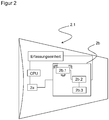
- eine schematische Darstellung eines Energiemoduls.
- In
Figur 1 ist ein beispielhaftes Warenregal (R) schematisch dargestellt, in dem das erfindungsgemäße Sensorsystem 1 installiert ist. Das erfindungsgemäße Sensorsystem 1 umfasst in diesem Ausführungsbeispiel eine Vielzahl von Sensoren 2.1 bis 2.4, die beispielsweise dafür vorgesehen sind, einen Belegungsgrad des Warenregals (R) zu erfassen. Der Belegungsgrad des Warenregals (R) ist im Sinne der Erfindung eine Menge an Paletten in den Fächern des Warenregals (R), wobei der Belegungsgrad durch das Sensorsystem 1 überwacht wird. - Die Sensoren 2.1 bis 2.4 stellen den erfassten Belegungsgrad des Warenregals (R) als Sensordaten zur Verfügung und kommunizieren diese Sensordaten drahtlos an zumindest einen Kommunikationsknoten 4. Der Kommunikationsknoten 4 selbst ist mittels eines Kabels mit einer Spannungsquelle verbunden, die den Kommunikationsknoten 4 mit Spannung versorgt.
- Vorteilhafterweise ist eine Steuerung 3 vorgesehen, die Sensordaten der Sensoren 2.1 bis 2.4 verarbeitet. Die Steuerung 3, beispielsweise ein übergeordnetes Lagerverwaltungssystem, erhält eine Information über den Belegungsgrad des Warenregals (R) übermittelt, so dass die Steuerung 3 beispielweise eine Aufstockung des Warenregals (R) veranlassen kann. Hierbei können vorzugsweise die Sensoren 2.1 bis 2.4 einen kapazitiven oder induktiven Sensor, oder ein RFID-Lesegerät umfassen. Ferner können die Sensoren 2.1 bis 2.4 auch jeweils einen optischen Sensor, wie einen Lichttaster, ein Lichtgitter, einen Scanner etc., umfassen.
- Die Sensoren 2.1 bis 2.4 weisen jeweils ein (in der Vergrößerungsansicht als Funktionsblock dargestelltes) Funkinterface 2a auf, das derart ausgebildet ist, dass das Funkinterface 2a Sensordaten an den Kommunikationsknoten 4 drahtlos übermittelt. Das Funkinterface 2a empfängt ferner Daten von dem Kommunikationsknoten 4. Die Kommunikation zwischen den Sensoren 2.1 bis 2.4 und dem Kommunikationsknoten 4 ist vorteilhafterweise kontinuierlich bzw. erfolgt entsprechend einem vorgegebenen Kommunikationszyklus, so dass der Kommunikationsknoten 4 immer über den aktuellen Belegungsgrad des Warenregals (R) informiert ist.
- Wie in der
Figur 2 dargestellt, umfassen die Sensoren 2.1 bis 2.4 jeweils ein Energiemodul 2b, das einen Empfänger 2b.1, einen Umsetzer 2b.2 und einen Energiespeicher 2b.3 umfasst. Der Empfänger 2b.1 ist derart ausgebildet, eine elektromagnetische Hochfrequenzstrahlung zu empfangen, die von dem Kommunikationsknoten 4 ausgesendet ist. Der Umsetzer 2b.2 ist derart ausgebildet, die Hochfrequenzenergie aus der Hochfrequenzstrahlung in elektrische Spannung umzusetzen, um damit den Energiespeicher 2b.3 zu laden und den jeweiligen Sensor 2.1, 2.2, 2.3 oder 2.4 mit der gespeicherten elektrischen Energie zu versorgen, so dass die Sensoren 2.1 bis 2.4 betrieben werden können. Hierbei umfassen der Empfänger 2b.1, der Umsetzer 2b.2 und der Energiespeicher 2b.3 insbesondere jeweils elektronische Elemente und Schaltungen, die die beschriebene Funktionalität ausführen können. Der Energiespeicher 2b.3 umfasst beispielsweise einen Kondensator oder einen Akku, so dass beispielsweise die gespeicherte elektrische Energie an die Erfassungseinheit des Sensors 2.1, 2.2, 2.3 oder 2.4 geliefert werden kann. - Mit anderen Worten, der Sensor 2.1, 2.2, 2.3 oder 2.4 erfasst bei dem dargestellten Beispiel mit seiner Erfassungseinheit die Belegung des Warenregals (R) und verarbeitet die Erfassung in einer CPU-Einheit zu Sensordaten, die dann von dem Funkinterface 2a an den Kommunikationsknoten 4 übermittelt werden. Die Erfassungseinheit kann bei einem Lichttaster als Sensor 2.1, 2.2, 2.3 oder 2.4 beispielweise einen Lichtsender und einen Lichtempfänger umfassen. Zusätzlich empfängt der Empfänger 2b.1 des Energiemoduls 2b die Hochfrequenzstrahlung von dem Kommunikationsknoten 4, wobei die Hochfrequenzstrahlung mit ihrer Hochfrequenzenergie durch den Umsetzer 2b.2 in die elektrische Spannung umgesetzt wird. Die elektrische Spannung dient zur Aufladung des Energiespeichers 2b.3, so dass der Energiespeicher 2b.3 den jeweiligen Sensor 2.1 bis 2.4 mit elektrischer Energie versorgt. Die von dem Kommunikationsknoten 4 empfangenen Daten können vorzugsweise Konfigurationsdaten oder Betriebsdaten für den Sensor 2.1, 2.2, 2.3 oder 2.4 sein. Ferner umfasst der Kommunikationsknoten 4 vorzugsweise eine, nicht dargestellte, Umwandlungseinheit, die aus der Versorgungsspannung des Kommunikationsknoten 4 die Hochfrequenzstrahlung erzeugt, wobei die Umwandlungseinheit ebenfalls elektronische Elemente und Schaltungen umfasst, die dazu ausgebildet sind, aus der Versorgungsspannung des Kommunikationsknoten 4 die Hochfrequenzstrahlung zu erzeugen.
- Hierdurch ist der Sensor 2.1, 2.2, 2.3 oder 2.4 des Sensorsystems 1 kabellos ausgebildet und eine Überwachung und ein Austausch einer üblicherweise bei kabellosem Sensor verwendeten Batterie können entfallen.
- Bezüglich einer bevorzugten Alternative und wie in der Vergrößerungsansicht der
Figur 1 dargestellt, empfangen die Sensoren 2.1 bis 2.4 jeweils vorzugsweise die Daten und die Hochfrequenzstrahlung des Kommunikationsknoten 4 auf einem ersten gemeinsamen Kanal und die Sensoren 2.1 bis 2.4 übermitteln jeweils die Sensordaten auf einem zweiten Kanal an den Kommunikationsknoten 4. - Entsprechend einer anderen bevorzugten Alternative sind die Sensordaten in einem Frequenzband übertragbar, das verschieden zu einem Frequenzband ist, in dem der Kommunikationsknoten 4 die Hochfrequenzstrahlung an dem jeweiligen Sensor 2.1, 2.2, 2.3 oder 2.4 übermittelt. Dadurch kann sicher vermieden werden, dass sich eine negative gegenseitige Beeinflussung bei der Übermittlung der Sensordaten und der Hochfrequenzstrahlung ergeben kann.
- Das Funkinterface 2a ist vorzugsweise zusammen mit dem Energiemodul 2b als ein einziges gemeinsames Modul, ein sogenanntes ASIC, ausgebildet. Hierdurch kann ein sehr kompakter und platzsparender Aufbau der Sensoren 2.1 bis 2.4 erzielt werden. Das Energiemodul 2b kann jedoch auch als separates Modul von dem Funkinterface 2a ausgebildet sein, so dass eine verbesserte elektrische Trennung zwischen dem Funkinterface 2a und dem Energiemodul 2b erzielt werden kann. Hierbei ergibt sich auch eine sichere Trennung zwischen den Sensordaten und der elektromagnetischen Hochfrequenzstrahlung, so dass die Kommunikation der Sensordaten nicht durch die Energieübertragung mittels der Hochfrequenzstrahlung gestört wird.
- Vorteilhafterweise kommuniziert der Kommunikationsknoten 4 insbesondere ein Aktivierungssignal an den jeweiligen Sensor 2.1, 2.2, 2.3 oder 2.4 bevor eine Übertragung der elektromagnetischen Hochfrequenzstrahlung durch den Kommunikationsknoten 4 ausführbar ist bzw. ausgeführt wird, wobei das Aktivierungssignal den jeweiligen Sensor 2.1, 2.2, 2.3 oder 2.4 für das Empfangen der Hochfrequenzstrahlung aktiviert. Dadurch ist es nicht notwendig, dass der Kommunikationsknoten 4 die Hochfrequenzstrahlung ständig, sondern zeitbasiert steuert oder bei Bedarfsanforderung des jeweiligen Sensors 2.1, 2.2, 2.3 oder 2.4 aussendet.
- Aus diesem Grund umfassen die Sensordaten, die von den Sensoren 2.1 bis 2.4 an den Kommunikationsknoten 4 übermittelt werden, insbesondere neben den Belegungsgrad des Warenregals (R) auch einen Energiestand des jeweiligen Sensors 2.1, 2.2, 2.3 oder 2.4. Das heißt, die Sensordaten geben nicht nur den Belegungsgrad des Warenregals (R), sondern auch den Energiestand des jeweiligen Sensors 2.1, 2.2, 2.3 oder 2.4 und damit den Bedarf einer Aufladung des jeweiligen Energiespeichers 2b.3 an den Kommunikationsknoten 4 wieder, so dass der Kommunikationsknoten 4 diese Information an die Steuerung 3 kommuniziert. Die Steuerung 3 kann bei Bedarf den Kommunikationsknoten 4 anweisen, die Hochfrequenzstrahlung an den jeweiligen Sensor 2.1, 2.2, 2.3 oder 2.4 zu übermitteln, um dessen Energiespeicher 2b.3 aufzuladen.
- Bei einer Vielzahl an Sensoren 2.1 bis 2.4 an dem Warenregal (R) kommunizieren die Sensoren 2.1 bis 2.4 vorteilhafterweise jeweils ein Identifizierungssignal zu dem Kommunikationsknoten 4, so dass der Kommunikationsknoten 4 die Sensoren 2.1 bis 2.4 eindeutig identifizieren und deren jeweiligen Aufladungsbedarf zuordnen kann.
- Die Sensoren 2.1 bis 2.4 übermitteln mit ihren Sensordaten ihre Betriebsbereitschaft, den Belegungsgrad des Warenregals (R), und ihren aktuellen Energiestand an den Kommunikationsknoten 4. Vorteilhafterweise priorisiert der Kommunikationsknoten 4 entsprechend des Energiestandes der Sensoren 2.1 bis 2.4 die Übertragung der Hochfrequenzwellen an die Sensoren 2.1 bis 2.4.
- Das heißt mit anderen Worten, der Kommunikationsknoten 4 erhält die Identifizierungssignale der Sensoren 2.1 bis 2.4 und deren Energiestand, so dass der Kommunikationsknoten 4 die Sensoren 2.1 bis 2.4 entsprechend ihres Energiebedarfs in eine Reihenfolge einteilt. Der Sensor, beispielsweise Sensor 2.1, mit dem niedrigsten Energiestand ist an erster Stelle der Reihe eingeteilt und der Sensor, beispielsweise Sensor 2.4, mit dem höchsten Energiestand ist an letzter Stelle der Reihe eingeteilt. Entsprechend der eingeteilten Reihenfolge kommuniziert der Kommunikationsknoten 4 beispielsweise zuerst das Aktivierungssignal für den Sensor 2.1 mit dem niedrigsten Energiestand, so dass dieser Sensor 2.1 mit der höchsten Priorität mit der elektromagnetischen Hochfrequenzstrahlung versorgt wird, um dessen Energiespeicher 2b.3 aufzuladen. Der Priorität bzw. Reihenfolge nach werden auf diese Weise die Sensoren 2.1 bis 2.4 mit der elektromagnetischen Hochfrequenzstrahlung versorgt, so dass die Energiespeicher 2b.3 der jeweiligen Sensoren 2.1 bis 2.4 entsprechend ihrem Energiestand der Reihenfolge nach aufgeladen werden können.
- Auf die Art und Weise ist sichergestellt, dass sämtliche Sensoren 2.1 bis 2.4 des Sensorsystems 1 entsprechend ihres Energiebedarfs rechtzeitig und kabellos mit Energie versorgt werden. Hierdurch ist die Betriebsbereitschaft der Sensoren 2.1 bis 2.4 des Sensorsystems 1 wartungsfrei und für eine sehr lange Laufzeit sichergestellt.
- Von der Steuerung 3 aus ist es möglich, dass Daten zum Konfigurieren der jeweiligen Sensoren 2.1 bis 2.4 bzw. des gesamten Sensorsystems 1 über den Kommunikationsknoten 4 kabellos an die Sensoren 2.1 bis 2.4 bzw. an das Sensorsystem 1 übermittelt werden. Zusätzlich kann die Steuerung 3 über den Kommunikationsknoten 4 die jeweiligen Sensoren 2.1 bis 2.4 zum Starten von Selbsttest veranlassen, so dass die Sensoren 2.1 bis 2.4 ein Ergebnis des eigenen Selbsttests zusammen mit dem Identifizierungssignal über den Kommunikationsknoten 4 an die Steuerung 3 zurück übermitteln. Dadurch ist die Steuerung 3 in der Lage, die Betriebsbereitschaft der Sensoren 2.1 bis 2.4 aus dem jeweiligen Testergebnis zu überprüfen und die Testergebnisse exakt den jeweiligen Sensoren 2.1 bis 2.4 durch das jeweilige Identifizierungssignal zuzuordnen.
- Hierdurch reduziert sich die Wartungsarbeit des Sensorsystems 1 erneut.
-
- 1
- Sensorsystem
- 2.1 bis 2.4
- Sensor
- 2a
- Funkinterface
- 2b
- Energiemodul
- 2b.1
- Empfänger
- 2b.2
- Umsetzer
- 2b.3
- Energiespeicher
- 3
- Steuerung
- 4
- Kommunikationsknoten
- R
- Warenregal
Claims (9)
- Sensorsystem (1) zur Überwachung einer Belegung eines Warenregals (R), umfassend:zumindest einen Sensor (2.1 bis 2.4), der die Belegung eines Faches des Warenregals (R) erfasst und als Sensordaten zur Verfügung stellt, undzumindest einen Kommunikationsknoten (4), der drahtlos mit dem Sensor (2.1 bis 2.4) kommuniziert,wobei der Sensor (2.1 bis 2.4) ein Funkinterface (2a) aufweist, das derart ausgebildet ist, dass das Funkinterface (2a) Sensordaten an den Kommunikationsknoten (4) drahtlos übermittelt sowie Daten von dem Kommunikationsknoten (4) drahtlos empfängt,dadurch gekennzeichnet, dass der Kommunikationsknoten (4) elektromagnetische Hochfrequenzstrahlung aussendet und der Sensor (2.1 bis 2.4) ein Energiemodul (2b) umfasst, wobei das Energiemodul (2b) einen Empfänger (2b.1), der die Hochfrequenzstrahlung empfängt, einen Umsetzer (2b.2), der Hochfrequenzenergie der Hochfrequenzstrahlung in elektrische Spannung umsetzt, und einen Energiespeicher (2b.3) aufweist, um den Sensor (2.1 bis 2.4) mit gespeicherter elektrischer Energie zu versorgen.
- Sensorsystem (1) nach Anspruch 1, dadurch gekennzeichnet, dass der Sensor (2.1 bis 2.4) einen optischen, kapazitiven oder induktiven Sensor, oder ein RFID-Lesegerät umfasst.
- Sensorsystem (1) nach Anspruch 1 oder 2, dadurch gekennzeichnet, dass der Sensor (2.1 bis 2.4) die Daten und Hochfrequenzstrahlung auf einem ersten gemeinsamen Kanal empfängt und die Sensordaten auf einem zweiten Kanal übermittelt.
- Sensorsystem (1) nach einem der vorhergehenden Ansprüche 1 bis 3, dadurch gekennzeichnet, dass der Kommunikationsknoten (4) ein Aktivierungssignal vor einer Übertragung der Hochfrequenzstrahlung durch den Kommunikationsknoten (4) kommuniziert, wobei das Aktivierungssignal den Sensor (2.1 bis 2.4) für das Empfangen der Hochfrequenzstrahlung aktiviert.
- Sensorsystem (1) nach einem der vorhergehenden Ansprüche 1 bis 4, dadurch gekennzeichnet, dass die Sensordaten die Belegung des Faches des Warenregals (R) und einen Energiestand des Sensors (2.1 bis 2.4) wiedergeben.
- Sensorsystem (1) nach Anspruch 5, dadurch gekennzeichnet, dass der Kommunikationsknoten (4) eine Übertragung der Hochfrequenzstrahlung an die Sensoren (2.1 bis 2.4) entsprechend dem Energiestand der Sensoren 2.1 bis 2.4) priorisiert.
- Sensorsystem (1) nach einem der vorhergehenden Ansprüche 1 bis 6, dadurch gekennzeichnet, dass die Sensordaten in einem Frequenzband übertragbar sind, das verschieden zu einem Frequenzband ist, in dem die Hochfrequenzstrahlung an den Sensor (2.1 bis 2.4) übermittelbar ist.
- Sensorsystem (1) nach einem der vorhergehenden Ansprüche 1 bis 7, dadurch gekennzeichnet, dass das Funkinterface (2a) und das Energiemodul (2b) zusammen als ein einziges gemeinsames Modul oder als separate Module ausgebildet sind.
- Sensorsystem (1) nach einem der vorhergehenden Ansprüche 1 bis 8, dadurch gekennzeichnet, dass der Energiespeicher (2b.3) des Energiemoduls (2b) einen Kondensator oder einen Akku umfasst.
Applications Claiming Priority (1)
| Application Number | Priority Date | Filing Date | Title |
|---|---|---|---|
| DE102018131114.1A DE102018131114A1 (de) | 2018-12-06 | 2018-12-06 | Sensorsystem zur Überwachung einer Belegung eines Warenregals |
Publications (2)
| Publication Number | Publication Date |
|---|---|
| EP3667637A1 true EP3667637A1 (de) | 2020-06-17 |
| EP3667637B1 EP3667637B1 (de) | 2022-04-27 |
Family
ID=68618047
Family Applications (1)
| Application Number | Title | Priority Date | Filing Date |
|---|---|---|---|
| EP19210059.2A Active EP3667637B1 (de) | 2018-12-06 | 2019-11-19 | Sensorsystem zur überwachung einer belegung eines warenregals |
Country Status (2)
| Country | Link |
|---|---|
| EP (1) | EP3667637B1 (de) |
| DE (1) | DE102018131114A1 (de) |
Citations (3)
| Publication number | Priority date | Publication date | Assignee | Title |
|---|---|---|---|---|
| EP1223057A2 (de) * | 2001-01-11 | 2002-07-17 | The Yokohama Rubber Co., Ltd. | Transponder, Abfragegeräte und System damit |
| US20120132710A1 (en) * | 2009-04-30 | 2012-05-31 | Friedrich-Alexander-Universitaet Erlangen-Nuernberg | Apparatus and method for supplying an rfid component with energy |
| DE202014004232U1 (de) | 2014-05-22 | 2015-08-26 | Kesseböhmer Holding e.K. | Warenregal zur Selbstbedienungsentnahme von Backwaren |
Family Cites Families (1)
| Publication number | Priority date | Publication date | Assignee | Title |
|---|---|---|---|---|
| DE102016213239B4 (de) * | 2016-02-12 | 2018-12-20 | Fraunhofer-Gesellschaft zur Förderung der angewandten Forschung e.V. | Vorrichtung zur kommunikation mit kommunikationsvorrichtungen, entsprechende kommunikationsvorrichtung und verfahren |
-
2018
- 2018-12-06 DE DE102018131114.1A patent/DE102018131114A1/de not_active Withdrawn
-
2019
- 2019-11-19 EP EP19210059.2A patent/EP3667637B1/de active Active
Patent Citations (3)
| Publication number | Priority date | Publication date | Assignee | Title |
|---|---|---|---|---|
| EP1223057A2 (de) * | 2001-01-11 | 2002-07-17 | The Yokohama Rubber Co., Ltd. | Transponder, Abfragegeräte und System damit |
| US20120132710A1 (en) * | 2009-04-30 | 2012-05-31 | Friedrich-Alexander-Universitaet Erlangen-Nuernberg | Apparatus and method for supplying an rfid component with energy |
| DE202014004232U1 (de) | 2014-05-22 | 2015-08-26 | Kesseböhmer Holding e.K. | Warenregal zur Selbstbedienungsentnahme von Backwaren |
Non-Patent Citations (1)
| Title |
|---|
| DANIEL J YEAGER ET AL: "Wirelessly-Charged UHF Tags for Sensor Data Collection", RFID, 2008 IEEE INTERNATIONAL CONFERENCE ON, IEEE, PISCATAWAY, NJ, USA, 16 April 2008 (2008-04-16), pages 320 - 327, XP031252203, ISBN: 978-1-4244-1711-7 * |
Also Published As
| Publication number | Publication date |
|---|---|
| EP3667637B1 (de) | 2022-04-27 |
| DE102018131114A1 (de) | 2020-06-10 |
Similar Documents
| Publication | Publication Date | Title |
|---|---|---|
| EP3844854B1 (de) | Akkupack sowie ladeverfahren für ein akkupack | |
| EP3209518B1 (de) | Verfahren zum betrieb einer energiespeichereinrichtung in einem kraftfahrzeug und kraftfahrzeug | |
| EP3198567B1 (de) | Daten- und messerfassungsvorrichtung für einen türgriff sowie verfahren dazu | |
| DE112017005816T5 (de) | Fahrzeugbatterieüberwachungsvorrichtung und fahrzeugbatterieüberwachungssystem | |
| DE19832628A1 (de) | Transponderanordnung | |
| DE102012210253A1 (de) | Verfahren zum Überwachen einer Batterie | |
| DE102017223665B4 (de) | Elektrisches Batteriemodul | |
| EP3452966B1 (de) | Lagerlogistik-verfahren | |
| WO2020239795A1 (de) | Entriegelungssystem und schlossanordnung mit einem derartigen entriegelungssystem | |
| EP4016782A1 (de) | Mehrplatzladegerät und akkupack-mehrplatzladegerät-set | |
| EP2595218A1 (de) | Verfahren zum Überwachen einer Batterie | |
| EP1468863B1 (de) | Anlage und Verfahren zur Überwachung einer elektrischen Batterie in einem Unterseeboot | |
| EP3667637B1 (de) | Sensorsystem zur überwachung einer belegung eines warenregals | |
| DE202018106954U1 (de) | Sensorsystem zur Überwachung einer Belegung eines Warenregals | |
| WO2013117714A1 (de) | Vorrichtung zum überwachen einer verteilstelle | |
| EP1975967B1 (de) | Schaltgerät mit einer Einrichtung zur drahtlosen Übertragung einer Gerätezustandsinformation | |
| DE102014222440A1 (de) | Batteriesystem und Vorrichtung zur Übertragung von Signalen innerhalb des Batteriesystems | |
| WO2012038148A1 (de) | Batteriesystem zur messung von batteriemodulspannungen | |
| DE102004053696A1 (de) | Reifendruckkontrollsystem für ein Kraftfahrzeug | |
| DE102015117011A1 (de) | Energieversorgungseinheit für ein Funkmodul | |
| DE102012006247A1 (de) | Vorrichtung und Verfahren zum Betreiben einer Energiespeichervorrichtung | |
| EP3898454A1 (de) | Lager- und kommissioniersystem und verfahren zum konfigurieren eines fahrzeugs | |
| EP2448000B1 (de) | Photovoltaikanlage und Verfahren dazu | |
| DE102021109513A1 (de) | Verfahren zur Wartung von Anlagen, insbesondere Maschinen in Warenlagern | |
| DE202013100811U1 (de) | Energieversorgungseinrichtung mit Batterieüberwachung |
Legal Events
| Date | Code | Title | Description |
|---|---|---|---|
| PUAI | Public reference made under article 153(3) epc to a published international application that has entered the european phase |
Free format text: ORIGINAL CODE: 0009012 |
|
| STAA | Information on the status of an ep patent application or granted ep patent |
Free format text: STATUS: THE APPLICATION HAS BEEN PUBLISHED |
|
| AK | Designated contracting states |
Kind code of ref document: A1 Designated state(s): AL AT BE BG CH CY CZ DE DK EE ES FI FR GB GR HR HU IE IS IT LI LT LU LV MC MK MT NL NO PL PT RO RS SE SI SK SM TR |
|
| AX | Request for extension of the european patent |
Extension state: BA ME |
|
| STAA | Information on the status of an ep patent application or granted ep patent |
Free format text: STATUS: REQUEST FOR EXAMINATION WAS MADE |
|
| 17P | Request for examination filed |
Effective date: 20201217 |
|
| RBV | Designated contracting states (corrected) |
Designated state(s): AL AT BE BG CH CY CZ DE DK EE ES FI FR GB GR HR HU IE IS IT LI LT LU LV MC MK MT NL NO PL PT RO RS SE SI SK SM TR |
|
| GRAP | Despatch of communication of intention to grant a patent |
Free format text: ORIGINAL CODE: EPIDOSNIGR1 |
|
| STAA | Information on the status of an ep patent application or granted ep patent |
Free format text: STATUS: GRANT OF PATENT IS INTENDED |
|
| INTG | Intention to grant announced |
Effective date: 20220111 |
|
| GRAJ | Information related to disapproval of communication of intention to grant by the applicant or resumption of examination proceedings by the epo deleted |
Free format text: ORIGINAL CODE: EPIDOSDIGR1 |
|
| STAA | Information on the status of an ep patent application or granted ep patent |
Free format text: STATUS: REQUEST FOR EXAMINATION WAS MADE |
|
| GRAS | Grant fee paid |
Free format text: ORIGINAL CODE: EPIDOSNIGR3 |
|
| STAA | Information on the status of an ep patent application or granted ep patent |
Free format text: STATUS: GRANT OF PATENT IS INTENDED |
|
| INTC | Intention to grant announced (deleted) | ||
| GRAP | Despatch of communication of intention to grant a patent |
Free format text: ORIGINAL CODE: EPIDOSNIGR1 |
|
| GRAA | (expected) grant |
Free format text: ORIGINAL CODE: 0009210 |
|
| STAA | Information on the status of an ep patent application or granted ep patent |
Free format text: STATUS: THE PATENT HAS BEEN GRANTED |
|
| INTG | Intention to grant announced |
Effective date: 20220318 |
|
| AK | Designated contracting states |
Kind code of ref document: B1 Designated state(s): AL AT BE BG CH CY CZ DE DK EE ES FI FR GB GR HR HU IE IS IT LI LT LU LV MC MK MT NL NO PL PT RO RS SE SI SK SM TR |
|
| REG | Reference to a national code |
Ref country code: GB Ref legal event code: FG4D Free format text: NOT ENGLISH |
|
| REG | Reference to a national code |
Ref country code: CH Ref legal event code: EP |
|
| REG | Reference to a national code |
Ref country code: AT Ref legal event code: REF Ref document number: 1487552 Country of ref document: AT Kind code of ref document: T Effective date: 20220515 |
|
| REG | Reference to a national code |
Ref country code: DE Ref legal event code: R096 Ref document number: 502019004187 Country of ref document: DE |
|
| REG | Reference to a national code |
Ref country code: IE Ref legal event code: FG4D Free format text: LANGUAGE OF EP DOCUMENT: GERMAN |
|
| REG | Reference to a national code |
Ref country code: LT Ref legal event code: MG9D |
|
| REG | Reference to a national code |
Ref country code: NL Ref legal event code: MP Effective date: 20220427 |
|
| PG25 | Lapsed in a contracting state [announced via postgrant information from national office to epo] |
Ref country code: NL Free format text: LAPSE BECAUSE OF FAILURE TO SUBMIT A TRANSLATION OF THE DESCRIPTION OR TO PAY THE FEE WITHIN THE PRESCRIBED TIME-LIMIT Effective date: 20220427 |
|
| PG25 | Lapsed in a contracting state [announced via postgrant information from national office to epo] |
Ref country code: SE Free format text: LAPSE BECAUSE OF FAILURE TO SUBMIT A TRANSLATION OF THE DESCRIPTION OR TO PAY THE FEE WITHIN THE PRESCRIBED TIME-LIMIT Effective date: 20220427 Ref country code: PT Free format text: LAPSE BECAUSE OF FAILURE TO SUBMIT A TRANSLATION OF THE DESCRIPTION OR TO PAY THE FEE WITHIN THE PRESCRIBED TIME-LIMIT Effective date: 20220829 Ref country code: NO Free format text: LAPSE BECAUSE OF FAILURE TO SUBMIT A TRANSLATION OF THE DESCRIPTION OR TO PAY THE FEE WITHIN THE PRESCRIBED TIME-LIMIT Effective date: 20220727 Ref country code: LT Free format text: LAPSE BECAUSE OF FAILURE TO SUBMIT A TRANSLATION OF THE DESCRIPTION OR TO PAY THE FEE WITHIN THE PRESCRIBED TIME-LIMIT Effective date: 20220427 Ref country code: HR Free format text: LAPSE BECAUSE OF FAILURE TO SUBMIT A TRANSLATION OF THE DESCRIPTION OR TO PAY THE FEE WITHIN THE PRESCRIBED TIME-LIMIT Effective date: 20220427 Ref country code: GR Free format text: LAPSE BECAUSE OF FAILURE TO SUBMIT A TRANSLATION OF THE DESCRIPTION OR TO PAY THE FEE WITHIN THE PRESCRIBED TIME-LIMIT Effective date: 20220728 Ref country code: FI Free format text: LAPSE BECAUSE OF FAILURE TO SUBMIT A TRANSLATION OF THE DESCRIPTION OR TO PAY THE FEE WITHIN THE PRESCRIBED TIME-LIMIT Effective date: 20220427 Ref country code: ES Free format text: LAPSE BECAUSE OF FAILURE TO SUBMIT A TRANSLATION OF THE DESCRIPTION OR TO PAY THE FEE WITHIN THE PRESCRIBED TIME-LIMIT Effective date: 20220427 Ref country code: BG Free format text: LAPSE BECAUSE OF FAILURE TO SUBMIT A TRANSLATION OF THE DESCRIPTION OR TO PAY THE FEE WITHIN THE PRESCRIBED TIME-LIMIT Effective date: 20220727 |
|
| PG25 | Lapsed in a contracting state [announced via postgrant information from national office to epo] |
Ref country code: RS Free format text: LAPSE BECAUSE OF FAILURE TO SUBMIT A TRANSLATION OF THE DESCRIPTION OR TO PAY THE FEE WITHIN THE PRESCRIBED TIME-LIMIT Effective date: 20220427 Ref country code: PL Free format text: LAPSE BECAUSE OF FAILURE TO SUBMIT A TRANSLATION OF THE DESCRIPTION OR TO PAY THE FEE WITHIN THE PRESCRIBED TIME-LIMIT Effective date: 20220427 Ref country code: LV Free format text: LAPSE BECAUSE OF FAILURE TO SUBMIT A TRANSLATION OF THE DESCRIPTION OR TO PAY THE FEE WITHIN THE PRESCRIBED TIME-LIMIT Effective date: 20220427 Ref country code: IS Free format text: LAPSE BECAUSE OF FAILURE TO SUBMIT A TRANSLATION OF THE DESCRIPTION OR TO PAY THE FEE WITHIN THE PRESCRIBED TIME-LIMIT Effective date: 20220827 |
|
| REG | Reference to a national code |
Ref country code: DE Ref legal event code: R097 Ref document number: 502019004187 Country of ref document: DE |
|
| PG25 | Lapsed in a contracting state [announced via postgrant information from national office to epo] |
Ref country code: SM Free format text: LAPSE BECAUSE OF FAILURE TO SUBMIT A TRANSLATION OF THE DESCRIPTION OR TO PAY THE FEE WITHIN THE PRESCRIBED TIME-LIMIT Effective date: 20220427 Ref country code: SK Free format text: LAPSE BECAUSE OF FAILURE TO SUBMIT A TRANSLATION OF THE DESCRIPTION OR TO PAY THE FEE WITHIN THE PRESCRIBED TIME-LIMIT Effective date: 20220427 Ref country code: RO Free format text: LAPSE BECAUSE OF FAILURE TO SUBMIT A TRANSLATION OF THE DESCRIPTION OR TO PAY THE FEE WITHIN THE PRESCRIBED TIME-LIMIT Effective date: 20220427 Ref country code: EE Free format text: LAPSE BECAUSE OF FAILURE TO SUBMIT A TRANSLATION OF THE DESCRIPTION OR TO PAY THE FEE WITHIN THE PRESCRIBED TIME-LIMIT Effective date: 20220427 Ref country code: DK Free format text: LAPSE BECAUSE OF FAILURE TO SUBMIT A TRANSLATION OF THE DESCRIPTION OR TO PAY THE FEE WITHIN THE PRESCRIBED TIME-LIMIT Effective date: 20220427 Ref country code: CZ Free format text: LAPSE BECAUSE OF FAILURE TO SUBMIT A TRANSLATION OF THE DESCRIPTION OR TO PAY THE FEE WITHIN THE PRESCRIBED TIME-LIMIT Effective date: 20220427 |
|
| PLBE | No opposition filed within time limit |
Free format text: ORIGINAL CODE: 0009261 |
|
| STAA | Information on the status of an ep patent application or granted ep patent |
Free format text: STATUS: NO OPPOSITION FILED WITHIN TIME LIMIT |
|
| PG25 | Lapsed in a contracting state [announced via postgrant information from national office to epo] |
Ref country code: AL Free format text: LAPSE BECAUSE OF FAILURE TO SUBMIT A TRANSLATION OF THE DESCRIPTION OR TO PAY THE FEE WITHIN THE PRESCRIBED TIME-LIMIT Effective date: 20220427 |
|
| 26N | No opposition filed |
Effective date: 20230130 |
|
| PG25 | Lapsed in a contracting state [announced via postgrant information from national office to epo] |
Ref country code: SI Free format text: LAPSE BECAUSE OF FAILURE TO SUBMIT A TRANSLATION OF THE DESCRIPTION OR TO PAY THE FEE WITHIN THE PRESCRIBED TIME-LIMIT Effective date: 20220427 |
|
| PG25 | Lapsed in a contracting state [announced via postgrant information from national office to epo] |
Ref country code: MC Free format text: LAPSE BECAUSE OF FAILURE TO SUBMIT A TRANSLATION OF THE DESCRIPTION OR TO PAY THE FEE WITHIN THE PRESCRIBED TIME-LIMIT Effective date: 20220427 |
|
| REG | Reference to a national code |
Ref country code: CH Ref legal event code: PL |
|
| REG | Reference to a national code |
Ref country code: BE Ref legal event code: MM Effective date: 20221130 |
|
| PG25 | Lapsed in a contracting state [announced via postgrant information from national office to epo] |
Ref country code: LI Free format text: LAPSE BECAUSE OF NON-PAYMENT OF DUE FEES Effective date: 20221130 Ref country code: CH Free format text: LAPSE BECAUSE OF NON-PAYMENT OF DUE FEES Effective date: 20221130 |
|
| PG25 | Lapsed in a contracting state [announced via postgrant information from national office to epo] |
Ref country code: LU Free format text: LAPSE BECAUSE OF NON-PAYMENT OF DUE FEES Effective date: 20221119 |
|
| PG25 | Lapsed in a contracting state [announced via postgrant information from national office to epo] |
Ref country code: IE Free format text: LAPSE BECAUSE OF NON-PAYMENT OF DUE FEES Effective date: 20221119 |
|
| PG25 | Lapsed in a contracting state [announced via postgrant information from national office to epo] |
Ref country code: FR Free format text: LAPSE BECAUSE OF NON-PAYMENT OF DUE FEES Effective date: 20221130 Ref country code: BE Free format text: LAPSE BECAUSE OF NON-PAYMENT OF DUE FEES Effective date: 20221130 |
|
| PG25 | Lapsed in a contracting state [announced via postgrant information from national office to epo] |
Ref country code: HU Free format text: LAPSE BECAUSE OF FAILURE TO SUBMIT A TRANSLATION OF THE DESCRIPTION OR TO PAY THE FEE WITHIN THE PRESCRIBED TIME-LIMIT; INVALID AB INITIO Effective date: 20191119 |
|
| PG25 | Lapsed in a contracting state [announced via postgrant information from national office to epo] |
Ref country code: CY Free format text: LAPSE BECAUSE OF FAILURE TO SUBMIT A TRANSLATION OF THE DESCRIPTION OR TO PAY THE FEE WITHIN THE PRESCRIBED TIME-LIMIT Effective date: 20220427 |
|
| PG25 | Lapsed in a contracting state [announced via postgrant information from national office to epo] |
Ref country code: MK Free format text: LAPSE BECAUSE OF FAILURE TO SUBMIT A TRANSLATION OF THE DESCRIPTION OR TO PAY THE FEE WITHIN THE PRESCRIBED TIME-LIMIT Effective date: 20220427 |
|
| GBPC | Gb: european patent ceased through non-payment of renewal fee |
Effective date: 20231119 |
|
| PG25 | Lapsed in a contracting state [announced via postgrant information from national office to epo] |
Ref country code: MT Free format text: LAPSE BECAUSE OF FAILURE TO SUBMIT A TRANSLATION OF THE DESCRIPTION OR TO PAY THE FEE WITHIN THE PRESCRIBED TIME-LIMIT Effective date: 20220427 |
|
| PG25 | Lapsed in a contracting state [announced via postgrant information from national office to epo] |
Ref country code: GB Free format text: LAPSE BECAUSE OF NON-PAYMENT OF DUE FEES Effective date: 20231119 |
|
| PG25 | Lapsed in a contracting state [announced via postgrant information from national office to epo] |
Ref country code: GB Free format text: LAPSE BECAUSE OF NON-PAYMENT OF DUE FEES Effective date: 20231119 |
|
| PG25 | Lapsed in a contracting state [announced via postgrant information from national office to epo] |
Ref country code: BG Free format text: LAPSE BECAUSE OF FAILURE TO SUBMIT A TRANSLATION OF THE DESCRIPTION OR TO PAY THE FEE WITHIN THE PRESCRIBED TIME-LIMIT Effective date: 20220427 |
|
| PG25 | Lapsed in a contracting state [announced via postgrant information from national office to epo] |
Ref country code: BG Free format text: LAPSE BECAUSE OF FAILURE TO SUBMIT A TRANSLATION OF THE DESCRIPTION OR TO PAY THE FEE WITHIN THE PRESCRIBED TIME-LIMIT Effective date: 20220427 |
|
| PG25 | Lapsed in a contracting state [announced via postgrant information from national office to epo] |
Ref country code: TR Free format text: LAPSE BECAUSE OF FAILURE TO SUBMIT A TRANSLATION OF THE DESCRIPTION OR TO PAY THE FEE WITHIN THE PRESCRIBED TIME-LIMIT Effective date: 20220427 |
|
| PGFP | Annual fee paid to national office [announced via postgrant information from national office to epo] |
Ref country code: DE Payment date: 20251118 Year of fee payment: 7 |
|
| PGFP | Annual fee paid to national office [announced via postgrant information from national office to epo] |
Ref country code: AT Payment date: 20251117 Year of fee payment: 7 |
|
| PGFP | Annual fee paid to national office [announced via postgrant information from national office to epo] |
Ref country code: IT Payment date: 20251128 Year of fee payment: 7 |