EP3667556A1 - Autonomer spurwechsel - Google Patents
Autonomer spurwechsel Download PDFInfo
- Publication number
- EP3667556A1 EP3667556A1 EP18212102.0A EP18212102A EP3667556A1 EP 3667556 A1 EP3667556 A1 EP 3667556A1 EP 18212102 A EP18212102 A EP 18212102A EP 3667556 A1 EP3667556 A1 EP 3667556A1
- Authority
- EP
- European Patent Office
- Prior art keywords
- vehicular
- sensory
- lane
- ego vehicle
- vehicle
- Prior art date
- Legal status (The legal status is an assumption and is not a legal conclusion. Google has not performed a legal analysis and makes no representation as to the accuracy of the status listed.)
- Withdrawn
Links
- 230000001953 sensory effect Effects 0.000 claims abstract description 85
- 238000000034 method Methods 0.000 claims abstract description 30
- 230000004927 fusion Effects 0.000 claims abstract description 23
- 230000000977 initiatory effect Effects 0.000 claims abstract description 18
- 238000013528 artificial neural network Methods 0.000 claims abstract description 17
- 230000002787 reinforcement Effects 0.000 claims abstract description 15
- 230000003068 static effect Effects 0.000 claims description 14
- 238000003491 array Methods 0.000 claims description 2
- 238000012545 processing Methods 0.000 claims description 2
- 238000005457 optimization Methods 0.000 abstract description 10
- 238000013459 approach Methods 0.000 description 6
- 238000004364 calculation method Methods 0.000 description 5
- 238000004088 simulation Methods 0.000 description 4
- 230000001133 acceleration Effects 0.000 description 2
- 238000004422 calculation algorithm Methods 0.000 description 2
- 238000010586 diagram Methods 0.000 description 2
- 235000004240 Triticum spelta Nutrition 0.000 description 1
- 238000003066 decision tree Methods 0.000 description 1
- 238000013461 design Methods 0.000 description 1
- 230000007613 environmental effect Effects 0.000 description 1
- 230000006870 function Effects 0.000 description 1
- 238000005259 measurement Methods 0.000 description 1
- 238000012360 testing method Methods 0.000 description 1
- 238000010200 validation analysis Methods 0.000 description 1
Images


Classifications
-
- B—PERFORMING OPERATIONS; TRANSPORTING
- B60—VEHICLES IN GENERAL
- B60W—CONJOINT CONTROL OF VEHICLE SUB-UNITS OF DIFFERENT TYPE OR DIFFERENT FUNCTION; CONTROL SYSTEMS SPECIALLY ADAPTED FOR HYBRID VEHICLES; ROAD VEHICLE DRIVE CONTROL SYSTEMS FOR PURPOSES NOT RELATED TO THE CONTROL OF A PARTICULAR SUB-UNIT
- B60W30/00—Purposes of road vehicle drive control systems not related to the control of a particular sub-unit, e.g. of systems using conjoint control of vehicle sub-units, or advanced driver assistance systems for ensuring comfort, stability and safety or drive control systems for propelling or retarding the vehicle
- B60W30/18—Propelling the vehicle
- B60W30/18009—Propelling the vehicle related to particular drive situations
- B60W30/18163—Lane change; Overtaking manoeuvres
-
- B—PERFORMING OPERATIONS; TRANSPORTING
- B60—VEHICLES IN GENERAL
- B60W—CONJOINT CONTROL OF VEHICLE SUB-UNITS OF DIFFERENT TYPE OR DIFFERENT FUNCTION; CONTROL SYSTEMS SPECIALLY ADAPTED FOR HYBRID VEHICLES; ROAD VEHICLE DRIVE CONTROL SYSTEMS FOR PURPOSES NOT RELATED TO THE CONTROL OF A PARTICULAR SUB-UNIT
- B60W50/00—Details of control systems for road vehicle drive control not related to the control of a particular sub-unit, e.g. process diagnostic or vehicle driver interfaces
-
- B—PERFORMING OPERATIONS; TRANSPORTING
- B60—VEHICLES IN GENERAL
- B60W—CONJOINT CONTROL OF VEHICLE SUB-UNITS OF DIFFERENT TYPE OR DIFFERENT FUNCTION; CONTROL SYSTEMS SPECIALLY ADAPTED FOR HYBRID VEHICLES; ROAD VEHICLE DRIVE CONTROL SYSTEMS FOR PURPOSES NOT RELATED TO THE CONTROL OF A PARTICULAR SUB-UNIT
- B60W60/00—Drive control systems specially adapted for autonomous road vehicles
- B60W60/001—Planning or execution of driving tasks
- B60W60/0011—Planning or execution of driving tasks involving control alternatives for a single driving scenario, e.g. planning several paths to avoid obstacles
-
- G—PHYSICS
- G05—CONTROLLING; REGULATING
- G05D—SYSTEMS FOR CONTROLLING OR REGULATING NON-ELECTRIC VARIABLES
- G05D1/00—Control of position, course or altitude of land, water, air, or space vehicles, e.g. automatic pilot
- G05D1/0088—Control of position, course or altitude of land, water, air, or space vehicles, e.g. automatic pilot characterized by the autonomous decision making process, e.g. artificial intelligence, predefined behaviours
-
- G—PHYSICS
- G06—COMPUTING; CALCULATING OR COUNTING
- G06F—ELECTRIC DIGITAL DATA PROCESSING
- G06F18/00—Pattern recognition
- G06F18/20—Analysing
- G06F18/21—Design or setup of recognition systems or techniques; Extraction of features in feature space; Blind source separation
- G06F18/214—Generating training patterns; Bootstrap methods, e.g. bagging or boosting
-
- G—PHYSICS
- G06—COMPUTING; CALCULATING OR COUNTING
- G06F—ELECTRIC DIGITAL DATA PROCESSING
- G06F18/00—Pattern recognition
- G06F18/20—Analysing
- G06F18/29—Graphical models, e.g. Bayesian networks
- G06F18/295—Markov models or related models, e.g. semi-Markov models; Markov random fields; Networks embedding Markov models
-
- G—PHYSICS
- G06—COMPUTING; CALCULATING OR COUNTING
- G06N—COMPUTING ARRANGEMENTS BASED ON SPECIFIC COMPUTATIONAL MODELS
- G06N3/00—Computing arrangements based on biological models
- G06N3/02—Neural networks
- G06N3/08—Learning methods
-
- G—PHYSICS
- G06—COMPUTING; CALCULATING OR COUNTING
- G06V—IMAGE OR VIDEO RECOGNITION OR UNDERSTANDING
- G06V20/00—Scenes; Scene-specific elements
- G06V20/50—Context or environment of the image
- G06V20/56—Context or environment of the image exterior to a vehicle by using sensors mounted on the vehicle
- G06V20/588—Recognition of the road, e.g. of lane markings; Recognition of the vehicle driving pattern in relation to the road
-
- B—PERFORMING OPERATIONS; TRANSPORTING
- B60—VEHICLES IN GENERAL
- B60W—CONJOINT CONTROL OF VEHICLE SUB-UNITS OF DIFFERENT TYPE OR DIFFERENT FUNCTION; CONTROL SYSTEMS SPECIALLY ADAPTED FOR HYBRID VEHICLES; ROAD VEHICLE DRIVE CONTROL SYSTEMS FOR PURPOSES NOT RELATED TO THE CONTROL OF A PARTICULAR SUB-UNIT
- B60W50/00—Details of control systems for road vehicle drive control not related to the control of a particular sub-unit, e.g. process diagnostic or vehicle driver interfaces
- B60W2050/0062—Adapting control system settings
- B60W2050/0075—Automatic parameter input, automatic initialising or calibrating means
- B60W2050/0083—Setting, resetting, calibration
- B60W2050/0088—Adaptive recalibration
-
- B—PERFORMING OPERATIONS; TRANSPORTING
- B60—VEHICLES IN GENERAL
- B60W—CONJOINT CONTROL OF VEHICLE SUB-UNITS OF DIFFERENT TYPE OR DIFFERENT FUNCTION; CONTROL SYSTEMS SPECIALLY ADAPTED FOR HYBRID VEHICLES; ROAD VEHICLE DRIVE CONTROL SYSTEMS FOR PURPOSES NOT RELATED TO THE CONTROL OF A PARTICULAR SUB-UNIT
- B60W2420/00—Indexing codes relating to the type of sensors based on the principle of their operation
- B60W2420/40—Photo or light sensitive means, e.g. infrared sensors
- B60W2420/403—Image sensing, e.g. optical camera
Definitions
- This disclosure relates to system, and method for automatically initiating a change of lane in an automated automotive vehicle, and in particular relates to the optimization and use of a SAE Level-4 automated lane change system that employs reinforcement learning.
- Automated self-driving automotive vehicles (sometimes called autonomous vehicles), particularly cars, are capable of sensing the surrounding environment and moving and manoeuvring with little or no human input.
- Automated cars typically combine a variety of sensors to perceive their surroundings, such as radar, computer vision, Lidar, sonar, GPS, odometry and inertial measurements.
- Automated control systems interpret the sensory information to identify appropriate navigation paths, as well as obstacles and relevant signage.
- Level 4 The standards body SAE International defines the second highest level of automated driving system as "Level 4", in which the driving mode-specific performance by an automated driving system controls all aspects of the dynamic driving task, even if a human driver does not respond appropriately to a request to intervene.
- One of the more difficult manoeuvres to perform safely is a lane change, for example to maintain a desired set speed by moving out into a faster lane, or to move back into a slower lane to allow following traffic to overtake. It is particularly difficult to automate the decision in real time as to when it is safe to make a lane change.
- One aspect of this disclosure relates to a method of optimizing an automated lane change system for use with a vehicular automated driving system of an ego vehicle, the lane change system comprising a plurality of sensory inputs each for receiving corresponding sensory data, a sensory fusion processor for combining the sensory data, and a reinforcement learning system.
- Sensory data from disparate sources is provided to the sensory inputs, this data being representative of a sensed vehicular driving environment of the ego vehicle.
- the vehicular driving environment comprises at least two lanes of traffic flowing along the same roadway.
- the sensory data is combined in the sensory fusion processor to generate a semantic image of the sensed vehicular driving environment.
- the semantic image is a simplified static representation in two dimensions of the vehicular driving environment at the time the sensory data was provided to the sensory inputs. The dimensions extend along the roadway both ahead and behind the ego vehicle and laterally across the roadway lanes.
- the sensory fusion processor is used to repeatedly generate the semantic images.
- the semantic images together provide a sequence of at least two of the static representations of the vehicular driving environment at corresponding times during which the ego vehicle travels in a first one of the lanes along the roadway.
- the semantic images are then provided to a reinforcement learning system that employs a Markov Decision Process (MDP).
- MDP Markov Decision Process
- the two dimensions of each semantic image are divided into cells and provide to the MDP a MDP grid-world.
- the ego vehicle is represented as an agent in the MDP.
- the lane in which the ego vehicle travels is represented by an agent state in the MDP grid-world.
- Reinforcement learning is then used to solve the MDP for a change of the agent state representing a successful change of lane of the ego vehicle.
- the solution of the MDP is then used in the automated lane change system, whereby, in use, the automated lane change system provides at an output of the automated lane change system a signal representative of a yes/no decision for initiating a lane change during automated driving of the ego vehicle by the vehicular automated driving system.
- the sensory data is preferably provided by a driving simulation system that provides simulated real-world data.
- the semantic image is stripped of information representing curves in the lanes of the vehicular driving environment.
- lane width is sensed so that an average lane width is generated and used for the semantic image.
- the lanes in the semantic image are represented by parallel arrays of the cells in the MDP grid-world.
- the cells will, in general, be rectangular or square cells with sides aligned parallel and perpendicular to a longitudinal direction of the lanes,
- the ego vehicle and each other vehicle sensed in the vehicular driving environment in the sematic image is represented by a block of the cells in the MDP grid-world.
- Each of these blocks preferably has the same size and shape regardless of a sensed length or width of each of the other vehicles.
- each block representing a vehicle behind the ego vehicle on the roadway then corresponds with a sensed front edge of this particular vehicle.
- each block representing a vehicle in front of the ego vehicle on the roadway then corresponds with a sensed rear edge of this particular vehicle.
- Another aspect of this disclosure relates to a method of using a vehicular automated driving system to drive automatically an ego vehicle in a vehicular driving environment comprising at least two lanes of traffic flowing along the same roadway.
- the vehicular automated driving system comprises an automated lane change system, the lane change system comprising a plurality of sensory inputs each for receiving corresponding sensory data, a sensory fusion processor for combining the sensory data, and a neural network for generating a yes / no decision for initiating a lane change from a first lane of the roadway to a second lane of the roadway.
- the method comprises:
- the vehicular automated driving system is used to calculate a trajectory for the forthcoming lane change, and after the trajectory has been calculated, the vehicular automated driving system is used to move the vehicle from the first lane to the second lane along the calculated trajectory.
- the semantic image may be stripped of information representing roadway curves so that lanes in the semantic image are represented by parallel strips in the grid-like representation in two dimensions of the vehicular driving environment.
- the ego vehicle and each other vehicle sensed in the vehicular driving environment in the sematic image may be represented by blocks in the grid-like representation in two dimensions of the vehicular driving environment.
- Each of the blocks most preferably has the same size and shape regardless of a sensed length or width of each of the other vehicles.
- each block preferably represents a sensed front edge of a following vehicle on the roadway.
- each block preferably represents a sensed trailing edge of a leading vehicle o the roadway.
- a vehicular automated driving system for driving automatically an ego vehicle in a vehicular driving environment, the environment comprising at least two lanes of traffic flowing along the same roadway, and the vehicular automated driving system comprising an automated lane change system, the lane change system comprising a plurality of sensory inputs each for receiving corresponding sensory data, a sensory fusion processor for combining the sensory data, and a neural network for generating a yes / no decision for initiating a lane change from a first lane of the roadway to a second lane of the roadway.
- the vehicular automated driving system is configured, in use, to:
- the vehicular automated driving system then acts on the decision being in the affirmative to calculate a trajectory for the forthcoming lane change, and after the trajectory has been calculated, act to control the vehicle, for example through a control data bus linked to a vehicle motor, steering system and braking system, to move the vehicle from the first lane to the second lane along the calculated trajectory.
- the sensory data of the vehicle operating environment may be provided by any suitable sensors, depending on the vehicle operating parameter or the environmental physical feature to be sensed.
- suitable sensors include a vehicle speed sensor, a vehicle accelerometer, radar, computer vision, Lidar, sonar and Global Positioning System sensors.
- a trajectory to be used in an automated lane change is normally generated in a vehicular automated driving system of an ego vehicle.
- ego vehicle conventionally means the vehicle under the control of the system, as opposed to other vehicles on the road. Calculations of possible trajectory calculations can then be used to assess whether or not the lane change can be successfully executed, before a final decision is taken to proceed with the manoeuvre.
- a difficulty with this approach is the intensive nature of the trajectory calculations, which ideally must be completed and assessed in well less than 1 second, for there to be confidence that the vehicular environment has not shifted in an unfavourable way prior to committing to the lane change.
- trajectory calculations can be continuously updated during execution of the lane change, but again this is computationally intensive.
- the system proposed in this disclosure considers it a problem to be dealt with completely separately from an automated decision on whether or not to commit to executing automatic lane change manoeuvre.
- lane change control is implemented as a completely autonomous system. In this autonomous sense only, is this proposal comparable with the systems that provide suggestions to drivers to initiate the lane change manually.
- the decision to initiate the lane change and also to do it safely lies entirely in the control of a decision-making system that operates independently from a trajectory calculation system.
- the embodiments described herein use as an input a general state-space where no underlying assumption is made.
- the initial design and optimization of the system is done as a reinforcement learning problem. This approach can be readily combined with a general approach for automatic cruise control or in a fully automatically driven vehicle.
- MDP Markovian Decision Process
- the sensed data of a vehicular driving environment 1 is depicted as an image 8 in Figure 1 , and comprises information on at least two lanes 2, 3 and inner and outer road verges 4, 5 of a roadway 9, all of which may, in general be curved 6.
- an ego vehicle 10 is travelling forwards (down to up on the page) in a right hand first lane 2.
- Two other vehicles, one rearward 11 and one forward 12 are travelling forward in a left hand second lane 3.
- the data covers an area W x D which may, for example, be 20 m wide (W) by 200 m long (D).
- W 20 m wide
- D 200 m long
- all the vehicles 10, 11, 12 are cars, but the vehicles could be any other vehicular types such as motor cycles or trucks.
- Figure 5 shows a schematic representation 50 of the system hardware used in optimization of the automated lane change system and Figure 6 shows a schematic representation 60 of the process steps in the optimization.
- Figure 7 illustrates schematically a motor vehicle 70 that includes an automated driving system 100 that includes an automated lane change system 90.
- the sensory data of the vehicle operating environment (which includes relevant vehicle operating parameters such as speed and acceleration) may be provided by any suitable sensors 71, 72, 73, for example as mentioned above. But instead of using a huge set of real traffic data, the system optimization preferably relies on simulated data. State-of-the-art automotive grade simulators, such as those provided by Vires VTD (Trademark) are particularly good in situation generation and the optimization system makes use of this.
- An automotive grade simulator 30 provides scenarios as shown in Figure 5 , which together constitute a simulation 31 received by a sensory input stage 35.
- the simulation comprises data regarding the ego vehicle and other vehicles 32, lanes 33 and other features such as road signage 34.
- the ego vehicle 10 in the first lane 2 has to learn to change to a faster second lane 3 on the left.
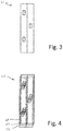
- the state-space is shown in Figure 3 and 4 .
- an extended state in space and time is considered as a state for the fully automated lane change.
- the computation problem is made tractable by considering a limited section of roadway. For example, 100 m both ahead and behind is considered as a suitable region for the state space.
- the sensed data is a snapshot in time captured repeatedly, as illustrated schematically in the frame stack 15 of Figure 2 , comprising at least two frames 16, 17, 18.
- each frame 26, 27, 28 of the frame stack 25 is provided to the sensory fusion processor 36 which outputs a simplified representation of the vehicular environment in the form of the semantic image 21.
- Figure 3 illustrates a single semantic image 21 corresponding to the rear data of Figure 1 .
- Figure 4 illustrates a stack 25 of semantic images 26, 27, 28 corresponding to the stacked data 16, 17, 18 of Figure 2 .
- the stacked original data 15 and corresponding stacked semantic data 25 are generated in real time at a rate 5 frames at 0.1 s, either from simulated data or from real data as the vehicle 10 is being driven on the roadway 9.
- the stacked sematic images exist in the extended state space.
- Each from of semantic data 21 consists of digital data with a discrete resolution in two dimensions.
- the cells, or grids, of the semantic data are in a rectangular array extending 80 elements in the transverse direction (W) and 200 elements in the longitudinal direction (D).
- W transverse direction
- D longitudinal direction
- the grids or cells are not shown in Figures 3 and 4 , but would be a grid overlaid the schematic representations.
- MDP Markov Decision Process
- Reinforcement learning 37 works particularly well where the control dynamics are spelt out implicitly. In this case, collision checking in the model is done implicitly. Hence the corner cases need not be hard-coded which reduces the chances of software bugs in a released product.
- Another advantage of this approach is that the system can readily be extended. This is because unlike control theoretic approaches, no model is assumed. Rather the underlying model is sought to be learned through efficient simulation of the data.
- a network based solution will, in general, be slower than a rule-based system (which typically would check some simple constraints and hence can run in order of micro-seconds), because the system uses semantic images to generate a yes/no decision on whether or not to implement a lane change, and is not concerned with calculating any lane change trajectories, it is fast enough for real-time lane change. This is ensured by making the underlying deep policy as a small network.
- the fully automated lane change algorithm with the underlying network has only 212 parameters (typical deep networks have several million parameters). This can run with 1000 Hz which is more than sufficient for making a fully automated lane change decision effectively in real time, for example in less than 0.1 s.
- the automated lane change system 90 is incorporated as part of the vehicular automated driving system 100 for driving automatically the ego vehicle 10 in the vehicular driving environment 1.
- the vehicle will, in general comprise also a steering system 101, an engine or motor 102 and a power train 103, which are linked by a data bus105 to the automated driving system 100, as well as a set of road going wheels linked to a braking system104.
- the automated lane change system 90 comprises a plurality of sensory inputs 91 each for receiving corresponding sensory data from the plurality of sensors 71, 72, 73.
- the sensory fusion processor 36 combines the sensory data, and a neural network (N) for generating a yes / no decision for initiating a lane change from the first to the second lanes 2, 3 of the roadway 9.
- the vehicular automated driving system 100 is configured, in use, to provide to the sensory inputs 91 the sensory data 8 from disparate sources, this data being representative of the vehicular driving environment 1 of the ego vehicle 10.
- the sensory data 8 is then combined in the sensory fusion processor 36 to generate the semantic image 21 of the sensed vehicular driving environment.
- the semantic image is a simplified static grid-like representation in two dimensions of the vehicular driving environment 1 at the time the sensory data was provided to the sensory inputs 105. The two dimensions extending along the roadway both ahead and behind (D) ego vehicle 10 and laterally across (W) the lanes 2,3.
- the sensory fusion processor 36 is used to repeatedly generate the semantic images 26, 27, 28, the semantic images providing a sequence of at least two of the static representations 16, 17, 18 of the vehicular driving environment 1 at corresponding times during which the ego vehicle 10 travels in the first lane 2 along the roadway 9.
- the semantic images are then provided to the neural network (N) of the automated lane change system 90, and the neural network then processes the sequence of grid-like representations to generate a yes/no decision for initiating a lane change of the ego vehicle 10 from the first lane 2 to the second lane 3.
- the vehicular automated driving system then acts on the decision being in the affirmative to calculate a trajectory 110 for the forthcoming lane change, and after the trajectory has been calculated, acts to control 101-105 the movement the vehicle 10 from the first lane 2 to the second lane 3 along the calculated trajectory 110.
- the above embodiments therefore provide a convenient and efficient system and method for automatically initiating a change of lane in an automated automotive vehicle, particularly in a SAE Level-4 vehicular automated driving system.
Priority Applications (3)
| Application Number | Priority Date | Filing Date | Title |
|---|---|---|---|
| EP18212102.0A EP3667556A1 (de) | 2018-12-12 | 2018-12-12 | Autonomer spurwechsel |
| CN201911255884.4A CN111301419A (zh) | 2018-12-12 | 2019-12-10 | 用于sae 4级自动化车道变更的基于强化学习的方法 |
| US16/712,376 US20200189597A1 (en) | 2018-12-12 | 2019-12-12 | Reinforcement learning based approach for sae level-4 automated lane change |
Applications Claiming Priority (1)
| Application Number | Priority Date | Filing Date | Title |
|---|---|---|---|
| EP18212102.0A EP3667556A1 (de) | 2018-12-12 | 2018-12-12 | Autonomer spurwechsel |
Publications (1)
| Publication Number | Publication Date |
|---|---|
| EP3667556A1 true EP3667556A1 (de) | 2020-06-17 |
Family
ID=64901315
Family Applications (1)
| Application Number | Title | Priority Date | Filing Date |
|---|---|---|---|
| EP18212102.0A Withdrawn EP3667556A1 (de) | 2018-12-12 | 2018-12-12 | Autonomer spurwechsel |
Country Status (3)
| Country | Link |
|---|---|
| US (1) | US20200189597A1 (de) |
| EP (1) | EP3667556A1 (de) |
| CN (1) | CN111301419A (de) |
Cited By (4)
| Publication number | Priority date | Publication date | Assignee | Title |
|---|---|---|---|---|
| CN112835362A (zh) * | 2020-12-29 | 2021-05-25 | 际络科技(上海)有限公司 | 一种自动变道规划方法及装置、电子设备和存储介质 |
| US11080602B1 (en) | 2020-06-27 | 2021-08-03 | Sas Institute Inc. | Universal attention-based reinforcement learning model for control systems |
| CN113911129A (zh) * | 2021-11-23 | 2022-01-11 | 吉林大学 | 一种基于驾驶行为生成机制的交通车意图识别方法 |
| GB2598758A (en) * | 2020-09-10 | 2022-03-16 | Toshiba Kk | Task performing agent systems and methods |
Families Citing this family (8)
| Publication number | Priority date | Publication date | Assignee | Title |
|---|---|---|---|---|
| CN109606384B (zh) * | 2018-12-29 | 2021-04-20 | 百度在线网络技术(北京)有限公司 | 车辆控制方法、装置、设备和存储介质 |
| CN111845741B (zh) * | 2020-06-28 | 2021-08-03 | 江苏大学 | 一种基于分层强化学习的自动驾驶决策控制方法及系统 |
| DE102020121150A1 (de) * | 2020-08-11 | 2022-02-17 | Bayerische Motoren Werke Aktiengesellschaft | Trainieren eines Reinforcement Learning Agenten zur Steuerung eines autonomen Systems |
| CN114074680B (zh) * | 2020-08-11 | 2023-08-22 | 湖南大学 | 基于深度强化学习的车辆换道行为决策方法及系统 |
| CN112406867B (zh) * | 2020-11-19 | 2021-12-28 | 清华大学 | 基于强化学习和避让策略的应急车辆混合换道决策方法 |
| CN112498354B (zh) * | 2020-12-25 | 2021-11-12 | 郑州轻工业大学 | 考虑个性化驾驶体验的多时间尺度自学习变道方法 |
| CN112721929B (zh) * | 2021-01-11 | 2022-11-22 | 成都语动未来科技有限公司 | 一种基于搜索技术的自动驾驶车辆变道行为决策方法 |
| CN113844448A (zh) * | 2021-09-18 | 2021-12-28 | 广东松科智能科技有限公司 | 基于深度强化学习的车道保持方法 |
Citations (1)
| Publication number | Priority date | Publication date | Assignee | Title |
|---|---|---|---|---|
| WO2017120336A2 (en) * | 2016-01-05 | 2017-07-13 | Mobileye Vision Technologies Ltd. | Trained navigational system with imposed constraints |
-
2018
- 2018-12-12 EP EP18212102.0A patent/EP3667556A1/de not_active Withdrawn
-
2019
- 2019-12-10 CN CN201911255884.4A patent/CN111301419A/zh active Pending
- 2019-12-12 US US16/712,376 patent/US20200189597A1/en not_active Abandoned
Patent Citations (1)
| Publication number | Priority date | Publication date | Assignee | Title |
|---|---|---|---|---|
| WO2017120336A2 (en) * | 2016-01-05 | 2017-07-13 | Mobileye Vision Technologies Ltd. | Trained navigational system with imposed constraints |
Non-Patent Citations (2)
| Title |
|---|
| ANONYMOUS: "Advanced Planning for Autonomous Vehicles Using Reinforcement Learning and Deep Inverse Reinforcement Learning", 1 October 2018 (2018-10-01), XP055603176, Retrieved from the Internet <URL:https://web.archive.org/web/20181001053144/http://dcsl.gatech.edu/research/autonomous-vehicle-learning.html> [retrieved on 20190708] * |
| WANG PIN ET AL: "A Reinforcement Learning Based Approach for Automated Lane Change Maneuvers", 2018 IEEE INTELLIGENT VEHICLES SYMPOSIUM (IV), IEEE, 26 June 2018 (2018-06-26), pages 1379 - 1384, XP033423455, DOI: 10.1109/IVS.2018.8500556 * |
Cited By (6)
| Publication number | Priority date | Publication date | Assignee | Title |
|---|---|---|---|---|
| US11080602B1 (en) | 2020-06-27 | 2021-08-03 | Sas Institute Inc. | Universal attention-based reinforcement learning model for control systems |
| GB2598758A (en) * | 2020-09-10 | 2022-03-16 | Toshiba Kk | Task performing agent systems and methods |
| GB2598758B (en) * | 2020-09-10 | 2023-03-29 | Toshiba Kk | Task performing agent systems and methods |
| CN112835362A (zh) * | 2020-12-29 | 2021-05-25 | 际络科技(上海)有限公司 | 一种自动变道规划方法及装置、电子设备和存储介质 |
| CN113911129A (zh) * | 2021-11-23 | 2022-01-11 | 吉林大学 | 一种基于驾驶行为生成机制的交通车意图识别方法 |
| CN113911129B (zh) * | 2021-11-23 | 2023-02-24 | 吉林大学 | 一种基于驾驶行为生成机制的交通车意图识别方法 |
Also Published As
| Publication number | Publication date |
|---|---|
| US20200189597A1 (en) | 2020-06-18 |
| CN111301419A (zh) | 2020-06-19 |
Similar Documents
| Publication | Publication Date | Title |
|---|---|---|
| EP3667556A1 (de) | Autonomer spurwechsel | |
| US10627823B1 (en) | Method and device for performing multiple agent sensor fusion in cooperative driving based on reinforcement learning | |
| CN110362077B (zh) | 无人驾驶车辆紧急避险决策系统、方法及介质 | |
| EP1332910B1 (de) | Verfahren und System zur Verbesserung der Fahrerunterstützung | |
| CN113291308B (zh) | 一种考虑驾驶行为特性的车辆自学习换道决策系统及方法 | |
| WO2020180881A1 (en) | State machine for traversing junctions | |
| US11498574B2 (en) | Learning device, learning method, and storage medium | |
| US20200238980A1 (en) | Vehicle control device | |
| EP3715204A1 (de) | Fahrzeugsteuerungsvorrichtung | |
| JP7172287B2 (ja) | 自動運転システム | |
| US20200353918A1 (en) | Vehicle control device | |
| CN112046484B (zh) | 一种基于q学习的车辆变道超车路径规划方法 | |
| JP7048455B2 (ja) | 学習装置、シミュレーションシステム、学習方法、およびプログラム | |
| CN113247023B (zh) | 一种行驶规划方法、装置、计算机设备及存储介质 | |
| EP4119412A1 (de) | Verfahren und vorrichtung zur fahrzeugbasierten datenverarbeitung, computer und speichermedium | |
| CN114906164A (zh) | 用于自主驾驶的轨迹验证 | |
| EP3690845A1 (de) | Verfahren zur bereitstellung einer autonomen fahrdienstplattform zur unterstützung des autonomen fahrens von fahrzeugen unter verwendung von kompetitiver berechnung und informationsfusion und server damit | |
| EP4092633A1 (de) | Verfahren und vorrichtung zur spurwechselvorhersage eines zielfahrzeugs | |
| Weisswange et al. | Intelligent traffic flow assist: Optimized highway driving using conditional behavior prediction | |
| CN112673230A (zh) | 行驶辅助方法及行驶辅助装置 | |
| CN113160550B (zh) | 涉及交叉路口的自动驾驶场景的传感器覆盖范围分析 | |
| Chandru et al. | Motion planning for autonomous lane change manoeuvre with abort ability | |
| KR20220108823A (ko) | 차량의 궤적을 예측하는 시스템 및 방법 | |
| CN113465618A (zh) | 交通工具的目标导向的导航系统及相关方法 | |
| CN113460079A (zh) | 车辆控制装置、车辆控制方法及存储介质 |
Legal Events
| Date | Code | Title | Description |
|---|---|---|---|
| PUAI | Public reference made under article 153(3) epc to a published international application that has entered the european phase |
Free format text: ORIGINAL CODE: 0009012 |
|
| STAA | Information on the status of an ep patent application or granted ep patent |
Free format text: STATUS: THE APPLICATION HAS BEEN PUBLISHED |
|
| AK | Designated contracting states |
Kind code of ref document: A1 Designated state(s): AL AT BE BG CH CY CZ DE DK EE ES FI FR GB GR HR HU IE IS IT LI LT LU LV MC MK MT NL NO PL PT RO RS SE SI SK SM TR |
|
| AX | Request for extension of the european patent |
Extension state: BA ME |
|
| STAA | Information on the status of an ep patent application or granted ep patent |
Free format text: STATUS: THE APPLICATION IS DEEMED TO BE WITHDRAWN |
|
| 18D | Application deemed to be withdrawn |
Effective date: 20201218 |