EP3667355A1 - Method for radio direction finding, direction finding system as well as platform - Google Patents
Method for radio direction finding, direction finding system as well as platform Download PDFInfo
- Publication number
- EP3667355A1 EP3667355A1 EP18211860.4A EP18211860A EP3667355A1 EP 3667355 A1 EP3667355 A1 EP 3667355A1 EP 18211860 A EP18211860 A EP 18211860A EP 3667355 A1 EP3667355 A1 EP 3667355A1
- Authority
- EP
- European Patent Office
- Prior art keywords
- magnetic
- direction finding
- platform
- finding system
- correction table
- Prior art date
- Legal status (The legal status is an assumption and is not a legal conclusion. Google has not performed a legal analysis and makes no representation as to the accuracy of the status listed.)
- Pending
Links
Images
Classifications
-
- G—PHYSICS
- G01—MEASURING; TESTING
- G01S—RADIO DIRECTION-FINDING; RADIO NAVIGATION; DETERMINING DISTANCE OR VELOCITY BY USE OF RADIO WAVES; LOCATING OR PRESENCE-DETECTING BY USE OF THE REFLECTION OR RERADIATION OF RADIO WAVES; ANALOGOUS ARRANGEMENTS USING OTHER WAVES
- G01S3/00—Direction-finders for determining the direction from which infrasonic, sonic, ultrasonic or electromagnetic waves, or particle emission, not having a directional significance, are being received
- G01S3/02—Direction-finders for determining the direction from which infrasonic, sonic, ultrasonic or electromagnetic waves, or particle emission, not having a directional significance, are being received using radio waves
- G01S3/04—Details
- G01S3/10—Means for reducing or compensating for quadrantal, site, or like errors
-
- G—PHYSICS
- G01—MEASURING; TESTING
- G01C—MEASURING DISTANCES, LEVELS OR BEARINGS; SURVEYING; NAVIGATION; GYROSCOPIC INSTRUMENTS; PHOTOGRAMMETRY OR VIDEOGRAMMETRY
- G01C21/00—Navigation; Navigational instruments not provided for in groups G01C1/00 - G01C19/00
- G01C21/20—Instruments for performing navigational calculations
-
- G—PHYSICS
- G01—MEASURING; TESTING
- G01S—RADIO DIRECTION-FINDING; RADIO NAVIGATION; DETERMINING DISTANCE OR VELOCITY BY USE OF RADIO WAVES; LOCATING OR PRESENCE-DETECTING BY USE OF THE REFLECTION OR RERADIATION OF RADIO WAVES; ANALOGOUS ARRANGEMENTS USING OTHER WAVES
- G01S3/00—Direction-finders for determining the direction from which infrasonic, sonic, ultrasonic or electromagnetic waves, or particle emission, not having a directional significance, are being received
- G01S3/02—Direction-finders for determining the direction from which infrasonic, sonic, ultrasonic or electromagnetic waves, or particle emission, not having a directional significance, are being received using radio waves
- G01S3/023—Monitoring or calibrating
-
- G—PHYSICS
- G01—MEASURING; TESTING
- G01S—RADIO DIRECTION-FINDING; RADIO NAVIGATION; DETERMINING DISTANCE OR VELOCITY BY USE OF RADIO WAVES; LOCATING OR PRESENCE-DETECTING BY USE OF THE REFLECTION OR RERADIATION OF RADIO WAVES; ANALOGOUS ARRANGEMENTS USING OTHER WAVES
- G01S3/00—Direction-finders for determining the direction from which infrasonic, sonic, ultrasonic or electromagnetic waves, or particle emission, not having a directional significance, are being received
- G01S3/02—Direction-finders for determining the direction from which infrasonic, sonic, ultrasonic or electromagnetic waves, or particle emission, not having a directional significance, are being received using radio waves
- G01S3/04—Details
- G01S3/046—Displays or indicators
-
- G—PHYSICS
- G01—MEASURING; TESTING
- G01S—RADIO DIRECTION-FINDING; RADIO NAVIGATION; DETERMINING DISTANCE OR VELOCITY BY USE OF RADIO WAVES; LOCATING OR PRESENCE-DETECTING BY USE OF THE REFLECTION OR RERADIATION OF RADIO WAVES; ANALOGOUS ARRANGEMENTS USING OTHER WAVES
- G01S3/00—Direction-finders for determining the direction from which infrasonic, sonic, ultrasonic or electromagnetic waves, or particle emission, not having a directional significance, are being received
- G01S3/02—Direction-finders for determining the direction from which infrasonic, sonic, ultrasonic or electromagnetic waves, or particle emission, not having a directional significance, are being received using radio waves
- G01S3/14—Systems for determining direction or deviation from predetermined direction
- G01S3/46—Systems for determining direction or deviation from predetermined direction using antennas spaced apart and measuring phase or time difference between signals therefrom, i.e. path-difference systems
Definitions
- the invention relates to a method for radio direction finding using a direction finding system for a platform, a direction finding system for a platform as well as a platform comprising a direction finding system.
- a bearing to an emitter is determined using an antenna. Further, a magnetic sensor is used to determine the absolute bearing.
- the known methods have been proven to be imprecise, especially when direction finding systems are used on different platforms.
- the method comprises the following steps:
- the step of correcting and/or the step of determining is preferably performed by the control unit.
- the vehicle may be an aquatic vehicle, like a ship, a land-based vehicle, like a car or truck, or an airborne vehicle, like a plane.
- the magnetic measurement value is corrected by the control unit using a predetermined magnetic correction table having magnetic correction values, particularly wherein the magnetic correction values are based on at least magnetic deviations of the magnetic field surrounding the direction finding system caused by the platform itself and/or by alignment errors of the magnetic field sensor mounted the platform. This way, the magnetic measurement value is corrected individually.
- the magnetic correction values are suitable to be used by the control unit to correct at least measurement errors or bearing errors.
- the method comprises the following further steps:
- the bearing is determined with an even higher accuracy.
- the received signal is corrected by the control unit using a predetermined azimuth correction table having azimuth correction values, particularly wherein the azimuth correction values are based on at least the influence of the platform on the measurement of the antenna allowing individual correction of the received signal.
- the azimuth correction values are suitable to be used by the control unit to correct at least measurement errors or bearing errors.
- the azimuth correction values may depend on the frequency of the at least one radio frequency signal and/or the bearing determined using the received signal, further improving accuracy.
- the magnetic correction table and/or the azimuth correction table has been determined prior to operation of the platform, in particular the magnetic correction table and/or the azimuth correction table has been determined for each platform individually.
- the magnetic correction table and/or azimuth correction table may be determined individually for each platform, even if platforms are of the same make and model.
- the method having at least one of the following further steps allowing further action and analysis of the bearing:
- the visualization may be a map, in which the precise bearing and/or the estimated location of the emitter is marked.
- a direction finding system for a platform in particular a vehicle, comprises at least one antenna, at least one magnetic field sensor and a control unit electrically connected to the at least one magnetic field sensor and the at least one antenna, wherein the control unit is configured to perform a method as described above.
- the magnetic field sensor is a compass and/or the antenna is a directional antenna allowing precise measurements.
- the direction finding system comprises a display for visualizing the precise bearing, a speaker for generating an acoustic output representing the precise bearing and/or a printer for printing the precise bearing so that information about the bearing is easily available.
- the control unit may comprise a magnetic correction table and/or an azimuth correction table for simple and reliable correction of the measured values.
- a platform in particular a vehicle is provided comprising a direction finding system as discussed above.
- the predetermined magnetic correction table and/or the azimuth correction table are specific to the platform, in particular the magnetic correction table and/or the azimuth correction table are specific to the specific platform individually allowing very individual and precise correction.
- the word "specific” is used in the sense that the correction table has been determined prior to operation of the platform of the direction finding system, in particular the correction table has been determined for each platform individually.
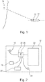
- Figure 1 shows a platform 10 with a direction finding system 12.
- the platform 10 is an aquatic vehicle, like a ship.
- the platform 10 may also be a land-based vehicle, like a car or a truck, or an airborne vehicle like a plane.
- the platform 10 is navigating in the sea and an emitter 14, for example a radio beacon station, is located at the shore.
- an emitter 14 for example a radio beacon station
- the emitter 14 emits at least one radio frequency signal - for example with a frequency of 1 GHz - that can be used for location finding of vehicles.
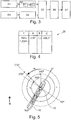
- Figure 2 shows the direction finding system 12 in detail.
- the direction finding system 12 comprises an antenna 16, for example a directional antenna, a magnetic field sensor 18, for example a compass, a control unit 20, a display 22, a speaker 24 and a printer 25.
- the antenna 16, the magnetic field sensor 18, the display 22, the speaker 24 and the printer 25 are electrically and operatively connected to the control unit 20.
- control unit 20 controls the antenna 16, the magnetic field sensor 18, the display 22, the speaker 24 and/or the printer 25.
- the control unit 20 comprises a memory 26, in which correction tables may be stored, for example a magnetic correction table and an azimuth correction table 28 ( Figure 4 ).
- the control unit 20 is configured to determine the bearing of the emitter 14 and/or the location of the platform 10 based on bearings form multiple emitters 14.
- the control unit 20 may perform the method for radio direction finding shown as a flow chart in Figure 3 .
- a first step S1 the radio frequency signal of the emitter 14 is received by the antenna 16 and transmitted to the control unit 20 as a received signal.
- control unit 20 corrects the received signal and thus obtains a corrected received signal.
- the control unit uses, for example, the azimuth correction table 28 stored in the memory 26.
- the azimuth correction table 28 is, for example, a multidimensional array of azimuth correction values based on one or more parameters. A simplified illustration of the azimuth correction table 28 is shown in Figure 4 .
- the azimuth correction table 28 with its azimuth correction values is determined prior to operation of the platform 10, for example by determining the bearing of emitters from a known direction. The determined bearing based on the received signal does not correspond to the actual bearing of the emitter because the platform 10 disturbs the measurement of the antenna 16.
- the azimuth correction table 28 may be determined prior to operation for one type of platform 10, in this embodiment for a specific make and model of the ship or platform in general. However, to achieve even better results, the azimuth correction table 28 may be determined for each specific platform 10 individually. For example, even though different platforms 10 may be of the same series, i.e. are of the same make and model, each of the platforms 10 has its specific unique azimuth correction table 28.
- the azimuth correction table could also be an azimuth correction function for calculating the azimuth correction value or the corrected signal.
- the azimuth correction values are based on these influences and may then be used to eliminate these deviations from the received signal of the antenna 16.
- control unit 20 is able to determine the corrected signal, for example as follows.
- step S2.1 the control unit 20 determines a rough bearing of the emitter 14 based on the received signal only, for example as 210°.
- the control unit 20 looks up the correction value for the determined rough bearing and the frequency f of the radio frequency signal, which is 1 GHz in the shown example.
- the azimuth correction value in this case is -1.3 so that the corrected signal is a corrected bearing of 208,7°.
- This corrected bearing is, however, not the final and precise bearing to be determined.
- the magnetic field at the direction finding system 12 is determined by the magnetic field sensor 18.
- the measurement value of the magnetic field is transmitted to the control unit 20 (step S3).
- control unit 20 corrects the magnetic measurement value to obtain a corrected magnetic measurement value.
- the magnetic measurement value and the corrected measurement value may be bearings with respect to the magnetic North.
- the corrected magnetic measurement value is determined by the control unit 20 using the magnetic correction table stored in the memory 26.
- the magnetic correction table comprises magnetic correction values that may be based on the measured value, the temperature or other parameters.
- the magnetic correction table may also be a two-dimensional table or multidimensional array of correction values.
- the magnetic correction table could also be a magnetic correction function for calculating the magnetic correction value or the corrected magnetic measurement value.
- the magnetic correction table with its magnetic correction values is determined prior to operation of the platform 10, for example by determining the magnetic measurement values in a known magnetic field.
- the magnetic field measured by the magnetic field sensor 18 does not correspond to the actual magnetic field surrounding the platform 10 because the platform 10 itself creates deviations in the magnetic field surrounding the direction finding system 12 and the magnetic field sensor 18 may be misaligned with respect to the longitudinal axis of the platform 10.
- the magnetic correction values are based on these measured deviations and may then be used to eliminate these deviations from the magnetic measurement values of the magnetic field sensor 18.
- the magnetic correction table may be determined for one type of platform 10, in this embodiment for a specific make and model of the ship. However, to achieve even better results, the magnetic correction table may be determined for each specific platform 10 individually. For example, even though different platforms 10 may be of the same series, i. e. are of the same make and model, each of the platforms 10 has its specific unique magnetic correction table.
- control unit 20 obtains corrected magnetic measurement values for further use (step S4).
- step S5 the control unit 20 determines the precise bearing of the emitter 14 using the corrected magnetic measurement value and the corrected received signal - for example the corrected bearing. This may be done using a per se known method for determining bearings, as shown in Figure 5 .
- the corrected magnetic measurement value c e. g. the bearing with respect to magnetic North
- the corrected signal b e. g. the corrected bearing of the emitter 14 is added yielding the precise bearing w (shown as -w in Figure 5 ).
- w 360° - c + b.
- the precise bearing of the emitter 14 can be determined, and the precise bearing is also based on the received signal and the magnetic measurement value, even though they have been corrected.
- the precise bearing is visualized on the display 22, for example using a GUI, and/or by reproducing a map, in which the precise bearing and/or even the estimated location of the emitter 14 is marked.
- an acoustic signal representing the precise bearing may be generated by the speaker 24 controlled by the control unit 20.
- step S6 or in a further step the precise bearing may also be printed, by the printer 25 or stored in the control unit 20 or elsewhere.
- the correction of the received signal and the correction of the magnetic measurement value may be interdependent from one another.
- the azimuth correction table 28 may have azimuth correction values based on the measured or corrected magnetic measurement values or vice versa.
Landscapes
- Engineering & Computer Science (AREA)
- Radar, Positioning & Navigation (AREA)
- Remote Sensing (AREA)
- Physics & Mathematics (AREA)
- General Physics & Mathematics (AREA)
- Automation & Control Theory (AREA)
- Navigation (AREA)
- Measuring Magnetic Variables (AREA)
Abstract
Description
- The invention relates to a method for radio direction finding using a direction finding system for a platform, a direction finding system for a platform as well as a platform comprising a direction finding system.
- In direction finding systems and in methods for radio direction finding, a bearing to an emitter is determined using an antenna. Further, a magnetic sensor is used to determine the absolute bearing. However, the known methods have been proven to be imprecise, especially when direction finding systems are used on different platforms.
- Thus, it is the object of the invention to provide a method for radio direction finding, a direction finding system and a platform, which provide very precise bearings.
- For this purpose, a method is provided for radio direction finding using a direction finding system for a platform, in particular a vehicle, having at least one antenna, at least one magnetic field sensor and a control unit electrically connected to the at least one magnetic field sensor and the at least one antenna. The method comprises the following steps:
- a) receiving at least one radio frequency signal of at least one emitter via the antenna by the control unit obtaining a received signal,
- b) receiving a magnetic measurement value of the magnetic field at the direction finding system via the magnetic field sensor by the control unit,
- c) correcting the magnetic measurement value obtaining a corrected magnetic measurement value, and
- d) determining the precise bearing of the emitter based on the received signal and the corrected magnetic measurement value.
- By correcting the magnetic measurement value, the accuracy of the bearing can be improved drastically.
- The step of correcting and/or the step of determining is preferably performed by the control unit.
- The vehicle may be an aquatic vehicle, like a ship, a land-based vehicle, like a car or truck, or an airborne vehicle, like a plane.
- In an embodiment of the invention, the magnetic measurement value is corrected by the control unit using a predetermined magnetic correction table having magnetic correction values, particularly wherein the magnetic correction values are based on at least magnetic deviations of the magnetic field surrounding the direction finding system caused by the platform itself and/or by alignment errors of the magnetic field sensor mounted the platform. This way, the magnetic measurement value is corrected individually.
- The magnetic correction values are suitable to be used by the control unit to correct at least measurement errors or bearing errors.
- In an aspect of the invention, the method comprises the following further steps:
- a) correcting the received signal obtaining a corrected signal, and
- b) determining the bearing of the emitter based on the corrected received signal and the corrected magnetic measurement value.
- By correcting the received signal, the bearing is determined with an even higher accuracy.
- For example, the received signal is corrected by the control unit using a predetermined azimuth correction table having azimuth correction values, particularly wherein the azimuth correction values are based on at least the influence of the platform on the measurement of the antenna allowing individual correction of the received signal.
- The azimuth correction values are suitable to be used by the control unit to correct at least measurement errors or bearing errors.
- The azimuth correction values may depend on the frequency of the at least one radio frequency signal and/or the bearing determined using the received signal, further improving accuracy.
- For determining the correction values accurately, the magnetic correction table and/or the azimuth correction table has been determined prior to operation of the platform, in particular the magnetic correction table and/or the azimuth correction table has been determined for each platform individually.
- The magnetic correction table and/or azimuth correction table may be determined individually for each platform, even if platforms are of the same make and model.
- In another embodiment, the method having at least one of the following further steps allowing further action and analysis of the bearing:
- a) visualizing the precise bearing on a display of the direction finding system, in particular using a GUI and/or a map,
- b) storing the precise bearing,
- c) further processing the precise bearing,
- d) printing the precise bearing, and
- e) generating an acoustic output using a speaker of the direction finding system representing the precise bearing.
- The visualization may be a map, in which the precise bearing and/or the estimated location of the emitter is marked.
- Further, for above object, a direction finding system for a platform, in particular a vehicle, comprises at least one antenna, at least one magnetic field sensor and a control unit electrically connected to the at least one magnetic field sensor and the at least one antenna, wherein the control unit is configured to perform a method as described above.
- Preferably, the magnetic field sensor is a compass and/or the antenna is a directional antenna allowing precise measurements.
- In an embodiment, the direction finding system comprises a display for visualizing the precise bearing, a speaker for generating an acoustic output representing the precise bearing and/or a printer for printing the precise bearing so that information about the bearing is easily available.
- The control unit may comprise a magnetic correction table and/or an azimuth correction table for simple and reliable correction of the measured values.
- For above object, further a platform, in particular a vehicle is provided comprising a direction finding system as discussed above.
- For example, the predetermined magnetic correction table and/or the azimuth correction table are specific to the platform, in particular the magnetic correction table and/or the azimuth correction table are specific to the specific platform individually allowing very individual and precise correction.
- The word "specific" is used in the sense that the correction table has been determined prior to operation of the platform of the direction finding system, in particular the correction table has been determined for each platform individually.
- Of course, the features and advantages discussed in the context of the invention also apply to the direction finding system and the platform and vice versa.
- Further features and advantages will be apparent from the following description as well as the accompanying drawings, to which reference is made. In the drawings:
-
Figure 1 shows a platform according to the invention with a direction finding system according to the invention while using the method according to the invention, -
Figure 2 shows the direction finding system according toFigure 1 in more detail, -
Figure 3 shows a flow chart of a method according to the invention, -
Figure 4 shows an azimuth correction table for use in the method according toFigure 3 , and -
Figure 5 shows a platform with a direction finding system in a different scenario. -
Figure 1 shows aplatform 10 with a direction findingsystem 12. - In the shown embodiment, the
platform 10 is an aquatic vehicle, like a ship. - The
platform 10 may also be a land-based vehicle, like a car or a truck, or an airborne vehicle like a plane. - In the shown scenario, the
platform 10 is navigating in the sea and anemitter 14, for example a radio beacon station, is located at the shore. - The
emitter 14 emits at least one radio frequency signal - for example with a frequency of 1 GHz - that can be used for location finding of vehicles. -
Figure 2 shows thedirection finding system 12 in detail. - The direction finding
system 12 comprises anantenna 16, for example a directional antenna, amagnetic field sensor 18, for example a compass, acontrol unit 20, adisplay 22, aspeaker 24 and aprinter 25. - The
antenna 16, themagnetic field sensor 18, thedisplay 22, thespeaker 24 and theprinter 25 are electrically and operatively connected to thecontrol unit 20. - Thus, the
control unit 20 controls theantenna 16, themagnetic field sensor 18, thedisplay 22, thespeaker 24 and/or theprinter 25. - The
control unit 20 comprises amemory 26, in which correction tables may be stored, for example a magnetic correction table and an azimuth correction table 28 (Figure 4 ). - The
control unit 20 is configured to determine the bearing of theemitter 14 and/or the location of theplatform 10 based on bearings formmultiple emitters 14. - The
control unit 20 may perform the method for radio direction finding shown as a flow chart inFigure 3 . - In a first step S1 the radio frequency signal of the
emitter 14 is received by theantenna 16 and transmitted to thecontrol unit 20 as a received signal. - In the next step S2 the
control unit 20 corrects the received signal and thus obtains a corrected received signal. - The control unit uses, for example, the azimuth correction table 28 stored in the
memory 26. - The azimuth correction table 28 is, for example, a multidimensional array of azimuth correction values based on one or more parameters. A simplified illustration of the azimuth correction table 28 is shown in
Figure 4 . - In the azimuth correction table 28 for given frequencies f and determined bearings (column A) an azimuth correction value (column B) is given. Also, in column C the corrected value for the bearing is stored.
- The azimuth correction table 28 with its azimuth correction values is determined prior to operation of the
platform 10, for example by determining the bearing of emitters from a known direction. The determined bearing based on the received signal does not correspond to the actual bearing of the emitter because theplatform 10 disturbs the measurement of theantenna 16. - The azimuth correction table 28 may be determined prior to operation for one type of
platform 10, in this embodiment for a specific make and model of the ship or platform in general. However, to achieve even better results, the azimuth correction table 28 may be determined for eachspecific platform 10 individually. For example, even thoughdifferent platforms 10 may be of the same series, i.e. are of the same make and model, each of theplatforms 10 has its specific unique azimuth correction table 28. - Of course, the azimuth correction table could also be an azimuth correction function for calculating the azimuth correction value or the corrected signal.
- The azimuth correction values are based on these influences and may then be used to eliminate these deviations from the received signal of the
antenna 16. - With this kind of information, especially with the azimuth correction values, the
control unit 20 is able to determine the corrected signal, for example as follows. - In step S2.1, the
control unit 20 determines a rough bearing of theemitter 14 based on the received signal only, for example as 210°. - In the next step S2.2, the
control unit 20 looks up the correction value for the determined rough bearing and the frequency f of the radio frequency signal, which is 1 GHz in the shown example. - As can be seen in
Figure 4 , the azimuth correction value in this case is -1.3 so that the corrected signal is a corrected bearing of 208,7°. - This corrected bearing is, however, not the final and precise bearing to be determined.
- Simultaneously or subsequently, the magnetic field at the
direction finding system 12 is determined by themagnetic field sensor 18. - The measurement value of the magnetic field, called magnetic measurement value in the following, is transmitted to the control unit 20 (step S3).
- Subsequently, the
control unit 20 corrects the magnetic measurement value to obtain a corrected magnetic measurement value. - The magnetic measurement value and the corrected measurement value may be bearings with respect to the magnetic North.
- The corrected magnetic measurement value is determined by the
control unit 20 using the magnetic correction table stored in thememory 26. - Just like the azimuth correction table 28, the magnetic correction table comprises magnetic correction values that may be based on the measured value, the temperature or other parameters.
- The magnetic correction table may also be a two-dimensional table or multidimensional array of correction values.
- Of course, the magnetic correction table could also be a magnetic correction function for calculating the magnetic correction value or the corrected magnetic measurement value.
- The magnetic correction table with its magnetic correction values is determined prior to operation of the
platform 10, for example by determining the magnetic measurement values in a known magnetic field. The magnetic field measured by themagnetic field sensor 18 does not correspond to the actual magnetic field surrounding theplatform 10 because theplatform 10 itself creates deviations in the magnetic field surrounding thedirection finding system 12 and themagnetic field sensor 18 may be misaligned with respect to the longitudinal axis of theplatform 10. - The magnetic correction values are based on these measured deviations and may then be used to eliminate these deviations from the magnetic measurement values of the
magnetic field sensor 18. - The magnetic correction table may be determined for one type of
platform 10, in this embodiment for a specific make and model of the ship. However, to achieve even better results, the magnetic correction table may be determined for eachspecific platform 10 individually. For example, even thoughdifferent platforms 10 may be of the same series, i. e. are of the same make and model, each of theplatforms 10 has its specific unique magnetic correction table. - By applying the magnetic correction values to the magnetic measurement values, the
control unit 20 obtains corrected magnetic measurement values for further use (step S4). - In the next step, step S5, the
control unit 20 determines the precise bearing of theemitter 14 using the corrected magnetic measurement value and the corrected received signal - for example the corrected bearing. This may be done using a per se known method for determining bearings, as shown inFigure 5 . - From 360°, the corrected magnetic measurement value c, e. g. the bearing with respect to magnetic North, is subtracted and the corrected signal b, e. g. the corrected bearing of the
emitter 14 is added yielding the precise bearing w (shown as -w inFigure 5 ). Mathematically speaking: w = 360° - c + b. - Thus, the precise bearing of the
emitter 14 can be determined, and the precise bearing is also based on the received signal and the magnetic measurement value, even though they have been corrected. - In the next step S6, the precise bearing is visualized on the
display 22, for example using a GUI, and/or by reproducing a map, in which the precise bearing and/or even the estimated location of theemitter 14 is marked. - In the same step S6, an acoustic signal representing the precise bearing may be generated by the
speaker 24 controlled by thecontrol unit 20. - In step S6 or in a further step, the precise bearing may also be printed, by the
printer 25 or stored in thecontrol unit 20 or elsewhere. - It is also possible that in a further step S7, the precise bearing is processed further.
- It is of course possible that the correction of the received signal and the correction of the magnetic measurement value may be interdependent from one another. For example, the azimuth correction table 28 may have azimuth correction values based on the measured or corrected magnetic measurement values or vice versa.
Claims (15)
- Method for radio direction finding using a direction finding system (12) for a platform (10), in particular a vehicle, having at least one antenna (16), at least one magnetic field sensor (18) and a control unit (20) electrically connected to the at least one magnetic field sensor (18) and the at least one antenna (16), wherein the method comprises the following steps:a) receiving at least one radio frequency signal of at least one emitter (14) via the antenna (16) by the control unit (20) obtaining a received signal,b) receiving a magnetic measurement value of the magnetic field at the direction finding system (12) via the magnetic field sensor (18) by the control unit (20),c) correcting the magnetic measurement value obtaining a corrected magnetic measurement value, andd) determining the precise bearing of the emitter (14) based on the received signal and the corrected magnetic measurement value.
- Method according to claim 1, characterized in that the magnetic measurement value is corrected by the control unit (20) using a predetermined magnetic correction table having magnetic correction values, particularly wherein the magnetic correction values are based on at least magnetic deviations of the magnetic field surrounding the direction finding system (12) caused by the platform (10) itself and/or by alignment errors of the magnetic field sensor (18) mounted the platform (12).
- Method according to claim 1 or 2, characterized in that the method comprises the following further steps:a) correcting the received signal obtaining a corrected signal, andb) determining the bearing of the emitter (14) based on the corrected received signal and the corrected magnetic measurement value.
- Method according to any one of the preceding claims, characterized in that the received signal is corrected by the control unit (20) using a predetermined azimuth correction table (28) having azimuth correction values, particularly wherein the azimuth correction values are based on at least the influence of the platform (10) on the measurement of the antenna (16).
- Method according to claim 4, characterized in that the azimuth correction values depend on the frequency of the at least one radio frequency signal and/or the bearing determined using the received signal.
- Method according to any one of the claims 2 to 5, characterized in that the magnetic correction table and/or the azimuth correction table (28) has been determined prior to operation of the platform (10), in particular the magnetic correction table and/or the azimuth correction table (28) has been determined for each platform (10) individually.
- Method according to any one of the preceding claims, characterized in that the method having at least one of the following further steps:a) visualizing the precise bearing on a display (22) of the direction finding system (12), in particular using a GUI and/or a map,b) storing the precise bearing,c) further processing the precise bearing,d) printing the precise bearing, ande) generating an acoustic output using a speaker (24) of the direction finding system representing the precise bearing.
- Direction finding system for a platform (10), in particular a vehicle, comprising at least one antenna (16), at least one magnetic field sensor (18) and a control unit (20) electrically connected to the at least one magnetic field sensor (18) and the at least one antenna (16), wherein the control unit (20) is configured to perform a method according to any one of the preceding claims.
- Direction finding system according to claim 8, characterized in that the magnetic field sensor (18) is a compass and/or wherein the antenna (16) is a directional antenna.
- Direction finding system according to claim 8 or 9, characterized in that the direction finding system (12) comprises a display (22) for visualizing the precise bearing, a speaker (24) for generating an acoustic output representing the precise bearing and/or a printer (25) for printing the precise bearing.
- Direction finding system according to any one of the claims 8 to 10, characterized in that the control unit (20) comprises a magnetic correction table and/or an azimuth correction table (28).
- Direction finding system according to claim 11, characterized in that the control unit (20) comprises an azimuth correction table (28) having azimuth correction values, particularly wherein the azimuth correction values are based on at least the influence of the platform (10) on the measurement of the antenna (16).
- Direction finding system according to claim 11 or 12, characterized in that the control unit comprises a magnetic correction table having magnetic correction values, particularly wherein the magnetic correction values are based on at least magnetic deviations of the magnetic field surrounding the direction finding system (12) caused by the platform (10) itself and/or by alignment errors of the magnetic field sensor (18) mounted the platform (12).
- Platform, in particular a vehicle, comprising a direction finding system (12) according to any one of the claims 9 to 13.
- Platform according to claim 14, characterized in that the predetermined magnetic correction table and/or the azimuth correction table (28) are specific to the platform (10), in particular the magnetic correction table and/or the azimuth correction table (28) are specific to the specific platform (10) individually.
Priority Applications (3)
| Application Number | Priority Date | Filing Date | Title |
|---|---|---|---|
| EP18211860.4A EP3667355A1 (en) | 2018-12-12 | 2018-12-12 | Method for radio direction finding, direction finding system as well as platform |
| CN201911081228.7A CN111307151A (en) | 2018-12-12 | 2019-11-07 | Method, direction finding system and platform for radio direction finding |
| US16/680,253 US11835637B2 (en) | 2018-12-12 | 2019-11-11 | Method for radio direction finding, direction finding system as well as platform |
Applications Claiming Priority (1)
| Application Number | Priority Date | Filing Date | Title |
|---|---|---|---|
| EP18211860.4A EP3667355A1 (en) | 2018-12-12 | 2018-12-12 | Method for radio direction finding, direction finding system as well as platform |
Publications (1)
| Publication Number | Publication Date |
|---|---|
| EP3667355A1 true EP3667355A1 (en) | 2020-06-17 |
Family
ID=64664979
Family Applications (1)
| Application Number | Title | Priority Date | Filing Date |
|---|---|---|---|
| EP18211860.4A Pending EP3667355A1 (en) | 2018-12-12 | 2018-12-12 | Method for radio direction finding, direction finding system as well as platform |
Country Status (3)
| Country | Link |
|---|---|
| US (1) | US11835637B2 (en) |
| EP (1) | EP3667355A1 (en) |
| CN (1) | CN111307151A (en) |
Citations (4)
| Publication number | Priority date | Publication date | Assignee | Title |
|---|---|---|---|---|
| GB1344547A (en) * | 1970-08-07 | 1974-01-23 | Licentia Gmbh | Arrangement for compensating direction finding errors of a twin path cathode ray tube direction finder |
| GB2007059A (en) * | 1977-10-27 | 1979-05-10 | Aubrey M C | Radio direction finder |
| JPS6280573A (en) * | 1985-10-03 | 1987-04-14 | Mitsubishi Heavy Ind Ltd | True bearing display type radio bearing measuring instrument |
| DE19704853C1 (en) * | 1997-02-10 | 1998-06-18 | Leica Ag | Correction parameter evaluation method for on-board vehicle navigation system |
Family Cites Families (9)
| Publication number | Priority date | Publication date | Assignee | Title |
|---|---|---|---|---|
| JP4434818B2 (en) * | 2004-03-31 | 2010-03-17 | 京セラ株式会社 | Error correction method for portable communication terminal and its geomagnetic sensor |
| WO2006011276A1 (en) * | 2004-07-23 | 2006-02-02 | Yamaha Corporation | Direction processing device, direction processing method, direction processing program, direction measuring device, and geographic information display |
| JP2006234581A (en) * | 2005-02-24 | 2006-09-07 | Aichi Micro Intelligent Corp | Electronic compass and azimuth measuring method |
| WO2008046363A1 (en) * | 2006-10-17 | 2008-04-24 | K+K Messtechnik Gmbh | Navigation device and method for acquiring orientations |
| US8929658B2 (en) * | 2010-12-17 | 2015-01-06 | Qualcomm Incorporated | Providing magnetic deviation to mobile devices |
| US8723730B2 (en) * | 2011-07-27 | 2014-05-13 | Exelis Inc. | System and method for direction finding and geolocation of emitters based on line-of-bearing intersections |
| JP2015040783A (en) * | 2013-08-22 | 2015-03-02 | ソニー株式会社 | Information processing apparatus, information processing method, and recording medium |
| US10302429B2 (en) * | 2014-02-07 | 2019-05-28 | Conocophillips Company | Seismic streamer shape correction using derived compensated magnetic fields |
| US20180025651A1 (en) * | 2016-07-19 | 2018-01-25 | Taoglas Group Holdings Limited | Systems and devices to control antenna azimuth orientation in an omni-directional unmanned aerial vehicle |
-
2018
- 2018-12-12 EP EP18211860.4A patent/EP3667355A1/en active Pending
-
2019
- 2019-11-07 CN CN201911081228.7A patent/CN111307151A/en active Pending
- 2019-11-11 US US16/680,253 patent/US11835637B2/en active Active
Patent Citations (4)
| Publication number | Priority date | Publication date | Assignee | Title |
|---|---|---|---|---|
| GB1344547A (en) * | 1970-08-07 | 1974-01-23 | Licentia Gmbh | Arrangement for compensating direction finding errors of a twin path cathode ray tube direction finder |
| GB2007059A (en) * | 1977-10-27 | 1979-05-10 | Aubrey M C | Radio direction finder |
| JPS6280573A (en) * | 1985-10-03 | 1987-04-14 | Mitsubishi Heavy Ind Ltd | True bearing display type radio bearing measuring instrument |
| DE19704853C1 (en) * | 1997-02-10 | 1998-06-18 | Leica Ag | Correction parameter evaluation method for on-board vehicle navigation system |
Also Published As
| Publication number | Publication date |
|---|---|
| US11835637B2 (en) | 2023-12-05 |
| US20200191898A1 (en) | 2020-06-18 |
| CN111307151A (en) | 2020-06-19 |
Similar Documents
| Publication | Publication Date | Title |
|---|---|---|
| US11327182B2 (en) | Method and device for detecting correction information for an antenna of a vehicle | |
| US7978133B1 (en) | GPS gyro calibration | |
| US9418549B2 (en) | Apparatus and method for recognizing position of vehicle | |
| CN111989594B (en) | Method for determining the position of a vehicle | |
| US20180246217A1 (en) | Method for calibrating a GNSS antenna of a vehicle | |
| US20180113219A1 (en) | Method and system for ascertaining a position of a mobile apparatus | |
| KR102263185B1 (en) | Method for determining location of vehicle | |
| EP1818681A1 (en) | A system and method for calibrating on-board aviation equipment | |
| US10371822B2 (en) | Antenna array calibration | |
| JP4412381B2 (en) | Direction detection device | |
| KR20130068399A (en) | Apparatus and method for error compensation for radar system | |
| US8804459B2 (en) | Method and apparatus for passive determination of target data | |
| US20130082873A1 (en) | Moving Information Determination Apparatus, a Receiver, and a Method Thereby | |
| CN108459332A (en) | System and method for GNSS signal correction data to be generated and distributed based on cloud | |
| ES2966178T3 (en) | Positioning system for a land vehicle and method of calculating high-precision GNSS positions of a land vehicle | |
| KR100976965B1 (en) | Navigation device and posisitioning method thereof | |
| US11835637B2 (en) | Method for radio direction finding, direction finding system as well as platform | |
| CN114167418A (en) | Template matching-based double-base positioning method | |
| EP2064569B1 (en) | Global coordinate creation method for precision measurement of hollow frame | |
| US12596015B2 (en) | Method for creating a map representation of a road traffic network for navigation of a vehicle | |
| EP3812193B1 (en) | Measurement apparatus | |
| KR101551414B1 (en) | Satellite navigation receiver and method for pseudo range measured value's compensation using the satellite navigation receiver | |
| EP3851877A1 (en) | Automatic ground initialization of radar alignment servo | |
| JP2002257921A (en) | Transponder calibration method | |
| KR102678989B1 (en) | Positioning apparatus and method based on V2X and sensor |
Legal Events
| Date | Code | Title | Description |
|---|---|---|---|
| PUAI | Public reference made under article 153(3) epc to a published international application that has entered the european phase |
Free format text: ORIGINAL CODE: 0009012 |
|
| STAA | Information on the status of an ep patent application or granted ep patent |
Free format text: STATUS: THE APPLICATION HAS BEEN PUBLISHED |
|
| AK | Designated contracting states |
Kind code of ref document: A1 Designated state(s): AL AT BE BG CH CY CZ DE DK EE ES FI FR GB GR HR HU IE IS IT LI LT LU LV MC MK MT NL NO PL PT RO RS SE SI SK SM TR |
|
| AX | Request for extension of the european patent |
Extension state: BA ME |
|
| STAA | Information on the status of an ep patent application or granted ep patent |
Free format text: STATUS: REQUEST FOR EXAMINATION WAS MADE |
|
| 17P | Request for examination filed |
Effective date: 20201026 |
|
| RBV | Designated contracting states (corrected) |
Designated state(s): AL AT BE BG CH CY CZ DE DK EE ES FI FR GB GR HR HU IE IS IT LI LT LU LV MC MK MT NL NO PL PT RO RS SE SI SK SM TR |
|
| STAA | Information on the status of an ep patent application or granted ep patent |
Free format text: STATUS: EXAMINATION IS IN PROGRESS |
|
| 17Q | First examination report despatched |
Effective date: 20220412 |
|
| P01 | Opt-out of the competence of the unified patent court (upc) registered |
Free format text: CASE NUMBER: UPC_APP_414937/2023 Effective date: 20230525 |