JP2015040783A - Information processing device, information processing method, and recording medium - Google Patents
Information processing device, information processing method, and recording medium Download PDFInfo
- Publication number
- JP2015040783A JP2015040783A JP2013172384A JP2013172384A JP2015040783A JP 2015040783 A JP2015040783 A JP 2015040783A JP 2013172384 A JP2013172384 A JP 2013172384A JP 2013172384 A JP2013172384 A JP 2013172384A JP 2015040783 A JP2015040783 A JP 2015040783A
- Authority
- JP
- Japan
- Prior art keywords
- information processing
- processing apparatus
- magnetic
- sensor
- measurement error
- Prior art date
- Legal status (The legal status is an assumption and is not a legal conclusion. Google has not performed a legal analysis and makes no representation as to the accuracy of the status listed.)
- Pending
Links
Images


Classifications
-
- G—PHYSICS
- G01—MEASURING; TESTING
- G01C—MEASURING DISTANCES, LEVELS OR BEARINGS; SURVEYING; NAVIGATION; GYROSCOPIC INSTRUMENTS; PHOTOGRAMMETRY OR VIDEOGRAMMETRY
- G01C17/00—Compasses; Devices for ascertaining true or magnetic north for navigation or surveying purposes
- G01C17/38—Testing, calibrating, or compensating of compasses
-
- G—PHYSICS
- G01—MEASURING; TESTING
- G01C—MEASURING DISTANCES, LEVELS OR BEARINGS; SURVEYING; NAVIGATION; GYROSCOPIC INSTRUMENTS; PHOTOGRAMMETRY OR VIDEOGRAMMETRY
- G01C17/00—Compasses; Devices for ascertaining true or magnetic north for navigation or surveying purposes
- G01C17/02—Magnetic compasses
- G01C17/28—Electromagnetic compasses
-
- G—PHYSICS
- G01—MEASURING; TESTING
- G01C—MEASURING DISTANCES, LEVELS OR BEARINGS; SURVEYING; NAVIGATION; GYROSCOPIC INSTRUMENTS; PHOTOGRAMMETRY OR VIDEOGRAMMETRY
- G01C21/00—Navigation; Navigational instruments not provided for in groups G01C1/00 - G01C19/00
- G01C21/10—Navigation; Navigational instruments not provided for in groups G01C1/00 - G01C19/00 by using measurements of speed or acceleration
- G01C21/12—Navigation; Navigational instruments not provided for in groups G01C1/00 - G01C19/00 by using measurements of speed or acceleration executed aboard the object being navigated; Dead reckoning
- G01C21/16—Navigation; Navigational instruments not provided for in groups G01C1/00 - G01C19/00 by using measurements of speed or acceleration executed aboard the object being navigated; Dead reckoning by integrating acceleration or speed, i.e. inertial navigation
- G01C21/183—Compensation of inertial measurements, e.g. for temperature effects
- G01C21/188—Compensation of inertial measurements, e.g. for temperature effects for accumulated errors, e.g. by coupling inertial systems with absolute positioning systems
-
- G—PHYSICS
- G01—MEASURING; TESTING
- G01C—MEASURING DISTANCES, LEVELS OR BEARINGS; SURVEYING; NAVIGATION; GYROSCOPIC INSTRUMENTS; PHOTOGRAMMETRY OR VIDEOGRAMMETRY
- G01C21/00—Navigation; Navigational instruments not provided for in groups G01C1/00 - G01C19/00
- G01C21/26—Navigation; Navigational instruments not provided for in groups G01C1/00 - G01C19/00 specially adapted for navigation in a road network
- G01C21/28—Navigation; Navigational instruments not provided for in groups G01C1/00 - G01C19/00 specially adapted for navigation in a road network with correlation of data from several navigational instruments
- G01C21/30—Map- or contour-matching
Abstract
Description
本開示は、情報処理装置、情報処理方法および記録媒体に関する。 The present disclosure relates to an information processing apparatus, an information processing method, and a recording medium.
近年、磁気センサの地磁気センサとしての測定誤差を得る技術として様々な技術が開示されている。例えば、測定位置と地磁気の伏角とが対応付けられた登録情報をデータベースとして用意しておき、実測情報としての測定位置と地磁気の伏角とが取得されると、登録情報と実測情報との比較結果に基づいて地磁気センサとしての測定誤差が正常範囲内か否かを判定する技術が開示されている(例えば、特許文献1参照)。 In recent years, various techniques have been disclosed as techniques for obtaining measurement errors of a magnetic sensor as a geomagnetic sensor. For example, registration information in which a measurement position and a geomagnetic depression angle are associated is prepared as a database, and when a measurement position and a geomagnetic depression angle as actual measurement information are acquired, a comparison result between the registration information and the actual measurement information is obtained. A technique for determining whether or not a measurement error as a geomagnetic sensor is within a normal range based on the above is disclosed (for example, see Patent Document 1).
しかしながら、磁気センサのより高精度な測定誤差を得ることが可能な技術が実現されることが望ましい。 However, it is desirable to realize a technique capable of obtaining a more accurate measurement error of the magnetic sensor.
本開示によれば、少なくとも磁気センサの移動中に前記磁気センサによって測定された磁気値または前記磁気値に基づいて得られる情報の時間的な変動を測定する変動測定部と、前記変動に基づいて前記磁気センサの測定誤差を得る測定誤差取得部と、を備える、情報処理装置が提供される。 According to the present disclosure, a fluctuation measurement unit that measures at least a magnetic value measured by the magnetic sensor during movement of the magnetic sensor or a temporal change in information obtained based on the magnetic value, and based on the fluctuation There is provided an information processing apparatus comprising a measurement error acquisition unit that obtains a measurement error of the magnetic sensor.
また、本開示によれば、少なくとも磁気センサの移動中に前記磁気センサによって測定された磁気値または前記磁気値に基づいて得られる情報の時間的な変動を測定することと、前記変動に基づいて前記磁気センサの測定誤差を得ることと、を含む、情報処理方法が提供される。 Further, according to the present disclosure, at least a magnetic value measured by the magnetic sensor during movement of the magnetic sensor or a temporal variation of information obtained based on the magnetic value is measured, and based on the variation Obtaining a measurement error of the magnetic sensor is provided.
また、本開示によれば、コンピュータを、少なくとも磁気センサの移動中に前記磁気センサによって測定された磁気値または前記磁気値に基づいて得られる情報の時間的な変動を測定する変動測定部と、前記変動に基づいて前記磁気センサの測定誤差を得る測定誤差取得部と、を備える情報処理装置として機能させるためのプログラムを記録した、コンピュータに読み取り可能な記録媒体が提供される。 Further, according to the present disclosure, the computer measures at least a magnetic value measured by the magnetic sensor during movement of the magnetic sensor or a time variation of information obtained based on the magnetic value; There is provided a computer-readable recording medium on which a program for causing an information processing apparatus to function as an information processing apparatus is provided that includes a measurement error acquisition unit that obtains a measurement error of the magnetic sensor based on the variation.
以上説明したように本開示によれば、磁気センサのより高精度な測定誤差を得ることが可能である。 As described above, according to the present disclosure, it is possible to obtain a more accurate measurement error of the magnetic sensor.
以下に添付図面を参照しながら、本開示の好適な実施の形態について詳細に説明する。なお、本明細書および図面において、実質的に同一の機能構成を有する構成要素については、同一の符号を付することにより重複説明を省略する。 Hereinafter, preferred embodiments of the present disclosure will be described in detail with reference to the accompanying drawings. In the present specification and drawings, components having substantially the same functional configuration are denoted by the same reference numerals, and redundant description is omitted.
また、本明細書および図面において、実質的に同一の機能構成を有する複数の構成要素を、同一の符号の後に異なるアルファベットまたは数字を付して区別する場合もある。ただし、実質的に同一の機能構成を有する複数の構成要素の各々を特に区別する必要がない場合、同一符号のみを付する。 In the present specification and drawings, a plurality of constituent elements having substantially the same functional configuration may be distinguished by attaching different alphabets or numbers after the same reference numeral. However, when it is not necessary to particularly distinguish each of a plurality of constituent elements having substantially the same functional configuration, only the same reference numerals are given.
また、以下に示す項目順序に従って当該「発明を実施するための形態」を説明する。
1.情報処理装置の概要
2.情報処理装置の詳細
2−1.情報処理装置の機能構成例
2−2.測定誤差の算出
2−3.方位または姿勢の特定
2−4.測位位置の補正
2−5.通行履歴の記憶
3.ハードウェア構成例
4.むすび
Further, the “DETAILED DESCRIPTION OF THE INVENTION” will be described according to the following item order.
1. 1. Outline of information processing apparatus 2. Details of information processing apparatus 2-1. Functional configuration example of information processing apparatus 2-2. Calculation of measurement error 2-3. Identification of orientation or posture 2-4. Correction of positioning position 2-5. 2. Storage of traffic history 3. Hardware configuration example Conclusion
<<1.情報処理装置の概要>>
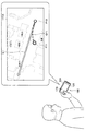
まず、本開示の実施形態に係る情報処理装置100の概要について説明する。図1は、本開示の実施形態に係る情報処理装置100の概要を説明するための図である。図1を参照すると、情報処理装置100は、地図情報171Aを表示部170に表示させている。地図情報171Aにおける2次元座標は、実空間における水平方向の位置(例えば、緯度経度など)と関連付けられている。
<< 1. Overview of information processing equipment >>
First, an overview of the
また、図1を参照すると、ユーザは測位センサ124を所持している。測位センサ124は、ユーザの位置を測定し得る。例えば、測位センサ124によってユーザの位置が測定された場合、情報処理装置100は、地図情報171Aにおいてユーザの位置に対応する位置に所定のマークを表示させてよい。あるいは、ユーザの位置は、測位センサ124によって測定される代わりにユーザによって入力されてもよい。
Also, referring to FIG. 1, the user has a
なお、図1には、情報処理装置100がスマートフォンである場合が示されているが、情報処理装置100の種類は特に限定されない。例えば、情報処理装置100は、ビデオカメラであってもよいし、タブレット端末であってもよいし、PDA(Personal Digital Assistants)であってもよい。あるいは、情報処理装置100は、PC(Personal Computer)であってもよいし、携帯電話であってもよいし、携帯用音楽再生装置であってもよいし、携帯用映像処理装置であってもよいし、携帯用ゲーム機器であってもよい。
Although FIG. 1 shows a case where the
ユーザが目的地を入力すると、情報処理装置100は、地図情報171Aに基づいてユーザの位置から目的地への経路L1の方位を算出することが可能である。また、図1に示したように、情報処理装置100は、経路L1の方位を表示部170に表示させることが可能である。ここで、ユーザにとっては自分自身の方位も把握したいという要求が生じ得る。
When the user inputs a destination, the
そこで、図1に示すように、ユーザは磁気センサ121を所持している。磁気センサ121は、地磁気を含んだ磁気を測定し得る。情報処理装置100は、磁気センサ121によって測定された磁気値に基づいて磁気センサ121の方位を特定することが可能である。情報処理装置100は、磁気センサ121の方位を表示部170に表示させることが可能である。ユーザは、経路L1の方位に磁気センサ121の方位を合わせて進行することによって目的地に到達できると予想する。
Therefore, as shown in FIG. 1, the user has a
しかし、磁気センサ121によって測定される磁気には、地磁気の外乱となる磁気が含まれ得るため、磁気センサ121による地磁気の測定には測定誤差が生じ得る。以下では、地磁気の外乱となる磁気を外乱磁気とも言う。測定誤差を含んだ磁気値に基づいて特定される磁気センサ121の方位には方位誤差が生じ得る。方位誤差を含んだ磁気センサ121の方位に従って進行すれば、ユーザは目的地に辿り着けない可能性がある。
However, since the magnetism measured by the
図1には、ユーザが経路L1の方位に磁気センサ121の方位を合わせて進行した場合におけるユーザ位置の軌跡Q11が示されている。ユーザ位置の軌跡Q11を参照すると、初期位置P10から目的地への経路L1に対して外れた位置P11にユーザが到達してしまっていることが把握される。したがって、磁気センサ121の地磁気センサとしての測定誤差を把握することが有用である。本明細書においては、磁気センサ121の地磁気センサとしてのより高精度な測定誤差を得ることが可能な技術を提案する。
FIG. 1 shows the locus Q11 of the user position when the user travels with the direction of the
以上、本開示の実施形態に係る情報処理装置100の概要について説明した。
The overview of the
<<2.情報処理装置の詳細>>
続いて、本開示の実施形態に係る情報処理装置100の詳細について説明する。
<< 2. Details of information processing equipment >>
Next, details of the
<2−1.情報処理装置の機能構成例>
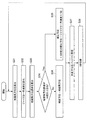
まず、本開示の実施形態に係る情報処理装置100の機能構成例について説明する。図2は、本開示の実施形態に係る情報処理装置100の機能構成例を示す図である。図2に示したように、情報処理装置100は、制御部110、センサ部120、入力部140、記憶部150および表示部170を備える。
<2-1. Functional configuration example of information processing apparatus>
First, a functional configuration example of the
制御部110は、例えば、CPU(Central Processing Unit)などのプロセッサに相当する。制御部110は、記憶部150または他の記憶媒体に記憶されるプログラムを実行することにより、制御部110が有する様々な機能を発揮する。制御部110は、変動測定部111、測定誤差取得部112,特定部113および位置取得部114および表示制御部115を有する。制御部110が有するこれらの各機能部については後に説明する。
The
センサ部120は、所定のセンサデータを検出して制御部110に出力する。図2に示した例では、センサ部120は、磁気センサ121、ジャイロセンサ122、加速度センサ123および測位センサ124を有している。磁気センサ121は磁気値を測定するセンサであり、ジャイロセンサ122は、角速度を測定するセンサであり、加速度センサ123は、加速度を測定するセンサである。以下では、磁気センサ121、ジャイロセンサ122および加速度センサ123それぞれの種類が3軸型である場合について主に説明するが、磁気センサ121、ジャイロセンサ122および加速度センサ123それぞれの種類は特に限定されず、2軸型であってもよい。
The
測位センサ124は、位置を検出するセンサである。位置の表現形式は特に限定されず緯度経度であってよい。測位センサ124は、GPS(Global Positioning System)アンテナを有しており、GPSアンテナによって受信されたGPS信号を用いて算出された位置を検出してよいが、測位センサ124の種類は特に限定されない。例えば、測位センサ124は、基地局からの無線信号を受信するアンテナを有しており、そのアンテナによって受信された無線信号を用いて算出された位置を検出してもよい。図2に示した例では、センサ部120は情報処理装置100に組み込まれているが、センサ部120の一部または全部は情報処理装置100の外部に存在してもよい。
The
入力部140は、ユーザからの操作を受け付ける機能を有する。入力部140は、ユーザから受け付けた操作を制御部110に出力する。操作はプログラムの実行に用いられ得る。例えば、入力部140は、ユーザからプログラムの起動を開始する操作を受け付けることもできる。また、例えば、入力部140は、ユーザからプログラムの実行を終了する操作を受け付けることもできる。図2に示した例では、入力部140は情報処理装置100に組み込まれているが、入力部140は情報処理装置100の外部に存在してもよい。
The
記憶部150は、半導体メモリまたはハードディスクなどの記憶媒体を用いて、制御部110を動作させるためのプログラムを記憶する。また、例えば、記憶部150は、プログラムによって使用される各種のデータ(例えば、各種の設定情報、コンテンツなど)を記憶することもできる。なお、図2に示した例では、記憶部150は情報処理装置100に組み込まれているが、記憶部150は情報処理装置100の外部に存在してもよい。
The
表示部170は、制御部110による制御に従って各種情報の表示を行う。例えば、表示部170は、LCD(Liquid Crystal Display)であってもよいし、有機EL(Electroluminescence)ディスプレイ装置であってもよい。あるいは、表示部170は、スピーカおよびヘッドホンなどの音声出力装置を含んでもよい。なお、図2に示した例では、表示部170は情報処理装置100に組み込まれているが、表示部170は情報処理装置100の外部に存在してもよい。
The
以上、本開示の実施形態に係る情報処理装置100の機能構成例について説明した。
Heretofore, the functional configuration example of the
<2−2.測定誤差の算出>
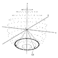
上記したように、磁気センサ121による地磁気の測定には測定誤差が生じ得る。以下では、本開示の実施形態に係る情報処理装置100によって得られる測定誤差について説明する。図3は、本開示の実施形態に係る情報処理装置100によって得られる測定誤差について説明するための図である。具体的に、図3には、測定された磁気値が3軸上にプロットされた結果の例が示されている。
<2-2. Calculation of measurement error>
As described above, measurement errors may occur in the measurement of geomagnetism by the
例えば、測定位置と地磁気の伏角と地磁気の絶対値とが対応付けられた登録情報をデータベースとして用意しておき、登録情報と実測情報との比較結果に基づいて地磁気センサとしての測定誤差を得る一般的な技術を想定する。かかる一般的な技術においては、登録情報と実測情報とにおいて伏角および絶対値が類似していない場合には、測定誤差がより高いと推測され得る。 For example, the registration information in which the measurement position, the geomagnetic dip angle, and the absolute value of the geomagnetism are associated is prepared as a database, and the measurement error as the geomagnetic sensor is obtained based on the comparison result between the registration information and the actual measurement information. Assuming basic technology. In such a general technique, when the dip angle and the absolute value are not similar between the registration information and the actual measurement information, it can be estimated that the measurement error is higher.
一方、かかる一般的な技術においては、登録情報と実測情報とにおいて伏角および絶対値が一致または類似している場合には、測定誤差を推測するのが困難である。第一に、登録情報と実測情報とにおいて伏角および絶対値が一致している場合であっても、測定された磁気値を示す点は円C1上のいずれかにあるということしか把握され得ず、登録情報と実測情報とにおいて方位または姿勢は異なる可能性が想定されるからである。第二に、外乱の影響がどの程度あるかを把握するのが困難だからである。 On the other hand, in such a general technique, it is difficult to estimate a measurement error when the dip angle and the absolute value match or are similar between the registered information and the actually measured information. First, even if the dip angle and the absolute value match between the registration information and the actual measurement information, it can only be understood that the point indicating the measured magnetic value is on one of the circles C1. This is because it is assumed that the registration information and the actual measurement information may have different orientations or orientations. Second, it is difficult to understand how much the influence of disturbance is.
本明細書においては、磁気値または磁気値に基づいて得られる情報の時間的な変動に基づいて測定誤差を得る手法を提案する。磁気値は、磁気値の絶対値(磁気ベクトルの大きさ)であってもよいし、磁気値の何れかの軸方向成分であってもよい。また、磁気値に基づいて得られる情報は、磁気値から得られる伏角であってもよいし、磁気値の絶対値であってもよいし、磁気値から得られる方位であってもよいし、磁気値から得られる姿勢であってもよい。かかる手法によれば、伏角および絶対値以外の情報も測定誤差に反映させることによって、より高精度な測定誤差を得ることが可能となる。また、かかる手法によれば、登録情報をあらかじめ用意しておく必要性がなくなる。 In this specification, a method for obtaining a measurement error based on a magnetic value or a temporal variation of information obtained based on the magnetic value is proposed. The magnetic value may be an absolute value of the magnetic value (magnitude of the magnetic vector) or may be any axial component of the magnetic value. Further, the information obtained based on the magnetic value may be an dip angle obtained from the magnetic value, an absolute value of the magnetic value, or an orientation obtained from the magnetic value, The posture may be obtained from the magnetic value. According to this method, it is possible to obtain a measurement error with higher accuracy by reflecting information other than the dip angle and the absolute value in the measurement error. Further, according to this method, it is not necessary to prepare registration information in advance.
また、本明細書においては、少なくとも磁気センサ121の移動中に磁気値を測定する手法を提案する。かかる手法によれば、磁気センサ121の移動中に測定された空間的な磁気分布が測定誤差に反映されるようになる。空間的な磁気分布は測定誤差との相関性が高いことが推測される。したがって、かかる手法によれば、より高精度な測定誤差を得ることが可能となる。
In the present specification, a method for measuring a magnetic value at least while the
図4は、本開示の実施形態に係る情報処理装置100によって得られる測定誤差について説明するための他の図である。図4を参照すると、鉄鋼材質の建物の領域R1が存在し、領域R1に囲まれた領域R2が存在している。ここで、領域R2においては、領域R1と比較して磁束が疎になり易いため、磁気値の絶対値は小さくなり得るが、登録情報の精度によっては領域R2において登録されている地磁気の絶対値が領域R1において登録されている地磁気の絶対値と同程度になってしまっていることもあり得る。そのため、上記の一般的な技術においては、領域R2において登録情報と実測情報とにおいて絶対値が類似していないと判断され、方位誤差がさほど高くない場合であっても測定誤差が高いと推測され得る。
FIG. 4 is another diagram for describing the measurement error obtained by the
本明細書においては、磁気値または磁気値に基づいて得られる情報の時間的な変動に基づいて測定誤差を得る手法を提案する。かかる手法によれば、実測情報と登録情報とを比較する必要がなくなるため、登録情報の精度の高さに依存しない、より高精度な測定誤差を得ることが可能となる。 In this specification, a method for obtaining a measurement error based on a magnetic value or a temporal variation of information obtained based on the magnetic value is proposed. According to this method, since it is not necessary to compare the actual measurement information and the registration information, it is possible to obtain a more accurate measurement error that does not depend on the accuracy of the registration information.
また、本明細書においては、少なくとも磁気センサ121の移動中に磁気値を測定する手法を提案する。かかる手法によれば、磁気センサ121の移動中に測定された空間的な磁気分布が測定誤差に反映されるようになる。磁束が疎になり易い領域R2において、方位誤差がさほど高くない場合には、空間的な磁気分布もさほど変化しない可能性があり、上記の一般的な技術と比較して低めの測定誤差がより高精度に得られる可能性がある。
In the present specification, a method for measuring a magnetic value at least while the
続いて、本開示の実施形態に係る情報処理装置100が測定誤差を得る手法についてさらに詳細に説明する。まず、変動測定部111は、少なくとも磁気センサ121の移動中に磁気センサ121によって測定された磁気値または磁気値に基づいて得られる情報の時間的な変動を測定する。測定誤差取得部112は、変動測定部111によって測定された変動に基づいて磁気センサ121の地磁気センサとしての測定誤差を得る。かかる手法によれば、上記したようにより高精度な測定誤差を得ることが可能となる。
Subsequently, a method in which the
磁気センサ121の移動中であるか否かは、制御部110によって自動的に判断されてもよいし、ユーザによって入力されてもよい。磁気センサ121の移動中であるか否かの判断はどのようになされてもよく、センサ部120によって測定されたセンサデータに基づいてなされてもよい。例えば、制御部110は、測位センサ124によって測定された測位位置が変化した場合に、磁気センサ121が移動中であると判断してもよいし、歩数計によって磁気センサ121が移動中であるか否かが判断されてもよい。なお、変動測定部111は、磁気センサ121の停止中に変動を測定してもよい。
Whether or not the
変動測定部111による変動の測定としては様々な測定の手法が想定される。例えば、変動測定部111は、所定の2つの測定時刻を第1の測定時刻および第2の測定時刻とし、第1の測定時刻および第2の測定時刻それぞれにおける磁気値または磁気値に基づいて得られる情報の差分値を変動として測定してよい。このようにして差分値を変動として測定すれば、簡易な処理によって変動を測定することが可能となる。
Various measurement methods are assumed as the measurement of the fluctuation by the
第1の測定時刻および第2の測定時刻それぞれはどのような時刻であってもよいが、例えば、所定時間内に測定された磁気値または磁気値に基づいて得られる情報のうち、第1の測定時刻が最大値であり第2の測定時刻が最小値であってもよい。以下においては、第1の測定時刻が最大値であり第2の測定時刻が最小値である場合について、図5および図6を参照しながら説明する。図5および図6には、所定時間が10秒である場合が示されているが、所定時間の長さは限定されない。 Each of the first measurement time and the second measurement time may be any time. For example, among the magnetic values measured within a predetermined time or the information obtained based on the magnetic values, the first measurement time and the second measurement time The measurement time may be a maximum value and the second measurement time may be a minimum value. Hereinafter, the case where the first measurement time is the maximum value and the second measurement time is the minimum value will be described with reference to FIGS. 5 and 6. 5 and 6 show a case where the predetermined time is 10 seconds, but the length of the predetermined time is not limited.
なお、以下では、方位の特定に測定誤差を利用することを想定し、測定誤差の例として方位誤差を用いる場合を主に説明するが、測定誤差は方位の特定以外に利用されてもよい。また、以下では、変動測定部111が磁気センサ121によって測定された磁気値の時間的な変動を測定する場合を主に説明するが、変動測定部111は、磁気値に基づいて得られる情報の時間的な変動を測定してもよい。
In the following description, it is assumed that a measurement error is used for specifying the azimuth, and the case where the azimuth error is used as an example of the measurement error will be mainly described. However, the measurement error may be used other than specifying the azimuth. In the following description, the case where the
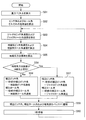
図5は、磁気値の絶対値と方位誤差との関係の一例を示す図である。また、図6は、磁気値に基づいて方位誤差を得る動作の一例を示すフローチャートである。まず、磁気センサ121は、3軸磁気値を検出し(S11)、検出した3軸磁気値からオフセットを除去する(S12)。変動測定部111は、3軸磁気値の絶対値を算出してバッファに蓄積する(S13)。3軸磁気値の絶対値は、図5に示されているように変化し得る。制御部110は、10秒分の絶対値がバッファに蓄積されていない場合には(S14において「No」)、S11に動作を移行させる。
FIG. 5 is a diagram illustrating an example of the relationship between the absolute value of the magnetic value and the azimuth error. FIG. 6 is a flowchart showing an example of an operation for obtaining an azimuth error based on a magnetic value. First, the
一方、測定誤差取得部112は、10秒分の絶対値がバッファに蓄積された場合には(S14において「Yes」)、バッファに蓄積された10秒分の絶対値のうち最大値から最小値を減算して差分値を算出し(S15)、差分値に固定係数を乗じることによって方位誤差を算出する(S16)。図5には、バッファに蓄積された10秒分の絶対値のうちの最大値と最小値とが示されている。制御部110は、3軸地磁気の絶対値の蓄積位置を示すバッファポインタをインクリメントし(S17)、S11に動作を移行させる。
On the other hand, when the absolute value for 10 seconds is accumulated in the buffer (“Yes” in S14), the measurement
なお、ここでは所定時間内に測定された磁気値または磁気値に基づいて得られる情報のうち、第1の測定時刻が最大値であり第2の測定時刻が最小値である例を説明したが、上記したように、第1の測定時刻および第2の測定時刻それぞれはどのような時刻であってもよい。例えば、第1の測定時刻と第2の測定時刻とは、互いに所定時間の隔たりを有していてもよい。 Here, an example has been described in which the first measurement time is the maximum value and the second measurement time is the minimum value among the magnetic values measured within a predetermined time or information obtained based on the magnetic values. As described above, each of the first measurement time and the second measurement time may be any time. For example, the first measurement time and the second measurement time may be separated from each other by a predetermined time.
以下においては、第1の測定時刻と第2の測定時刻とが互いに所定時間の隔たりを有する場合について、図7を参照しながら説明する。図7には、所定時間が1秒である場合が示されているが、所定時間の長さは限定されない。 In the following, a case where the first measurement time and the second measurement time are separated from each other by a predetermined time will be described with reference to FIG. Although FIG. 7 shows a case where the predetermined time is 1 second, the length of the predetermined time is not limited.
図7は、磁気値に基づいて方位誤差を得る動作の他の一例を示すフローチャートである。まず、磁気センサ121は、3軸磁気値を検出し(S21)、検出した3軸磁気値からオフセットを除去する(S22)。変動測定部111は、3軸磁気値の絶対値を算出してバッファに蓄積する(S23)。制御部110は、1秒分の絶対値がバッファに蓄積されていない場合には(S24において「No」)、S21に動作を移行させる。
FIG. 7 is a flowchart showing another example of the operation for obtaining the azimuth error based on the magnetic value. First, the
一方、測定誤差取得部112は、1秒分の絶対値がバッファに蓄積された場合には(S24において「Yes」)、バッファに蓄積された1秒分の絶対値のうち現在の絶対値から1秒前の絶対値を減算して差分値を算出し(S25)、差分値に固定係数を乗じることによって方位誤差を算出する(S26)。制御部110は、3軸地磁気の絶対値の蓄積位置を示すバッファポインタをインクリメントし(S27)、S21に動作を移行させる。
On the other hand, when the absolute value for one second is accumulated in the buffer (“Yes” in S24), the measurement
なお、図6および図7には、測定誤差取得部112が、差分値と固定係数との乗算結果を磁気センサ121の方位誤差として算出する例が示されているが、方位誤差の算出手法はかかる例に限定されない。例えば、測定誤差取得部112は、差分値自体を磁気センサ121の方位誤差として得てもよい。したがって、測定誤差取得部112は、差分値と固定係数との乗算結果または差分値を磁気センサ121の測定誤差として得てよい。
6 and 7 show an example in which the measurement
以上、本開示の実施形態に係る情報処理装置100によって得られる測定誤差について説明した。
Heretofore, the measurement error obtained by the
<2−3.方位または姿勢の特定>
以上に説明したようにして得られる測定誤差はどのようにして利用されてもよい。例えば、特定部113は、磁気センサ121の測定誤差に基づいて方位または姿勢を特定してよい。まず、磁気センサ121の方位または姿勢の特定に用いられ得る磁気センサ121の姿勢角としてヨー角、ロール角およびピッチ角について説明する。図8は、ヨー角、ロール角およびピッチ角を説明するための図である。
<2-3. Identification of orientation or posture>
The measurement error obtained as described above may be used in any way. For example, the specifying
図8に示したように、情報処理装置100の前方ベクトルに沿ってロール軸(Y軸)が設定されてよい。また、情報処理装置100の左右方向に沿ってピッチ軸(X軸)が設定されてよい。ヨー軸(Z軸)は、重力ベクトルに沿って設定されてよい。以下の説明においては、ピッチ角、ロール角およびヨー角は、ピッチ軸、ロール軸およびヨー軸それぞれに対する回転角に相当する。また、ヨー角は方位に相当し、ピッチ角およびロール角は姿勢に相当し得る。
As illustrated in FIG. 8, the roll axis (Y axis) may be set along the front vector of the
磁気センサ121の測定誤差に基づいて方位または姿勢を特定する手法は特に限定されないが、特定部113は、磁気センサ121の測定誤差が高いほど、他のセンサデータを用いた方位または姿勢に対する補正の重みを強めてよい。かかる構成によれば、より高精度に方位または姿勢を特定することが可能となる。他のセンサデータを用いた方位または姿勢に対する補正の重みを強める手法についても特に限定されない。
The method for specifying the azimuth or orientation based on the measurement error of the
例えば、特定部113は、磁気センサ121の測定誤差が閾値を上回る場合には、他のセンサデータに基づいて方位または姿勢を補正してよい。他のセンサデータも特に限定されないが、ジャイロセンサ122により測定された角速度であってよい。したがって、特定部113は、磁気センサ121の測定誤差が閾値を上回る場合には、ジャイロセンサ122により測定された角速度に基づいて方位または姿勢を補正してよい。かかる補正についてさらに具体的に説明する。
For example, when the measurement error of the
図9は、方位誤差に基づいて方位を特定する動作の一例を示すフローチャートである。まず、制御部110は、磁気センサ121によって検出された磁気値に基づく方位(以下、「地磁気方位」とも言う。)を算出する(S31)。また、制御部110は、ジャイロセンサ122によって検出された角速度に基づくヨー角速度(以下、「ジャイロヨー角速度」とも言う。)を算出する(S32)。ヨー軸の方向は、加速度センサ123によって検出された加速度から推定された重力ベクトルに基づいて定められてよい。
FIG. 9 is a flowchart illustrating an example of an operation for specifying the azimuth based on the azimuth error. First, the
続いて、変動測定部111は、少なくとも磁気センサ121の移動中に磁気センサ121によって測定された磁気値または磁気値に基づいて得られる情報の時間的な変動を測定し、測定誤差取得部112は、変動測定部111によって測定された変動に基づいて磁気センサ121の地磁気センサとしての測定誤差(以下、「地磁気方位誤差」とも言う。)を算出する(S33)。
Subsequently, the
特定部113は、地磁気方位誤差が10度を上回る場合には(S34において「Yes」)、1秒前の補正方位に対してジャイロヨー角速度と1秒との乗算結果を加算することによって新たな補正方位を算出し(S35)、S37に動作が移行される。一方、特定部113は、地磁気方位誤差が10度を下回る場合には(S34において「No」)、地磁気方位を新たな補正方位とし(S36)、S37に動作が移行される。地磁気方位誤差が10度と等しい場合には、S35およびS36の何れに動作が移行されてもよい。
When the geomagnetic azimuth error exceeds 10 degrees (“Yes” in S34), the specifying
特定部113は、補正方位をバッファに蓄積し(S37)、制御部110は、1秒待機して(S38)、S31に動作を移行させる。なお、図9には、地磁気方位誤差と比較される閾値が10度である場合が示されているが、かかる閾値の大きさは限定されない。また、図9には、方位の補正が1秒ごとになされる場合が示されているが、方位の補正がなされる時間間隔は限定されず、適宜に変更されてよい。
The specifying
以上においては、磁気センサ121の測定誤差に基づいて方位または姿勢を特定する例を説明したが、特定部113は、磁気センサ121の測定誤差と他のセンサの測定誤差とに基づいて方位または姿勢を特定してもよい。磁気センサ121の測定誤差と他のセンサの測定誤差とに基づいて方位または姿勢を特定する手法は特に限定されない。
In the above, the example in which the orientation or orientation is specified based on the measurement error of the
例えば、特定部113は、磁気センサ121の測定誤差が他のセンサの測定誤差を上回る場合に、他のセンサにより測定されたセンサデータに基づいて方位または姿勢を補正してもよい。かかる構成によれば、より高精度に方位または姿勢を特定することが可能となる。他のセンサも特に限定されないが、ジャイロセンサ122であってよい。したがって、特定部113は、磁気センサ121の測定誤差がジャイロセンサ122の測定誤差を上回る場合には、ジャイロセンサ122により測定された角速度に基づいて方位または姿勢を補正してよい。かかる補正についてさらに具体的に説明する。
For example, when the measurement error of the
図10は、方位誤差に基づいて方位を特定する動作の他の一例を示すフローチャートである。まず、制御部110は、地磁気方位を算出する(S41)。また、制御部110は、ジャイロヨー角速度を算出する(S42)。ヨー軸の方向は、加速度センサ123によって検出された加速度から推定された重力ベクトルに基づいて定められてよい。続いて、変動測定部111は、少なくとも磁気センサ121の移動中に磁気センサ121によって測定された磁気値または磁気値に基づいて得られる情報の時間的な変動を測定し、測定誤差取得部112は、変動測定部111によって測定された変動に基づいて地磁気方位誤差を算出する(S43)。
FIG. 10 is a flowchart showing another example of the operation for specifying the azimuth based on the azimuth error. First, the
測定誤差取得部112は、ジャイロセンサ122の測定誤差(以下、「ジャイロ方位誤差」とも言う。)を算出する(S44)。ジャイロセンサ122の測定誤差の算出手法は特に限定されないが、オフセット補正を行った時点からの経過時間が長いほど、ジャイロセンサ122の測定誤差は長くなり得るという特性を考慮し、ジャイロセンサ122に対して前回オフセット補正がなされた時点からの経過時間がジャイロセンサ122の測定誤差として算出されてもよい。
The measurement
特定部113は、地磁気方位誤差がジャイロ方位誤差を上回る場合には(S45において「Yes」)、1秒前の補正方位に対してジャイロヨー角速度と1秒との乗算結果を加算することによって新たな補正方位を算出し(S46)、S48に動作が移行される。一方、特定部113は、地磁気方位誤差がジャイロ方位誤差を下回る場合には(S45において「No」)、地磁気方位を新たな補正方位とし(S47)、制御部110は、S48に動作が移行される。地磁気方位誤差がジャイロ方位誤差と等しい場合には、S46およびS47の何れに動作が移行されてもよい。
If the geomagnetic azimuth error exceeds the gyro azimuth error (“Yes” in S45), the specifying
特定部113は、補正方位をバッファに蓄積し(S48)、制御部110は、1秒待機して(S49)、S41に動作を移行させる。なお、図10には、方位の補正が1秒ごとになされる場合が示されているが、方位の補正がなされる時間間隔は限定されず、適宜に変更されてよい。
The specifying
図11は、本開示の実施形態に係る情報処理装置100および一般的な技術それぞれを用いた場合におけるユーザ位置の軌跡の一例を示す図である。図11を参照しながら、本開示の実施形態に係る情報処理装置100および一般的な技術それぞれを用いた場合におけるユーザ位置の軌跡の相違の一例を説明する。地図情報171Bを参照すると、ユーザ位置の軌跡が示されている。
FIG. 11 is a diagram illustrating an example of the locus of the user position when the
具体的には、変動測定部111および測定誤差取得部112によって得られた測定誤差を用い、図10に示したような地磁気方位誤差とジャイロ方位誤差との比較結果に基づいて方位を特定した場合におけるユーザ位置の軌跡Q11が示されている。一方、上記の一般的な技術による測定誤差を用い、図10に示したような地磁気方位誤差とジャイロ方位誤差との比較結果に基づいて方位を特定した場合におけるユーザ位置の軌跡Q12が示されている。
Specifically, when the measurement error obtained by the
ここで、一般的に屋内においては屋外よりも地磁気の大きさが弱くなる傾向がある。例えば、屋内をユーザが進行している状況において、登録情報と実測情報とを比較する一般的な技術を用いた場合には、磁気値の絶対値が小さくなり易く地磁気方位誤差が大きくない易い。その結果として地磁気方位誤差がジャイロ方位誤差を上回り易く、ジャイロセンサによって測定された角速度に基づいて方位が特定され易い。しかし、ジャイロセンサの測定結果にはオフセット誤差が含まれるため、ジャイロセンサによって測定された角速度が蓄積されていくと、軌跡Q12に示すように測定誤差が次第に大きくなっていく。 Here, generally, the magnitude of geomagnetism tends to be weaker indoors than outdoors. For example, in a situation where a user is traveling indoors, when a general technique for comparing registered information and measured information is used, the absolute value of the magnetic value tends to be small and the geomagnetic orientation error is not likely to be large. As a result, the geomagnetic azimuth error tends to exceed the gyro azimuth error, and the azimuth is easily specified based on the angular velocity measured by the gyro sensor. However, since the measurement result of the gyro sensor includes an offset error, when the angular velocity measured by the gyro sensor is accumulated, the measurement error gradually increases as indicated by the locus Q12.
一方、例えば、同様の状況において、変動測定部111および測定誤差取得部112によって得られた測定誤差を用いた場合には、地磁気方位誤差はさほど大きくならないため、ユーザが位置P11に到達した時点において地磁気方位誤差がジャイロ方位誤差を下回っている。ユーザが位置P11およびP12に到達したときには、磁気センサ121によって測定された磁気値に基づいて方位が特定されるため、ユーザ位置の軌跡Q11は、経路L1からさほど外れていないことが把握される。
On the other hand, for example, in the same situation, when the measurement error obtained by the
図12は、本開示の実施形態に係る情報処理装置100および一般的な技術それぞれを用いた場合におけるユーザ位置の軌跡の他の一例を示す図である。図12を参照しながら、本開示の実施形態に係る情報処理装置100および一般的な技術それぞれを用いた場合におけるユーザ位置の軌跡の相違の他の一例を説明する。地図情報171Cを参照すると、ユーザ位置の軌跡が示されている。
FIG. 12 is a diagram illustrating another example of the locus of the user position when the
図12においても、ユーザ位置の軌跡Q11およびQ12が示されている。例えば、屋内をユーザが進行している状況において、登録情報と実測情報とを比較する一般的な技術を用いた場合には、軌跡Q12に示すように測定誤差が次第に大きくなっていく。ここで、上記したように、登録情報と実測情報とにおいて伏角および絶対値が一致または類似している場合であっても、登録情報と実測情報とにおいて伏角および絶対値が一致している場合には地磁気方位誤差が低いと推測され易いが、登録情報と実測情報とにおいて方位は異なっている可能性がある。 Also in FIG. 12, the locus Q11 and Q12 of the user position are shown. For example, in a situation where the user is traveling indoors, when a general technique for comparing registration information and actual measurement information is used, the measurement error gradually increases as shown by a trajectory Q12. Here, as described above, even when the dip angle and the absolute value are the same or similar between the registered information and the measured information, the dip angle and the absolute value are the same between the registered information and the measured information. However, it is likely that the geomagnetic orientation error is low, but the orientation may be different between the registered information and the measured information.
ユーザが位置P13に到達した時点において地磁気方位誤差がジャイロ方位誤差を下回ったとする。ユーザが位置P13に到達したときには、磁気センサ121によって測定された磁気値に基づいて方位が特定されるが、実際には測定された方位は誤っているため、ユーザ位置の軌跡Q12は、ユーザが位置P13に到達した後において経路L1からさらに大きく外れていることが把握される。
It is assumed that the geomagnetic azimuth error is less than the gyro azimuth error when the user reaches the position P13. When the user reaches the position P13, the azimuth is specified based on the magnetic value measured by the
図13は、本開示の実施形態に係る情報処理装置100および一般的な技術それぞれを用いた場合における複数のユーザ位置の軌跡の一例を示す図である。図13を参照しながら、本開示の実施形態に係る情報処理装置100および一般的な技術それぞれを用いた場合における複数のユーザ位置の軌跡の一例を説明する。地図情報171Dを参照すると、第1のユーザ位置および第2のユーザ位置それぞれの軌跡が示されている。第1のユーザは、初期位置P10から経路L1の方位に進行しようとしており、第2のユーザは、初期位置P20から経路L2の方位に進行しようとしている。
FIG. 13 is a diagram illustrating an example of trajectories of a plurality of user positions when the
具体的には、変動測定部111および測定誤差取得部112によって得られた測定誤差を用い、図10に示したような地磁気方位誤差とジャイロ方位誤差との比較結果に基づいて方位を特定した場合における第1のユーザ位置の軌跡Q11および第2のユーザ位置の軌跡Q21が示されている。一方、上記の一般的な技術による測定誤差を用い、図10に示したような地磁気方位誤差とジャイロ方位誤差との比較結果に基づいて方位を特定した場合における第1のユーザ位置の軌跡Q12および第2のユーザ位置の軌跡Q22が示されている。
Specifically, when the measurement error obtained by the
一般的な技術を用いた場合における第1のユーザ位置の軌跡Q12と第2のユーザ位置の軌跡Q22とを参照すると、第1のユーザと第2のユーザとは経路L1および経路L2の合流地点からは離れてしまっていることが把握される。一方、本開示の実施形態に係る情報処理装置100を用いた場合における第1のユーザ位置の軌跡Q11と第2のユーザ位置の軌跡Q21とを参照すると、第1のユーザと第2のユーザとは経路L1および経路L2の合流地点に近づいていることが把握される。
Referring to the trajectory Q12 of the first user position and the trajectory Q22 of the second user position when a general technique is used, the first user and the second user are merged points of the route L1 and the route L2. It is understood that it has left. On the other hand, referring to the trajectory Q11 of the first user position and the trajectory Q21 of the second user position when the
図14は、方位誤差に基づいて姿勢を特定する動作の一例を示すフローチャートである。まず、制御部110は、加速度センサ123によって検出された加速度から重力ベクトルを算出する(S51)。また、制御部110は、重力ベクトルからピッチ角およびロール角それぞれの初期値を算出する(S52)。続いて、制御部110は、ジャイロセンサ122によって検出されたピッチ角速度(以下、「ジャイロピッチ角速度」とも言う。)およびロール角速度(以下、「ジャイロロール角速度」とも言う。)を検出する(S53)。
FIG. 14 is a flowchart illustrating an example of an operation for specifying a posture based on an azimuth error. First, the
続いて、制御部110は、磁気センサ121によって検出された磁気値に基づいてピッチ角速度(以下、「地磁気ピッチ角速度」とも言う。)およびロール角速度(以下、「地磁気ロール角速度」とも言う。)を算出する(S54)。具体的には、制御部110は、XZ平面およびYZ平面それぞれに地磁気ベクトルを射影したときの偏角を地磁気ロール角および地磁気ピッチ角とし、1秒前からの変化量を地磁気ロール角速度および地磁気ピッチ角速度として算出すればよい。
Subsequently, the
続いて、変動測定部111は、少なくとも磁気センサ121の移動中に磁気センサ121によって測定された磁気値または磁気値に基づいて得られる情報の時間的な変動を測定し、測定誤差取得部112は、変動測定部111によって測定された変動に基づいて地磁気方位誤差を算出する(S55)。
Subsequently, the
特定部113は、地磁気方位誤差が10度を上回る場合には(S56において「Yes」)、1秒前の補正ピッチ角に対してジャイロピッチ角速度を加算することによって新たな補正ピッチ角を算出するとともに、1秒前の補正ロール角に対してジャイロロール角速度を加算することによって新たな補正ロール角を算出し(S57)、S59に動作が移行される。一方、特定部113は、地磁気方位誤差が10度を下回る場合には(S56において「No」)、1秒前の補正ピッチ角に対して地磁気ピッチ角速度を加算することによって新たな補正ピッチ角を算出するとともに、1秒前の補正ロール角に対して地磁気ロール角速度を加算することによって新たな補正ロール角を算出し(S58)、S59に動作が移行される。地磁気方位誤差が10度と等しい場合には、S57およびS58の何れに動作が移行されてもよい。
When the geomagnetic azimuth error exceeds 10 degrees (“Yes” in S56), the specifying
特定部113は、補正ピッチ角、補正ロール角および磁気値をバッファに蓄積し(S59)、制御部110は、1秒待機して(S60)、S53に動作を移行させる。なお、図14には、地磁気方位誤差と比較される閾値が10度である場合が示されているが、かかる閾値の大きさは限定されない。また、図14には、方位の補正が1秒ごとになされる場合が示されているが、方位の補正がなされる時間間隔は限定されず、適宜に変更されてよい。
The specifying
以上、磁気センサ121の測定誤差に基づいて方位または姿勢を特定する手法について説明した。なお、表示制御部115は、磁気センサ121の方位または姿勢を表示部170に表示させることが可能である。また、表示部170は、磁気センサ121の方位または姿勢を表示することが可能である。
The method for specifying the azimuth or orientation based on the measurement error of the
<2−4.測位位置の補正>
以上においては、センサデータを用いて方位または姿勢を特定する手法を説明した。しかし、本開示の実施形態に係る情報処理装置100による方位または姿勢の特定は、様々な機能と併用されることによって、さらに格別な効果を奏することが期待される。例えば、情報処理装置100による方位または姿勢の特定は、マップマッチングの技術を用いた測位位置の補正とも併用され得る。図15は、マップマッチング技術を用いた測位位置の補正の一例を示す図である。
<2-4. Positioning correction>
In the above, the method for specifying the azimuth or posture using the sensor data has been described. However, it is expected that the specification of the azimuth or posture by the
位置取得部114は、測位センサ124により測定された測定位置を取得する。地図情報171Eに示したように、表示制御部115は、位置取得部114によって取得された測位位置を表示部170に表示させることが可能である。表示部170は、位置取得部114によって取得された測位位置を表示することが可能である。ここで、位置取得部114は、マップマッチング技術を用いて、あらかじめ登録された位置情報に基づいて測定位置を補正してよい。
The
図15に示した例では、ユーザが存在することが可能な位置C11およびC12それぞれを示す位置情報があらかじめ登録されており、位置取得部114は、本開示の実施形態に係る情報処理装置100を用いた場合における測位位置を位置C11に補正している。また、位置取得部114は、一般的な技術を用いた場合における測位位置を位置C12に補正している。測位位置の補正は、測位位置があらかじめ登録された位置情報が示す位置に一致または類似した場合になされてよい。図15を参照すると、本開示の実施形態に係る情報処理装置100を用いた場合には、経路L1に沿った位置C11に測位位置が補正されているが、一般的な技術を用いた場合には、経路L1とは外れた位置C12に測位位置が補正されている。
In the example illustrated in FIG. 15, position information indicating each of the positions C11 and C12 where the user can exist is registered in advance, and the
この例のように、方位または姿勢の特定の精度が向上すれば、特に方位または姿勢の特定技術とマップマッチング技術とが併用された場合に、誤った位置に測位位置が補正されてしまう可能性を低減することが可能となる。特に、図15に示したような徒歩道は、車両道路よりも2次元的に幅を有する可能性が高く、徒歩道をユーザが進行している間にはマップマッチング技術の適用がなされにくい。そのため、特に徒歩道をユーザが進行している間には、本開示の実施形態に示したように高精度に方位が特定されることが効果的である。 If the accuracy of specifying the direction or orientation is improved as in this example, the positioning position may be corrected to the wrong position, especially when the orientation or orientation specification technology and the map matching technology are used in combination. Can be reduced. In particular, the walking path as shown in FIG. 15 is more likely to have a two-dimensional width than the vehicle road, and the map matching technique is not easily applied while the user is traveling on the walking path. Therefore, it is effective that the direction is specified with high accuracy as shown in the embodiment of the present disclosure, particularly while the user is traveling on a walking path.
以上、情報処理装置100による方位または姿勢の特定がマップマッチングの技術を用いた測位位置の補正と併用される場合について説明したが、例えば、情報処理装置100による方位または姿勢の特定は、ユーザの通行履歴を記憶させる技術とも併用され得る。図16は、通行履歴を記憶させる例を説明するための図である。
As described above, the description has been given of the case where the specification of the azimuth or orientation by the
位置取得部114は、測位センサ124により測定された測定位置を取得する。地図情報171Fに示したように、表示制御部115は、位置取得部114によって取得された測位位置を表示部170に表示させることが可能である。また、表示部170は、位置取得部114によって取得された測位位置を表示することが可能である。ここで、位置取得部114は、測定位置に一致または近接する位置情報に関連付けられたエリア識別情報を選択してユーザの通行履歴として記憶させてよい。
The
図16に示した例では、ユーザが存在することが可能なエリアE11およびE12それぞれを識別するためのエリア識別情報があらかじめ登録されており、それぞれのエリア識別情報には位置情報が関連付けられている。エリアの種類は特に限定されず、店舗などといった動きのないものの存在場所であってもよいし、人、乗り物、屋台、イベント(花火大会など)の場所などといった動きのあるものの存在場所であってもよい。図16に示した例では、エリアE11が改札口であり、エリアE12が地下街に存在する店舗である。 In the example shown in FIG. 16, area identification information for identifying each of the areas E11 and E12 in which the user can exist is registered in advance, and position information is associated with each area identification information. . The type of area is not particularly limited, and may be a place where there is no movement such as a store, or a place where there is movement such as a place of people, vehicles, stalls, events (fireworks display etc.) Also good. In the example shown in FIG. 16, area E11 is a ticket gate, and area E12 is a store in an underground mall.
また、図16に示した例では、位置取得部114は、本開示の実施形態に係る情報処理装置100を用いた場合における測位位置に近接する位置情報を取得し、この位置情報に関連付けられたエリアE11のエリア識別情報を選択してユーザの通行履歴として記憶させている。また、位置取得部114は、一般的な技術を用いた場合における測位位置に近接する位置情報を取得し、この位置情報に関連付けられたエリアE12のエリア識別情報を選択してユーザの通行履歴として記憶させている。
In the example illustrated in FIG. 16, the
図16を参照すると、本開示の実施形態に係る情報処理装置100を用いた場合には、経路L1に沿ったエリアE11のエリア識別情報が進行履歴として記憶されるが、一般的な技術を用いた場合には、経路L1とは外れたエリアE12のエリア識別情報が進行履歴として記憶されてしまう。
Referring to FIG. 16, when the
この例のように、方位または姿勢の特定の精度が向上すれば、特に方位または姿勢の特定技術とユーザの通行履歴を記憶させる技術とが併用された場合に、誤った通行履歴が記憶されてしまう可能性を低減することが可能となる。このようにして得られた通行履歴はどのように利用されてもよい。例えば、通行履歴を分析することによってユーザの嗜好情報を得ることも可能となる。 As shown in this example, if the accuracy of specifying the azimuth or orientation is improved, an erroneous passage history is stored, particularly when the azimuth or posture identification technology and the technology for storing the user's passage history are used in combination. It is possible to reduce the possibility of being lost. The traffic history obtained in this way may be used in any way. For example, it becomes possible to obtain user preference information by analyzing the traffic history.
以上においては、情報処理装置100による方位または姿勢の特定が、マップマッチングの技術を用いた測位位置の補正と併用される場合や、ユーザの通行履歴を記憶させる技術と併用される場合について説明した。しかし、情報処理装置100による方位または姿勢の特定は、他の技術と併用されても格別な効果を奏し得る。
In the above, description has been given of the case where the specification of the azimuth or orientation by the
例えば、情報処理装置100による方位または姿勢の特定は、ユーザ位置とユーザの方位とに基づいてユーザが到達するエリアを推測する技術とも併用され得る。また、情報処理装置100による方位または姿勢の特定は、通行履歴に基づいてユーザの存在するエリアを推測する技術とも併用され得る。情報処理装置100による方位または姿勢の特定は、時間帯ごとの通行履歴に基づいて、ある時間帯においてユーザの存在するエリアを推測する技術とも併用され得る。
For example, the specification of the azimuth or orientation by the
<<3.ハードウェア構成例>>
続いて、本開示の実施形態に係る情報処理装置100のハードウェア構成例について説明する。図17は、本開示の実施形態に係る情報処理装置100のハードウェア構成例を示す図である。ただし、図17に示したハードウェア構成例は、情報処理装置100のハードウェア構成の一例を示したに過ぎない。したがって、情報処理装置100のハードウェア構成は、図17に示した例に限定されない。
<< 3. Hardware configuration example >>
Subsequently, a hardware configuration example of the
図17に示したように、情報処理装置100は、CPU(Central Processing Unit)801と、ROM(Read Only Memory)802と、RAM(Random Access Memory)803と、センサ804と、入力装置808と、出力装置810と、ストレージ装置811と、ドライブ812とを備える。
As shown in FIG. 17, the
CPU801は、演算処理装置および制御装置として機能し、各種プログラムに従って情報処理装置100内の動作全般を制御する。また、CPU801は、マイクロプロセッサであってもよい。ROM802は、CPU801が使用するプログラムや演算パラメータ等を記憶する。RAM803は、CPU801の実行において使用するプログラムや、その実行において適宜変化するパラメータ等を一時記憶する。これらはCPUバスなどから構成されるホストバスにより相互に接続されている。
The
センサ804は、情報処理装置100の状態を検出するためのセンサとその周辺回路からなる。センサ804としては、磁気センサ、ジャイロセンサ、加速度センサ、測位センサなどを挙げることができる。センサ804により検出されたセンサデータは、CPU801に送られる。これにより、CPU801は、情報処理装置100の状態(方位、角速度、加速度、位置など)を知ることができる。
The
入力装置808は、マウス、キーボード、タッチパネル、ボタン、マイクロフォン、スイッチおよびレバーなどユーザが情報を入力するための入力部と、ユーザによる入力に基づいて入力信号を生成し、CPU801に出力する入力制御回路などから構成されている。情報処理装置100のユーザは、該入力装置808を操作することにより、情報処理装置100に対して各種のデータを入力したり処理動作を指示したりすることができる。
The
出力装置810は、例えば、液晶ディスプレイ(LCD)装置、OLED(Organic Light Emitting Diode)装置およびランプなどの表示装置を含む。さらに、出力装置810は、スピーカおよびヘッドホンなどの音声出力装置を含んでもよい。例えば、表示装置は、撮像された画像や生成された画像などを表示する。一方、音声出力装置は、音声データを音声に変換して出力する。
The
ストレージ装置811は、情報処理装置100の記憶部の一例として構成されたデータ格納用の装置である。ストレージ装置811は、記憶媒体、記憶媒体にデータを記録する記録装置、記憶媒体からデータを読み出す読出し装置および記憶媒体に記録されたデータを削除する削除装置などを含んでもよい。このストレージ装置811は、CPU801が実行するプログラムや各種データを格納する。
The
ドライブ812は、記憶媒体用リーダライタであり、情報処理装置100に内蔵、あるいは外付けされる。ドライブ812は、装着されている磁気ディスク、光ディスク、光磁気ディスク、または半導体メモリなどのリムーバブル記憶媒体に記録されている情報を読み出して、RAM803に出力する。また、ドライブ812は、リムーバブル記憶媒体に情報を書き込むこともできる。
The
以上、本開示の実施形態に係る情報処理装置100のハードウェア構成例について説明した。
Heretofore, the hardware configuration example of the
<<4.むすび>>
以上説明したように、本開示の実施形態によれば、少なくとも磁気センサの移動中に磁気センサ121によって測定された磁気値または磁気値に基づいて得られる情報の時間的な変動を測定する変動測定部111と、変動に基づいて磁気センサ121の測定誤差を得る測定誤差取得部112と、を備える、情報処理装置100が提供される。
<< 4. Conclusion >>
As described above, according to the embodiment of the present disclosure, at least during the movement of the magnetic sensor, the magnetic value measured by the
かかる構成によれば、磁気センサ121の移動中に測定された空間的な磁気分布が測定誤差に反映されるようになる。空間的な磁気分布は測定誤差との相関性が高いことが推測される。したがって、かかる手法によれば、より高精度な測定誤差を得ることが可能となる。また、かかる手法によれば、登録情報をあらかじめ用意しておく必要性がなくなるという効果も奏し得る。
According to such a configuration, the spatial magnetic distribution measured during the movement of the
なお、添付図面を参照しながら本開示の好適な実施形態について詳細に説明したが、本開示の技術的範囲はかかる例に限定されない。本開示の技術分野における通常の知識を有する者であれば、特許請求の範囲に記載された技術的思想の範疇内において、各種の変更例または修正例に想到し得ることは明らかであり、これらについても、当然に本開示の技術的範囲に属するものと了解される。 In addition, although preferred embodiment of this indication was described in detail, referring an accompanying drawing, the technical scope of this indication is not limited to this example. It is obvious that a person having ordinary knowledge in the technical field of the present disclosure can come up with various changes or modifications within the scope of the technical idea described in the claims. Of course, it is understood that it belongs to the technical scope of the present disclosure.
また、コンピュータに内蔵されるCPU、ROMおよびRAMなどのハードウェアを、上記した情報処理装置100が有する機能と同等の機能を発揮させるためのプログラムも作成可能である。また、該プログラムを記録した、コンピュータに読み取り可能な記録媒体も提供され得る。
In addition, it is possible to create a program for causing hardware such as a CPU, ROM, and RAM incorporated in a computer to exhibit functions equivalent to the functions of the
なお、以下のような構成も本開示の技術的範囲に属する。
(1)
少なくとも磁気センサの移動中に前記磁気センサによって測定された磁気値または前記磁気値に基づいて得られる情報の時間的な変動を測定する変動測定部と、
前記変動に基づいて前記磁気センサの測定誤差を得る測定誤差取得部と、
を備える、情報処理装置。
(2)
前記情報処理装置は、前記磁気センサの測定誤差に基づいて方位または姿勢を特定する特定部を備える、
前記(1)に記載の情報処理装置。
(3)
前記特定部は、前記磁気センサの測定誤差が高いほど、他のセンサデータを用いた方位または姿勢に対する補正の重みを強める、
前記(2)に記載の情報処理装置。
(4)
前記特定部は、前記磁気センサの測定誤差が閾値を上回る場合には、前記他のセンサデータに基づいて方位または姿勢を補正する、
前記(3)に記載の情報処理装置。
(5)
前記特定部は、前記磁気センサの測定誤差が閾値を上回る場合には、ジャイロセンサにより測定された角速度に基づいて方位または前記磁気センサの姿勢を補正する、
前記(4)に記載の情報処理装置。
(6)
前記特定部は、前記磁気センサの測定誤差と他のセンサの測定誤差とに基づいて方位または姿勢を特定する、
前記(3)または(4)に記載の情報処理装置。
(7)
前記特定部は、前記磁気センサの測定誤差が前記他のセンサの測定誤差を上回る場合には、前記他のセンサにより測定されたセンサデータに基づいて方位または姿勢を補正する、
前記(6)に記載の情報処理装置。
(8)
前記特定部は、前記磁気センサの測定誤差がジャイロセンサの測定誤差を上回る場合には、前記ジャイロセンサにより測定された角速度に基づいて方位または姿勢を補正する、
前記(7)に記載の情報処理装置。
(9)
前記情報処理装置は、測位センサにより測定された測定位置を取得する位置取得部を備える、
前記(2)〜(8)のいずれか一項に記載の情報処理装置。
(10)
前記位置取得部は、あらかじめ登録された位置情報に基づいて前記測定位置を補正する、
前記(9)に記載の情報処理装置。
(11)
前記位置取得部は、前記測定位置に一致または近接する位置情報に関連付けられたエリア識別情報を選択してユーザの通行履歴として記憶させる、
前記(9)または(10)に記載の情報処理装置。
(12)
前記変動測定部は、前記磁気センサの停止中に前記変動を測定する、
前記(1)〜(11)のいずれか一項に記載の情報処理装置。
(13)
前記情報処理装置は、方位または姿勢を表示させる表示制御部を備える、
前記(2)〜(12)のいずれか一項に記載の情報処理装置。
(14)
前記情報処理装置は、方位または姿勢を表示する表示部を備える、
前記(13)に記載の情報処理装置。
(15)
前記変動測定部は、第1の測定時刻および第2の測定時刻それぞれにおける磁気値または前記磁気値に基づいて得られる情報の差分値を前記変動として測定する、
前記(1)に記載の情報処理装置。
(16)
前記第1の測定時刻と前記第2の測定時刻とは、互いに所定時間の隔たりを有する、
前記(15)に記載の情報処理装置。
(17)
所定時間内に測定された前記磁気値または前記磁気値に基づいて得られる情報のうち、前記第1の測定時刻が最大値であり前記第2の測定時刻が最小値である、
前記(15)に記載の情報処理装置。
(18)
前記測定誤差取得部は、前記差分値と固定係数との乗算結果または前記差分値を前記磁気センサの測定誤差として得る、
前記(15)〜(17)のいずれか一項に記載の情報処理装置。
(19)
少なくとも磁気センサの移動中に前記磁気センサによって測定された磁気値または前記磁気値に基づいて得られる情報の時間的な変動を測定することと、
前記変動に基づいて前記磁気センサの測定誤差を得ることと、
を含む、情報処理方法。
(20)
コンピュータを、
少なくとも磁気センサの移動中に前記磁気センサによって測定された磁気値または前記磁気値に基づいて得られる情報の時間的な変動を測定する変動測定部と、
前記変動に基づいて前記磁気センサの測定誤差を得る測定誤差取得部と、
を備える情報処理装置として機能させるためのプログラムを記録した、コンピュータに読み取り可能な記録媒体。
The following configurations also belong to the technical scope of the present disclosure.
(1)
A fluctuation measuring unit that measures at least a magnetic value measured by the magnetic sensor during movement of the magnetic sensor or a temporal fluctuation of information obtained based on the magnetic value;
A measurement error acquisition unit for obtaining a measurement error of the magnetic sensor based on the variation;
An information processing apparatus comprising:
(2)
The information processing apparatus includes a specifying unit that specifies an orientation or a posture based on a measurement error of the magnetic sensor.
The information processing apparatus according to (1).
(3)
The identification unit increases the correction weight for the orientation or orientation using other sensor data as the measurement error of the magnetic sensor is higher.
The information processing apparatus according to (2).
(4)
If the measurement error of the magnetic sensor exceeds a threshold value, the specifying unit corrects the orientation or orientation based on the other sensor data.
The information processing apparatus according to (3).
(5)
When the measurement error of the magnetic sensor exceeds a threshold value, the specifying unit corrects the azimuth or the attitude of the magnetic sensor based on the angular velocity measured by the gyro sensor.
The information processing apparatus according to (4).
(6)
The specifying unit specifies an azimuth or orientation based on a measurement error of the magnetic sensor and a measurement error of another sensor;
The information processing apparatus according to (3) or (4).
(7)
If the measurement error of the magnetic sensor exceeds the measurement error of the other sensor, the specifying unit corrects the azimuth or orientation based on the sensor data measured by the other sensor.
The information processing apparatus according to (6).
(8)
When the measurement error of the magnetic sensor exceeds the measurement error of the gyro sensor, the specifying unit corrects the azimuth or the posture based on the angular velocity measured by the gyro sensor.
The information processing apparatus according to (7).
(9)
The information processing apparatus includes a position acquisition unit that acquires a measurement position measured by a positioning sensor.
The information processing apparatus according to any one of (2) to (8).
(10)
The position acquisition unit corrects the measurement position based on position information registered in advance.
The information processing apparatus according to (9).
(11)
The position acquisition unit selects area identification information associated with position information that matches or approaches the measurement position and stores it as a user's traffic history.
The information processing apparatus according to (9) or (10).
(12)
The fluctuation measuring unit measures the fluctuation while the magnetic sensor is stopped;
The information processing apparatus according to any one of (1) to (11).
(13)
The information processing apparatus includes a display control unit that displays an orientation or a posture.
The information processing apparatus according to any one of (2) to (12).
(14)
The information processing apparatus includes a display unit that displays an orientation or an orientation,
The information processing apparatus according to (13).
(15)
The fluctuation measurement unit measures, as the fluctuation, a magnetic value at each of a first measurement time and a second measurement time or a difference value of information obtained based on the magnetic value.
The information processing apparatus according to (1).
(16)
The first measurement time and the second measurement time have a predetermined time interval from each other,
The information processing apparatus according to (15).
(17)
Of the magnetic value measured within a predetermined time or information obtained based on the magnetic value, the first measurement time is a maximum value and the second measurement time is a minimum value.
The information processing apparatus according to (15).
(18)
The measurement error acquisition unit obtains a multiplication result of the difference value and a fixed coefficient or the difference value as a measurement error of the magnetic sensor,
The information processing apparatus according to any one of (15) to (17).
(19)
Measuring at least a magnetic value measured by the magnetic sensor during movement of the magnetic sensor or a temporal variation of information obtained based on the magnetic value;
Obtaining a measurement error of the magnetic sensor based on the variation;
Including an information processing method.
(20)
Computer
A fluctuation measuring unit that measures at least a magnetic value measured by the magnetic sensor during movement of the magnetic sensor or a temporal fluctuation of information obtained based on the magnetic value;
A measurement error acquisition unit for obtaining a measurement error of the magnetic sensor based on the variation;
A computer-readable recording medium on which a program for causing an information processing apparatus to function is recorded.
100 情報処理装置
110 制御部
111 変動測定部
112 測定誤差取得部
113 特定部
114 位置取得部
115 表示制御部
120 センサ部
121 磁気センサ
122 ジャイロセンサ
123 加速度センサ
124 測位センサ
140 入力部
150 記憶部
170 表示部
DESCRIPTION OF
Claims (20)
前記変動に基づいて前記磁気センサの測定誤差を得る測定誤差取得部と、
を備える、情報処理装置。 A fluctuation measuring unit that measures at least a magnetic value measured by the magnetic sensor during movement of the magnetic sensor or a temporal fluctuation of information obtained based on the magnetic value;
A measurement error acquisition unit for obtaining a measurement error of the magnetic sensor based on the variation;
An information processing apparatus comprising:
請求項1に記載の情報処理装置。 The information processing apparatus includes a specifying unit that specifies an orientation or a posture based on a measurement error of the magnetic sensor.
The information processing apparatus according to claim 1.
請求項2に記載の情報処理装置。 The identification unit increases the correction weight for the orientation or orientation using other sensor data as the measurement error of the magnetic sensor is higher.
The information processing apparatus according to claim 2.
請求項3記載の情報処理装置。 If the measurement error of the magnetic sensor exceeds a threshold value, the specifying unit corrects the orientation or orientation based on the other sensor data.
The information processing apparatus according to claim 3.
請求項4に記載の情報処理装置。 When the measurement error of the magnetic sensor exceeds a threshold value, the specifying unit corrects the azimuth or the attitude of the magnetic sensor based on the angular velocity measured by the gyro sensor.
The information processing apparatus according to claim 4.
請求項3に記載の情報処理装置。 The specifying unit specifies an azimuth or orientation based on a measurement error of the magnetic sensor and a measurement error of another sensor;
The information processing apparatus according to claim 3.
請求項6に記載の情報処理装置。 If the measurement error of the magnetic sensor exceeds the measurement error of the other sensor, the specifying unit corrects the azimuth or orientation based on the sensor data measured by the other sensor.
The information processing apparatus according to claim 6.
請求項7に記載の情報処理装置。 When the measurement error of the magnetic sensor exceeds the measurement error of the gyro sensor, the specifying unit corrects the azimuth or the posture based on the angular velocity measured by the gyro sensor.
The information processing apparatus according to claim 7.
請求項2に記載の情報処理装置。 The information processing apparatus includes a position acquisition unit that acquires a measurement position measured by a positioning sensor.
The information processing apparatus according to claim 2.
請求項9に記載の情報処理装置。 The position acquisition unit corrects the measurement position based on position information registered in advance.
The information processing apparatus according to claim 9.
請求項9に記載の情報処理装置。 The position acquisition unit selects area identification information associated with position information that matches or approaches the measurement position and stores it as a user's traffic history.
The information processing apparatus according to claim 9.
請求項1に記載の情報処理装置。 The fluctuation measuring unit measures the fluctuation while the magnetic sensor is stopped;
The information processing apparatus according to claim 1.
請求項2に記載の情報処理装置。 The information processing apparatus includes a display control unit that displays an orientation or a posture.
The information processing apparatus according to claim 2.
請求項13に記載の情報処理装置。 The information processing apparatus includes a display unit that displays an orientation or an orientation,
The information processing apparatus according to claim 13.
請求項1に記載の情報処理装置。 The fluctuation measurement unit measures, as the fluctuation, a magnetic value at each of a first measurement time and a second measurement time or a difference value of information obtained based on the magnetic value.
The information processing apparatus according to claim 1.
請求項15に記載の情報処理装置。 The first measurement time and the second measurement time have a predetermined time interval from each other,
The information processing apparatus according to claim 15.
請求項15に記載の情報処理装置。 Of the magnetic value measured within a predetermined time or information obtained based on the magnetic value, the first measurement time is a maximum value and the second measurement time is a minimum value.
The information processing apparatus according to claim 15.
請求項15に記載の情報処理装置。 The measurement error acquisition unit obtains a multiplication result of the difference value and a fixed coefficient or the difference value as a measurement error of the magnetic sensor,
The information processing apparatus according to claim 15.
前記変動に基づいて前記磁気センサの測定誤差を得ることと、
を含む、情報処理方法。 Measuring at least a magnetic value measured by the magnetic sensor during movement of the magnetic sensor or a temporal variation of information obtained based on the magnetic value;
Obtaining a measurement error of the magnetic sensor based on the variation;
Including an information processing method.
少なくとも磁気センサの移動中に前記磁気センサによって測定された磁気値または前記磁気値に基づいて得られる情報の時間的な変動を測定する変動測定部と、
前記変動に基づいて前記磁気センサの測定誤差を得る測定誤差取得部と、
を備える情報処理装置として機能させるためのプログラムを記録した、コンピュータに読み取り可能な記録媒体。
Computer
A fluctuation measuring unit that measures at least a magnetic value measured by the magnetic sensor during movement of the magnetic sensor or a temporal fluctuation of information obtained based on the magnetic value;
A measurement error acquisition unit for obtaining a measurement error of the magnetic sensor based on the variation;
A computer-readable recording medium on which a program for causing an information processing apparatus to function is recorded.
Priority Applications (4)
| Application Number | Priority Date | Filing Date | Title |
|---|---|---|---|
| JP2013172384A JP2015040783A (en) | 2013-08-22 | 2013-08-22 | Information processing device, information processing method, and recording medium |
| EP14838279.9A EP3043149A4 (en) | 2013-08-22 | 2014-06-25 | Information processing device, information processing method, and recording medium |
| PCT/JP2014/066871 WO2015025614A1 (en) | 2013-08-22 | 2014-06-25 | Information processing device, information processing method, and recording medium |
| US14/911,859 US9927237B2 (en) | 2013-08-22 | 2014-06-25 | Information processing apparatus, information processing method, and recording medium |
Applications Claiming Priority (1)
| Application Number | Priority Date | Filing Date | Title |
|---|---|---|---|
| JP2013172384A JP2015040783A (en) | 2013-08-22 | 2013-08-22 | Information processing device, information processing method, and recording medium |
Publications (2)
| Publication Number | Publication Date |
|---|---|
| JP2015040783A true JP2015040783A (en) | 2015-03-02 |
| JP2015040783A5 JP2015040783A5 (en) | 2016-03-24 |
Family
ID=52483399
Family Applications (1)
| Application Number | Title | Priority Date | Filing Date |
|---|---|---|---|
| JP2013172384A Pending JP2015040783A (en) | 2013-08-22 | 2013-08-22 | Information processing device, information processing method, and recording medium |
Country Status (4)
| Country | Link |
|---|---|
| US (1) | US9927237B2 (en) |
| EP (1) | EP3043149A4 (en) |
| JP (1) | JP2015040783A (en) |
| WO (1) | WO2015025614A1 (en) |
Cited By (3)
| Publication number | Priority date | Publication date | Assignee | Title |
|---|---|---|---|---|
| WO2020003747A1 (en) | 2018-06-27 | 2020-01-02 | ソニー株式会社 | Information processing device, information processing method, information processing program, and terminal device |
| WO2020012910A1 (en) * | 2018-07-11 | 2020-01-16 | ソニー株式会社 | Information processing device, information processing method, and information processing program |
| JP2021189383A (en) * | 2020-06-03 | 2021-12-13 | ヤフー株式会社 | Information processing apparatus, information processing method, and information processing program |
Families Citing this family (10)
| Publication number | Priority date | Publication date | Assignee | Title |
|---|---|---|---|---|
| US9677889B2 (en) * | 2012-06-21 | 2017-06-13 | Innovative Solutions & Support, Inc. | Method and system for compensating for soft iron magnetic disturbances in multiple heading reference systems |
| US9207079B2 (en) * | 2012-06-21 | 2015-12-08 | Innovative Solutions & Support, Inc. | Method and system for compensating for soft iron magnetic disturbances in a heading reference system |
| JP2014066638A (en) * | 2012-09-26 | 2014-04-17 | Lapis Semiconductor Co Ltd | Determination device, electronic apparatus, and determination method |
| KR102302437B1 (en) * | 2014-02-18 | 2021-09-15 | 삼성전자주식회사 | Method for motion sensing and an user device thereof |
| JP2016109540A (en) * | 2014-12-05 | 2016-06-20 | 株式会社デンソー | Wireless positioning system, wireless positioning terminal, and point information transmitter |
| RU2697906C1 (en) * | 2015-11-26 | 2019-08-21 | Хуавей Текнолоджиз Ко., Лтд. | Method and device for indicating direction |
| US11366184B2 (en) * | 2017-06-13 | 2022-06-21 | Sony Semiconductor Solutions Corporation | Position determination device and method |
| EP3667355A1 (en) * | 2018-12-12 | 2020-06-17 | Rohde & Schwarz GmbH & Co. KG | Method for radio direction finding, direction finding system as well as platform |
| US11624611B1 (en) * | 2022-10-03 | 2023-04-11 | Archaius Llc | Self-locating compass |
| US11675026B1 (en) * | 2022-02-21 | 2023-06-13 | Archaius Inc. | Self-locating compass |
Citations (5)
| Publication number | Priority date | Publication date | Assignee | Title |
|---|---|---|---|---|
| JPH03279809A (en) * | 1990-03-28 | 1991-12-11 | Sumitomo Electric Ind Ltd | Azimuth detecting device |
| JPH06149355A (en) * | 1992-11-05 | 1994-05-27 | Kubota Corp | Body bearing detector |
| JP2008281494A (en) * | 2007-05-11 | 2008-11-20 | Fujitsu Ltd | Position detection portable terminal device, orientation determination method, and orientation determination program |
| JP4391416B2 (en) * | 2002-07-01 | 2009-12-24 | 旭化成エレクトロニクス株式会社 | Azimuth measuring device and azimuth measuring method |
| JP2010145115A (en) * | 2008-12-16 | 2010-07-01 | Nec Corp | Destination prediction system, destination prediction method, and program |
Family Cites Families (9)
| Publication number | Priority date | Publication date | Assignee | Title |
|---|---|---|---|---|
| EP0715150B1 (en) * | 1994-11-29 | 1999-09-01 | Xanavi Informatics Corporation | Navigation system with changeover if a radio signal cannot be received |
| JP3837533B2 (en) | 2003-01-15 | 2006-10-25 | 独立行政法人産業技術総合研究所 | Attitude angle processing apparatus and attitude angle processing method |
| JP4434818B2 (en) * | 2004-03-31 | 2010-03-17 | 京セラ株式会社 | Error correction method for portable communication terminal and its geomagnetic sensor |
| US7421340B2 (en) * | 2005-02-28 | 2008-09-02 | Vectronix Ag | Method, apparatus and computer program for azimuth determination e.g. for autonomous navigation applications |
| JP5454038B2 (en) * | 2009-09-17 | 2014-03-26 | ソニー株式会社 | Navigation device, operation control method, and portable terminal device |
| JP2012226564A (en) * | 2011-04-20 | 2012-11-15 | Sony Corp | Information processing apparatus, information processing method, and program |
| JP5953677B2 (en) * | 2011-08-30 | 2016-07-20 | ソニー株式会社 | Information processing apparatus, information processing method, program, and recording medium |
| JP5870817B2 (en) * | 2012-03-30 | 2016-03-01 | ソニー株式会社 | Information processing apparatus, information processing method, and program |
| US9599694B2 (en) * | 2015-05-04 | 2017-03-21 | Blackberry Limited | Calibration of temperature effect on magnetometer |
-
2013
- 2013-08-22 JP JP2013172384A patent/JP2015040783A/en active Pending
-
2014
- 2014-06-25 WO PCT/JP2014/066871 patent/WO2015025614A1/en active Application Filing
- 2014-06-25 US US14/911,859 patent/US9927237B2/en active Active
- 2014-06-25 EP EP14838279.9A patent/EP3043149A4/en not_active Withdrawn
Patent Citations (5)
| Publication number | Priority date | Publication date | Assignee | Title |
|---|---|---|---|---|
| JPH03279809A (en) * | 1990-03-28 | 1991-12-11 | Sumitomo Electric Ind Ltd | Azimuth detecting device |
| JPH06149355A (en) * | 1992-11-05 | 1994-05-27 | Kubota Corp | Body bearing detector |
| JP4391416B2 (en) * | 2002-07-01 | 2009-12-24 | 旭化成エレクトロニクス株式会社 | Azimuth measuring device and azimuth measuring method |
| JP2008281494A (en) * | 2007-05-11 | 2008-11-20 | Fujitsu Ltd | Position detection portable terminal device, orientation determination method, and orientation determination program |
| JP2010145115A (en) * | 2008-12-16 | 2010-07-01 | Nec Corp | Destination prediction system, destination prediction method, and program |
Cited By (4)
| Publication number | Priority date | Publication date | Assignee | Title |
|---|---|---|---|---|
| WO2020003747A1 (en) | 2018-06-27 | 2020-01-02 | ソニー株式会社 | Information processing device, information processing method, information processing program, and terminal device |
| WO2020012910A1 (en) * | 2018-07-11 | 2020-01-16 | ソニー株式会社 | Information processing device, information processing method, and information processing program |
| JP2021189383A (en) * | 2020-06-03 | 2021-12-13 | ヤフー株式会社 | Information processing apparatus, information processing method, and information processing program |
| JP7025480B2 (en) | 2020-06-03 | 2022-02-24 | ヤフー株式会社 | Information processing equipment, information processing methods and information processing programs |
Also Published As
| Publication number | Publication date |
|---|---|
| WO2015025614A1 (en) | 2015-02-26 |
| US20160187134A1 (en) | 2016-06-30 |
| US9927237B2 (en) | 2018-03-27 |
| EP3043149A1 (en) | 2016-07-13 |
| EP3043149A4 (en) | 2017-05-17 |
Similar Documents
| Publication | Publication Date | Title |
|---|---|---|
| WO2015025614A1 (en) | Information processing device, information processing method, and recording medium | |
| JP6665572B2 (en) | Control program, control method, and computer | |
| JP4632793B2 (en) | Portable terminal with navigation function | |
| US8898034B2 (en) | Automatically identifying geographic direction | |
| US9110150B2 (en) | Positioning device, positioning method, program, and recording medium | |
| US9268474B2 (en) | Information processing apparatus, method, and non-transitory computer-readable medium to control display of a map | |
| US20120113285A1 (en) | Overlaying Data in an Augmented Reality User Interface | |
| JP5870817B2 (en) | Information processing apparatus, information processing method, and program | |
| JP6215337B2 (en) | Adaptive scale and / or gravity estimation | |
| US9864040B2 (en) | Position correction apparatus, position correction method, program, position correction system | |
| US20120265472A1 (en) | Position correction apparatus, position correction method, program, position correction system | |
| US20160223335A1 (en) | Information processing device, information processing method, and computer-readable non-transitory storage medium storing information processing program | |
| US20160273920A1 (en) | Direction estimating device, direction estimating system, and method of estimating direction | |
| US20130210459A1 (en) | Mobile terminal, system and method | |
| US10739138B2 (en) | Information processing apparatus and control method | |
| US20130245935A1 (en) | Information processing device displaying current location and storage medium | |
| JP2016206017A (en) | Electronic apparatus and travel speed calculation program | |
| US9970765B2 (en) | Information processor, and information processing method for guiding a route | |
| JP2010286298A (en) | Position display device | |
| KR101525224B1 (en) | A portable terminal of having the auto photographing mode | |
| JP7279731B2 (en) | ELECTRONIC DEVICE, MAP MATCHING METHOD AND PROGRAM | |
| KR101140045B1 (en) | Method and apparatus for tracking user location | |
| JP5811558B2 (en) | Mobile terminal and travel route calculation program | |
| JP6575133B2 (en) | Electronic device, position display method and program | |
| US9836094B2 (en) | Display method and eletronic device for location/position sensing and displaying relation information while reducing power consumption |
Legal Events
| Date | Code | Title | Description |
|---|---|---|---|
| A521 | Request for written amendment filed |
Free format text: JAPANESE INTERMEDIATE CODE: A523 Effective date: 20160204 |
|
| A621 | Written request for application examination |
Free format text: JAPANESE INTERMEDIATE CODE: A621 Effective date: 20160204 |
|
| A131 | Notification of reasons for refusal |
Free format text: JAPANESE INTERMEDIATE CODE: A131 Effective date: 20161129 |
|
| A521 | Request for written amendment filed |
Free format text: JAPANESE INTERMEDIATE CODE: A523 Effective date: 20170118 |
|
| A02 | Decision of refusal |
Free format text: JAPANESE INTERMEDIATE CODE: A02 Effective date: 20170425 |