EP1818681A1 - A system and method for calibrating on-board aviation equipment - Google Patents
A system and method for calibrating on-board aviation equipment Download PDFInfo
- Publication number
- EP1818681A1 EP1818681A1 EP07102148A EP07102148A EP1818681A1 EP 1818681 A1 EP1818681 A1 EP 1818681A1 EP 07102148 A EP07102148 A EP 07102148A EP 07102148 A EP07102148 A EP 07102148A EP 1818681 A1 EP1818681 A1 EP 1818681A1
- Authority
- EP
- European Patent Office
- Prior art keywords
- adf
- aircraft
- bearing
- station
- error
- Prior art date
- Legal status (The legal status is an assumption and is not a legal conclusion. Google has not performed a legal analysis and makes no representation as to the accuracy of the status listed.)
- Withdrawn
Links
Images


Classifications
-
- G—PHYSICS
- G01—MEASURING; TESTING
- G01S—RADIO DIRECTION-FINDING; RADIO NAVIGATION; DETERMINING DISTANCE OR VELOCITY BY USE OF RADIO WAVES; LOCATING OR PRESENCE-DETECTING BY USE OF THE REFLECTION OR RERADIATION OF RADIO WAVES; ANALOGOUS ARRANGEMENTS USING OTHER WAVES
- G01S3/00—Direction-finders for determining the direction from which infrasonic, sonic, ultrasonic, or electromagnetic waves, or particle emission, not having a directional significance, are being received
- G01S3/02—Direction-finders for determining the direction from which infrasonic, sonic, ultrasonic, or electromagnetic waves, or particle emission, not having a directional significance, are being received using radio waves
- G01S3/023—Monitoring or calibrating
-
- G—PHYSICS
- G01—MEASURING; TESTING
- G01S—RADIO DIRECTION-FINDING; RADIO NAVIGATION; DETERMINING DISTANCE OR VELOCITY BY USE OF RADIO WAVES; LOCATING OR PRESENCE-DETECTING BY USE OF THE REFLECTION OR RERADIATION OF RADIO WAVES; ANALOGOUS ARRANGEMENTS USING OTHER WAVES
- G01S19/00—Satellite radio beacon positioning systems; Determining position, velocity or attitude using signals transmitted by such systems
- G01S19/38—Determining a navigation solution using signals transmitted by a satellite radio beacon positioning system
- G01S19/39—Determining a navigation solution using signals transmitted by a satellite radio beacon positioning system the satellite radio beacon positioning system transmitting time-stamped messages, e.g. GPS [Global Positioning System], GLONASS [Global Orbiting Navigation Satellite System] or GALILEO
- G01S19/53—Determining attitude
Definitions
- the present invention generally relates to an aviation system, and more particularly relates to a method and system for calibrating aviation equipment.
- ADFs automatic direction finders
- the antenna is often not easily accessible, and can only be reached by crawling through small access channels within the aircraft. Also, after each adjustment, the entire process must be repeated until the quadrantal error is reduced to an acceptable level. Furthermore, other types of error, besides quadrantal error, can not be corrected.
- a method for calibrating on-board aviation equipment comprises determining an actual bearing from an aircraft to an automatic direction finder (ADF) station, moving the aircraft to a plurality of headings, determining an ADF bearing from the aircraft to the ADF station at each of the plurality of headings to which the aircraft is moved, calculating an error between the actual bearing and each of the determined ADF bearings, and generating an error function based at least in part on the calculated errors.
- ADF automatic direction finder
- a system for calibrating on-board aviation equipment.
- the system comprises an aircraft and a computing system on-board the aircraft.
- the computing system is configured to calculate error between an actual bearing from the aircraft to an ADF station and a plurality of ADF bearings from the aircraft to the ADF station, each ADF bearing being associated with a respective one of a plurality of headings of the aircraft, and generate an ADF error function based at least in part on the calculated error.
- Figure 1 is block diagram schematically illustrating an aircraft and an avionics system on-board the aircraft;
- Figure 2 is a flow chart illustrating a method for calibrating on-board aviation equipment according to one embodiment of the present invention.
- Figures 3 - 5 are top plan schematic views of a system for calibrating on-board aviation equipment utilizing the method illustrated in Figure 2.
- Figure 1 to Figure 5 illustrate a method and system for calibrating on-board aviation equipment.
- An aircraft is positioned, or oriented, in a first heading or bearing.
- An actual bearing from the aircraft to an automatic direction finder (ADF) station is then determined.
- the actual bearing is relative to the nose of the aircraft and may be determined using the heading of the aircraft and a known bearing from the aircraft to the ADF station.
- the actual bearing is determined using a Global Positioning Satellite (GPS) system and a navigational database, which includes the latitude and longitude of the ADF station.
- GPS Global Positioning Satellite
- An "ADF bearing" is then determined using an ADF system on the aircraft by receiving radio signals that are transmitted by the ADF station. The ADF error for the particular heading is then calculated.
- the ADF error may be the difference between the actual bearing and the ADF bearing.
- the above information is stored on a memory located within the avionics system on-board the aircraft.
- the aircraft is then rotated to a second heading, the process is repeated for the second bearing, and the information is again stored onto the memory.
- the process may be repeated numerous times, as the aircraft is rotated in a complete circle, and after a predetermined number of readings are taken, the avionics system may create a calibration, or error, function as a function of the heading of the aircraft. During operation the avionics system may apply the calibration function to the bearing indicated by the ADF system.
- FIG. 1 schematically illustrates an aircraft 10 with an on-board navigation and control/avionics system 12, according to one embodiment of the present invention.
- the aircraft 10 may be any one of a number of different types of aircraft such as, for example, a private propeller or jet engine driven airplane, a commercial jet liner, or a helicopter.
- the system 12 includes a flight management system (FMS) 14, a control display unit (CDU) 16, an autopilot or automated guidance system 18, multiple flight control surfaces 20 (e.g., ailerons, elevators, and a rudder), an Air Data Computer (ADC) 22, an altimeter 24, an Air Data System (ADS) 26, and multiple sensors 28.
- the system 12 also includes a data bus 30, which operably couples the other components of the system 12.
- the sensors 28 may include a barometric pressure sensor, a thermometer, and a wind speed sensor
- the ADS 26 may include a pitostatic tube system, as is commonly understood in the art.
- the system 12 also includes a Global Positioning System (GPS) (or Global Positioning Satellite system), a navigation database 34, an ADF system 36 (including an ADF receiver), a compass 38, and a processor 40, all of which are operably coupled through the data bus 30.
- GPS Global Positioning System
- the processor 40 further includes a microprocessor and a memory. It should also be understood that although the processor 40 is shown as a separate component of the system 12, the processor 40 may be integrated into one of the other components of the system 12, such as the GPS system 32 or ADF system 36.
- Figure 2 illustrates a method for calibrating the on-board aviation equipment, in particular the ADF system 36, shown in Figure 1.
- the method may be described in terms of functional block components and various processing steps.
- functional blocks may be realized by any number of hardware, firmware, and/or instructions stored on a computer readable medium (i.e., software) to be carried out by a computing system (i.e., the system 12 shown in Figure 1) and may be implemented in whole or in part using electronic components, including various circuitry and integrated circuits, such as an Application Specific Integration Circuit (ASIC), or with instructions stored on a computer readable medium to be carried out by a computing system.
- ASIC Application Specific Integration Circuit
- the calibration is begun by setting the system to an ADF calibration, or alignment, mode.
- the aircraft is positioned in a first heading.
- the heading of the aircraft may be determined by utilizing the compass on-board the aircraft.
- an actual bearing from the aircraft to an ADF station is determined.
- an "ADF bearing" i.e., as indicated by the on-board ADF system
- an ADF error for the particular heading in which the aircraft is positioned is calculated.
- the ADF error may simply be the difference between the actual bearing and the ADF bearing.
- the current heading and the ADF error associated with the current heading may then be stored in the memory of the processor 40 shown in Figure 1.
- the determination is made as to whether or not a sufficient (i.e., a pre-set minimum) number of readings have been taken for the calibration. If the minimum number of readings have not been taken and stored, the process returns to step 2, at which point the aircraft is positioned in a different heading. The method then continues and repeats as described above for each heading. If the minimum number of readings has been taken, at step 54, a calibration (or error) function or algorithm is generated.
- the calibration function may be a function of the heading of the aircraft.
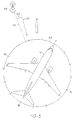
- Figures 3-5 illustrate the method shown in Figure 2 in greater detail.
- the aircraft is first directed, or oriented, in a first heading.
- the actual bearing 12 from the aircraft 10 to an ADF station 14 is determined.
- the actual bearing 12 is determined using the on-board GPS system 32 and the navigation database 34, shown in Figure 1.
- the GPS system 32 is used to determine the location (i.e., latitude and longitude) of the aircraft 10, and the navigation database 34 is used to determine the location of the ADF station 58.
- modern GPS systems and navigation databases are extremely accurate. Therefore, the system 12 will be able to accurately determine the bearing between the aircraft 10 and the ADF station 58. Therefore, as illustrated in Figures 3-5, the actual bearing 56 accurately depicts the bearing from the aircraft 10 to the ADF station 58.
- the ADF bearing 60 is then determined by receiving an ADF signal transmitted by the ADF station 58 using the ADF system 36, as is commonly understood.
- the actual bearing 56 and the ADF bearing 60 to the ADF station 58 may differ due to various types of error, such as quadrantal error.
- An angle 62 between the actual bearing 56 and the ADF bearing 60 may represent the ADF error for the particular heading shown in Figure 3.
- both the actual bearing 56 and the ADF bearing 60 lie within the fourth quadrant of a compass rose 64 that indicates the heading of the aircraft 10, and the ADF bearing 60 is slightly more northern than (i.e., lies clockwise from) the actual bearing 56.
- Figure 4 illustrates the aircraft 10 oriented in a second heading while being turned and a second reading is being taken.
- the aircraft 10 has been rotated but has not changed locations.
- the ADF station 58 is located in the same direction relative to the aircraft.
- the aircraft 10 has been rotated such that the actual bearing 56 to the ADF station 58 and the ADF bearing lie within the second quadrant of the compass rose 64.
- the ADF bearing 60 has moved relative to the actual bearing 56 and is now counterclockwise of the actual bearing 56. Therefore, the ADF error 62 for the second heading is different than that of the first heading.
- Figure 5 illustrates the aircraft oriented in a third heading while a third reading is being taken. Again the ADF bearing 60 has changed relative to the actual bearing 56, and as a result, the third heading as an ADF error 62 that is different than that for the first and second headings.
- the process shown in Figures 3 - 5 may be performed while the aircraft is on the ground.
- the system 12 shown in Figure 1 is set to an "ADF error correction mode" or "ADF calibration mode”
- a user may manually rotate or turn the aircraft in a complete circle.
- the system 12 is capable of automatically calculating the starting point and detecting when the aircraft 12 has been turned 360 degrees.
- the process may be repeated numerous times.
- the system 12 of Figure 1 may include a minimum number of readings that must be taken in order for the calibration function to be generated. Once the calibration function is generated, during operation of the aircraft 10, the system 12 uses the calibration function to compensate the ADF reading for the ADF error described above so that an accurate ADF bearing is provided to the user, or pilot, of the aircraft.
- One advantage of the method and system described above is that there is no need to be able to physically access the ADF antenna. Therefore, the amount of physical labor involved is greatly reduced. Another advantage is that the calibration process may be performed by turning the aircraft only once. As a result, the amount of labor is even further reduced, as is the time required to perform the calibration process. A further advantage is that the accuracy of the calibration process is increased.
Landscapes
- Physics & Mathematics (AREA)
- Engineering & Computer Science (AREA)
- General Physics & Mathematics (AREA)
- Radar, Positioning & Navigation (AREA)
- Remote Sensing (AREA)
- Position Fixing By Use Of Radio Waves (AREA)
Abstract
Description
- The present invention generally relates to an aviation system, and more particularly relates to a method and system for calibrating aviation equipment.
- One common method used in the navigation of aircraft is known as radio direction finding, in which the direction from the aircraft to a known radio source is determined using an antenna. Presently, many aircraft include automatic direction finders (ADFs) which automatically detect the direction to a particular ADF station using a directional antenna. However, the readings given by ADFs may not be accurate, and as a result, the ADF systems in modern aircraft may need to be regularly calibrated.
- Current methods for calibrating an ADF system in an aircraft can be labor intensive and time consuming, and thus, expensive. The most common method for calibrating an ADF system involves initially pointing the aircraft directly at the known location of an ADF station, rotating the aircraft to various bearings, such as every 45 degrees, and noting the error at each bearing. The ADF error, such as quadrantal error, may then be corrected by tuning a potentiometer in the antenna.
- However, the antenna is often not easily accessible, and can only be reached by crawling through small access channels within the aircraft. Also, after each adjustment, the entire process must be repeated until the quadrantal error is reduced to an acceptable level. Furthermore, other types of error, besides quadrantal error, can not be corrected.
- Accordingly, it is desirable to provide a method and system for calibrating on-board aviation equipment, such as an ADF system, that reduces the amount of labor involved. In addition, it is desirable to provide a method and system for calibrating on-board aviation equipment that corrects for all types of error. Furthermore, other desirable features and characteristics of the present invention will become apparent from the subsequent detailed description and the appended claims, taken in conjunction with the accompanying drawings and the foregoing technical field and background.
- A method is provided for calibrating on-board aviation equipment. The method comprises determining an actual bearing from an aircraft to an automatic direction finder (ADF) station, moving the aircraft to a plurality of headings, determining an ADF bearing from the aircraft to the ADF station at each of the plurality of headings to which the aircraft is moved, calculating an error between the actual bearing and each of the determined ADF bearings, and generating an error function based at least in part on the calculated errors.
- A system is provided for calibrating on-board aviation equipment. The system comprises an aircraft and a computing system on-board the aircraft. The computing system is configured to calculate error between an actual bearing from the aircraft to an ADF station and a plurality of ADF bearings from the aircraft to the ADF station, each ADF bearing being associated with a respective one of a plurality of headings of the aircraft, and generate an ADF error function based at least in part on the calculated error..
In the Drawings; - The present invention will hereinafter be described in conjunction with the following drawing figures, wherein like numerals denote like elements, and
- Figure 1 is block diagram schematically illustrating an aircraft and an avionics system on-board the aircraft;
- Figure 2 is a flow chart illustrating a method for calibrating on-board aviation equipment according to one embodiment of the present invention; and
- Figures 3 - 5 are top plan schematic views of a system for calibrating on-board aviation equipment utilizing the method illustrated in Figure 2.
- The following detailed description of the invention is merely exemplary in nature and is not intended to limit the invention or the application and uses of the invention. Furthermore, there is no intention to be bound by any theory presented in the preceding background of the invention or the following detailed description of the invention. It should also be understood that Figures 1 - 5 are merely illustrative and may not be drawn to scale.
- Figure 1 to Figure 5 illustrate a method and system for calibrating on-board aviation equipment. An aircraft is positioned, or oriented, in a first heading or bearing. An actual bearing from the aircraft to an automatic direction finder (ADF) station is then determined. The actual bearing is relative to the nose of the aircraft and may be determined using the heading of the aircraft and a known bearing from the aircraft to the ADF station. In one embodiment, the actual bearing is determined using a Global Positioning Satellite (GPS) system and a navigational database, which includes the latitude and longitude of the ADF station. An "ADF bearing" is then determined using an ADF system on the aircraft by receiving radio signals that are transmitted by the ADF station. The ADF error for the particular heading is then calculated. The ADF error may be the difference between the actual bearing and the ADF bearing. The above information is stored on a memory located within the avionics system on-board the aircraft. The aircraft is then rotated to a second heading, the process is repeated for the second bearing, and the information is again stored onto the memory. The process may be repeated numerous times, as the aircraft is rotated in a complete circle, and after a predetermined number of readings are taken, the avionics system may create a calibration, or error, function as a function of the heading of the aircraft. During operation the avionics system may apply the calibration function to the bearing indicated by the ADF system.
- FIG. 1 schematically illustrates an
aircraft 10 with an on-board navigation and control/avionics system 12, according to one embodiment of the present invention. Theaircraft 10 may be any one of a number of different types of aircraft such as, for example, a private propeller or jet engine driven airplane, a commercial jet liner, or a helicopter. Thesystem 12 includes a flight management system (FMS) 14, a control display unit (CDU) 16, an autopilot orautomated guidance system 18, multiple flight control surfaces 20 (e.g., ailerons, elevators, and a rudder), an Air Data Computer (ADC) 22, analtimeter 24, an Air Data System (ADS) 26, andmultiple sensors 28. Thesystem 12 also includes adata bus 30, which operably couples the other components of thesystem 12. Although not illustrated, thesensors 28 may include a barometric pressure sensor, a thermometer, and a wind speed sensor, and theADS 26 may include a pitostatic tube system, as is commonly understood in the art. - As illustrated, the
system 12 also includes a Global Positioning System (GPS) (or Global Positioning Satellite system), anavigation database 34, an ADF system 36 (including an ADF receiver), acompass 38, and aprocessor 40, all of which are operably coupled through thedata bus 30. Theprocessor 40 further includes a microprocessor and a memory. It should also be understood that although theprocessor 40 is shown as a separate component of thesystem 12, theprocessor 40 may be integrated into one of the other components of thesystem 12, such as theGPS system 32 orADF system 36. - Figure 2 illustrates a method for calibrating the on-board aviation equipment, in particular the
ADF system 36, shown in Figure 1. In this regard, the method may be described in terms of functional block components and various processing steps. However, it should be understood that such functional blocks may be realized by any number of hardware, firmware, and/or instructions stored on a computer readable medium (i.e., software) to be carried out by a computing system (i.e., thesystem 12 shown in Figure 1) and may be implemented in whole or in part using electronic components, including various circuitry and integrated circuits, such as an Application Specific Integration Circuit (ASIC), or with instructions stored on a computer readable medium to be carried out by a computing system. - Still referring to Figure 2, at
step 42, the calibration is begun by setting the system to an ADF calibration, or alignment, mode. Atstep 44, the aircraft is positioned in a first heading. As will be appreciated by one skilled in the art, the heading of the aircraft may be determined by utilizing the compass on-board the aircraft. Then, atstep 46, an actual bearing from the aircraft to an ADF station is determined. Atstep 48, an "ADF bearing" (i.e., as indicated by the on-board ADF system) from the aircraft to the ADF station is determined. Next, atstep 50, an ADF error for the particular heading in which the aircraft is positioned is calculated. The ADF error may simply be the difference between the actual bearing and the ADF bearing. Although not specifically illustrated, the current heading and the ADF error associated with the current heading may then be stored in the memory of theprocessor 40 shown in Figure 1. Atstep 52, the determination is made as to whether or not a sufficient (i.e., a pre-set minimum) number of readings have been taken for the calibration. If the minimum number of readings have not been taken and stored, the process returns to step 2, at which point the aircraft is positioned in a different heading. The method then continues and repeats as described above for each heading. If the minimum number of readings has been taken, atstep 54, a calibration (or error) function or algorithm is generated. As will be appreciated by one skilled in the art, the calibration function may be a function of the heading of the aircraft. - Figures 3-5 illustrate the method shown in Figure 2 in greater detail. As shown in Figure 3, the aircraft is first directed, or oriented, in a first heading. As described above, the actual bearing 12 from the
aircraft 10 to an ADFstation 14 is determined. In one embodiment, theactual bearing 12 is determined using the on-board GPS system 32 and thenavigation database 34, shown in Figure 1. TheGPS system 32 is used to determine the location (i.e., latitude and longitude) of theaircraft 10, and thenavigation database 34 is used to determine the location of theADF station 58. As will be appreciated by one skilled in the art, modern GPS systems and navigation databases are extremely accurate. Therefore, thesystem 12 will be able to accurately determine the bearing between theaircraft 10 and theADF station 58. Therefore, as illustrated in Figures 3-5, theactual bearing 56 accurately depicts the bearing from theaircraft 10 to theADF station 58. - Still referring to Figure 3, the ADF bearing 60 is then determined by receiving an ADF signal transmitted by the
ADF station 58 using theADF system 36, as is commonly understood. As shown, theactual bearing 56 and the ADF bearing 60 to theADF station 58 may differ due to various types of error, such as quadrantal error. Anangle 62 between theactual bearing 56 and the ADF bearing 60 may represent the ADF error for the particular heading shown in Figure 3. As shown, both theactual bearing 56 and the ADF bearing 60 lie within the fourth quadrant of acompass rose 64 that indicates the heading of theaircraft 10, and the ADF bearing 60 is slightly more northern than (i.e., lies clockwise from) theactual bearing 56. - Figure 4 illustrates the
aircraft 10 oriented in a second heading while being turned and a second reading is being taken. It should be noted that in the example illustrated in Figures 3 - 5, theaircraft 10 has been rotated but has not changed locations. Thus, theADF station 58 is located in the same direction relative to the aircraft. Theaircraft 10 has been rotated such that theactual bearing 56 to theADF station 58 and the ADF bearing lie within the second quadrant of the compass rose 64. As illustrated, the ADF bearing 60 has moved relative to theactual bearing 56 and is now counterclockwise of theactual bearing 56. Therefore, theADF error 62 for the second heading is different than that of the first heading. - Figure 5 illustrates the aircraft oriented in a third heading while a third reading is being taken. Again the ADF bearing 60 has changed relative to the
actual bearing 56, and as a result, the third heading as anADF error 62 that is different than that for the first and second headings. - The process shown in Figures 3 - 5 may be performed while the aircraft is on the ground. After the
system 12 shown in Figure 1 is set to an "ADF error correction mode" or "ADF calibration mode," a user may manually rotate or turn the aircraft in a complete circle. Using theGPS system 32 along with thecompass 38, thesystem 12 is capable of automatically calculating the starting point and detecting when theaircraft 12 has been turned 360 degrees. - As described above, the process may be repeated numerous times. The
system 12 of Figure 1 may include a minimum number of readings that must be taken in order for the calibration function to be generated. Once the calibration function is generated, during operation of theaircraft 10, thesystem 12 uses the calibration function to compensate the ADF reading for the ADF error described above so that an accurate ADF bearing is provided to the user, or pilot, of the aircraft. - Other embodiments may not require all of the components illustrated in Figures 1 and 2. The process described above can performed without a GPS system with a known starting heading. For example, some airfields have markers on the ground which precisely indicate particular bearings, such as direction (e.g., north) or towards a particular ADF station. The known bearing can be used in place of the
actual bearing 56 illustrated in Figures 3 - 5, as will be appreciated by one skilled in the an. The process may also be performed using the GPS system while the aircraft is in flight by simply flying the aircraft in a slow, controlled complete turn during the calibration process. - One advantage of the method and system described above is that there is no need to be able to physically access the ADF antenna. Therefore, the amount of physical labor involved is greatly reduced. Another advantage is that the calibration process may be performed by turning the aircraft only once. As a result, the amount of labor is even further reduced, as is the time required to perform the calibration process. A further advantage is that the accuracy of the calibration process is increased.
- While at least one exemplary embodiment has been presented in the foregoing detailed description of the invention, it should be appreciated that a vast number of variations exist. It should also be appreciated that the exemplary embodiment or exemplary embodiments are only examples, and are not intended to limit the scope, applicability, or configuration of the invention in any way. Rather, the foregoing detailed description' will provide those skilled in the art with a convenient road map for implementing an exemplary embodiment of the invention. It being understood that various changes may be made in the function and arrangement of elements described in an exemplary embodiment without departing from the scope of the invention as set forth in the appended claims.
Claims (10)
- A method comprising:determining an actual bearing (56) from an aircraft (10) to an automatic direction finder (ADF) station (58);moving the aircraft (10) to a plurality of headings;determining an ADF bearing (60) from the aircraft (10) to the ADF station (58) at each of the plurality of headings to which the aircraft (10) is moved;calculating an error (62) between the actual bearing (56) and each of the determined ADF bearings (60); andgenerating an error function based at least in part on the calculated errors (62).
- The method of claim 1, wherein the actual bearing (56) is obtained using a Global Positioning Satellite (GPS) system (32) and a navigational database (34) including latitude and longitude coordinates for the ADF station (58).
- The method of claim 2, wherein at least two of the headings are in different quadrants of a compass (64).
- The method of claim 3, wherein the ADF bearing (60) for each respective heading is obtained with an ADF receiver (36) on-board the aircraft (10) that receives a signal transmitted from the ADF station (58).
- The method of claim 4, wherein said calculating the error (62) between the actual bearing (56) and the ADF bearing (60) for each respective heading of the aircraft (10) and said generating the error function are performed by a computing system (12) on-board the aircraft (10).
- The method of claim 5, further comprising determining the actual bearing (56) for each respective heading of the aircraft (10).
- The method of claim 6, wherein said determining of the actual bearing (56) and said determining of the ADF bearing (60) for each respective heading of the aircraft (10) are performed while the aircraft (10) is in flight.
- A system for calibrating on-board aviation equipment comprising:an aircraft (10); anda computing system (12) on-board the aircraft (10) configured to:calculate error (62) between an actual bearing (56) from the aircraft (10) to an automatic direction finder (ADF) station (58) and a plurality of ADF bearings (60) from the aircraft (10) to the ADF station (58), each ADF bearing (60) being associated with a respective one of a plurality of headings of the aircraft (10); andgenerate an ADF error function based at least in part on the calculated error (62).
- The system of claim 8, further comprising an ADF receiver (36) on-board the aircraft (10) and in operable communication with the computing system (12) to receive a signal transmitted by the ADF station (58) and a Global Positioning Satellite (GPS) system (32) on-board the aircraft (10) and in operable communication with the computing system (12) and the ADF receiver (36).
- The system of claim 9, further comprising a navigation database (34) on-board the aircraft (10) and in operable communication with the computing system (12), the ADF receiver (36), and the GPS system (32), the navigation database (34) including latitude and longitude coordinates for the ADF station (58) and wherein the computing system (12) is further configured to determine the actual bearing (60) using the GPS system (32) and the navigation database (34).
Applications Claiming Priority (1)
| Application Number | Priority Date | Filing Date | Title |
|---|---|---|---|
| US11/351,628 US7499803B2 (en) | 2006-02-10 | 2006-02-10 | System and method for calibrating on-board aviation equipment |
Publications (1)
| Publication Number | Publication Date |
|---|---|
| EP1818681A1 true EP1818681A1 (en) | 2007-08-15 |
Family
ID=37964991
Family Applications (1)
| Application Number | Title | Priority Date | Filing Date |
|---|---|---|---|
| EP07102148A Withdrawn EP1818681A1 (en) | 2006-02-10 | 2007-02-12 | A system and method for calibrating on-board aviation equipment |
Country Status (2)
| Country | Link |
|---|---|
| US (1) | US7499803B2 (en) |
| EP (1) | EP1818681A1 (en) |
Cited By (4)
| Publication number | Priority date | Publication date | Assignee | Title |
|---|---|---|---|---|
| RU2451948C1 (en) * | 2011-01-12 | 2012-05-27 | Федеральное государственное унитарное предприятие "18 Центральный научно-исследовательский институт" Министерства обороны Российской Федерации | Method of calibrating mobile shortwave direction finder with multielement antenna array |
| RU2454677C1 (en) * | 2010-10-19 | 2012-06-27 | Открытое акционерное общество "Конструкторское бюро приборостроения" | Method of determining systematic errors in locating missile and target using monopulse system |
| RU2640354C1 (en) * | 2016-11-14 | 2017-12-28 | Федеральное государственное унитарное предприятие "Ростовский-на-Дону научно-исследовательский институт радиосвязи" (ФГУП "РНИИРС") | Method of complex calibration of position finder- correlation interferometer on mobile carrier |
| EP4119971A1 (en) * | 2021-07-13 | 2023-01-18 | Bull SAS | Method for calibrating an airborne goniometry for low frequencies |
Families Citing this family (8)
| Publication number | Priority date | Publication date | Assignee | Title |
|---|---|---|---|---|
| US8331888B2 (en) * | 2006-05-31 | 2012-12-11 | The Boeing Company | Remote programmable reference |
| US7558688B2 (en) * | 2007-04-20 | 2009-07-07 | Northrop Grumman Corporation | Angle calibration of long baseline antennas |
| EP2219587A4 (en) * | 2007-11-14 | 2012-11-21 | Univ California | Sterol-modified amphiphilic lipids |
| US8264408B2 (en) | 2007-11-20 | 2012-09-11 | Nokia Corporation | User-executable antenna array calibration |
| US9024812B2 (en) * | 2010-04-28 | 2015-05-05 | Aviation Communication & Surveillance Systems Llc | Systems and methods for providing antenna calibration |
| US20120299763A1 (en) * | 2011-05-27 | 2012-11-29 | Avidyne Corporation | Position determining method and system using surveillance ground stations |
| EP2533123B1 (en) * | 2011-06-09 | 2016-12-28 | AIRBUS HELICOPTERS DEUTSCHLAND GmbH | Navigation system for an aircraft and method of operating such a navigation system |
| WO2015054835A1 (en) * | 2013-10-16 | 2015-04-23 | Nokia Technologies Oy | Methods, apparatuses and computer program products for calibration of antenna array |
Citations (4)
| Publication number | Priority date | Publication date | Assignee | Title |
|---|---|---|---|---|
| US5526001A (en) * | 1992-12-11 | 1996-06-11 | Litton Systems Inc. | Precise bearings only geolocation in systems with large measurements bias errors |
| WO2000002009A1 (en) * | 1998-07-06 | 2000-01-13 | Alliedsignal Inc. | Aircraft position validation using radar and digital terrain elevation database |
| US6208937B1 (en) * | 1998-07-29 | 2001-03-27 | Litton Systems Inc. | Method and apparatus for generating navigation data |
| US6784840B2 (en) * | 2002-12-23 | 2004-08-31 | Itt Manufacturing Enterprises, Inc. | Method for determining azimuth and elevation angles using a single axis direction finding system |
Family Cites Families (2)
| Publication number | Priority date | Publication date | Assignee | Title |
|---|---|---|---|---|
| US6542796B1 (en) * | 2000-11-18 | 2003-04-01 | Honeywell International Inc. | Methods and apparatus for integrating, organizing, and accessing flight planning and other data on multifunction cockpit displays |
| US7054739B2 (en) * | 2003-05-01 | 2006-05-30 | Honeywell International Inc. | Radio navigation system |
-
2006
- 2006-02-10 US US11/351,628 patent/US7499803B2/en not_active Expired - Fee Related
-
2007
- 2007-02-12 EP EP07102148A patent/EP1818681A1/en not_active Withdrawn
Patent Citations (4)
| Publication number | Priority date | Publication date | Assignee | Title |
|---|---|---|---|---|
| US5526001A (en) * | 1992-12-11 | 1996-06-11 | Litton Systems Inc. | Precise bearings only geolocation in systems with large measurements bias errors |
| WO2000002009A1 (en) * | 1998-07-06 | 2000-01-13 | Alliedsignal Inc. | Aircraft position validation using radar and digital terrain elevation database |
| US6208937B1 (en) * | 1998-07-29 | 2001-03-27 | Litton Systems Inc. | Method and apparatus for generating navigation data |
| US6784840B2 (en) * | 2002-12-23 | 2004-08-31 | Itt Manufacturing Enterprises, Inc. | Method for determining azimuth and elevation angles using a single axis direction finding system |
Cited By (5)
| Publication number | Priority date | Publication date | Assignee | Title |
|---|---|---|---|---|
| RU2454677C1 (en) * | 2010-10-19 | 2012-06-27 | Открытое акционерное общество "Конструкторское бюро приборостроения" | Method of determining systematic errors in locating missile and target using monopulse system |
| RU2451948C1 (en) * | 2011-01-12 | 2012-05-27 | Федеральное государственное унитарное предприятие "18 Центральный научно-исследовательский институт" Министерства обороны Российской Федерации | Method of calibrating mobile shortwave direction finder with multielement antenna array |
| RU2640354C1 (en) * | 2016-11-14 | 2017-12-28 | Федеральное государственное унитарное предприятие "Ростовский-на-Дону научно-исследовательский институт радиосвязи" (ФГУП "РНИИРС") | Method of complex calibration of position finder- correlation interferometer on mobile carrier |
| EP4119971A1 (en) * | 2021-07-13 | 2023-01-18 | Bull SAS | Method for calibrating an airborne goniometry for low frequencies |
| US11994602B2 (en) | 2021-07-13 | 2024-05-28 | Bull Sas | Method for calibrating an airborne goniometry apparatus for low frequencies |
Also Published As
| Publication number | Publication date |
|---|---|
| US7499803B2 (en) | 2009-03-03 |
| US20070191999A1 (en) | 2007-08-16 |
Similar Documents
| Publication | Publication Date | Title |
|---|---|---|
| US7499803B2 (en) | System and method for calibrating on-board aviation equipment | |
| US6512976B1 (en) | Method and system for terrain aided navigation | |
| EP3073225B1 (en) | Aircraft synthetic vision systems utilizing data from local area augmentation systems, and methods for operating such aircraft synthetic vision systems | |
| US5394333A (en) | Correcting GPS position in a hybrid naviation system | |
| US5969676A (en) | Radio frequency interferometer and laser rangefinder/destination base targeting system | |
| EP1860456B1 (en) | Methods and systems for radar aided aircraft positioning for approaches and landings | |
| US8909471B1 (en) | Voting system and method using doppler aided navigation | |
| US8868265B2 (en) | System and method for aligning aircraft and runway headings during takeoff roll | |
| US8498758B1 (en) | ILS-based altitude data generation system, device, and method | |
| EP1393093A2 (en) | Method of and system for calibrating and ig/gp navigational system | |
| WO2008097346A4 (en) | Method for fusing multiple gps measurement types into a weighted least squares solution | |
| GB2444814A (en) | Estimating inertial acceleration bias errors | |
| US20040267444A1 (en) | Hybrid intertial navigation unit with improved altitude integrity | |
| US20020188386A1 (en) | GPS based terrain referenced navigation system | |
| US9453921B1 (en) | Delayed-based geographic position data generation system, device, and method | |
| US6845304B1 (en) | Method of and system for deriving inertial-aided deviations for autoland systems during GPS signal interruptions | |
| US20040220722A1 (en) | Radio navigation system | |
| US8321074B1 (en) | Altitude data generation system, device, and method | |
| CN105466423A (en) | Unmanned aerial vehicle navigation system and operation method thereof | |
| US11789927B2 (en) | Method for validating at least one predetermined position data stored in an aircraft database, associated computer program and device | |
| US20240253829A1 (en) | Radio ranging for gps-denied landing of unmanned aircraft | |
| KR20180128173A (en) | A method for calculating a Real-Time Heading value of object using EKF-Cl | |
| KR102093888B1 (en) | Assistance navigation equipment and control method thereof | |
| US11054262B2 (en) | Method for reducing in-transit navigational errors | |
| EP1478939A2 (en) | Aircraft gps instrumentation system and related method |
Legal Events
| Date | Code | Title | Description |
|---|---|---|---|
| PUAI | Public reference made under article 153(3) epc to a published international application that has entered the european phase |
Free format text: ORIGINAL CODE: 0009012 |
|
| AK | Designated contracting states |
Kind code of ref document: A1 Designated state(s): AT BE BG CH CY CZ DE DK EE ES FI FR GB GR HU IE IS IT LI LT LU LV MC NL PL PT RO SE SI SK TR |
|
| AX | Request for extension of the european patent |
Extension state: AL BA HR MK YU |
|
| 17P | Request for examination filed |
Effective date: 20080205 |
|
| 17Q | First examination report despatched |
Effective date: 20080305 |
|
| AKX | Designation fees paid |
Designated state(s): CH DE FR GB LI |
|
| GRAP | Despatch of communication of intention to grant a patent |
Free format text: ORIGINAL CODE: EPIDOSNIGR1 |
|
| RAP1 | Party data changed (applicant data changed or rights of an application transferred) |
Owner name: HONEYWELL INTERNATIONAL INC. |
|
| STAA | Information on the status of an ep patent application or granted ep patent |
Free format text: STATUS: THE APPLICATION IS DEEMED TO BE WITHDRAWN |
|
| 18D | Application deemed to be withdrawn |
Effective date: 20090620 |